

Application Note AN-1035 - International Rectifier
Application Note AN-1035 - International Rectifier
Application Note AN-1035 - International Rectifier

Create successful ePaper yourself
Turn your PDF publications into a flip-book with our unique Google optimized e-Paper software.
7. Heat the site to approximately 100°C (150°C for<br />
lead-free assembly) using the substrate heating<br />
stage.<br />
8. Use the de-soldering tool to heat both device and<br />
solder interconnects to reflow temperature,<br />
waiting until all the solder has reflowed.<br />
9. Retract the arm, leaving the device in place. Cool<br />
as quickly as possible.<br />
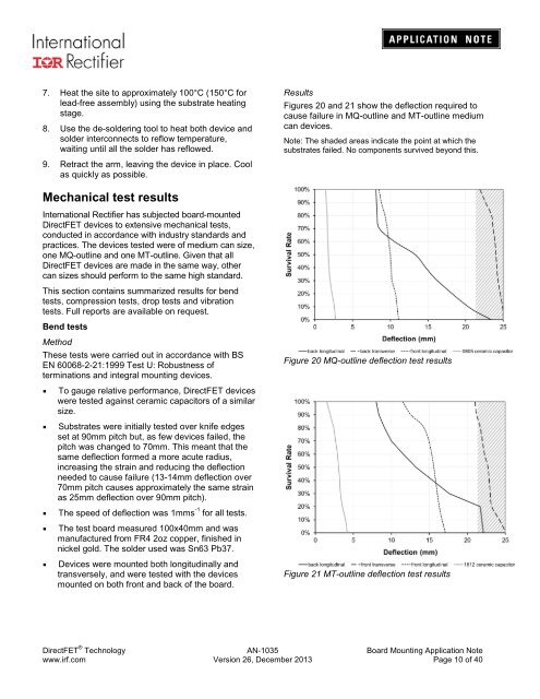
Results<br />
Figures 20 and 21 show the deflection required to<br />
cause failure in MQ-outline and MT-outline medium<br />
can devices.<br />
<strong>Note</strong>: The shaded areas indicate the point at which the<br />
substrates failed. No components survived beyond this.<br />
Mechanical test results<br />
<strong>International</strong> <strong>Rectifier</strong> has subjected board-mounted<br />
DirectFET devices to extensive mechanical tests,<br />
conducted in accordance with industry standards and<br />
practices. The devices tested were of medium can size,<br />
one MQ-outline and one MT-outline. Given that all<br />
DirectFET devices are made in the same way, other<br />
can sizes should perform to the same high standard.<br />
This section contains summarized results for bend<br />
tests, compression tests, drop tests and vibration<br />
tests. Full reports are available on request.<br />
Bend tests<br />
Method<br />
These tests were carried out in accordance with BS<br />
EN 60068-2-21:1999 Test U: Robustness of<br />
terminations and integral mounting devices.<br />
Figure 20 MQ-outline deflection test results<br />
• To gauge relative performance, DirectFET devices<br />
were tested against ceramic capacitors of a similar<br />
size.<br />
• Substrates were initially tested over knife edges<br />
set at 90mm pitch but, as few devices failed, the<br />
pitch was changed to 70mm. This meant that the<br />
same deflection formed a more acute radius,<br />
increasing the strain and reducing the deflection<br />
needed to cause failure (13-14mm deflection over<br />
70mm pitch causes approximately the same strain<br />
as 25mm deflection over 90mm pitch).<br />
• The speed of deflection was 1mms -1 for all tests.<br />
• The test board measured 100x40mm and was<br />
manufactured from FR4 2oz copper, finished in<br />
nickel gold. The solder used was Sn63 Pb37.<br />
• Devices were mounted both longitudinally and<br />
transversely, and were tested with the devices<br />
mounted on both front and back of the board.<br />
Figure 21 MT-outline deflection test results<br />
DirectFET ® Technology <strong>AN</strong>-<strong>1035</strong> Board Mounting <strong>Application</strong> <strong>Note</strong><br />
www.irf.com Version 26, December 2013 Page 10 of 40


