

Application Note AN-1150 - International Rectifier
Application Note AN-1150 - International Rectifier
Application Note AN-1150 - International Rectifier

Create successful ePaper yourself
Turn your PDF publications into a flip-book with our unique Google optimized e-Paper software.
as mentioned earlier, for the PFC converter, the most important criterion for<br />
basing the selection of the compensation component values is the voltage loop<br />
bandwidth.<br />
Fig10: Voltage Loop error amplifier compensation network<br />
The error amplifier transfer function is given by:<br />
gm<br />
⋅(<br />
1+<br />
sRgmCZ<br />
)<br />
H<br />
2<br />
( s ) =<br />
s( C + C + sR C C<br />
Z<br />
where g m is the transconductance of the voltage error amplifier. The<br />
compensation network adds a zero and a pole in the transfer function at:<br />
f<br />
f<br />
P0<br />
Z 0<br />
= π ⋅<br />
P<br />
1<br />
2 R<br />
=<br />
2π ⋅ R<br />
gm<br />
⋅ C<br />
gm<br />
Z<br />
1<br />
Cz ⋅Cp<br />
Cz + Cp<br />
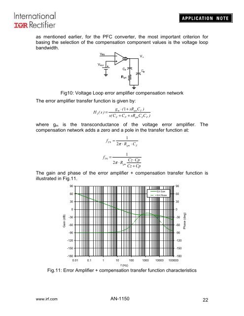
The gain and phase of the error amplifier + compensation transfer function is<br />
illustrated in Fig.11.<br />
gm<br />
Z<br />
P<br />
)<br />
90<br />
60<br />
30<br />
0<br />
EA Gain<br />
EA Phase<br />
90<br />
60<br />
30<br />
0<br />
Gain (dB)<br />
-30<br />
-60<br />
-90<br />
-120<br />
-150<br />
-30<br />
-60<br />
-90<br />
-120<br />
-150<br />
Phase (deg)<br />
-180<br />
-180<br />
0.01 0.1 1 10 100 1000 10000 100000<br />
f (Hz)<br />
Fig.11: Error Amplifier + compensation transfer function characteristics<br />
www.irf.com <strong>AN</strong>-<strong>1150</strong><br />
22


