Darren Barge Presentation - IQPC.com
Darren Barge Presentation - IQPC.com
Darren Barge Presentation - IQPC.com

Create successful ePaper yourself
Turn your PDF publications into a flip-book with our unique Google optimized e-Paper software.
Wel<strong>com</strong>e from BMA
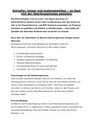
BMA Ownership Structure<br />
Mitsubishi<br />
50%<br />
BMA Owners<br />
50%<br />
Council<br />
Illawarra Coal<br />
Operations<br />
Peak Downs Mine Saraji Mine Goonyella Riverside Mine<br />
Norwich Park Mine Blackwater Mine Gregory<br />
Mine<br />
Broadmeadow Mine<br />
Hay Point Terminal Crinum Mine<br />
Marketing<br />
Singapore<br />
Brisbane<br />
The Hague<br />
Other regional offices<br />
BHP Billiton<br />
Mitsui & Co<br />
80% 20%<br />
BHP Mitsui Coal P/L<br />
Poitrel Mine<br />
South Walker Creek Mine
Safety is priority number 1<br />
Our Goal is zero harm<br />
We are successful when each employee ends each day safely<br />
The safety of our employees and contractors is an integral<br />
part of our business<br />
Environment<br />
Minimising the environmental impact of our operations<br />
remains a priority into the future.<br />
Community<br />
BMA is a proud contributor to the <strong>com</strong>munity
Norwich Park processing operation
Structure replacement project<br />
The crushed Raw coal conveyor structure is critical as the<br />
only means of stockpiling raw coal for plant feed.<br />
The plant has a 1560 TPH name plate feed capacity with a<br />
current 73% yield for coke product<br />
In July 2006 ,I was faced by a report of a high potential major<br />
structure risk.<br />
The project was vital to the business success at Norwich Park<br />
as well as the flow on effect to BMA.<br />
Charter : to design and install a replacement structure to<br />
enable safe and efficient operation and delivery of crushed<br />
raw coal to the plant feed stockpile.<br />
Incorporate leading practise designs to ensure the operations<br />
and maintenance stakeholders for the project benefited from<br />
the replacement.
Key stakeholders<br />
Main structure design by Maintenance Technology Institute<br />
,MTI by Dr Daya Dayawansa and Dr Brian Kerezsi.<br />
Principle Contractor Fabrication and Installation<br />
by McBryde Corporation.<br />
Project management assistance<br />
by RKF Engineering ,Paul Hallett<br />
Independent design review for main structure<br />
by ASPEC Engineering. Craig Meng<br />
Electrical Engineering Design<br />
by Welcon Technologies ,George Baker.<br />
Electrical installation<br />
by O'Donnell Griffin
Background details<br />
Original design based on I beam main chords and extensive<br />
use of back to back angles with spacers and a flexible<br />
sealed joint approximately 10 mm wide
Maintenance & operation history<br />
Due to the limited access to a large number of the<br />
cross bracing a visual inspection from a distance<br />
had been the process utilised for structural integrity<br />
reporting and replacement planning.<br />
Bracing replacement had been ongoing for two<br />
years previous.<br />
A dramatic change had been seen with a number of<br />
critical members showing signs of deformation<br />
between the angles.
Gathering thickness data<br />
A program of thickness testing the entire structure during<br />
scheduled maintenance periods was initiated and allowed a<br />
team to access via the use of crane and dog box to ultra<br />
sonic test all members in three position along the length of<br />
structural members. Red denotes >50% loss.
Design modelling & failure mode<br />
With the assistance of MTI a full design model was created to<br />
reflect the actual stability and strength and potential failure<br />
mode
Risk management during operation<br />
Due to the time frame of a structure replacement a<br />
operational risk management strategy had to be<br />
initiated to ensure no people were put at risk.<br />
A wind speed monitoring system was incorporated<br />
to raise a full screen alarm page informing the<br />
control room operator of actions required, retract<br />
all machinery from stockpile area, raise telescopic<br />
chute to maximum raised position stop feed to<br />
ROM.<br />
Personnel were not allowed on the running system<br />
at this stage of the project
Replacement design & objectives<br />
The replacement of the main structure created a<br />
fantastic opportunity to build a structure that would<br />
not only be a replacement but allow the inclusion of<br />
current best practise design and standards.<br />
The structure utilised Square hollow sections as the<br />
main chords and vertical bracing.<br />
The Horizontal bracing was all round section to<br />
minimise any potential coal build up.<br />
All members were fully welded.
Benefits from the design<br />
Incorporation of access stair way to allow close<br />
inspection of all main chord nodes.<br />
Reduce flat surface areas for any build up potential.<br />
Pressure test points for the main chords for<br />
conformation of seal integrity.<br />
Inclusion of a maintenance level platform for the<br />
telescopic chute probes sheaves and dust<br />
suppression.<br />
Top of belt covers to encapsulate and run back and<br />
possible spillage.
Fabrication & Transport<br />
All structure was fabricated off site and transported<br />
in three major sections.<br />
The transport to site was a challenge on its own but<br />
with the use of house removal transport technology<br />
we were able to minimise the amount of bridge and<br />
electrical interference so the permits required were<br />
greatly reduced.<br />
S1 and S2 spans were pre piped and transported<br />
ready to install.
On site assembly<br />
The assembly took place on a pad area on the raw<br />
coal stock pile where we had pre poured a series of<br />
concrete piers with beams and levelling studs.<br />
Once fully aligned the final welding was <strong>com</strong>pleted.<br />
All walkway sections were fitted out with cable<br />
ladder and pre wired.<br />
Conveyor gantry sections were fitted out with<br />
frames and rollers ready for lifting into final<br />
position.
New structure ready for install<br />
Structure on levelling beams.
Demolition<br />
A large number of scenarios were calculated for the lifting<br />
plan to lower the old structure.<br />
The large uncertainty was how the structure would react once<br />
taken from <strong>com</strong>pression into a tension state<br />
The final plan chosen was to cut the structure and lower in two<br />
pieces.
Demolition Photos<br />
S4 Span lowered ,Day 3.
Demolition Photos<br />
S3 span lowered Day 4,preparing main column studs.
Installation & alignment<br />
The main column frame was pre installed and the new structure<br />
lowered into position for in situ welding of the S3 & S4 spans.<br />
Alignment was set from the rear pin positions and survey<br />
points.
Main structure lift and positioning<br />
Main S3 & S4 positioning. day 7.
Installation of pre assembled galleries<br />
Fitted with frames , rollers & cable ladders.
The work in progress<br />
Head end platform and south walkway
Beltreco covers<br />
The covers have eliminated spillage from run back.
Dry <strong>com</strong>missioning <strong>com</strong>pleted ,Day 19
First Coal Day 20 Wet <strong>com</strong>missioning
Zero Harm ,On Time ,On Budget
Questions Please<br />
Any part of the presentation needing<br />
clarification or further detail?