ekS - Instytut Agrofizyki im. Bohdana DobrzaÅskiego PAN w Lublinie ...
ekS - Instytut Agrofizyki im. Bohdana DobrzaÅskiego PAN w Lublinie ...
ekS - Instytut Agrofizyki im. Bohdana DobrzaÅskiego PAN w Lublinie ...

You also want an ePaper? Increase the reach of your titles
YUMPU automatically turns print PDFs into web optimized ePapers that Google loves.
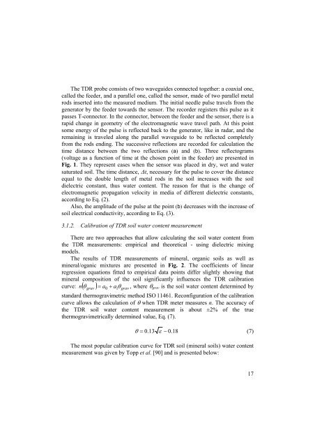
The TDR probe consists of two waveguides connected together: a coaxial one,<br />
called the feeder, and a parallel one, called the sensor, made of two parallel metal<br />
rods inserted into the measured medium. The initial needle pulse travels from the<br />
generator by the feeder towards the sensor. The recorder registers this pulse as it<br />
passes T-connector. In the connector, between the feeder and the sensor, there is a<br />
rapid change in geometry of the electromagnetic wave travel path. At this point<br />
some energy of the pulse is reflected back to the generator, like in radar, and the<br />
remaining is traveled along the parallel waveguide to be reflected completely<br />
from the rods ending. The successive reflections are recorded for calculation the<br />
t<strong>im</strong>e distance between the two reflections (a) and (b). Three reflectograms<br />
(voltage as a function of t<strong>im</strong>e at the chosen point in the feeder) are presented in<br />
Fig. 1. They represent cases when the sensor was placed in dry, wet and water<br />
saturated soil. The t<strong>im</strong>e distance, ∆t, necessary for the pulse to cover the distance<br />
equal to the double length of metal rods in the soil increases with the soil<br />
dielectric constant, thus water content. The reason for that is the change of<br />
electromagnetic propagation velocity in media of different dielectric constants,<br />
according to Eq. (2).<br />
Also, the amplitude of the pulse at the point (b) decreases with the increase of<br />
soil electrical conductivity, according to Eq. (3).<br />
3.1.2. Calibration of TDR soil water content measurement<br />
There are two approaches that allow calculating the soil water content from<br />
the TDR measurements: empirical and theoretical - using dielectric mixing<br />
models.<br />
The results of TDR measurements of mineral, organic soils as well as<br />
mineral/oganic mixtures are presented in Fig. 2. The coefficients of linear<br />
regression equations fitted to empirical data points differ slightly showing that<br />
mineral composition of the soil significantly influences the TDR calibration<br />
n = a a θ , where θ grav is the soil water content determined by<br />
curve: ( θ grav ) 1 grav<br />
0 +<br />
standard thermograv<strong>im</strong>etric method ISO 11461. Reconfiguration of the calibration<br />
curve allows the calculation of θ when TDR meter measures n. The accuracy of<br />
the TDR soil water content measurement is about ±2% of the true<br />
thermograv<strong>im</strong>etrically determined value, Eq. (7).<br />
θ = 0.13<br />
ε − 0.18<br />
(7)<br />
The most popular calibration curve for TDR soil (mineral soils) water content<br />
measurement was given by Topp et al. [90] and is presented below:<br />
17