Care and Maintenance of Robertshaw 41-400 and 41-200 Ignitors
Care and Maintenance of Robertshaw 41-400 and 41-200 Ignitors
Care and Maintenance of Robertshaw 41-400 and 41-200 Ignitors

Create successful ePaper yourself
Turn your PDF publications into a flip-book with our unique Google optimized e-Paper software.
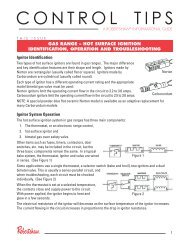
CONTROL TIPS<br />
A ROBERTSHAW ® INFORMATIONAL GUIDE<br />
THIS ISSUE<br />
CARE AND MAINTENANCE OF THE ROBERTSHAW<br />
<strong>41</strong>-<strong>400</strong> <strong>and</strong> <strong>41</strong>-<strong>200</strong> SERIES NORTON IGNITORS<br />
The <strong>Robertshaw</strong> ignitor by Norton is made <strong>of</strong> high-purity Crystar ® recrystallized silicon carbide. Crystar<br />
is a proprietary Norton advanced ceramic that combines physical <strong>and</strong> thermal strength with stable<br />
electrical properties. Ignitor leads are enclosed with a high-temperature fiberglass insulation which<br />
provides total electrical protection. The ignitor is cemented in a steatite or cordierite block for protection<br />
against current leakage under high humidity conditions. Norton ignitors are engineered for easy<br />
h<strong>and</strong>ling, simple installation, <strong>and</strong> trouble-free operation.<br />
Installing the Ignitor<br />
The silicon carbide element can be h<strong>and</strong>led without damage. However, it is better <strong>and</strong> safer to h<strong>and</strong>le the<br />
ignitor by the ceramic holder. The myth that the silicon carbide tip cannot be h<strong>and</strong>led because body oils<br />
cause contamination is untrue.<br />
• Cracks may occur by hitting the silicon carbide tip or dropping the ignitor.<br />
• Check the appearance <strong>of</strong> the ignitor. The sleeving over the wire should be examined for chafing,<br />
burned portions, or cuts in the wire. The connectors should be properly seated <strong>and</strong> free from<br />
oxidation <strong>and</strong>/or corrosion.<br />
• <strong>Care</strong>fully tighten the mounting screw firmly when installing the ignitor. WARNING: Overtightening<br />
may crack the ceramic block. Maximum torque on the ceramic block is 12 inch pounds.<br />
• 501 RANGE IGNITOR ONLY: The ignitor <strong>and</strong> valve must be calibrated to ensure proper performance.<br />
Current must reach the given specifications in order to supply adequate ignition temperature to open<br />
the gas valve. Check to be sure the proper valve is used.<br />
CAUTION: The use <strong>of</strong> the 601 mini-ignitor as a flame sense is the sole responsibility <strong>of</strong> the user/OEM to<br />
engineer, test, <strong>and</strong> approve. If it is determined to be used as a flame sense, then the user/OEM assumes<br />
all risks. Norton Company does not recommend the use <strong>of</strong> the ignitor as a flame sense.<br />
1
Testing the Ignitor<br />
• Perform a simple room temperature resistance (RTR) test after installing a new ignitor. (Remember to<br />
disconnect the leads to ensure that only the resistance <strong>of</strong> the ignitor is measured.) If the RTR is not to<br />
specification (see Ignitor Specifications, below), the silicon carbide tip is cracked.<br />
• Perform an RTR test when troubleshooting an appliance where the ignitor is suspect. While the RTR<br />
will be higher on a used ignitor, the resistance should be no more than double the original resistance<br />
at installation.<br />
• Observe the ignitor during heat up. If a bright white line across one <strong>of</strong> the ignitor legs is detected, a<br />
crack may exist that could cause premature failure. Allow the ignitor to cool, then perform an RTR<br />
test.<br />
• Additional signs <strong>of</strong> a crack are an “open” ignitor or a buildup <strong>of</strong> white silica dust around the bright<br />
spot. Replace the ignitor if you see these cracks.<br />
• Maximum ambient temperature <strong>of</strong> wire/element connection within block is 905°F/485°C when 450°C<br />
wire is used.<br />
Caution should be exercised to assure temperature does not exceed the<br />
recommended maximums.<br />
Ignitor Specifications<br />
Market <strong>and</strong> Ignitor<br />
Model Number<br />
Heating<br />
201<br />
Heating<br />
271<br />
Time<br />
Temperature<br />
Temperature Range Steady State Current Cold<br />
Resistance<br />
34 seconds Minimum 1800°F/985°C @ 102V<br />
Maximum 3100°F/1705°C @ 132V<br />
Typical 2<strong>400</strong>-2600°F / 1315°C-1430°C @ 120V<br />
17 seconds Minimum 1800°F/985°C @ 102V<br />
Maximum 3100°F/1705°C @ 132V<br />
Typical 2<strong>400</strong>-2600°F / 1315°C-1430°C @ 120V<br />
4.25-4.75 Amps @ 132V 45-<strong>400</strong> Ohms<br />
4.25-4.75 Amps @ 132V 40-75 Ohms<br />
Heating<br />
601<br />
Dryer<br />
101<br />
5 seconds Minimum 1800°F/985°C @ 102V<br />
Maximum 2875°F/1580°C @ 132V<br />
Typically 30<br />
seconds<br />
Minimum 1800°F/985°C @ 80V<br />
Maximum 3100°F/1705°C @ 132V<br />
Typical 2<strong>400</strong>-2800°F / 1315°C-1540°C @ 120V<br />
.4-1.0 Amps @ 120V 50-300 Ohms<br />
Maximum 5.0 @ 132V<br />
40-<strong>400</strong> Ohms<br />
Range<br />
501<br />
Maximum 2650°F/1455°C @ 116V<br />
3.2-3.6 Amps @ 116V 50-<strong>400</strong> Ohms<br />
191 E. North Avenue<br />
Carol Stream, IL 60188<br />
www.invensyscontrols.com<br />
©<strong>200</strong>9 Invensys Controls<br />
For Technical Service:<br />
Telephone 1.800.445.8299<br />
Facsimile 1.630.260.7243<br />
technicalservice@invensys.com<br />
Invensys ® <strong>and</strong> <strong>Robertshaw</strong> ® are trademarks <strong>of</strong> Invensys plc., its subsidiaries <strong>and</strong>/or affiliated<br />
companies. All other br<strong>and</strong>s mentioned in this document may be the trademarks <strong>of</strong> their<br />
respective owners. 5/09 – 150-2197