âThe Mimirâ - Intertechnik
âThe Mimirâ - Intertechnik
âThe Mimirâ - Intertechnik

Create successful ePaper yourself
Turn your PDF publications into a flip-book with our unique Google optimized e-Paper software.
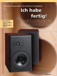
“The Mimir”<br />
Named after Mimir, a primal god of Norse mythology who was renowned for his<br />
knowledge and wisdom, we present a new high-end two-way speaker kit.<br />
The Mimir consist of an 18 cm long throw woofer with a coated paper cone and a<br />
27 mm coated fabric tweeter.<br />
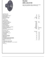
Enclosure and stuffing<br />
The Mimir loudspeaker is based on an enclosure from Madisound Speaker<br />
Components Inc. called MD14BP. This is a 14 litre vented cabinet, made<br />
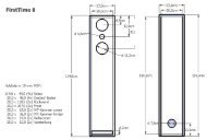
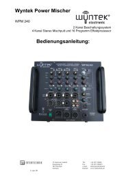
from high grade MDF finished with veneer. Figure 1 shows the cabinet<br />
drawings.<br />
The amount of stuffing and port tuning is based on measurements and extensive<br />
listening. The cabinet is filled with 100 g of Acousto-Q. The stuffing<br />
is placed in the area below the port, to allow free movement of air<br />
around the port opening. The port length is 20 cm including the flanged<br />
end and the inner diameter is 5 cm. This gives a port tuning of 42 Hz<br />
providing a smooth low frequency roll-off, and low airflow noise.<br />
For more information about the Madisound cabinet take a look at their<br />
web:<br />
• Madisound cabinets<br />
Drive units<br />
The woofer used in this system is the SEAS CA18RNX. This is a long throw<br />
18 cm woofer with a coated paper cone. The classical coated paper cone<br />
gives a smooth extended frequency response with a controlled roll off.<br />
The large magnet system gives good transient response, and the bumped
F F<br />
A<br />
200mm (7,87")<br />
115mm (4,5")<br />
E E<br />
D D<br />
C C<br />
A<br />
B B<br />
Date<br />
Designed by Checked by Approved by Date<br />
A A<br />
terje 07.02.2008<br />
CABINET MIMIR<br />
Edition Scale<br />
1:2<br />
8<br />
8<br />
7<br />
7<br />
6<br />
6<br />
5<br />
5<br />
4<br />
4<br />
3<br />
3<br />
2<br />
2<br />
1<br />
1<br />
R5mm (0,2")<br />
R5mm (0,2")<br />
R5mm (0,2")<br />
n104,5mm (4,11")<br />
n76mm (3")<br />
Depth<br />
mm (0,16")<br />
23mm (0,91")<br />
Ø 50 mm (2")<br />
inside tube<br />
295mm (11,61")<br />
390mm (15,35")<br />
n177mm (6,97")<br />
n147mm (5,79")<br />
Depth<br />
mm (0,24")<br />
138mm (5,43")<br />
115mm (4,5")<br />
255mm (10,04")<br />
230mm (9")<br />
4<br />
6<br />
85mm (3,35")<br />
R31mm (1,22")<br />
90mm (3,54")<br />
Adjust hole to<br />
outside tube<br />
Adjust to<br />
terminal<br />
50mm (2")<br />
MATERIAL: 19mm (3/4") MDF
ack plate together with the very long, and light weight copper clad aluminum<br />
voice coil allow for extreme coil excursion with low distortion. The<br />
extremely stiff and stable injection moulded metal basket, keeps the critical<br />
components in perfect alignment. Large windows in the basket both<br />
above and below the spider reduce sound reflection, air flow noise and<br />
cavity resonance to a minimum.<br />
The tweeter is the SEAS 27TDFC. This is a 27 mm High Definition precoated<br />
fabric dome tweeter with a wide, soft polymer surround. The<br />
dome and surround materials give high consistency and excellent stability<br />
against variations in air humidity. The voice coil is wound on an<br />
aluminum voice coil former with adequate ventilating holes to eliminate<br />
noise from internal air flow. The voice coil is immersed in low viscosity<br />
magnetic fluid, for high power handling capacity and simplified crossover<br />
design. A stiff and stable rear chamber with optimal acoustic damping allows<br />
27TDFC to be used with moderately low crossover frequencies. The<br />
chassis is precision moulded from glass fibre reinforced plastic, and its<br />
front design offers optimum radiation conditions.<br />
For detailed technical parameters on the drive units see the data sheet:<br />
• 27TDFC - H1189<br />
• CA18RNX - H1215<br />
Crossover<br />
The crossover is designed in LspCAD from IJData, with the objective to<br />
obtain a simple design without sacrificing the overall quality. Driver response<br />
and impedance were measured with the drivers mounted in the<br />
box at 1 metre distance 15 ◦ off the tweeter axis in an anechoic room. This<br />
reference point was used in the design to minimize the influence of baffle<br />
edge diffraction. By measuring the drivers at the same point it is easy to<br />
simulate the summation of and phase response between the drivers.<br />
The crossover was developed empirically, without confinement to the traditional<br />
textbook filter formulas. The drivers should be in phase at the<br />
crossover frequency, and the sum should be flat when both drivers are<br />
at -6dB relative to the pass band level. Now the inevitable vertical offaxis<br />
cancellation, which is always present with the use of non-coincident<br />
drivers, is at least outside the listening axis (tweeter axis).
To accomplish the design goals it was necessary to use a 2nd order electrical<br />
filter for the high pass section, with an “l-pad” for attenuation because<br />
of the different sensitivities of the drivers. The low pass section was<br />
realised with a 2nd order electrical filter and a baffle-step compensator<br />
consisting of a parallel connection of an inductor and a resistor in series<br />
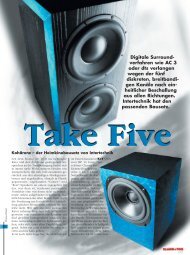
with the driver, thus providing a flat frequency response. The crossover<br />
schematics is shown in figure 2.<br />
Figure 2: Crossover schematics
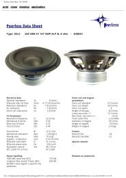
Measurements<br />
The measurements are taken in free field at 1 metre 15 ◦ off tweeter axis.<br />
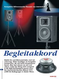
Figure 3 shows the results of the measurements. As seen in the figure the<br />
average sensitivity is 84dB and the response lies within ± 2dB.<br />
Figure 3: Anechoic free field response at 1m 15 ◦ measured at 2.83V.<br />
Impedance measured at 2V.<br />
The black curve shows the response with the tweeter connected with opposite<br />
polarity. In this curve we look for a deep and symmetrical notch<br />
around the crossover frequency, which indicates that the drivers are in<br />
phase in the crossover region. Here the notch is more than 25dB deep, and<br />
that confirms that this system has a very good phase response. The blue<br />
and green curves show respectively the response of the woofer and the<br />
tweeter.<br />
The 2nd order electrical crossover combined with the natural roll-off of the<br />
drivers gives a 4th order acoustical Linkwitz-Riley slope. The crossover<br />
frequency is 2.2 kHz, high enough for the tweeter to operate inside its<br />
limits, even at high amplitudes, and low enough so that the woofer doesn’t<br />
become too directional, and thus providing a smooth power respons.<br />
The off-axis respons of the Mimir is shown in figure 4. This figure shows<br />
that the power response is very smooth throughout the whole frequency
Figure 4: SPL at 1m, 2.83V, on- and off-axis<br />
Figure 5: Harmonic distortion at 12V 96dB SPL 1m on-axis
ange, and the controlled off-axis roll off of the tweeter.<br />
Figure 5 shows the 2nd and 3rd order harmonic distortion with an output<br />
of 96dB at 1m. The overall distortion is very low and without any<br />
peaks that might become noticeable. This makes the reproduced music<br />
very clean and without coloration.