Torque Flange Data Sheet
Torque Flange Data Sheet
Torque Flange Data Sheet

Create successful ePaper yourself
Turn your PDF publications into a flip-book with our unique Google optimized e-Paper software.
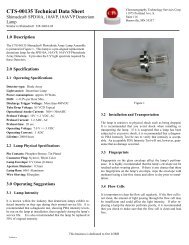
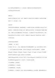
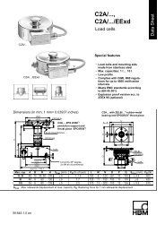
T10FM<br />
<strong>Torque</strong> <strong>Flange</strong><br />
<strong>Data</strong> <strong>Sheet</strong><br />
Special features<br />
− Nominal (rated) torque:<br />
15 kNVm, 20 kNVm, 25 kNVm,<br />
30 kNVm, 40 kNVm, 45 kNVm,<br />
50 kNVm, 60 kNVm, 70 kNVm and<br />
80 kNVm<br />
− Nominal (rated) rotational speed<br />
from 3000 rpm to 8000 rpm<br />
− Short design<br />
− High permissible transverse<br />
forces<br />
− High radial stiffness<br />
− Contactless<br />
− Integral speed measuring<br />
system (optional)<br />
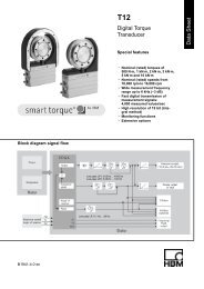
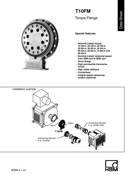
Installation example<br />
Rotor<br />
Stator<br />
Connecting element<br />
e. g. cardan shaft<br />
T10FM<br />
Connecting element<br />
e. g. coupling<br />
B0892-2.1 en
Specifications<br />
Type<br />
Accuracy class 0.1<br />
<strong>Torque</strong> measuring system<br />
T10FM<br />
Nominal (rated) torque M nom kN⋅m 15 20 25 30 40 45 50 60 70 80<br />
for reference only kft−lb 11.25 15 18.75 22.5 30 33.75 37.5 45 52.5 60<br />
Nominal (rated) sensitivity (range between<br />
torque = zero and M nom )<br />
Frequency output<br />
Voltage output<br />
Characteristic tolerance (deviation of the<br />
actual frequency span at M nom from the nominal<br />
(rated) sensitivity)<br />
Frequency output<br />
Voltage output<br />
Output signal at torque = zero<br />
Frequency output<br />
Voltage output<br />
Nominal (rated) output signal<br />
Frequency output<br />
with positive nominal (rated) torque<br />
with negative nominal (rated) torque<br />
Voltage output<br />
with positive nominal (rated) torque<br />
with negative nominal (rated) torque<br />
Limit load resistance<br />
Frequency output<br />
Voltage output<br />
kHz<br />
V<br />
%<br />
%<br />
kHz<br />
V<br />
kHz<br />
kHz<br />
V<br />
V<br />
kΩ<br />
kΩ<br />
5<br />
10<br />
0.2<br />
0.3<br />
10<br />
0<br />
15 (5 V symmetric) 1) / 15 (12 V asymmetric)<br />
5 (5 V symmetric) 1) / 5 (12 V asymmetric)<br />
Long−term drift over 48 h<br />
Voltage output mV < 3<br />
Cut−off frequency<br />
Voltage output −3 dB kHz 1<br />
Group delay time<br />
Frequency output<br />
Voltage output<br />
ms<br />
ms<br />
Residual ripple<br />
Voltage output mV 40 (Peak/Peak)<br />
Temperature influence per 10 K in the<br />
nominal (rated) temperature range<br />
on the output signal, related to the actual<br />
value of signal span<br />
Frequency output<br />
Voltage output<br />
on the zero signal, related to the<br />
nominal (rated) sensitivity<br />
Frequency output<br />
Voltage output<br />
Maximum modulation range 2)<br />
Frequency output<br />
Voltage output<br />
Power supply<br />
%<br />
%<br />
%<br />
%<br />
kHz<br />
V<br />
+10<br />
−10<br />
> 2<br />
> 5<br />
0.15<br />
0.9<br />
Specifications (Continued)<br />
Nominal (rated) torque M nom kN⋅m 15 20 25 30 40 45 50 60 70 80<br />
for reference only kft−lb 11.25 15 18.75 22.5 30 33.75 37.5 45 52.5 60<br />
Linearity deviation including hysteresis,<br />
related to the nominal (rated) sensitivity<br />
Frequency output<br />
Voltage output<br />
Rel. standard deviation of the repeatability,<br />
according to DIN1319, by reference to variation<br />
of the output signal<br />
%<br />
%<br />
%<br />
Specifications (Continued)<br />
Nominal (rated) torque M nom kN⋅m 15 20 25 30 40 45 50 60 70 80<br />
for reference only kft−lb 11.25 15 18.75 22.5 30 33.75 37.5 45 52.5 60<br />
Reference temperature °C [°F] +23 [73.4]<br />
Nominal (rated) temperature range °C [°F] +10 ... +60 [+50 ... +140]<br />
Service temperature range °C [°F] −10 ... +60 [+14 ... +140]<br />
Storage temperature range °C [°F] −20 ... +70 [−4 ... +158]<br />
Impact resistance, test severity level<br />
to IEC 68−2−27−1987<br />
Number of impacts n 1000<br />
Duration ms 3<br />
Acceleration (half−sine) m/s 2 650<br />
Vibration resistance, test severity level<br />
to IEC 68−2−6−1982<br />
Frequency range Hz 5 ... 65<br />
Duration h 1.5<br />
Acceleration (amplitude) m/s 2 50<br />
Nominal (rated) rotational speed rpm 6000 4000 3000<br />
Nominal (rated) rotational speed optional rpm 8000 6000 4500<br />
Load limits 5)<br />
Limit torque kN⋅m 32 60 110<br />
Breaking torque kN⋅m > 50 > 90 > 160<br />
Axial limit force kN 60 120 240<br />
Lateral limit force kN 80 160 240<br />
Bending limit moment N⋅m 6000 12000 24000<br />
Oscillation bandwidth according to<br />
kN⋅m 25 45 80<br />
DIN 50100 (peak-to-peak)<br />
upper maximum torque kN⋅m + 20 + 40 + 70<br />
lower maximum torque kN⋅m − 20 − 40 − 70<br />
Mechanical data<br />
Torsional stiffness c T kN⋅m/rad 14500 34000 60000<br />
Torsion angle M nom degree 0.06 0.08 0.1 0.05 0.065 0.075 0.05 0.06 0.07 0.08<br />
Axial stiffness c a kN/mm 1250 1500 2200<br />
Radial stiffness c r kN/mm 1800 2500 3600<br />
Stiffness with bending moment about a<br />
radial axis c b kN⋅m/rad 3300 7400 14800<br />
Maximum excursion at axial limit force mm < 0.05 < 0.08 < 0.12<br />
Additional max. concentricity error at lateral<br />
limit force mm < 0.05 < 0.07 < 0.1<br />
Additional plane-parallel deviation at bending<br />
limit moment mm 0.5<br />
Balance quality-level to DIN ISO 1940 G 6.3<br />
Max. limits for relative shaft vibration<br />
(peak-to-peak) 6) µm s max 4500<br />
n<br />
(n in rpm)<br />
Mass moment of inertia of the rotor L V<br />
(about axis of rotation) kg⋅m 2 0.3 0.7 1.1<br />
Proportional mass moment of inertia<br />
(<strong>Flange</strong> A) % 70<br />
Max. permissible static eccentricity<br />
of the rotor (radially)<br />
without speed measuring system<br />
with speed measuring system<br />
Permissible axial displacement<br />
between rotor and stator<br />
without speed measuring system<br />
with speed measuring system<br />
mm<br />
mm<br />
mm<br />
mm<br />
5) Each type of irregular stress can only be permitted with its given static limit values (bending moment, lateral or axial load, exceeding the<br />
nominal (rated) torque) if none of the others can occur. Otherwise the limit values must be reduced. If for instance 30 % of the bending limit<br />
moment and also 30 % of the lateral limit force are present, only 40 % of the axial limit force are permitted, provided that the nominal (rated)<br />
torque is not exceeded.<br />
With the permitted bending moments, axial, and lateral limit forces, measuring errors of about 1 % of the nominal (rated) torque can occur. If<br />
the nominal (rated) torque has been exceeded, the signal output electronics’ maximum modulation range must be taken into account.<br />
6) Relative undulations within the range of the connecting flanges in accordance with DIN 45670/VDI 2059<br />
2<br />
1<br />
3<br />
2<br />
HBM 4<br />
B0892-2.1 en
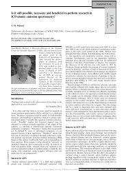
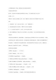
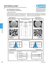
DimensionsT10FM without speed measuring system<br />
View Y<br />
9<br />
10<br />
20<br />
190<br />
b<br />
approx. 3<br />
b2<br />
b1<br />
N<br />
O<br />
øP<br />
Thread Y turned<br />
in the cutting<br />
place<br />
øQ<br />
a<br />
View X<br />
ød<br />
ødA<br />
b<br />
Thread Y<br />
L max<br />
X<br />
H3 max.<br />
H2<br />
ødB<br />
ødza<br />
K<br />
ø20<br />
ødzi<br />
h<br />
H1<br />
ødE<br />
<strong>Flange</strong> A<br />
ødC<br />
ødF<br />
22<br />
50<br />
M<br />
Xs<br />
77<br />
52.5<br />
150<br />
+2<br />
+2<br />
210<br />
52.5<br />
Y<br />
x S = Measurement plane (centre of point of application)<br />
Measuring<br />
range<br />
(kNVm)<br />
15<br />
20<br />
25<br />
30<br />
40<br />
45<br />
50<br />
60<br />
70<br />
80<br />
Measuring<br />
range<br />
(kNVm)<br />
15<br />
20<br />
25<br />
30<br />
40<br />
45<br />
50<br />
60<br />
70<br />
80<br />
Dimensions in mm<br />
h H1 H2 H3 b b1 b2 ∅d ∅dA ∅dB ∅dC ∅dE ∅dF ∅dza K<br />
226.5 373 423 437 28.5 59 73 262 256 206 288 237.15 326 174 g5 3<br />
248 416 466 480 35 69 85 305 299 250 350 280.15 390 210 g5 4<br />
263 446 495 509 40 74 95 335 329 275 385 310.15 425 240 g5 4<br />
Dimensions in mm<br />
∅dzi L max M N O P Q x S a b Y<br />
174 H6 4 38 34.5 19.5 30 19 24<br />
210 H6 4 44 40 21.5 33 21 26<br />
240 H6 4 49 45 23.5 36 23 29<br />
22.5°<br />
16x22.5°=360°<br />
15°<br />
24x15°=360°<br />
15°<br />
24x15°=360°<br />
11.25°<br />
16x22.5°=360°<br />
15°<br />
24x15°=360°<br />
15°<br />
24x15°=360°<br />
M18 x 2.5<br />
M20 x 2.5<br />
M22 x 2.5<br />
B0892-2.1 en<br />
5<br />
HBM
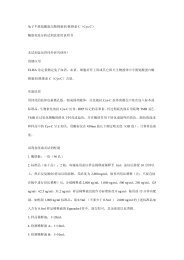
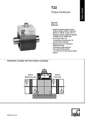
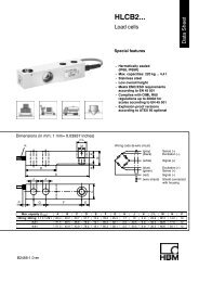
Dimensions T10FM with speed measuring system<br />
View Y<br />
View X<br />
9<br />
10<br />
20<br />
190<br />
b<br />
Through hole<br />
X<br />
H3 max.<br />
Slotted disc<br />
0.3 thick<br />
(mounted by<br />
customer)<br />
H2<br />
H1<br />
øds<br />
Thread Y turned<br />
in the cutting<br />
place<br />
Thread Y<br />
Fixing bolts<br />
of the<br />
slotted disc<br />
h<br />
ød<br />
ødA<br />
e<br />
ødB<br />
approx. 3<br />
ødza<br />
K<br />
c<br />
b2<br />
b1<br />
N<br />
O<br />
ø P<br />
<strong>Flange</strong> A<br />
øQ<br />
Lmax<br />
ødzi<br />
ødE<br />
ødC<br />
ødF<br />
a<br />
b<br />
Additional disc<br />
for slotted disc<br />
mounting<br />
22<br />
50<br />
M<br />
Xs<br />
77<br />
52.5<br />
29.5<br />
150 +2<br />
210 +2<br />
∅20<br />
52.5<br />
Y<br />
x S = Measurement plane (centre of point of application)<br />
Measuring<br />
range<br />
(kNVm)<br />
15<br />
20<br />
25<br />
30<br />
40<br />
45<br />
50<br />
60<br />
70<br />
80<br />
Measuring<br />
range<br />
(kNVm)<br />
15<br />
20<br />
25<br />
30<br />
40<br />
45<br />
50<br />
60<br />
70<br />
80<br />
Dimensions in mm<br />
h H1 H2 H3 b b1 b2 ∅d ∅dA ∅dB ∅dC ∅dE ∅dF ∅dza K ∅dzi L max<br />
226.5 373 423 437 28.5 59 73 262 256 206 288 237.15 326 174 g5 3 174 H6 4<br />
248 416 466 480 35 69 85 305 299 250 350 280.15 390 210 g5 4 210 H6 4<br />
263 446 495 509 40 74 95 335 329 275 385 310.15 425 240 g5 4 240 H6 4<br />
Dimensions in mm<br />
∅d S c e M N O P Q x S a b Y<br />
269 16.5 19.5 38 34.5 19.5 30 19 24<br />
312 14.5 21.5 44 40 21.5 33 21 26<br />
342 9.5 23.5 49 45 23.5 36 23 29<br />
22.5°<br />
16x22.5°=360°<br />
15°<br />
24x15°=360°<br />
15°<br />
24x15°=360°<br />
11.25°<br />
16x22.5°=360°<br />
15°<br />
24x15°=360°<br />
15°<br />
24x15°=360°<br />
M18 x 2.5<br />
M20 x 2.5<br />
M22 x 2.5<br />
HBM 6<br />
B0892-2.1 en
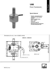
Flatness and concentricity tolerances<br />
Area free of metal parts<br />
Mounting dimensions<br />
0.04 AB<br />
B<br />
A<br />
a<br />
a<br />
Measuring<br />
range<br />
(kNVm)<br />
Area free of<br />
metal parts *)<br />
”a”<br />
(mm)<br />
0.04 AB<br />
Internal centering<br />
Identification<br />
plate of the<br />
rotor<br />
∅d E<br />
15<br />
20<br />
25<br />
30<br />
40<br />
45<br />
20<br />
50<br />
60<br />
70<br />
80<br />
Identification plate of the stator<br />
<strong>Flange</strong> A<br />
<strong>Flange</strong> B<br />
0,8<br />
Hardness 46 ... 54 HRC<br />
Surface quality of in−plane and concentric<br />
surfaces (A, B and AB)<br />
*) Support using a metal bar with the<br />
recommended dimensions is<br />
permissible.<br />
Screw fitting of the rotor<br />
Hexagon socket screw (Z)<br />
DIN EN ISO 4762<br />
<strong>Flange</strong> A<br />
Fastening screw; the maximum thread depth Y must<br />
in any case be observed!<br />
Measuring<br />
range<br />
(NVm)<br />
Fastening Fastening screws class Maximum thread depth (Y)<br />
screws (Z) 1) (mm)<br />
Prescribed fastening<br />
torque<br />
(NVm)<br />
15/20/25 M18x2.5<br />
30 400<br />
30/40/45 M20x2.5 10.9<br />
40 560<br />
50/60/70/80 M22x2.5 45 760<br />
1) DIN EN ISO 4762; bk/oiled/m tot =0.125<br />
B0892-2.1 en<br />
7<br />
HBM
Ordering number<br />
Code<br />
015R<br />
020R<br />
025R<br />
030R<br />
040R<br />
045R<br />
050R<br />
060R<br />
070R<br />
080R<br />
Option 1: Measuring range<br />
15 kN⋅m<br />
20 kN⋅m<br />
25 kN⋅m<br />
30 kN⋅m<br />
40 kN⋅m<br />
45 kN⋅m<br />
50 kN⋅m<br />
60 kN⋅m<br />
70 kN⋅m<br />
80 kN⋅m<br />
Code<br />
Option 2: Electrical configuration<br />
SU2 Output signal 10 kHz 5 kHz and 10 V,<br />
Supply voltage 18...30 V DC<br />
Code<br />
Option 4: Speed measuring system<br />
0 Without speed measuring system<br />
1 With speed measuring system<br />
Code<br />
S<br />
H<br />
Option 5: Customer-specific modification<br />
None<br />
Higher nominal (rated) rotational speed, depending on<br />
measuring range 4500 min −1 up to 8000 min −1<br />
Code<br />
S<br />
<<br />
G<br />
<<br />
Option 3: Accuracy<br />
Linearity deviation including hysteresis<br />