Torque transducer Data sheet
Torque transducer Data sheet
Torque transducer Data sheet

You also want an ePaper? Increase the reach of your titles
YUMPU automatically turns print PDFs into web optimized ePapers that Google loves.
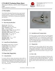
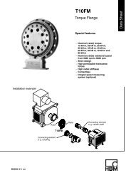
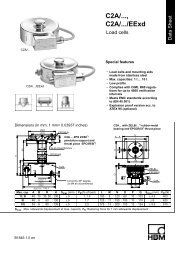
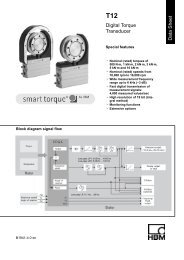
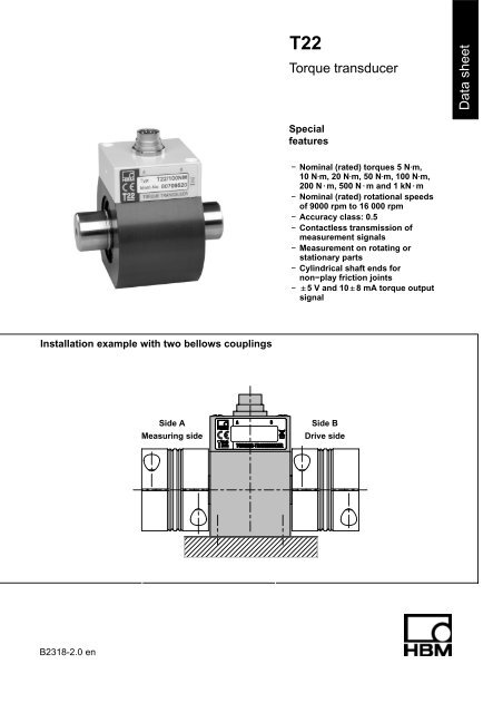
T22<br />
<strong>Torque</strong> <strong>transducer</strong><br />
<strong>Data</strong> <strong>sheet</strong><br />
Special<br />
features<br />
− Nominal (rated) torques 5 NVm,<br />
10 NVm, 20 NVm, 50 NVm, 100 NVm,<br />
200 N@m, 500 N@m and 1 kN@m<br />
− Nominal (rated) rotational speeds<br />
of 9000 rpm to 16 000 rpm<br />
− Accuracy class: 0.5<br />
− Contactless transmission of<br />
measurement signals<br />
− Measurement on rotating or<br />
stationary parts<br />
− Cylindrical shaft ends for<br />
non−play friction joints<br />
− "5 V and 10"8 mA torque output<br />
signal<br />
Installation example with two bellows couplings<br />
Side A<br />
Measuring side<br />
Side B<br />
Drive side<br />
B2318-2.0 en
Specifications<br />
Type<br />
Accuracy class 0.5<br />
<strong>Torque</strong> measuring system<br />
Nominal (rated) torque M nom N⋅m 5 10 20 50 100 200 500<br />
kN⋅m 1<br />
T22<br />
Nominal (rated) sensitivity (span between<br />
torque = zero and nominal (rated) torque M nom )<br />
Voltage output<br />
Current output<br />
Sensitivity tolerance (deviation of the actual output<br />
quantity at M nom from the nominal (rated) sensitivity)<br />
Voltage output<br />
Current output<br />
Output signal at torque = zero<br />
Voltage output<br />
Current output<br />
Nominal (rated) output signal<br />
Voltage output<br />
at positive nominal (rated) torque<br />
at negative nominal (rated) torque<br />
Current output<br />
at positive nominal (rated) torque<br />
at negative nominal (rated) torque<br />
V<br />
mA<br />
%<br />
%<br />
V<br />
mA<br />
V<br />
V<br />
mA<br />
mA<br />
5<br />
8<br />
0.2<br />
0.2<br />
00.2<br />
100.2<br />
Load resistance (Voltage output) MΩ >1<br />
Burden (current output)<br />
with U B = 12 V<br />
with U B = 24 V<br />
Longterm drift over 48h<br />
Voltage output<br />
Current output<br />
Cut−off frequency (−3 dB) (volt. output / current output) kHz 1<br />
Ω<br />
Ω<br />
mV<br />
mA<br />
+5<br />
−5<br />
+18<br />
+2<br />
250<br />
500<br />
Specifications (continued)<br />
Nominal (rated) torque M nom N⋅m 5 10 20 50 100 200 500<br />
kN⋅m 1<br />
General data<br />
EMC 2)<br />
Immunity from interference<br />
(DIN EN 61326−1 / EN 61000−6)<br />
Enclosure<br />
HF line interference<br />
150 kHZ − 80 MHz (AM)<br />
ESD (electrostatic discharge)<br />
Enclosure<br />
Electromagnetic field<br />
80 MHz − 1000 MHz (AM)<br />
1400 MHz − 2700 MHz (AM)<br />
V<br />
kV<br />
kV<br />
V/m<br />
V/m<br />
10 / A<br />
Air 8 / A<br />
Contact 4 / A<br />
10 / A<br />
3 / A<br />
Lines − Connecting cable<br />
Burst (fast transients) kV 2 / A<br />
Emission (EME) (EN 61326-1 / EN 55011)<br />
RFI voltage<br />
(interference voltage at DC mains connection)<br />
RFI field strength<br />
−<br />
−<br />
Class B (150 kHz − 30 MHz)<br />
Class B (30 MHz − 1000 MHz)<br />
(Electromagnetic RFI field strength)<br />
Degree of protection per EN 60529 IP 40<br />
Nominal (rated) temperature range °C [°F] +5...+45 [+41...+113]<br />
Operating temperature range °C [°F] 0...+60 [+32...+140]<br />
Storage temperature range °C [°F] −5...+70 [+23...+158]<br />
Impact resistance, test severity level per<br />
DIN IEC 68; Part 2-27; IEC 68-2-29-1987<br />
number n 1000<br />
duration ms 3<br />
acceleration (halfsine) m/s 2 650<br />
Vibration resistance, test severity level<br />
per DIN IEC 68, Part 2-6: IEC 68-2-6-1982<br />
frequency range Hz 5 ... 65<br />
duration h 1.5<br />
acceleration (amplitude) m/s 2 50<br />
Nominal (rated) rotational speed n nom min -1 16 000 12 000 9 000<br />
Load limits 3)<br />
Limit torque, related to M nom % 200 5)<br />
Breaking torque, related to M nom % > 280<br />
Longitudinal limit force kN 0.9 0.9 0.9 1.6 1.6 1.6 4 4<br />
Lateral limit force N 25 45 90 210 420 850 1400 2800<br />
Bending limit moment N⋅m 0.5 0.9 1.9 5.5 11 22 54 109<br />
Oscillation width per DIN 50100 (peak-topeak)<br />
4) %<br />
80<br />
2) Test severity / criterion: Industrial environment, cable length 30 m. Application not outside buildings.<br />
3) Each type of irregular stress (bending moment, lateral or longitudinal force, exceeding nominal (rated) torque) can only be permitted up to its<br />
specified static load limit provided none of the others can occur at the same time. If this condition is not met, the limit values must be<br />
reduced. If 30% of the bending limit moment and lateral limit force occur at the same time, only 40% of the longitudinal limit force is<br />
permissible and the nominal (rated) torque must not be exceeded. The permissible bending moments, longitudinal forces and lateral forces<br />
can affect the measurement result by approx. 1 % of the nominal (rated) torque.<br />
4) The nominal (rated) torque must not be exceeded.<br />
5) Please adhere to the maximum torque (T max ) of the couplings.<br />
B2318-2.0 en<br />
3<br />
HBM
Specifications (continued)<br />
Nominal (rated) torque M nom N⋅m 5 10 20 50 100 200 500<br />
kN⋅m 1<br />
Mechanical values<br />
Torsional stiffness c T<br />
kN⋅m/<br />
rad<br />
1.1 2.7 5.4 19.7 35.5 52.4 288.6 418.9<br />
Torsion angle at M nom Deg. 0.26 0.21 0.21 0.15 0.16 0.22 0.10 0.14<br />
Max. limits for relative shaft vibration (peaktopeak)<br />
6) µm s max 4500<br />
n<br />
Rms value for the vibration velocity of the enclosure<br />
designated in VDI 2056<br />
Mass moment of inertia<br />
total<br />
drive side of shaft<br />
measuring side of shaft<br />
mm/s<br />
v eff <br />
n 3<br />
(n in rpm)<br />
(n in rpm)<br />
10 −3 13.4 13.5 13.6 39.8 40.5 42.4 335.0 351.9<br />
g⋅m 2 11.6 11.7 11.7 29.2 29.6 30.5 187.9 196.3<br />
1.8 1.8 1.9 10.6 10.9 11.9 147.1 155.6<br />
Weight g 350 600 2000<br />
6) Relative undulation in the area of the connecting shaft stubs, following DIN 45670/VDI 2059<br />
HBM 4<br />
B2318-2.0 en
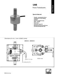
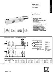
Dimensions of the T22<br />
a<br />
b<br />
63<br />
∅17.2<br />
70<br />
e<br />
c<br />
f<br />
e<br />
∅d 2<br />
l<br />
∅d 1<br />
∅d 1<br />
g<br />
h (k)<br />
(13)<br />
Y<br />
x<br />
Measuring<br />
side<br />
Measuring<br />
Dimensions (in mm)<br />
range<br />
(N⋅m)<br />
a b c e f g h (k) l ∅d 1 g6 ∅d 2 0,1 Y X<br />
5<br />
10 39 31 80 15 48 72 28 44 52.75 15 70 M4 6<br />
20<br />
50<br />
100 42 35 90 18 52 77.5 30 47.5 53 24 75 M4 6<br />
200<br />
500<br />
1k<br />
50 55 120 26 65 97.5 40 57.5 75.5 40 105 M5 10<br />
B2318-2.0 en<br />
5<br />
HBM
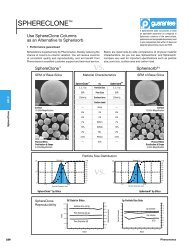
Bellows couplings<br />
G<br />
A<br />
C<br />
∅D 2<br />
H7<br />
Customer side<br />
∅B<br />
F<br />
E<br />
∅D 1<br />
H7<br />
<strong>Torque</strong> <strong>transducer</strong><br />
L<br />
A<br />
(K)<br />
(K)<br />
A<br />
T22 with mounted couplings<br />
Dimensions<br />
Dimensions (in mm)<br />
Measuring range Part no. A jB C jD 1 jD 2 E F G L (K)<br />
(N⋅m)<br />
variable<br />
from−to<br />
5<br />
10 3-4412.0020 40 49 16.5 15 15−28 M5 17 6 130 1<br />
20<br />
50<br />
100 3-4412.0021 59 66 23 24 24−35 M8 23 9.5 172 1<br />
200<br />
500<br />
1k<br />
3-4412.0022 89 110 34 40 40−60 M12 39 13 246 1.5<br />
When ordering, please specify: connection holes D 2 as requested by the customer within specified limits; boring<br />
tolerance H7.<br />
B2318-2.0 en<br />
6<br />
HBM
Specifications<br />
Measuring<br />
range<br />
<strong>Torque</strong><br />
coupling<br />
T Kmax<br />
Mass<br />
moment<br />
of inertia<br />
Weight<br />
Torsional<br />
stiffness<br />
(N⋅m) (N⋅m) (10 −3<br />
kg⋅m 2) (kg) (kN⋅m/rad) axial<br />
(mm)<br />
Max. permissible offset Spring stiffness Material<br />
hub and fixing<br />
ring<br />
radial<br />
(mm)<br />
angular<br />
(degree)<br />
axial<br />
(N/mm)<br />
radial<br />
(N/mm)<br />
Tightening<br />
torque for<br />
clamping<br />
bolts<br />
(N⋅m)<br />
5<br />
10 20 0.05 0.13 41.9 1.0 0.06 0.5 55.8 3710<br />
8<br />
20<br />
50<br />
aluminum<br />
100 200 0.18 0.4 138 1.0 0.08 0.5 153 11000 40<br />
200<br />
500<br />
1k<br />
1000 7.2 4.0 1210 1.5 0.1 0.5 148 9010 steel 130<br />
General instructions<br />
• Only tighten the clamping bolts of the couplings when the shafts are mounted in the coupling hubs!<br />
• The bellows coupling must not be overstretched beyond the specified permissible flexibility limits.<br />
• Drive and output shafts must be free from grease and burrs.<br />
• Implement a tolerance of j6 for the shaft diameter, to produce the preferred fit of H7/j6.<br />
Mounting position<br />
The T22 torque <strong>transducer</strong> can be operated with bellows couplings in any mounting position (horizontally, vertically or<br />
at an angle). When mounting vertically or at an angle, please make sure that the additional elements are adequately<br />
supported.<br />
Delivery condition<br />
The couplings and the torque <strong>transducer</strong> are delivered as separate items.<br />
HBM 7<br />
B2318-2.0 en
Accessories for the T22, to be ordered separately<br />
Transducer connection cable, 5 m long, order no. 3-3301.0158<br />
Transducer connection cable, 10 m long, order no. 3-3301.0159<br />
Cable socket, 12−pin (Binder), order no. 3-3312.0268<br />
Bellows couplings<br />
Junction box, order no. 1-VK20A<br />
Accessories for junction box VK20A, to be ordered sparately<br />
Connection cable, 1.5 m long (D−Sub, 15−pin − free ends), order no. 1-Kab151-1.5<br />
Connection cable, 1.5 m long (SUBCON5 − free ends), order no. 1-Kab152-1.5<br />
Modifications reserved.<br />
All details describe our products in general form only.<br />
They are not to be understood as a guarantee of quality<br />
or durability and do not constitute any liability whatsoever.<br />
B2318-2.0 en<br />
Hottinger Baldwin Messtechnik GmbH<br />
Postfach 10 01 51, D-64201 Darmstadt, Germany<br />
Im Tiefen See 45, D−64293 Darmstadt, Germany<br />
Tel.: +49 6151 803-0 Fax: +49 6151 803 9100<br />
E−mail: support@hbm.com Internet: www.hbm.com