Digital Torque Transducer Data Sheet
Digital Torque Transducer Data Sheet
Digital Torque Transducer Data Sheet

Create successful ePaper yourself
Turn your PDF publications into a flip-book with our unique Google optimized e-Paper software.
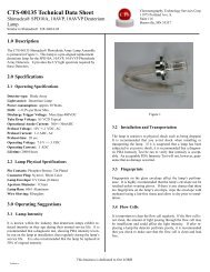
T12<br />
<strong>Digital</strong> <strong>Torque</strong><br />
<strong>Transducer</strong><br />
<strong>Data</strong> <strong>Sheet</strong><br />
Special features<br />
− Nominal (rated) torques of<br />
500 NVm, 1 kNVm, 2 kNVm, 3 kNVm,<br />
5 kNVm and 10 kNVm<br />
− Nominal (rated) speeds from<br />
10,000 rpm to 16,000 rpm<br />
− Wide measurement frequency<br />
range up to 6 kHz (−3 dB)<br />
− Fast digital transmission of<br />
measurement signals:<br />
4,800 measured values/sec<br />
− High resolution of 19 bit (integral<br />
method)<br />
− Monitoring functions<br />
− Extensive options<br />
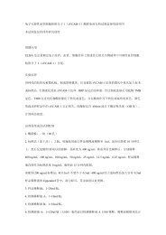
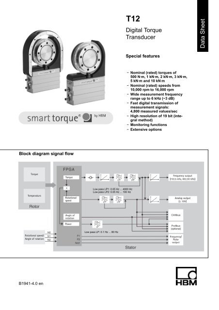
Block diagram signal flow<br />
Low pass LP1: 0.05 Hz ... 4000 Hz<br />
Low pass LP2: 0.05 Hz ... 100 Hz<br />
Low pass LP: 0.1 Hz ... 80 Hz<br />
B1941-4.0 en
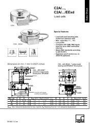
Specifications<br />
Type<br />
T12<br />
Accuracy class 0.03<br />
<strong>Torque</strong> measuring system<br />
N⋅m 500<br />
Nominal (rated) torque M nom<br />
kN⋅m 1 2 3 5 10<br />
for reference only kft-lb 375 750 1,500 2,250 3,750 7,500<br />
Nominal (rated) sensitivity (range between torque =<br />
zero and M nom )<br />
Frequency output 10 kHz/60 kHz<br />
Voltage output<br />
Sensitivity tolerance (deviation of the actual output<br />
quantity at M nom from the nominal (rated) sensitivity)<br />
Fieldbusses<br />
Frequency output<br />
Voltage output<br />
Output signal at torque = zero<br />
Frequency output 10 kHz/60 kHz<br />
Voltage output<br />
Nominal (rated) output signal<br />
Frequency output<br />
with positive nominal (rated) torque 10 kHz/60 kHz<br />
with negative nominal (rated) torque 10 kHz/60 kHz<br />
Voltage output<br />
with positive nominal (rated) torque<br />
with negative nominal (rated) torque<br />
Low-pass filter LP1<br />
Low-pass filter LP2<br />
Load resistance<br />
Frequency output<br />
Voltage output<br />
kHz<br />
V<br />
%<br />
%<br />
%<br />
kHz<br />
V<br />
kHz<br />
kHz<br />
V<br />
V<br />
Hz<br />
Hz<br />
kΩ<br />
kΩ<br />
5/30<br />
10<br />
0.05<br />
0.05<br />
0.1<br />
10/60<br />
0<br />
15/90 (5 V symmetric 1) )<br />
5/30 (5 V symmetric 1) )<br />
+10<br />
−10<br />
0.05 ... 4,000 (4 th order Bessel, −1 dB); factory settings 1,000 Hz<br />
0.05 ... 100 (4 th order Bessel, −1 dB); factory settings 1 Hz<br />
Long-term drift over 48 h<br />
Voltage output mV 3<br />
Measurement frequency range<br />
Frequency output/Voltage output<br />
Group delay time (Low pass LP1: 4 kHz)<br />
Frequency output 10 kHz/60 kHz<br />
Voltage output<br />
Hz<br />
Hz<br />
ms<br />
ms<br />
≥ 2<br />
≥ 10<br />
0 ... 4,000 (−1 dB)<br />
0 ... 6,000 (−3 dB)<br />
320/250<br />
500<br />
Scale range<br />
Frequency output/Voltage output % 10 ... 1,000 (of M nom )<br />
Resolution<br />
Frequency output 10 kHz/60 kHz<br />
Voltage output<br />
Hz<br />
mV<br />
0.03/0.25<br />
0.33<br />
Residual ripple<br />
Voltage output mV 3<br />
Temperature influence per 10 K in the nominal<br />
(rated) temperature range<br />
on the output signal, related to the actual value of<br />
signal span<br />
Fieldbusses<br />
Frequency output<br />
Voltage output<br />
on the zero signal, related to the<br />
nominal (rated) sensitivity<br />
Fieldbusses<br />
Frequency output<br />
Voltage output<br />
Maximum modulation range 2)<br />
Frequency output 10 kHz/60 kHz<br />
Voltage output<br />
Power supply<br />
%<br />
%<br />
%<br />
%<br />
%<br />
%<br />
kHz<br />
V<br />
0.03<br />
0.03<br />
0.1<br />
0.02 (0.01 optional)<br />
0.02 (0.01 optional)<br />
0.1<br />
4 ... 16/24 ... 96<br />
−10.2 ... +10.2<br />
Nominal (rated) supply voltage<br />
(separated extra low voltage) V (DC) 18 ... 30<br />
Current consumption in measuring mode A < 1 (typ. 0.5)<br />
Current consumption in start-up mode A < 4<br />
1) RS-422 complementary signals, observe terminating resistance.<br />
2) Output signal range with a repeatable relationship between torque and output signal.<br />
HBM 2<br />
B1941-4.0 en
Specifications (Continued)<br />
N⋅m 500<br />
Nominal (rated) torque M nom kN⋅m 1 2 3 5 10<br />
for reference only kft-lb 375 750 1,500 2,250 3,750 7,500<br />
Nominal (rated) power consumption<br />
Maximum cable length<br />
Linearity deviation including hysteresis,<br />
related to the nominal (rated) sensitivity<br />
Fieldbusses<br />
Frequency output 10 kHz/60 kHz<br />
Voltage output<br />
W<br />
m<br />
%<br />
%<br />
%<br />
< 18<br />
50<br />
0.02 (0.01 optional)<br />
0.02 (0.01 optional)<br />
0.05<br />
Rel. standard deviation of the repeatability, per<br />
DIN1319, related to variation of the output signal<br />
Fieldbusses/frequency output % 0.01<br />
Voltage output % 0.03<br />
Shunt signal<br />
50 % of M nom or 10 % of M nom<br />
Tolerance of shunt signal related to M nom % 0.05<br />
Speed measuring system/measuring system for angle of rotation<br />
Optical, by means of infrared light and metallic slotted disc<br />
Mechanical increments Number 360 720<br />
Positional tolerance of the increments mm 0.05<br />
Tolerance of the slot width mm 0.05<br />
Pulses per rotation (adjustable) Number 360; 180; 90; 60; 45; 30 720; 360; 180; 120;<br />
90; 60<br />
Pulse frequency at nominal (rated) speed n nom<br />
Option 3, Code L 3) kHz 72 120<br />
Option 3, Code H 3) kHz 96 168<br />
Minimum speed for sufficient pulse stability rpm 2<br />
Group delay time µs < 5 (typ. 2.2)<br />
Hysteresis of reversing the direction of<br />
rotation with relative vibrations between rotor and<br />
stator<br />
Torsional vibrations of the rotor<br />
Radial vibration amplitudes of the stator<br />
Degree<br />
mm<br />
< approx. 2<br />
< approx. 2<br />
Permitted degree of soiling, in the optical path of the<br />
sensor fork (lenses, slotted disc) % < 50<br />
Swirl influence on the zero point, through<br />
mounted increment disc, related to nominal (rated)<br />
torque<br />
%<br />
Option 3, Code L 3)<br />
%<br />
Option 3, Code H 3)<br />
negligible<br />
10<br />
Linearity error % < 0.03<br />
Temperature effect per 10 K in the nominal (rated)<br />
temperature range<br />
on the output signal, related to the actual value of<br />
signal span % < 0.03<br />
on the zero signal % < 0.03<br />
Residual ripple mV < 3<br />
3) See page 14.<br />
RS-422 complementary signals, observe terminating resistances.<br />
B1941-4.0 en<br />
3<br />
HBM
Specifications (Continued)<br />
N⋅m 500<br />
Nominal (rated) torque M nom kN⋅m 1 2 3 5 10<br />
for reference only kft-lb 375 750 1,500 2,250 3,750 7,000<br />
Angle of rotation<br />
Accuracy Degree 1 (typ. 0.1)<br />
Resolution Degree 0.01<br />
Correction of the phase delay deviation between<br />
torque LP1 and angle of rotation for filter frequencies<br />
Hz 4,000; 2,000; 1,000; 500; 200; 100<br />
Measuring range Degree 0 ... 360 (singleturn) up to 1,440 (multiturn)<br />
Power<br />
Measurement frequency range Hz 80 (−1 dB)<br />
Resolution W 1<br />
Full scale value<br />
W P max M nom n nom p 30<br />
[M nom ] in N⋅m<br />
[n nom ] in rpm<br />
Temperature effect per 10 K in the nominal (rated)<br />
temperature range on the power signal, related to<br />
the full scale value % 0.05n/n nom<br />
Linearity deviation including hysteresis,<br />
related to the full scale value % 0.02n/n nom<br />
Sensitivity tolerance (deviation of the actual signal<br />
span of the power signal related to the full scale value) % 0.05<br />
Temperature signal rotor<br />
Accuracy K 1<br />
Measurement frequency range Hz 5 (−1 dB)<br />
Resolution K 0.1<br />
Physical unit − °C<br />
Sampling rate<br />
Measured<br />
40<br />
values/s<br />
Fieldbusses<br />
CANbus<br />
Protocol − CAN 2.OB, CAL/CANopen compatible<br />
Sampling rate<br />
Measured<br />
values/s<br />
max. 4,800 (PDO)<br />
Hardware bus link per ISO 11898<br />
Baud rate kBit/s 1,000 500 250 125 100<br />
Maximum line length m 25 100 250 500 600<br />
Connection<br />
5-pole, M12x1, A-coding per CANopen DR-303-1 V1.3, potential separated<br />
−<br />
from supply and measuring mass<br />
Profibus DP<br />
Protocol − Profibus-DP Slave, per DIN 19245-3<br />
Baudrate MBaud max. 12<br />
Profibus ident no. − 096C (hex)<br />
Input data, max. Byte 152<br />
Output data, max. Byte 40<br />
Diagnosis data Byte 18 (24 byte module diagnosis)<br />
Connection − 5-pole, M12x1, B-coding, potential separated from supply<br />
and measuring mass<br />
Update rate 5)<br />
Konfiguration input 2 4800<br />
4 Mea-<br />
2400<br />
8<br />
sured<br />
1200<br />
12<br />
values/s 600<br />
16 300<br />
16 150<br />
5) With simultaneously activated CAN-PDOs, the profibus update rate is reduced.<br />
HBM 4<br />
B1941-4.0 en
Specifications (Continued)<br />
N⋅m 500<br />
Nominal (rated) torque M nom<br />
kN⋅m 1 2 3 5 10<br />
for reference only kft-lb 375 750 1,500 2,250 3,750 7,500<br />
Limit value switch (on fieldbusses only)<br />
Number − 4 for torque, 4 for rotational speed<br />
Reference level − <strong>Torque</strong> LP1 or LP2<br />
Rotational speed LP1 or LP2<br />
Hysteresis % 0 ... 100<br />
Setting accuracy Digit 1<br />
Response time (LP1= 4,000 Hz) ms typ. 3<br />
TEDS (<strong>Transducer</strong> Electronic <strong>Data</strong> <strong>Sheet</strong>)<br />
Number − 2<br />
TEDS 1 (torque) − Optional voltage sensor or frequency sensor<br />
TEDS 2 (rotational speed/angle of rotation) − Frequency-/pulse sensor<br />
General data<br />
EMC<br />
EME (Emission per EN61326−1, table 3)<br />
RFI voltage<br />
RFI performance<br />
RFI field strength<br />
Immunity from interference (EN61326-1, table A.1)<br />
−<br />
−<br />
−<br />
Class A<br />
Class A<br />
Class A<br />
Electromagnetic field (AM) V/m 10<br />
Magnetic field A/m 30<br />
ESD<br />
Contact discharge kV 4<br />
Air discharge kV 8<br />
Burst kV 1<br />
Surge kV 1<br />
Line-conducted disturbance (AM) V 3<br />
Degree of protection per EN 60529 − IP 54<br />
Weight, approx. Rotor kg 2.4 4.9 8.3 14.6<br />
Stator kg 2.3 2.4 2.5 2.6<br />
Reference temperature °C [°F] +23 [73.4]<br />
Nominal (rated) temperature range °C [°F] +10 ... +60 [+50 ... +140]<br />
Service temperature range °C [°F] −10 ... +60 [+14 ... +140]<br />
Storage temperature range °C [°F] −20 ... +70 [−4 ... +158]<br />
Impact resistance, test severity level<br />
per DIN IEC 68; part 2-27; IEC 68-2-27-1987<br />
Number of impacts n 1,000<br />
Duration ms 3<br />
Acceleration (half−sine) m/s 2 650<br />
Vibration resistance, test severity level per<br />
DIN IEC 68; part 2-6; IEC 68-2-6-1982<br />
Frequency output Hz 5 ... 65<br />
Duration h 1.5<br />
Acceleration (amplitude) m/s 2 50<br />
Nominal (rated) speed n nom<br />
Option 3, Code L 6) rpm 12,000 10,000<br />
Option 3, Code H 6) rpm 16,000 14,000 12,000<br />
Load limits 7)<br />
Limit torque, related to M nom % 200 160<br />
Breaking torque, related to M nom % > 400 > 320<br />
Axial limit force kN 16 19 39 42 80 120<br />
Lateral limit force kN 4 5 9 10 12 18<br />
Bending limit moment N⋅m 200 220 560 600 800 1200<br />
Oscillation bandwidth per<br />
DIN 50100 (peak-to-peak) 8) N⋅m 1,000 2,000 4,000 4,800 8,000 16,000<br />
6) See page 14.<br />
Each type of irregular stress can only be permitted with its given static limit values (bending moment, lateral or axial load, exceeding the<br />
nominal (rated) torque) if none of the others can occur. Otherwise the limit values must be reduced. If for instance 30 % of the bending limit<br />
moment and also 30 % of the lateral limit force are present, only 40 % of the axial limit force are permitted, provided that the nominal (rated)<br />
torque is not exceeded. With the permitted bending moments, axial, and lateral limit forces, measuring errors of about 0.3 % of the nominal<br />
(rated) torque can occur.<br />
8) The nominal (related) torque must not be exceeded.<br />
B1941-4.0 en<br />
5<br />
HBM
Specifications (Continued)<br />
Nominal (rated) torque M nom N⋅m 500<br />
kN⋅m 1 2 3 5 10<br />
for reference only kft-lb 375 750 1,500 2,250 3,750 7,500<br />
Mechanical data<br />
Torsional stiffness c T kN⋅m/rad 540 900 2,300 2,600 4,600 7,900<br />
Torsion angle at M nom Degree 0.055 0.066 0.049 0,066 0,06 0,07<br />
Axial stiffness c a kN/mm 740 760 950 1,000 950 1,600<br />
Radial stiffness c r kN/mm 550 810 1,300 1,500 1,650 2,450<br />
Stiffness with bending moment about a<br />
radial axis c b<br />
kN⋅m/<br />
degree 11.5 12 21.7 22.4 43 74<br />
Maximum excursion at axial limit force mm < 0.03 < 0.05 < 0.1<br />
Additional max. radial run-out deviation at lateral<br />
limit force mm < 0.02<br />
Additional plane-parallel deviation at bending<br />
limit moment (with j d B ) mm
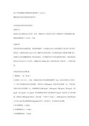
Rotor dimensions (in mm; 1 mm=0.03937 inches)<br />
b 2<br />
c<br />
∅d z<br />
∅d c<br />
∅d zi<br />
b 3 b 3<br />
b 5 b 1 5<br />
b 7 b 4<br />
2<br />
b 6<br />
x s<br />
∅d za<br />
d<br />
∅d F<br />
∅d G<br />
∅d A<br />
A<br />
∅d B<br />
View A<br />
x S =Measuring plane<br />
(Center of the installation)<br />
Plane of temperature<br />
measurement<br />
8xY<br />
Dimensions without tolerances per DIN ISO 2768-mK<br />
∅d B<br />
Measuring range<br />
Dimensions in mm<br />
b 1 b 2 b 3 b 4 b 5 b 6 b 7 c d x S Y<br />
500 N⋅m/1 kN⋅m 22 60 18 4 4 45.7 14 2 8 30 M10<br />
2 kN⋅m/3 kN⋅m 23 64 20 5 4 47.7 14 2.5 8 32 M12<br />
5 kN⋅m 24.8 84 26 3.3 3 62.7 17.5 2.8 8 42 M14<br />
10 kN⋅m 24.8 92 30 3.3 4 66.7 17.5 3.5 10 46 M16<br />
Measuring range<br />
Dimensions in mm<br />
∅d A ∅d B ∅d C ∅d F ∅d G ∅d K ∅d C12 S ∅d Z ∅d za g5 ∅d H6 zi<br />
500 N⋅m/1 kN⋅m 136.5 101.5 120 124 133 17 10 151 75 75<br />
2 kN⋅m/3 kN⋅m 172.5 130 155 160 169 19 12 187 90 90<br />
5 kN⋅m 200.5 155.5 179 188 197 22 14.2 221 110 110<br />
10 kN⋅m 242.5 196 221 230 239 26 17 269 140 140<br />
B1941-4.0 en<br />
7<br />
HBM
Stator dimensions (in mm; 1 mm=0.03937 inches)<br />
min. 43<br />
Reserved additional space for connected<br />
status min. 10 *)<br />
Reserved additional space for mounting<br />
and dismounting approx. j 20<br />
View Z<br />
180<br />
150<br />
M6<br />
Maximum thread reach 10 +1<br />
approx. 100<br />
Reserved additional space for<br />
connection cable with male<br />
connector<br />
Female cable connector in 4 angular<br />
positions adjustable<br />
Accessories female cable connector 7-<br />
alternatively 8-pin 90° cable run<br />
approx. 54<br />
UNF 1/4”<br />
Maximum thread reach 0.4” +0.02”<br />
114.3 = 4 1/2”<br />
*) Min. 14 mm with 5 kN⋅m and 10 kN⋅m<br />
Side view Y<br />
b<br />
Air gap area:<br />
Radial = 10 mm<br />
Axial = b 2 (see page 7)<br />
Side view X<br />
X<br />
24<br />
28<br />
45<br />
66<br />
H2<br />
H1<br />
Y<br />
62<br />
10 8<br />
28 (28)<br />
6.5<br />
56<br />
Stator center<br />
Z<br />
Top view<br />
Dimensions without tolerances per DIN ISO 2768-mK<br />
Only with speed measuring system and<br />
speed measuring system with reference mark<br />
Measuring range<br />
Dimensions in mm<br />
(NVm) b ∅D H1 H2<br />
500<br />
1 k<br />
91.5 143 280 204.5<br />
2 k<br />
3 k<br />
109.5 179 310 222.5<br />
5 k 123.5 207 333 239.5<br />
10 k 144.5 249 369 263.5<br />
HBM 8<br />
B1941-4.0 en
Stator dimensions 500 N⋅m ... 1 kN⋅m with protection against contact (in mm)<br />
(Cover plate)<br />
58 (Protection against contact, complete)<br />
1 1<br />
56<br />
(Protection<br />
against contact)<br />
(Cover plate)<br />
A<br />
∅ 139<br />
1 (58) 1<br />
(56)<br />
12 32<br />
204.5<br />
99.3<br />
98<br />
317<br />
103.5 102.5<br />
∅ 223 +2<br />
∅ 205<br />
∅ 196<br />
∅ 187 −2<br />
View without protection against<br />
contact (half)<br />
Z<br />
Z<br />
Z<br />
∅ 11<br />
Z<br />
90<br />
(Stop screw)<br />
View A<br />
Connection apertures Z<br />
∅ 6.6<br />
40<br />
(56) Protection against contact<br />
∅ 11<br />
98<br />
∅ 6.6<br />
43<br />
Connection aperture with spot face<br />
View without cover plate<br />
B1941-4.0 en<br />
9<br />
HBM
Stator dimensions 2 kN⋅m ... 10 kN⋅m with protection against contact (in mm)<br />
(Protection against contact, compl.)<br />
b 4 b 1 b 5<br />
b<br />
b 3 b 2 b 3 A<br />
2<br />
∅d 1<br />
b 6 b 7<br />
(Cover plate)<br />
(Cover plate)<br />
b 1<br />
b 8<br />
H1<br />
H2<br />
H3<br />
H4 H5<br />
∅d 2<br />
∅d 3<br />
∅d 4<br />
∅d 5<br />
View A<br />
Z<br />
Z<br />
Z<br />
∅11<br />
∅6.6<br />
Z<br />
H6<br />
H7<br />
(Stop screw)<br />
View without protection<br />
against contact (half)<br />
Connection apertures Z<br />
b 2 Protection against contact<br />
(∅11)<br />
b 9<br />
(∅6.6)<br />
Connection aperture with spot face<br />
View without cover plate<br />
Measuring range<br />
Dimensions in mm<br />
b 1 b 2 b 3 b 4 b 5 b 6 b 7 b 8 b 9 H1 H2 H3 H4 H5 H6 H7<br />
2 kN⋅m/3 kN⋅m 58 56 1 2 4 12 32 43 97.5 116 222.5 153 121.5 120.5 107 117.3<br />
5 kN⋅m 80 78 1 2 2 12 32 65 99 133 239.5 384 138.5 134.5 120 134.3<br />
10 kN⋅m 88 86 1 2 2 12 32 73 99 157 263.5 429 162.5 155.5 145 158.3<br />
Measuring range<br />
Dimensions in mm<br />
∅d 1 ∅d 2 ∅d 3 ∅d 4 ∅d 5<br />
2 kN⋅m/3 kN⋅m 175 259 +2 241 232 223 −2<br />
5 kN⋅m 203 289 +2 269 260 249 −2<br />
10 kN⋅m 245 331 +2 311 302 291 −2<br />
HBM 10<br />
B1941-4.0 en
Dimensions cover plates (in mm)<br />
Distance bolt only with<br />
5 kNm and 10 kNm<br />
Screw head<br />
Outside<br />
diameter=7<br />
Height=2<br />
Screw head<br />
(Stop screw)<br />
Outside<br />
diameter=9<br />
Height=2.5<br />
B1941-4.0 en<br />
11<br />
HBM
Bolted connection of the rotor<br />
Rotor<br />
Fastening bolts<br />
Bolt distribution view A<br />
B<br />
A<br />
Hexagon socket head bolts<br />
DIN EN ISO 4762; black/oiled/m tot =0,125<br />
(turned into the plane of projection)<br />
Bolt distribution view B<br />
Nominal (rated)<br />
torque<br />
(NVm)<br />
500<br />
1k<br />
2k<br />
3k<br />
Fastening bolts<br />
Property class of<br />
fastening bolts<br />
Prescribed<br />
tightening moment<br />
(NVm)<br />
M10<br />
10.9<br />
67<br />
M12<br />
115<br />
135<br />
5k M14 12.9<br />
220<br />
10k<br />
M16<br />
340<br />
Mounting dimensions<br />
Center of Rotor<br />
Center of Stator<br />
Measuring<br />
range<br />
500 N⋅m<br />
1 kN⋅m<br />
2 kN⋅m<br />
3 kN⋅m<br />
(Tolerance 1 mm)<br />
Mounting dimensions<br />
Mounting dimensions (mm)<br />
a b c<br />
2 2 0<br />
5 3 1<br />
5 kN⋅m 25 3 11<br />
10 kN⋅m 33 3 15<br />
Reserved additional space for fielbus cable:<br />
approx. 140 mm, from male connector area<br />
B1941-4.0 en<br />
a<br />
c<br />
b<br />
12<br />
HBM
Radial and axial run-out tolerances<br />
Axial run-out AB<br />
B<br />
A<br />
Radial run-out AB<br />
Internal centering<br />
Hardness 46 ... 54 HRC<br />
0.8<br />
Quality of the axial and radial runout<br />
surfaces (A, B and AB)<br />
Measuring range (NVm) Axial run−out tolerance (mm) Radial run−out tolerance (mm)<br />
500 0.01 0.01<br />
1 k 0.01 0.01<br />
2 k 0.02 0.02<br />
3 k 0.02 0.02<br />
5 k 0.025 0.025<br />
10 k 0.025 0.025<br />
HBM 13<br />
B1941-4.0 en
Order numbers<br />
Code<br />
S500Q<br />
S001R<br />
S002R<br />
S003R<br />
S005R<br />
S010R<br />
Code<br />
S<br />
G<br />
<br />
Option 1: Measuring range<br />
500 N⋅m<br />
1 kN⋅m<br />
2 kN⋅m<br />
3 kN⋅m<br />
5 kN⋅m<br />
10 kN⋅m<br />
Option 2: Accuracy<br />
Standard<br />
Higher Accuracy 1)<br />
Lin. 0.01 % and TC 0 0.01 %/10 K<br />
Code<br />
C<br />
P<br />
Option 5: Bus connection<br />
CANopen (2 male device connectors)<br />
CANopen and Profibus DPV1<br />
Code<br />
N<br />
Option 6: Speed measuring system<br />
Without speed measuring system<br />
1 With optical speed measuring system; 360 or 720 pulses/revolution<br />
A<br />
With optical speed measuring system; 360 or 720 pulses/revolution<br />
and reference pulse<br />
Code<br />
L<br />
H<br />
Option 3: Nominal (rated) speed<br />
Depending on measuring range up to 12,000 rpm<br />
Depending on measuring range up to 16,000 rpm<br />
Code<br />
N<br />
Y<br />
Option 7: Protection against contact<br />
Without protection against contact<br />
With protection against contact<br />
Code<br />
DF1<br />
DU2<br />
SF1<br />
SU2<br />
Option 4: Electrical configuration<br />
Output signal 60 kHz 30 kHz<br />
Output signal 60 kHz 30 kHz and 10 V<br />
Output signal 10 kHz 5 kHz<br />
Output signal 10 kHz 5 kHz and 10 V<br />
Code Option 8: MODULFLEX ) coupling 2)<br />
N Without coupling<br />
Y With mounted coupling<br />
Code Option 9: Customer-specific modification<br />
N No customer-specific modification<br />
Order no.:<br />
K-T12 −<br />
Ordering example:<br />
K-T12 − S 5 0 0 Q S L S F 1 C<br />
1<br />
N<br />
N<br />
N<br />
1) With voltage output: Lin. 0.05 %;<br />
TC 0 0.1 %/10 K<br />
2) Only with option 3, Code L; specifications<br />
see <strong>Data</strong> sheet B1958-xx en<br />
B1941-4.0 en<br />
14<br />
HBM
Accessories, to be ordered separately:<br />
Item<br />
Ready made connecting cables<br />
<strong>Torque</strong><br />
Connecting cable torque, Binder 423 7-pole − D-Sub 15-pole, 6 m<br />
Connecting cable torque, Binder 423 − pigtails, 6 m<br />
Rotational speed<br />
Connecting cable rot. speed, Binder 423 8-pole − D-Sub 15-pole, 6 m<br />
Connecting cable rot. speed, Binder 423 8-pole − pigtails, 6 m<br />
Connecting cable rot. speed, reference pulse, Binder 423 8-pole − D-Sub 15-pole, 6 m<br />
Connecting cable rot. speed, reference pulse, Binder 423 8-pole − pigtails, 6 m<br />
CANbus<br />
Connecting cable CANbus, M12 A-encoded − D-Sub 9-pole, connectable termination resistor, 6 m<br />
Male/female cable connectors<br />
<strong>Torque</strong><br />
Order-No.<br />
1−KAB149−6<br />
1−KAB153−6<br />
1−KAB150−6<br />
1−KAB154−6<br />
1−KAB163−6<br />
1−KAB164−6<br />
1−KAB161−6<br />
423G−7S, female cable connector 7-pole, straight cable entry, for torque output (connector 1, connector 3) 3−3101.0247<br />
423W−7S, female cable connector 7-pole, 90° cable entry, for torque output (connector 1, connector 3) 3−3312.0281<br />
Rotational speed<br />
423G−8S, female cable connector 8-pole, straight cable entry, for rot. speed output (connector 2) 3−3312.0120<br />
423W−8S, female cable connector 8-pole, 90° cable entry, for rot. speed output (connector 2) 3−3312.0282<br />
CANbus<br />
TERMINATOR M12/ termination resistor, M12, A-encoded, 5-pole, male connector<br />
Termination resistor CANbus M12, A-encoded, 5-pole, female connector<br />
T-unit M12, A-encoded, 5-pole<br />
Male/female cable connector/CANbus M12, female cable connector 5-pole M12, A-encoded, male cable connector<br />
5-pole M12, A-encoded<br />
PROFIBUS<br />
Connecting cable, Y junction, M12 female, B-encoded; M12 male, B-encoded; M12 female, B-encoded, 2 m<br />
Male/female cable connector/PROFIBUS M12, female cable connector 5-pole M12, B-encoded, male cable connector<br />
5-pole M12, B-encoded<br />
Termination resistor PROFIBUS M12, B-encoded, 5-pole<br />
T-unit PROFIBUS M12, B-encoded, 5-pole<br />
Connecting cable, by the meter<br />
1−CANHEAD−TERM<br />
1−CAN−AB−M12<br />
1−CANHEAD−M12−T<br />
1−CANHEAD−M12<br />
1−KAB167-2<br />
1−PROFI−M12<br />
1−PROFI−AB−M12<br />
1−PROFI−VT−M12<br />
Kab8/00−2/2/2 4−3301.0071<br />
Kab8/00−2/2/2/1/1 4−3301.0183<br />
DeviceNet cable 4−3301.0180<br />
Miscellaneous<br />
Setup-Toolkit for T12 (T12 system CD, PCAN−USB adapter, connecting cable CANbus, 6 m)<br />
1−T12−SETUP−USB<br />
HBM 15<br />
B1941-4.0 en
Modifications reserved.<br />
All details describe our products in general form only. They<br />
are not to be understood as express warranty and do not<br />
constitute any liability whatsoever.<br />
B1941-4.0 en<br />
Hottinger Baldwin Messtechnik GmbH<br />
Im Tiefen See 45, D-64293 Darmstadt, Germany<br />
Tel.: +49 6151 8030; Fax: +49 6151 803 9100<br />
E−mail: support@hbm.com www.hbm.com