466049 - Integra - 90-93 - Radio Install - The Install Doctor
466049 - Integra - 90-93 - Radio Install - The Install Doctor
466049 - Integra - 90-93 - Radio Install - The Install Doctor

Create successful ePaper yourself
Turn your PDF publications into a flip-book with our unique Google optimized e-Paper software.
<strong>Integra</strong> 19<strong>90</strong><br />
Acura<br />
thru 19<strong>93</strong><br />
<strong>Radio</strong> Replacement<br />
Document #: <strong>466049</strong><br />
I<br />
Click on a link<br />
tab to jump to<br />
that page<br />
www.installdr.com<br />
Cover<br />
Page<br />
Before<br />
You Begin<br />
Remove<br />
& <strong>Install</strong><br />
Wire<br />
New <strong>Radio</strong><br />
TM<br />
Mount<br />
New <strong>Radio</strong><br />
Publication, Duplication, or Retransmission Of This Document Not Expressly Authorized In Writing By <strong>The</strong> <strong>Install</strong> <strong>Doctor</strong> Is Prohibited. Protected By U.S. Copyright Laws. © 1997,1998,1999,2000.<br />
Step By Step Wiring<br />
Page 1 of 2<br />
Auto Makers<br />
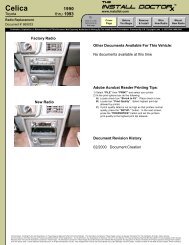
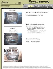
Factory<br />
<strong>Radio</strong><br />
New <strong>Radio</strong><br />
Wire Harness Inside Vehicles<br />
Dash Which Plugs Into <strong>The</strong><br />
Rear Of <strong>The</strong> Factory <strong>Radio</strong><br />
(Note: the radio shown is for display purposes and may not be similar in<br />
size or dimensions than the auto makers factory radio in your vehicle)<br />
Supplemental information if you need help<br />
Document Title Document #<br />
Testing wires when installing a new radio 99<strong>90</strong>13<br />
Why use an OEM snap on wire harness 99<strong>90</strong>08<br />
Wiring your new radio using a wire harness 99<strong>90</strong>09<br />
Wire splicing: soldering vs. crimping 99<strong>90</strong>04<br />
Optional (STRONGLY<br />
RECOMMENDED) Snap On Wire<br />
Harness That Splices Into <strong>The</strong><br />
Wires Of <strong>The</strong> New <strong>Radio</strong><br />
Wiring Instructions:<br />
<strong>The</strong> power and speaker wires needed to connect the new radio are attached to<br />
the connector of the wire harness located inside the vehicles dash. <strong>The</strong> <strong>Install</strong><br />
<strong>Doctor</strong> STRONGLY recommends using an optional snap on wire harness that is<br />
specifically designed to snap into the vehicles dash wire harness connector.<br />
This will keep you from cutting the vehicles wires. This optional snap on wire<br />
harness will have wires on the opposite side of the connector that will allow you<br />
to splice these wires to the new radios wires. <strong>The</strong> only other option is to cut off<br />
the vehicles dash wire harness connector and splice the new radios wires<br />
directly to these wires. <strong>The</strong> optional snap on wire harness takes all the guess<br />
work out of trying to figure out what each wire is in the vehicles dash wire<br />
harness. <strong>The</strong> optional snap on wire harness shows you what each wire is.<br />
Ground Wire<br />
STEP 1<br />
Connect the GROUND wire of the new radio to the ground wire of a<br />
snap on wire harness OR crimp a ring terminal connector to this wire<br />
and screw the ring terminal to metal inside the vehicles dash.<br />
Ground Wire<br />
POWER AND SPEAKER WIRES FROM NEW RADIO<br />
+12 Volt<br />
Battery Wire<br />
+12 Volt<br />
Ignition Wire<br />
Power Antenna<br />
Wire (if available)<br />
Left Front Speaker Wires<br />
Right Front Speaker Wires<br />
Left Rear<br />
Speaker Wires<br />
Right Rear Speaker Wires<br />
STEP 2<br />
Connect the +12 Volt Battery or Constant wire of the new radio to<br />
either the +12 Volt Battery wire of a snap on wire harness OR connect<br />
this wire to the +12 Volt Battery wire found in the wire chart above.<br />
STEP 3<br />
Connect the +12 Volt Ignition or Switch wire of the new radio to<br />
either the +12 Volt Ignition wire of a snap on wire harness OR connect<br />
this wire to the +12 Volt Ignition wire found in the wire chart above.<br />
STEP 4<br />
If your vehicle has a POWER ANTENNA connect the<br />
POWER ANTENNA wire of the new radio to either the POWER<br />
ANTENNA wire on a snap on wire harness OR wire in chart above.<br />
STEP 5<br />
Connect the LEFT FRONT speaker wires from the new radio to the<br />
LEFT FRONT speaker wires on a snap on wire harness OR the<br />
LEFT FRONT speaker wires found in the chart above.<br />
STEP 6<br />
Connect the RIGHT FRONT speaker wires from the new radio to the<br />
RIGHT FRONT speaker wires on a snap on wire harness OR the<br />
RIGHT FRONT speaker wires found in the chart above.<br />
STEP 7<br />
Connect the LEFT REAR speaker wires from the new radio to the<br />
LEFT REAR speaker wires on a snap on wire harness OR the<br />
LEFT REAR speaker wires found in the chart above.<br />
STEP 8<br />
Connect the RIGHT REAR speaker wires from the new radio to the<br />
RIGHT REAR speaker wires on a snap on wire harness OR the<br />
RIGHT REAR speaker wires found in the chart above.<br />
+12 Volt<br />
Battery Wire<br />
+12 Volt<br />
Ignition Wire<br />
Power Antenna<br />
Wire (if available)<br />
Left Front Speaker Wires<br />
Right Front Speaker Wires<br />
Left Rear<br />
Speaker Wires<br />
Right Rear Speaker Wires<br />
POWER AND SPEAKER WIRES FROM THE VEHICLES<br />
DASH WIRE HARNESS OR SNAP ON WIRE HARNESS<br />
All Information, Including Photos And Illustrations, In <strong>The</strong>se Pages Is Believed To Be Correct And Reliable. <strong>The</strong> Information Contained In <strong>The</strong>se Pages Is Given As General Information For <strong>The</strong> <strong>Install</strong>ation Of Audio, Video, Security,<br />
Communications, And Other Accessory Products Into Mobile And/Or Vehicle Applications. <strong>The</strong> <strong>Install</strong> <strong>Doctor</strong>, Any Subsidiaries Or Divisions <strong>The</strong>reof, Or Any Member Of <strong>The</strong>se Companies Shall Not Be Held Liable For Any Damages And/Or Injuries<br />
Resulting From <strong>The</strong> Use Of Information Contained In <strong>The</strong>se Pages. All Information Contained In <strong>The</strong>se Pages Should Be Checked And Verified With Appropriate Test Equipment To Assure <strong>The</strong> Safety And Proper Operation Of Equipment <strong>Install</strong>ed<br />
And <strong>The</strong> Vehicle Itself. Careful Attention Should Be Given To All Electronic/Electric Circuits. High Voltages And Currents Can Cause Bodily Injury, Skin Damage, And Even Death. <strong>Install</strong>s Are Taken At <strong>The</strong> Risk Of Each <strong>Install</strong>er, And/Or Individual.