Directly In Acrobat Reader - The Install Doctor
Directly In Acrobat Reader - The Install Doctor
Directly In Acrobat Reader - The Install Doctor

You also want an ePaper? Increase the reach of your titles
YUMPU automatically turns print PDFs into web optimized ePapers that Google loves.
Corolla<br />
Toyota<br />
Radio Replacement<br />
Document #: 869001<br />
1999<br />
I<br />
Click on a link<br />
tab to jump to<br />
that page<br />
www.installdr.com<br />
Cover<br />
Page<br />
Before<br />
You Begin<br />
Remove<br />
& <strong>In</strong>stall<br />
Wire<br />
New Radio<br />
TM<br />
Mount<br />
New Radio<br />
Publication, Duplication, or Retransmission Of This Document Not Expressly Authorized <strong>In</strong> Writing By <strong>The</strong> <strong>In</strong>stall <strong>Doctor</strong> Is Prohibited. Protected By U.S. Copyright Laws. © 1997,1998,1999,2000.<br />
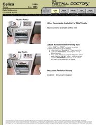
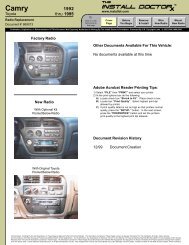
Factory Radio<br />
Other Documents Available For This Vehicle:<br />
No documents available at this time<br />
Adobe <strong>Acrobat</strong> <strong>Reader</strong> Printing Tips:<br />
New Radio<br />
1) Select “FILE” then “PRINT” and select your printer.<br />
2) <strong>In</strong> the print options box do the following:<br />
A) Locate check box “Shrink to Fit”. Place check in box.<br />
B) Locate box “Print Quality”. Select highest print dpi<br />
allowed by printer.<br />
C) If print quality listed is not as high as that printers normal<br />
quality, press the “SETUP..” button. <strong>In</strong> the next screen,<br />
press the “PROPERTIES” button and set the printers<br />
print quality to the highest print dpi allowed.<br />
Document Revision History<br />
09/99 Document Creation<br />
All <strong>In</strong>formation, <strong>In</strong>cluding Photos And Illustrations, <strong>In</strong> <strong>The</strong>se Pages Is Believed To Be Correct And Reliable. <strong>The</strong> <strong>In</strong>formation Contained <strong>In</strong> <strong>The</strong>se Pages Is Given As General <strong>In</strong>formation For <strong>The</strong> <strong>In</strong>stallation Of Audio, Video, Security,<br />
Communications, And Other Accessory Products <strong>In</strong>to Mobile And/Or Vehicle Applications. <strong>The</strong> <strong>In</strong>stall <strong>Doctor</strong>, Any Subsidiaries Or Divisions <strong>The</strong>reof, Or Any Member Of <strong>The</strong>se Companies Shall Not Be Held Liable For Any Damages And/Or <strong>In</strong>juries<br />
Resulting From <strong>The</strong> Use Of <strong>In</strong>formation Contained <strong>In</strong> <strong>The</strong>se Pages. All <strong>In</strong>formation Contained <strong>In</strong> <strong>The</strong>se Pages Should Be Checked And Verified With Appropriate Test Equipment To Assure <strong>The</strong> Safety And Proper Operation Of Equipment <strong>In</strong>stalled<br />
And <strong>The</strong> Vehicle Itself. Careful Attention Should Be Given To All Electronic/Electric Circuits. High Voltages And Currents Can Cause Bodily <strong>In</strong>jury, Skin Damage, And Even Death. <strong>In</strong>stalls Are Taken At <strong>The</strong> Risk Of Each <strong>In</strong>staller, And/Or <strong>In</strong>dividual.
Corolla<br />
Toyota<br />
Radio Replacement<br />
Document #: 869001<br />
1999<br />
I<br />
Click on a link<br />
tab to jump to<br />
that page<br />
www.installdr.com<br />
Cover<br />
Page<br />
Before<br />
You Begin<br />
Remove<br />
& <strong>In</strong>stall<br />
Wire<br />
New Radio<br />
TM<br />
Mount<br />
New Radio<br />
Publication, Duplication, or Retransmission Of This Document Not Expressly Authorized <strong>In</strong> Writing By <strong>The</strong> <strong>In</strong>stall <strong>Doctor</strong> Is Prohibited. Protected By U.S. Copyright Laws. © 1997,1998,1999,2000.<br />
Overview Of This Radio <strong>In</strong>stall<br />
Parts Needed For This Radio <strong>In</strong>stall<br />
Step<br />
Remove old radio from dash<br />
What Section To Go To<br />
Remove & <strong>In</strong>stall<br />
Parts REQUIRED for the install<br />
Snap on wire harness<br />
Description<br />
1989 and newer Toyota<br />
Wire the new radio<br />
Wire New Radio<br />
Mount the new radio<br />
Mount New Radio<br />
Finishing the installation<br />
Remove & <strong>In</strong>stall<br />
Optional parts for this install<br />
None<br />
Tools Needed To Complete This <strong>In</strong>stall<br />
TOOL TIPS:<br />
#2<br />
Phillips<br />
Flat<br />
Head<br />
Hand tools needed<br />
to remove radio<br />
Solder/<br />
Crimper<br />
Voltage<br />
Meter<br />
Small<br />
Battery<br />
Accessory tools needed to test and<br />
wire the new radio<br />
PLUS: Wire ties or electrical tape: to neatly bundle and organize your<br />
wires for a professional appearance.<br />
Small Battery: use a battery to test speaker wires. Touching the (+) positive<br />
and (-) negative baterry leads to a pair of speaker will cause the speaker to<br />
make a “Pop” sound indicating that pair of wires goes to that speaker.<br />
Voltage Meter: Always check +12 Volt power wires for voltage before<br />
making wire connections. <strong>The</strong>se wires will fluctuate between 10 and 14 Volts.<br />
Solder Iron or Crimp Tool: make wire to wire connections using either a<br />
solder iron and electrical tape, OR plastic crimp terminals found at most<br />
hardware or auto parts stores.<br />
<strong>In</strong>stallation Difficulty Ratings<br />
Easy. No advanced skills or specialty tools needed.<br />
Basics. Simple tools required. <strong>In</strong>stalls quickly.<br />
<strong>In</strong>termediate. Requires knowledge of tools, or disassembly of panels.<br />
Advanced. Requires advanced tools, or extra time.<br />
Difficult. <strong>In</strong>volves modifying or cutting of the installation area. Advanced<br />
tools and/or skills required. Best if performed by experienced installers.<br />
Do It Yourselfers<br />
Basics<br />
Professional <strong>In</strong>staller<br />
Basics<br />
Support <strong>In</strong>formation If You Need Help<br />
Supplemental information if you need help<br />
Document Title Document #<br />
Basic DC electronics for automotive applications 999001<br />
Wire splicing: soldering vs. crimping 999004<br />
Why use radio installation kits 999005<br />
Mounting your radio to an installation kit 999007<br />
Why use an optional snap on wire harness 999008<br />
Wiring your new radio using a wire harness 999009<br />
Testing wires when installing a new radio 999013<br />
All <strong>In</strong>formation, <strong>In</strong>cluding Photos And Illustrations, <strong>In</strong> <strong>The</strong>se Pages Is Believed To Be Correct And Reliable. <strong>The</strong> <strong>In</strong>formation Contained <strong>In</strong> <strong>The</strong>se Pages Is Given As General <strong>In</strong>formation For <strong>The</strong> <strong>In</strong>stallation Of Audio, Video, Security,<br />
Communications, And Other Accessory Products <strong>In</strong>to Mobile And/Or Vehicle Applications. <strong>The</strong> <strong>In</strong>stall <strong>Doctor</strong>, Any Subsidiaries Or Divisions <strong>The</strong>reof, Or Any Member Of <strong>The</strong>se Companies Shall Not Be Held Liable For Any Damages And/Or <strong>In</strong>juries<br />
Resulting From <strong>The</strong> Use Of <strong>In</strong>formation Contained <strong>In</strong> <strong>The</strong>se Pages. All <strong>In</strong>formation Contained <strong>In</strong> <strong>The</strong>se Pages Should Be Checked And Verified With Appropriate Test Equipment To Assure <strong>The</strong> Safety And Proper Operation Of Equipment <strong>In</strong>stalled<br />
And <strong>The</strong> Vehicle Itself. Careful Attention Should Be Given To All Electronic/Electric Circuits. High Voltages And Currents Can Cause Bodily <strong>In</strong>jury, Skin Damage, And Even Death. <strong>In</strong>stalls Are Taken At <strong>The</strong> Risk Of Each <strong>In</strong>staller, And/Or <strong>In</strong>dividual.
Corolla<br />
Toyota<br />
Radio Replacement<br />
Document #: 869001<br />
1999<br />
I<br />
Click on a link<br />
tab to jump to<br />
that page<br />
www.installdr.com<br />
Cover<br />
Page<br />
Before<br />
You Begin<br />
Remove<br />
& <strong>In</strong>stall<br />
Wire<br />
New Radio<br />
TM<br />
Mount<br />
New Radio<br />
Publication, Duplication, or Retransmission Of This Document Not Expressly Authorized <strong>In</strong> Writing By <strong>The</strong> <strong>In</strong>stall <strong>Doctor</strong> Is Prohibited. Protected By U.S. Copyright Laws. © 1997,1998,1999,2000.<br />
Remove Factory Radio<br />
STEP 1:<br />
<strong>The</strong> radio is secured to the frame of the<br />
vehicles dash with screws located behind the<br />
plastic dash panel surrounding the radio.<br />
This plastic dash panel unsnaps from the<br />
body of the vehicles dash.<br />
STEP 2:<br />
<strong>The</strong> bottom of the plastic dash panel, just<br />
below the bottom of the radio, can be lifted<br />
up. Look up from the below the radio and<br />
you will notice rectangular openings or<br />
insertion points where a flat tool can be<br />
inserted to pry out the bottom of the plastic<br />
dash panel. With a flat head screwdriver or<br />
other flat object, pry out the bottom of the<br />
plastic dash panel<br />
STEP 3:<br />
Once the bottom edge of the plastic dash<br />
panel has been pulled out, the sides of the<br />
plastic dash panel will begin to separate from<br />
the body of the vehicles dash. You will now<br />
be able to put your fingers into the openings<br />
on the sides of the plastic dash panel.<br />
Gently pull the plastic dash panel until it<br />
unsnaps from the body of the vehicles dash.<br />
STEP 4:<br />
STEP 5:<br />
Once all the clips on the plastic dash panel<br />
have been unsnapped, the dash can be<br />
pulled out. <strong>The</strong> top of the plastic dash panel<br />
will have wires attached to the clock, hazard<br />
and defrost switches. You do NOT need to<br />
unplug the connectors plugged into them.<br />
Move the plastic dash panel up and set it on<br />
top of the body of the dash.<br />
<strong>The</strong> radio is held in with four (4) phillips screws /<br />
8 mm bolts. Remove the screw/bolts. Pull the<br />
radio forward.<br />
Unplug the antenna cable, and 2 white connectors<br />
from the rear of the radio.<br />
Wiring <strong>The</strong> New Radio<br />
Move to: Wire New Radio Section<br />
Mounting <strong>The</strong> Radio Options<br />
Move to: Mounting New Radio Section<br />
<strong>The</strong> <strong>In</strong>stall <strong>Doctor</strong> STRONGLY recommends purchasing a<br />
‘DIN’ radio for this vehicle. ‘DIN’ radios are a direct<br />
replacement for the Toyota radio in this vehicle. More<br />
information is available in the Mounting New Radio section.<br />
All <strong>In</strong>formation, <strong>In</strong>cluding Photos And Illustrations, <strong>In</strong> <strong>The</strong>se Pages Is Believed To Be Correct And Reliable. <strong>The</strong> <strong>In</strong>formation Contained <strong>In</strong> <strong>The</strong>se Pages Is Given As General <strong>In</strong>formation For <strong>The</strong> <strong>In</strong>stallation Of Audio, Video, Security,<br />
Communications, And Other Accessory Products <strong>In</strong>to Mobile And/Or Vehicle Applications. <strong>The</strong> <strong>In</strong>stall <strong>Doctor</strong>, Any Subsidiaries Or Divisions <strong>The</strong>reof, Or Any Member Of <strong>The</strong>se Companies Shall Not Be Held Liable For Any Damages And/Or <strong>In</strong>juries<br />
Resulting From <strong>The</strong> Use Of <strong>In</strong>formation Contained <strong>In</strong> <strong>The</strong>se Pages. All <strong>In</strong>formation Contained <strong>In</strong> <strong>The</strong>se Pages Should Be Checked And Verified With Appropriate Test Equipment To Assure <strong>The</strong> Safety And Proper Operation Of Equipment <strong>In</strong>stalled<br />
And <strong>The</strong> Vehicle Itself. Careful Attention Should Be Given To All Electronic/Electric Circuits. High Voltages And Currents Can Cause Bodily <strong>In</strong>jury, Skin Damage, And Even Death. <strong>In</strong>stalls Are Taken At <strong>The</strong> Risk Of Each <strong>In</strong>staller, And/Or <strong>In</strong>dividual.
Corolla<br />
Toyota<br />
Radio Replacement<br />
Document #: 869001<br />
1999<br />
I<br />
Click on a link<br />
tab to jump to<br />
that page<br />
www.installdr.com<br />
Cover<br />
Page<br />
Before<br />
You Begin<br />
Remove<br />
& <strong>In</strong>stall<br />
Wire<br />
New Radio<br />
TM<br />
Mount<br />
New Radio<br />
Publication, Duplication, or Retransmission Of This Document Not Expressly Authorized <strong>In</strong> Writing By <strong>The</strong> <strong>In</strong>stall <strong>Doctor</strong> Is Prohibited. Protected By U.S. Copyright Laws. © 1997,1998,1999,2000.<br />
Completing <strong>The</strong> Radio <strong>In</strong>stallation<br />
STEP 1:<br />
Plug the antenna cable into the rear of the<br />
new radio. Make sure all wiring to the new<br />
radio has been completed and connect any<br />
connectors into the rear of the new radio.<br />
<strong>In</strong>sert the new radio into the dash opening<br />
and align the metal brackets to their<br />
mounting locations. Secure the radio with<br />
the same 4 phillips screws / 8mm bolts that<br />
had originally secured the auto makers<br />
factory radio.<br />
STEP 2:<br />
Reattach the plastic dash panel onto the body<br />
of the vehicles dash.<br />
<strong>The</strong> radio installation is now complete.<br />
All <strong>In</strong>formation, <strong>In</strong>cluding Photos And Illustrations, <strong>In</strong> <strong>The</strong>se Pages Is Believed To Be Correct And Reliable. <strong>The</strong> <strong>In</strong>formation Contained <strong>In</strong> <strong>The</strong>se Pages Is Given As General <strong>In</strong>formation For <strong>The</strong> <strong>In</strong>stallation Of Audio, Video, Security,<br />
Communications, And Other Accessory Products <strong>In</strong>to Mobile And/Or Vehicle Applications. <strong>The</strong> <strong>In</strong>stall <strong>Doctor</strong>, Any Subsidiaries Or Divisions <strong>The</strong>reof, Or Any Member Of <strong>The</strong>se Companies Shall Not Be Held Liable For Any Damages And/Or <strong>In</strong>juries<br />
Resulting From <strong>The</strong> Use Of <strong>In</strong>formation Contained <strong>In</strong> <strong>The</strong>se Pages. All <strong>In</strong>formation Contained <strong>In</strong> <strong>The</strong>se Pages Should Be Checked And Verified With Appropriate Test Equipment To Assure <strong>The</strong> Safety And Proper Operation Of Equipment <strong>In</strong>stalled<br />
And <strong>The</strong> Vehicle Itself. Careful Attention Should Be Given To All Electronic/Electric Circuits. High Voltages And Currents Can Cause Bodily <strong>In</strong>jury, Skin Damage, And Even Death. <strong>In</strong>stalls Are Taken At <strong>The</strong> Risk Of Each <strong>In</strong>staller, And/Or <strong>In</strong>dividual.
Corolla<br />
Toyota<br />
Radio Replacement<br />
Document #: 869001<br />
1999<br />
I<br />
Click on a link<br />
tab to jump to<br />
that page<br />
www.installdr.com<br />
Cover<br />
Page<br />
Before<br />
You Begin<br />
Remove<br />
& <strong>In</strong>stall<br />
Wire<br />
New Radio<br />
TM<br />
Mount<br />
New Radio<br />
Publication, Duplication, or Retransmission Of This Document Not Expressly Authorized <strong>In</strong> Writing By <strong>The</strong> <strong>In</strong>stall <strong>Doctor</strong> Is Prohibited. Protected By U.S. Copyright Laws. © 1997,1998,1999,2000.<br />
Step By Step Wiring<br />
Page 1 of 2<br />
Auto Makers<br />
Factory<br />
Radio<br />
New Radio<br />
Wire Harness <strong>In</strong>side Vehicles<br />
Dash Which Plugs <strong>In</strong>to <strong>The</strong><br />
Rear Of <strong>The</strong> Factory Radio<br />
(Note: the radio shown is for display purposes and may not be similar in<br />
size or dimensions than the auto makers factory radio in your vehicle)<br />
Supplemental information if you need help<br />
Document Title Document #<br />
Testing wires when installing a new radio 999013<br />
Why use an OEM snap on wire harness 999008<br />
Wiring your new radio using a wire harness 999009<br />
Wire splicing: soldering vs. crimping 999004<br />
Optional (STRONGLY<br />
RECOMMENDED) Snap On Wire<br />
Harness That Splices <strong>In</strong>to <strong>The</strong><br />
Wires Of <strong>The</strong> New Radio<br />
Wiring <strong>In</strong>structions:<br />
<strong>The</strong> power and speaker wires needed to connect the new radio are attached to<br />
the connector of the wire harness located inside the vehicles dash. <strong>The</strong> <strong>In</strong>stall<br />
<strong>Doctor</strong> STRONGLY recommends using an optional snap on wire harness that is<br />
specifically designed to snap into the vehicles dash wire harness connector.<br />
This will keep you from cutting the vehicles wires. This optional snap on wire<br />
harness will have wires on the opposite side of the connector that will allow you<br />
to splice these wires to the new radios wires. <strong>The</strong> only other option is to cut off<br />
the vehicles dash wire harness connector and splice the new radios wires<br />
directly to these wires. <strong>The</strong> optional snap on wire harness takes all the guess<br />
work out of trying to figure out what each wire is in the vehicles dash wire<br />
harness. <strong>The</strong> optional snap on wire harness shows you what each wire is.<br />
Ground Wire<br />
STEP 1<br />
Connect the GROUND wire of the new radio to the ground wire of a<br />
snap on wire harness OR crimp a ring terminal connector to this wire<br />
and screw the ring terminal to metal inside the vehicles dash.<br />
Ground Wire<br />
POWER AND SPEAKER WIRES FROM NEW RADIO<br />
+12 Volt<br />
Battery Wire<br />
+12 Volt<br />
Ignition Wire<br />
Power Antenna<br />
Wire (if available)<br />
Left Front Speaker Wires<br />
Right Front Speaker Wires<br />
Left Rear<br />
Speaker Wires<br />
Right Rear Speaker Wires<br />
STEP 2<br />
Connect the +12 Volt Battery or Constant wire of the new radio to<br />
either the +12 Volt Battery wire of a snap on wire harness OR connect<br />
this wire to the +12 Volt Battery wire found in the wire chart above.<br />
STEP 3<br />
Connect the +12 Volt Ignition or Switch wire of the new radio to<br />
either the +12 Volt Ignition wire of a snap on wire harness OR connect<br />
this wire to the +12 Volt Ignition wire found in the wire chart above.<br />
STEP 4<br />
If your vehicle has a POWER ANTENNA connect the<br />
POWER ANTENNA wire of the new radio to either the POWER<br />
ANTENNA wire on a snap on wire harness OR wire in chart above.<br />
STEP 5<br />
Connect the LEFT FRONT speaker wires from the new radio to the<br />
LEFT FRONT speaker wires on a snap on wire harness OR the<br />
LEFT FRONT speaker wires found in the chart above.<br />
STEP 6<br />
Connect the RIGHT FRONT speaker wires from the new radio to the<br />
RIGHT FRONT speaker wires on a snap on wire harness OR the<br />
RIGHT FRONT speaker wires found in the chart above.<br />
STEP 7<br />
Connect the LEFT REAR speaker wires from the new radio to the<br />
LEFT REAR speaker wires on a snap on wire harness OR the<br />
LEFT REAR speaker wires found in the chart above.<br />
STEP 8<br />
Connect the RIGHT REAR speaker wires from the new radio to the<br />
RIGHT REAR speaker wires on a snap on wire harness OR the<br />
RIGHT REAR speaker wires found in the chart above.<br />
+12 Volt<br />
Battery Wire<br />
+12 Volt<br />
Ignition Wire<br />
Power Antenna<br />
Wire (if available)<br />
Left Front Speaker Wires<br />
Right Front Speaker Wires<br />
Left Rear<br />
Speaker Wires<br />
Right Rear Speaker Wires<br />
POWER AND SPEAKER WIRES FROM THE VEHICLES<br />
DASH WIRE HARNESS OR SNAP ON WIRE HARNESS<br />
All <strong>In</strong>formation, <strong>In</strong>cluding Photos And Illustrations, <strong>In</strong> <strong>The</strong>se Pages Is Believed To Be Correct And Reliable. <strong>The</strong> <strong>In</strong>formation Contained <strong>In</strong> <strong>The</strong>se Pages Is Given As General <strong>In</strong>formation For <strong>The</strong> <strong>In</strong>stallation Of Audio, Video, Security,<br />
Communications, And Other Accessory Products <strong>In</strong>to Mobile And/Or Vehicle Applications. <strong>The</strong> <strong>In</strong>stall <strong>Doctor</strong>, Any Subsidiaries Or Divisions <strong>The</strong>reof, Or Any Member Of <strong>The</strong>se Companies Shall Not Be Held Liable For Any Damages And/Or <strong>In</strong>juries<br />
Resulting From <strong>The</strong> Use Of <strong>In</strong>formation Contained <strong>In</strong> <strong>The</strong>se Pages. All <strong>In</strong>formation Contained <strong>In</strong> <strong>The</strong>se Pages Should Be Checked And Verified With Appropriate Test Equipment To Assure <strong>The</strong> Safety And Proper Operation Of Equipment <strong>In</strong>stalled<br />
And <strong>The</strong> Vehicle Itself. Careful Attention Should Be Given To All Electronic/Electric Circuits. High Voltages And Currents Can Cause Bodily <strong>In</strong>jury, Skin Damage, And Even Death. <strong>In</strong>stalls Are Taken At <strong>The</strong> Risk Of Each <strong>In</strong>staller, And/Or <strong>In</strong>dividual.
Corolla<br />
Toyota<br />
Radio Replacement<br />
Document #: 869001<br />
1999<br />
I<br />
Click on a link<br />
tab to jump to<br />
that page<br />
www.installdr.com<br />
Cover<br />
Page<br />
Before<br />
You Begin<br />
Remove<br />
& <strong>In</strong>stall<br />
Wire<br />
New Radio<br />
TM<br />
Mount<br />
New Radio<br />
Publication, Duplication, or Retransmission Of This Document Not Expressly Authorized <strong>In</strong> Writing By <strong>The</strong> <strong>In</strong>stall <strong>Doctor</strong> Is Prohibited. Protected By U.S. Copyright Laws. © 1997,1998,1999,2000.<br />
Radio Wire & Color Code <strong>In</strong>formation<br />
Page 2 of 2<br />
Factory in-dash wire harness (this vehicle has a 2 pc harness)<br />
that snaps into the factory radio<br />
A B<br />
C D<br />
K<br />
L<br />
E F G H I J<br />
M N O P<br />
AS VIEWED FROM MATING END OF CONNECTOR<br />
Typical Toyota<br />
Typical New Radio<br />
Pin What It Is <strong>In</strong> Dash Wire Color Equivalent Wire Color<br />
A Right Front Speaker (+) Green Gray<br />
B Left Front Speaker (+) Pink White<br />
C +12 Volt Ignition Wire Gray Red<br />
D +12 Volt Battery Wire Blue w/ Yellow Stripe Yellow<br />
E Right Front Speaker (-) Blue Gray w/ Black Stripe<br />
F Left Front Speaker (-) Purple White w/ Black Stripe<br />
G Ground Wire Black Black<br />
H Power Antenna Wire 1 Blue (join wires 1 & 2<br />
I Power Antenna Wire 2 together to this blue wire)<br />
J<br />
Do Not Use<br />
K Right Rear Speaker (+) Red Purple<br />
L Left Rear Speaker (+) Black Green<br />
M Right Rear Speaker (-) White Purple w/ Black Stripe<br />
N<br />
Do Not Use<br />
O<br />
Do Not Use<br />
P Left Rear Speaker (-) Yellow Green w/ Black Stripe<br />
Note: using an optional snap on wire harness adapter will simplify the wiring. Most snap on<br />
wire harness adapters have already converted and color coded the wires from the auto<br />
makers in dash wire harness to match typical aftermarket radio wire colors.<br />
** <strong>The</strong> wire colors listed in the chart above are typical for this vehicle manufacturer during<br />
these years but may not be the exact colors for this vehicle. This is another reason to use a<br />
snap on wire harness adapter. **<br />
All <strong>In</strong>formation, <strong>In</strong>cluding Photos And Illustrations, <strong>In</strong> <strong>The</strong>se Pages Is Believed To Be Correct And Reliable. <strong>The</strong> <strong>In</strong>formation Contained <strong>In</strong> <strong>The</strong>se Pages Is Given As General <strong>In</strong>formation For <strong>The</strong> <strong>In</strong>stallation Of Audio, Video, Security,<br />
Communications, And Other Accessory Products <strong>In</strong>to Mobile And/Or Vehicle Applications. <strong>The</strong> <strong>In</strong>stall <strong>Doctor</strong>, Any Subsidiaries Or Divisions <strong>The</strong>reof, Or Any Member Of <strong>The</strong>se Companies Shall Not Be Held Liable For Any Damages And/Or <strong>In</strong>juries<br />
Resulting From <strong>The</strong> Use Of <strong>In</strong>formation Contained <strong>In</strong> <strong>The</strong>se Pages. All <strong>In</strong>formation Contained <strong>In</strong> <strong>The</strong>se Pages Should Be Checked And Verified With Appropriate Test Equipment To Assure <strong>The</strong> Safety And Proper Operation Of Equipment <strong>In</strong>stalled<br />
And <strong>The</strong> Vehicle Itself. Careful Attention Should Be Given To All Electronic/Electric Circuits. High Voltages And Currents Can Cause Bodily <strong>In</strong>jury, Skin Damage, And Even Death. <strong>In</strong>stalls Are Taken At <strong>The</strong> Risk Of Each <strong>In</strong>staller, And/Or <strong>In</strong>dividual.
Corolla<br />
Toyota<br />
Radio Replacement<br />
Document #: 869001<br />
1999<br />
I<br />
Click on a link<br />
tab to jump to<br />
that page<br />
www.installdr.com<br />
Cover<br />
Page<br />
Before<br />
You Begin<br />
Remove<br />
& <strong>In</strong>stall<br />
Wire<br />
New Radio<br />
TM<br />
Mount<br />
New Radio<br />
Publication, Duplication, or Retransmission Of This Document Not Expressly Authorized <strong>In</strong> Writing By <strong>The</strong> <strong>In</strong>stall <strong>Doctor</strong> Is Prohibited. Protected By U.S. Copyright Laws. © 1997,1998,1999,2000.<br />
NOTE:<br />
Before you begin: <strong>The</strong> best method to mount a new radio in this vehicle is to<br />
unscrew the auto makers factory radio from the brackets attached to the radio<br />
and screw the new radio into these brackets just as the factory radio was. This<br />
keeps the vehicle looking as stock from the factory as possible and means that<br />
you do not have to purchase an installation kit to mount the radio.<br />
This method is called “ISO” mounting a radio. “ISO” mounting a radio has become a very<br />
common installation method for mounting new replacement radios. <strong>In</strong> order to “ISO” mount<br />
your radio, three things must exist:<br />
1) <strong>The</strong> radio must be a ‘DIN’ style rectangular radio<br />
2) <strong>The</strong> ‘DIN’ radio must have mounting holes predrilled into both sides of the radio to<br />
allow the radio to be secured with screws to the brackets originally attached to the<br />
factory radio.<br />
3) <strong>The</strong> radio must have a removable trim ring surrounding the face of the radio<br />
All information needed to complete an ‘ISO’ mounting of the new<br />
radio to the brackets originally attached to the factory radio is<br />
included on this page. If you are installing a “shafted” style radio<br />
or you will be using an installation kit to mount your new radio<br />
instead of the ‘ISO’ mounting method, you can find additional<br />
help in the following tech documents:<br />
Document Title Document #<br />
Why use radio installation kits 999005<br />
Mounting your radio to an installation kit 999007<br />
Radio security 999010<br />
1<br />
Remove the auto makers factory radio from the vehicle. Remove the screws/bolts securing the<br />
radio to the brackets.<br />
Auto makers original radio with<br />
metal brackets attached to the radio<br />
Removal Tip: some auto makers use phillips screws, some use 8 mm bolts with phillips screw cutouts in the top<br />
of the bolts. For best results use a socket to prevent stripping out the screws. If your radio has hard to remove<br />
phillips screws, insert the tip of the phillips screwdriver into each phillips screw and firmly tap with a hammer to loosen the<br />
tension bond between the phillips screws and the metal chassis of the auto makers factory radio. <strong>The</strong>n attempt to<br />
unscrew the phillips screws.<br />
2<br />
Remove the auto makers factory radio, but leave the brackets.<br />
Tip: Before removing the brackets, carefully look at where the brackets attach to the radio.<br />
<strong>The</strong> brackets will attach to the new radio in exactly the same location and orientation.<br />
3<br />
New radio<br />
On the side of the new ‘DIN’ radio should be predrilled holes to allow you to screw the new<br />
radio into the brackets. Most car radio manufacturers design their radios with many holes on<br />
the side of the radio so the radio can be mounted to many different kinds of bracket<br />
configurations.<br />
New radios removable trim ring surround<br />
the face of the radio<br />
If you are going to mount your radio in this manner, you will probably have to remove the<br />
radios face trim ring around the face of the new radio. This trim ring will most likely prevent<br />
the vehicles dash panel from securing properly back onto the dash.<br />
4<br />
New radio attached to the brackets<br />
originally attached to the factory radio<br />
A common mistake when mounting your new radio to the auto makers radio brackets<br />
is selecting the wrong holes on the side of the new radio.<br />
As stated above, the brackets should attach to the new radio in the exact same spot on<br />
the new radio. If you have problems aligning the brackets to the new radio, reattach<br />
the brackets back onto the auto makers factory radio to see where and how the<br />
brackets attach to that radio, then transfer that bracket to the new radio and the holes<br />
on the side of the new radio.<br />
All <strong>In</strong>formation, <strong>In</strong>cluding Photos And Illustrations, <strong>In</strong> <strong>The</strong>se Pages Is Believed To Be Correct And Reliable. <strong>The</strong> <strong>In</strong>formation Contained <strong>In</strong> <strong>The</strong>se Pages Is Given As General <strong>In</strong>formation For <strong>The</strong> <strong>In</strong>stallation Of Audio, Video, Security,<br />
Communications, And Other Accessory Products <strong>In</strong>to Mobile And/Or Vehicle Applications. <strong>The</strong> <strong>In</strong>stall <strong>Doctor</strong>, Any Subsidiaries Or Divisions <strong>The</strong>reof, Or Any Member Of <strong>The</strong>se Companies Shall Not Be Held Liable For Any Damages And/Or <strong>In</strong>juries<br />
Resulting From <strong>The</strong> Use Of <strong>In</strong>formation Contained <strong>In</strong> <strong>The</strong>se Pages. All <strong>In</strong>formation Contained <strong>In</strong> <strong>The</strong>se Pages Should Be Checked And Verified With Appropriate Test Equipment To Assure <strong>The</strong> Safety And Proper Operation Of Equipment <strong>In</strong>stalled<br />
And <strong>The</strong> Vehicle Itself. Careful Attention Should Be Given To All Electronic/Electric Circuits. High Voltages And Currents Can Cause Bodily <strong>In</strong>jury, Skin Damage, And Even Death. <strong>In</strong>stalls Are Taken At <strong>The</strong> Risk Of Each <strong>In</strong>staller, And/Or <strong>In</strong>dividual.