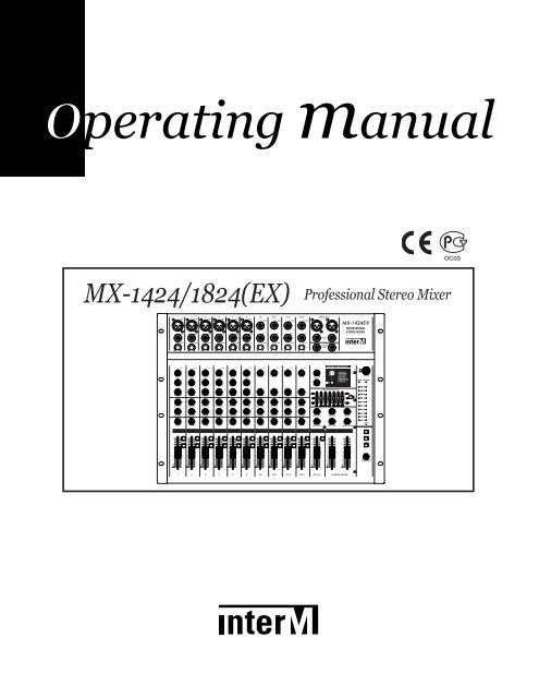
MX-1424/1824(EX) Professional Stereo Mixer
MX-1424/1824(EX) Professional Stereo Mixer
MX-1424/1824(EX) Professional Stereo Mixer

Create successful ePaper yourself
Turn your PDF publications into a flip-book with our unique Google optimized e-Paper software.
OC03<br />
B370031<br />
<strong>MX</strong>-<strong>1424</strong>/<strong>1824</strong>(<strong>EX</strong>) <strong>Professional</strong> <strong>Stereo</strong> <strong>Mixer</strong>
Contents<br />
Welcome<br />
Warning.........................................................................................................................................1<br />
Unpacking......................................................................................................................................2<br />
Short Form Instructions.....................................................................................................................2<br />
Installation<br />
Environment....................................................................................................................................3<br />
Important Safety Instructions.............................................................................................................3<br />
Features............................................................................................................................................4<br />
Front Panel<br />
Mono Input Section..........................................................................................................................5<br />
<strong>Stereo</strong> Input Section.........................................................................................................................8<br />
Master Section ..............................................................................................................................10<br />
Rear Panel<br />
Input/ Output Section Connectors A ..............................................................................................13<br />
Input/ Output Section Connectors B ...............................................................................................14<br />
Point to Remember.......................................................................................................................15<br />
Connections ...................................................................................................................................16<br />
Grounding on the Road ..............................................................................................................17<br />
Applications ..................................................................................................................................19<br />
Block Diagram ..............................................................................................................................20<br />
Specifications<br />
General Specifications ...................................................................................................................21<br />
Input/Output Specifications............................................................................................................22<br />
Service<br />
Procedures....................................................................................................................................23<br />
Schematic.....................................................................................................................................23<br />
Parts List .......................................................................................................................................23<br />
Variations and Options ...............................................................................................................23<br />
Warranty .......................................................................................................................................23
PROFESSIONAL STEREO MIXER<br />
Welcome<br />
A personal welcome to you from the management and employees of Inter-M<br />
All of the co-workers here at Inter-M are dedicated to providing excellent products with inherently good value,<br />
and we are delighted you have purchased one of our products.<br />
We sincerely trust this product will provide years of satisfactory service, but if anything is not to your<br />
complete satisfaction, we will endeavor to make things right.<br />
Welcome to Inter-M, and thank you for becoming part of our worldwide extended family!<br />
CAUTION<br />
RISK OF ELECTRIC SHOCK<br />
DO NOT OPEN<br />
This symbol is intended to alert the user to the<br />
presence of uninsulated “dangerous voltage” within<br />
the product’s enclosure that may be of suf-ficient<br />
magnitude to constitute a risk of electric shock to<br />
persons.<br />
CAUTION: TO REDUCE THE RISK OF ELECTRIC SHOCK.<br />
DO NOT REMOVE COVER (OR BACK).<br />
NO USER-SERVICEABLE PARTS INSIDE.<br />
REFER SERVICING TO QUALIFIED SERVICE PERSONNEL.<br />
Caution:<br />
This symbol is intended to alert the user to the<br />
presence of important operation and mainte-nance<br />
(servicing) instructions in the literature accompanying<br />
the appliance.<br />
To prevent electric shock do not use this (polarized) plug with<br />
an extension cord, receptacle or other outlet unless the blades<br />
can be fully inserted to prevent blade expo-sure.<br />
WARNING<br />
To prevent fire or shock hazard, do not<br />
expose the unit to rain or moisture.<br />
Attentions: Pour prévenir les chocs électriques ne pas utiliser cette<br />
fiche polarisée avec un prolongateur, une prise de courant<br />
on une autre sortie de courant, sauf si les lames peuvent<br />
étre insérées à fond sans en laisser aucune partie à<br />
découvert.<br />
*Do not install this equipment in a confined space such as a book case or similar unit.<br />
*The apparatus shall not be exposed to dripping or splashing and no objects filled with liquids, such vases, shall be placed on the apparatus.<br />
*Worded: “WARNING FOR YOUR PROTECTION PLEASE READ THE FOLLOWING-WATER AND MOISTURE: Unit should not be used<br />
near water(e.g. near a bathtub, washbowl, kitchen sink, laundry tub, in a wet basement, or near a swimming pool, etc). Care should be taken<br />
so than objects do not fall and liquids are not spilled into the enclosure through openings.”<br />
<strong>MX</strong>-<strong>1424</strong>/<strong>1424</strong><strong>EX</strong>/<strong>1824</strong>/<strong>1824</strong><strong>EX</strong><br />
1
PROFESSIONAL STEREO MIXER<br />
Unpacking<br />
Although it is neither complicated to install nor difficult to operate your set, a few minutes of your time is<br />
required to read this manual for a properly wired installation and becoming familiar with its many features and<br />
how to use them.<br />
Please take a great care in unpacking your set and do not discard the carton and other packing materials.<br />
They may be needed when moving your set and are required if it ever becomes necessary to return your set<br />
for service. Never place the unit near radiators, in front of heating vents, to direct sun light, in excessive humid<br />
or dusty location to avoid early damage and for your years of quality entertainment. Connect your<br />
complementary components as illustrated in the following page.<br />
Short Form Instructions<br />
Thank you for purchasing a <strong>MX</strong> 4Bus SERIES Mixing Console. The <strong>MX</strong> 4Bus Series provides an excellent balance<br />
of operability, functionally and ease of use. In order to take full advantage of the <strong>MX</strong> 4Bus Series capabilities<br />
and enjoy years of trouble - free use, please read this manual carefully.<br />
2 <strong>MX</strong>-<strong>1424</strong>/<strong>1424</strong><strong>EX</strong>/<strong>1824</strong>/<strong>1824</strong><strong>EX</strong>
PROFESSIONAL STEREO MIXER<br />
Installation<br />
Environment<br />
Never place this product in an environment which could alter its performance or reduce its service life. Such<br />
environments usually include high levels of heat, dust, moisture, and vibration.<br />
Important Safety Instructions<br />
1. Read these instructions.<br />
2. Keep these instructions.<br />
3. Heed all warnings.<br />
4. Follow all instructions.<br />
5. Do not use this apparatus near water.<br />
6. Clean only with dry cloth.<br />
7. Do not block any ventilation openings. Install in accordance with the manufacturer’s instructions.<br />
8. Do not install near any heat sources such as radiators, heat registers, stoves, or other apparatus (including<br />
amplifiers) that produce heat.<br />
9. Do not defeat the safety purpose of the polarized or grounding-type plug. A polarized plug has two blades<br />
with one wider than the other. A grounding type plug has two blades and a third grounding prong. The wide<br />
blade or the third prong are provided for your safety. If the provided plug does not fit into your outlet, consult<br />
an electrician for replacement of the obsolete outlet.<br />
10. Protect the power cord from being walked on or pinched particularly at plugs, convenience receptacles, and<br />
the point where they exit from the apparatus.<br />
11. Only use attachments/accessories specified by the manufacturer.<br />
12. Use only with the cart, stand, tripod, bracket, or table specified by the manufacturer, or sold with the apparatus.<br />
When a cart is used, use caution when moving the cart/apparatus combination to avoid injury from tip-over.<br />
13. Unplug this apparatus during lightning storms or when unused for long periods of time.<br />
14. Refer all servicing to qualified service personnel. Servicing is required when the<br />
apparatus has been damaged in any way, such as power-supply cord or plug is<br />
damaged, liquid has been spilled or objects have fallen into the apparatus, the<br />
apparatus has been exposed to rain or moisture, does not operate normally, or has<br />
been dropped.<br />
S3125A<br />
- AVOID <strong>EX</strong>CESSIVE HEAT, HUMIDITY, DUST AND VIBRATION<br />
Keep the unit away from locations where it is likely to be exposed to high temperatures or humidity-such as<br />
near radiators, stoves, etc. Also avoid locations which are subject to excessive dust accumulation, or to<br />
vibration that could cause mechanical damage.<br />
- AVOID PHYSICAL SHOCKS<br />
Strong physical shocks to the unit may cause damage. Handle the unit with care.<br />
- DO NOT OPEN THE CASE OR ATTEMPT REPAIRS OR MODIFICATIONS YOURSELF<br />
This product contains no user-serviceable parts. Refer all maintenance to qualified Inter-M service personnel.<br />
Opening the case and/or tampering with internal circuitry voids the warranty.<br />
- ALWAYS POWER OFF BEFORE MAKING CONNECTIONS<br />
Always turn the AC mains OFF before connecting or disconnecting cables. This is important to prevent<br />
damage to the unit itself as well as other connected equipment.<br />
- HANDLE CABLES CAREFULLY<br />
Always plug and unplug cables (including the AC mains power cord) by gripping the connector, not the cord.<br />
- CLEAN WITH A SOFT DRY CLOTH<br />
Never use solvents such as benzine or paint thinner to clean the unit. Wipe clean with a soft, dry cloth.<br />
<strong>MX</strong>-<strong>1424</strong>/<strong>1424</strong><strong>EX</strong>/<strong>1824</strong>/<strong>1824</strong><strong>EX</strong><br />
3
PROFESSIONAL STEREO MIXER<br />
Features<br />
- 6MONO(<strong>MX</strong>-<strong>1424</strong>/<strong>1424</strong><strong>EX</strong>), 10MONO(<strong>MX</strong>-<strong>1824</strong>/<strong>1824</strong><strong>EX</strong>)INPUT AND 4 STEREO INPUT<br />
Any sound source of microphones, cassette decks, electronic guitars, organs can be applied to the channel input.<br />
- MAIN MIX L/R AND ALT 3/4 OUTPUT<br />
Main mix L/R and ALT 3/4 are provided for convenient use.<br />
- 2 AUX RETURN AND 2 AUX SEND<br />
For convenient use of external equipment, AUX SEND and AUX RETURN function are provided.<br />
- CHANNEL EQUALIZER<br />
The 3 band equalizer are designed for ±15dB control on mono input channel.<br />
The 2 band equalizer are designed for ±15dB control on stereo input channel.<br />
- SOLO FUNCTION OF ALL CHs<br />
The SOLO function allows you to monitor through headphone outputs and control room outputs any input<br />
channel after the channel fader.<br />
- 7BAND GRAPHIC EQUALIZER(ONLY <strong>1424</strong><strong>EX</strong>/<strong>1824</strong><strong>EX</strong>)<br />
For easy sound tuning with musical instrument, 7band graphic equalizer is provided.<br />
- DSP FUNCTION : 8 PROGRAMMED EFFECT(ONLY <strong>1424</strong><strong>EX</strong>/<strong>1824</strong><strong>EX</strong>)<br />
Built-in, 24-bit DSP with 8 Selectable Presets including Reverb, Delay and Chorus.<br />
- PHANTOM POWER(+48V)<br />
Phantom power is provided for easy connection of condenser microphones requiring an external power supply.<br />
4 <strong>MX</strong>-<strong>1424</strong>/<strong>1424</strong><strong>EX</strong>/<strong>1824</strong>/<strong>1824</strong><strong>EX</strong>
PROFESSIONAL STEREO MIXER<br />
Front Panel<br />
1. MONO INPUT SECTION<br />
1<br />
2<br />
3<br />
4<br />
1. MIC INPUT<br />
A 3-pin XLR-type connector is used for balanced low<br />
impedance microphone inputs. (1: sleeve, 2: hot, 3: cold)<br />
Microphones of 50-600Ω line level devices can be connected<br />
here.<br />
When the PHANTOM switch is turned on, DC +48V will be<br />
supplied to pins 2 and 3 of these connectors.<br />
It is important that, during operation or testing of the mixer,<br />
all channel faders remain fully down whenever the mic input<br />
is not properly terminated with a microphone or equivalent<br />
150-ohm source.<br />
An open mic invites the introduction of high noise levels<br />
which could produce lower quality sound or an incorrect test<br />
measurement.<br />
5<br />
6<br />
7<br />
2 1<br />
3<br />
PHASE (Normal)<br />
1. GND<br />
2. ( + )<br />
3. ( )<br />
PHASE (Reverse)<br />
1. GND<br />
2. ( )<br />
3. ( + )<br />
8<br />
MIC Input Jack Pin<br />
9<br />
2<br />
10<br />
+48V<br />
11<br />
2<br />
1<br />
0V<br />
GROUND<br />
3<br />
+48V<br />
Phantom Power<br />
3<br />
<strong>MX</strong>-<strong>1424</strong>/<strong>1424</strong><strong>EX</strong>/<strong>1824</strong>/<strong>1824</strong><strong>EX</strong><br />
5
PROFESSIONAL STEREO MIXER<br />
2. BALANCED LINE INPUT CONNECTORS<br />
A standard 1/4" phone jack is used for balanced or unbalanced line level signals. Examples of line level<br />
signals include most electronic keyboards, synthesizers, turn-tables(with appropriate pre-amps), tape decks<br />
and the line outputs from other mixers. All input channel controls, including the variable GAIN control.<br />
TIP(Hot)<br />
SLEEVE(GND)<br />
RING(COLD)<br />
(1/4" Phone 3 Section Connector)<br />
3. GAIN CONTROL (TRIM)<br />
According to the level of the input signal, use this knob to adjust the input to an appropriate level. The best<br />
balance of S/N and dynamic range will be achieved if you adjust the TRIM control so that the peak indicator<br />
lights occasionally.<br />
This control adjusts the channel's mic input sensitivity between -60dB and -16dB and the line input sensitivity<br />
between -30dB and +14dB.<br />
4. PEAK LED INDICATOR<br />
This LED indicators let you check the level of the signal input to the channel. The peak indicator lights when<br />
the input signal reaches 3dB below the channel s clipping point. This indicator show the level of the Post-EQ/<br />
pre-fader signal. If the PEAK indicator lights more than briefly on high-level transients, you should use the<br />
GAIN control to decrease the input sensitivity of the channel. If this dose not work, reduce the output level of<br />
the connected source.<br />
5. 3BAND EQUALIZER CONTROLS<br />
This is a 3-band equalizer with center frequencies, range and type as shown below. The frequency response<br />
is flat when the knob is in the "▼"position.<br />
CONTROL<br />
HIGH<br />
MID<br />
LOW<br />
MAX. BOOST/CUT<br />
±15dB<br />
±12dB<br />
±15dB<br />
FREQUENCY<br />
12kHz<br />
2.5kHz<br />
80Hz<br />
TYPE<br />
Shelving<br />
Peaking<br />
Shelving<br />
6. AUX 1 CONTROLS<br />
This knobs control the level of the signals sent to AUX 1 bus.<br />
This control is placed before the channel fader, it will be not affected by the channel fader.<br />
7. AUX 2 CONTROLS<br />
This knobs control the level of the signals sent to AUX 2 bus. The channel signals mixed by this bus have their<br />
overall level set by the AUX 2 SEND Control to the AUX SEND 2 jack on the rear panel. The Aux 2 bus<br />
signal is also fed into the internal digital signal processor(only <strong>MX</strong>-<strong>1424</strong><strong>EX</strong>/<strong>1824</strong><strong>EX</strong>).<br />
Since this control is placed after the channel fader, the signal level will be affected by the channel fader setting.<br />
6 <strong>MX</strong>-<strong>1424</strong>/<strong>1424</strong><strong>EX</strong>/<strong>1824</strong>/<strong>1824</strong><strong>EX</strong>
PROFESSIONAL STEREO MIXER<br />
※ Modifications<br />
Mono channel Aux send 2 are post-fader. This modification changes Aux send2 to be pre-fader instead of<br />
post-fader Mono channel.<br />
- Aux send2 : post-fader pre-fader<br />
If you want to convert them, carry out the modification described below to each mono channel you want to<br />
be altered. See below figure.<br />
1) Power switch off, Remove AC cord.<br />
The work area is on the underside of the PCB board near the channel AUX SEND2 knob.<br />
2) Cut the PCB Line<br />
3) Add a Jumper<br />
AUX2<br />
AUX2<br />
POST<br />
POST<br />
Cut the PCB Line<br />
PRE<br />
PRE<br />
Add a Jumper<br />
Before<br />
After<br />
8. PAN CONTROL<br />
This control pans the channel signal across the master L and R buses, thus determining the perceived position<br />
of the sound from that channel in the output stereo sound field. If a PAN control is set all the way to the left,<br />
for example, the sound from that channel will be heard from the left speaker system only.<br />
If it is set all the way to the right, the sound will be heard from the right speaker system only.<br />
Intermediate settings will cause the sound to appear at corresponding locations in the stereo sound field.<br />
9. MUTE/ALT 3-4 SWITCH<br />
When the Mute/ALT 3-4 switch is depressed, a channel output will be routed to the ALT 3-4 output instead<br />
of the main mix.<br />
ALT 3-4 bus offers you a second independent stereo submix with its own submaster stereo fader.<br />
10. SOLO SWITCH<br />
When these switch is depressed, the channel input signal can be routed to the solo bus.<br />
This switch allows you to monitor the post-fader channel input signal through headphone outputs and control<br />
room outs.<br />
11. CHANNEL FADER<br />
This is the channels main level control. It determines the level of the signal that is sent from the channel to the<br />
master mixing and effect buses. It is the settings of the input channel faders that determine the mix, or the<br />
balance of sound levels between the instruments or other sources connected to the inputs.<br />
When a channel is not being used, its fader should be set at the minimum position to prevent the addi-tion of<br />
unwanted noise to the main program signal.<br />
<strong>MX</strong>-<strong>1424</strong>/<strong>1424</strong><strong>EX</strong>/<strong>1824</strong>/<strong>1824</strong><strong>EX</strong><br />
7
PROFESSIONAL STEREO MIXER<br />
2. STEREO INPUT SECTION<br />
1<br />
2<br />
3<br />
4<br />
5<br />
6<br />
7<br />
1. STEREO INPUT JACKS<br />
These are unbalanced 1/4" phone jacks which input a stereo<br />
source with a nominal input and impedance of +4dB/600Ω.<br />
If a plug is inserted only in L/MONO, the same signal will be<br />
sent to both the L and R buses.<br />
The nominal input level for these jacks is -20dB ~ +14dB.<br />
2. GAIN CONTROL (TRIM)<br />
According to the level of the input signal, use this knob to<br />
adjust the input to an appropriate level. The best balance of<br />
S/N and dynamic range will be achieved if you adjust the<br />
TRIM control so that the peak indicator lights occasionally.<br />
This control adjusts the channel's input sensitivity between -<br />
20dB and +14dB.<br />
3. PEAK LED INDICATORS<br />
This LED indicators let you check the level of the signal input<br />
to the channel. The peak indicator lights when the input signal<br />
reaches 3dB below the channels clipping point.<br />
This indicator show the level of the post-EQ/pre-fader signal.<br />
If the PEAK indicator lights more than briefly on high-level<br />
transients, you should use the GAIN control to decrease the<br />
input sensitivity of the channel. If this dose not work, reduce<br />
the output level of the connected source.<br />
4. 2 BAND EQUALIZER CONTROLS<br />
This is a 3-band equalizer with center frequencies, range,<br />
and type as shown below. The frequency response is flat<br />
when the knob is in the "▼"position.<br />
CONTROL<br />
MAX. BOOST/CUT<br />
FREQUENCY<br />
TYPE<br />
8<br />
9<br />
HIGH<br />
LOW<br />
±15dB<br />
±15dB<br />
12kHz<br />
80Hz<br />
Shelving<br />
Shelving<br />
10<br />
5. AUX 1 CONTROL<br />
This knobs control the level of the signals sent to AUX 1 bus.<br />
This control is placed before the channel fader, it will be not<br />
affected by the channel fader.<br />
8 <strong>MX</strong>-<strong>1424</strong>/<strong>1424</strong><strong>EX</strong>/<strong>1824</strong>/<strong>1824</strong><strong>EX</strong>
PROFESSIONAL STEREO MIXER<br />
6. AUX 2 CONTROLS<br />
This knobs control the level of the signals sent to AUX 2 bus.<br />
The channel signals mixed by this bus have their overall level set by the AUX2 SEND Control to the AUX<br />
SEND 2 jack on the rear panel.<br />
The aux2 bus signal is also fed into the internal digital signal processor(only <strong>MX</strong>-<strong>1424</strong><strong>EX</strong>/<strong>1824</strong><strong>EX</strong>).<br />
Since this control is placed after the channel fader, the signal level will be affected by the channel fader<br />
setting.<br />
7. BALANCE CONTROL<br />
This control adjusts the balance or the L/R position of the stereo input signal.<br />
Turning the BALANCE control to the left of center moves the apparent source toward the MAIN MIX L bus,<br />
turning it to the right moves the source toward the MAIN MIX R bus.<br />
8. MUTE/ALT 3-4 SWITCH<br />
When the Mute/ALT 3-4 switch is depressed, a channel output will be routed to the ALT 3-4 output instead<br />
of the main mix.<br />
ALT 3-4 bus offers you a second independent stereo submix with its own submaster stereo fader.<br />
9. SOLO SWITCH<br />
When these switch are engaged, the channel input signal can be routed to the solo bus.<br />
This switch allows you to monitor the post-fader channel input signal through headphone outputs and control<br />
room outs.<br />
10. CHANNEL FADER<br />
This is the channel s main level control. It determines the level of the signal that is sent from the channel to the<br />
master mixing and effect buses. It is the settings of the input channel faders that determine the mix, or the<br />
balance of sound levels between the instruments or other sources connected to the inputs.<br />
When a channel is not being used, its fader should be set at the minimum position to prevent the addi-tion of<br />
unwanted noise to the main program signal.<br />
<strong>MX</strong>-<strong>1424</strong>/<strong>1424</strong><strong>EX</strong>/<strong>1824</strong>/<strong>1824</strong><strong>EX</strong><br />
9
PROFESSIONAL STEREO MIXER<br />
3. MASTER SECTION<br />
1. MAIN MIX OUTPUTS<br />
These are balanced XLR type output jacks with a<br />
nominal output/impedance of +4dB/600Ω.<br />
These connectors transmit the MIX L/R outputs to the<br />
power amplifiers. which drives the main speakers.<br />
2. MAIN INSERT L/R JACKS<br />
The insert jack sends one signal to the processing<br />
device and inserts the returned signal back into the<br />
Left and Right main mix signal paths.<br />
The nominal input level and impedance is<br />
0dB/600Ω and the nominal output level and<br />
impedance is 0dB/10kΩ<br />
3. CONTROL ROOM OUT JACKS<br />
These are unbalanced 1/4" phone jack with a<br />
nomina output and impedance of +4dB/600Ω.<br />
This is where you connect your control room<br />
monitor amplifier inputs.<br />
※ No. 4~7 are applied only to <strong>MX</strong>-<strong>1424</strong><strong>EX</strong>/<strong>1824</strong><strong>EX</strong><br />
4. DSP OUTPUT CONTROLS<br />
These controls adjusts the level of the return signal<br />
which is sent from the internal digital effect to the<br />
mix L/R bus or aux1 bus.<br />
5. DSP PROGRAM SELECT SWITCH<br />
The program knob selects one of the 8 built-in<br />
digital effects, for each number you select.<br />
24 Bit Digital Effects processor with high quality,<br />
studio grade effects like Delay, Chorus and Reverb.<br />
6. DSP ON/ OFF SWITCH<br />
This switch turns the internal digital effect on/off.<br />
7. STEREO GRAPHIC EQUALIZER<br />
The <strong>MX</strong>-<strong>1424</strong><strong>EX</strong>/<strong>1824</strong><strong>EX</strong> Series internal stereo<br />
graphic equalizer (GEQ) allows the fine response<br />
shaping of the main program output.<br />
This section has seven linear controls, corresponding<br />
to center frequencies of 63Hz, 160Hz,<br />
400Hz, 1kHz, 2.5kHz, 6.4kHz, 15kHz.<br />
Each control permits a maximum boost or cut of<br />
12dB. When a control is set to the center or 0<br />
position, the response in the corresponding band is<br />
unaffected.<br />
10 <strong>MX</strong>-<strong>1424</strong>/<strong>1424</strong><strong>EX</strong>/<strong>1824</strong>/<strong>1824</strong><strong>EX</strong>
PROFESSIONAL STEREO MIXER<br />
8. GRAPHIC EQUALIZER ON/ OFF SWITCH<br />
This switch turns the graphic equalizer on and off.<br />
13<br />
14<br />
15<br />
16<br />
17<br />
18<br />
19<br />
9. AUX SEND 1 ~ 2 CONTROL<br />
These controls adjusts the level of the aux send 1~ 2 output.<br />
10. AUX RETURN 1~ 2 CONTROL<br />
This control adjusts the input levels from the effect units etc.<br />
Connected to the L/MONO, R jacks of AUX RETURN 1~ 2<br />
are sent to the MIX L/R buses.<br />
If a plug is inserted into only the L/MONO jack, the same<br />
signal will be sent to L/R BALANCE control.<br />
11. TAPE IN CONTROL<br />
This control adjusts the level of the playback signal that is<br />
inserted to the master mixing bus from the TAPE IN jacks on<br />
the top panel.<br />
12. CTRL ROOM CONTROL<br />
This is a stereo level control for the studio monitor.<br />
This circuit monitors the left/right SOLO buses.<br />
13. HEADPHONES OUTPUT JACK (1/4" TRS STEREO JACK)<br />
These jacks (tip=left, ring=right, sleeve=GND) may be connected<br />
to external power amplifiers for headphone<br />
distribution, or you can plug our phones directly into the<br />
jack. Use only stereo phones!<br />
When a mono connector is plugged into the stereo connector,<br />
it connects both sides of the headphone amplifier to a<br />
single load. In any professional audio system, acci-dents can<br />
happen and will have built in protection cir-cuits to assure<br />
that momentary problems will not cause failure. However,<br />
this circuit will fail in 2-3 minutes if this caution is not<br />
observed.<br />
( O )<br />
( X )<br />
(1/4" Phone 3 Section Connector)<br />
(1/4" Phone 2 Section Connector)<br />
14. POWER INDICATOR<br />
This indicator lights when the power switch is turned on.<br />
15. PHANTOM POWER INDICATOR<br />
This indicator lights when the phantom power switch is turned on.<br />
<strong>MX</strong>-<strong>1424</strong>/<strong>1424</strong><strong>EX</strong>/<strong>1824</strong>/<strong>1824</strong><strong>EX</strong><br />
11
PROFESSIONAL STEREO MIXER<br />
16. OUTPUT LEVEL METER<br />
A vertical row of ten LED show the continuous output level of main Output L/R or monitor 1/2 by signal<br />
select switch. This type of display is free from over shoot problem of mechanical meters and is highly visible<br />
under poor lighting conditions. The 0 LED means an output level of +4dB for +4dB output (that s the rated<br />
level).<br />
17. SOLO INDICATOR<br />
This indicator lights when the solo switch is turned on.<br />
18. CTRL, HEADPHONE MONITOR SELECTOR<br />
These switches select the output signal for the Ctrl room out jack and Phones out jack.<br />
Three push buttons to select form the following signal source : Tape in, ALT 3/4, Main mix L/R.<br />
19. PHONE GAIN CONTROL<br />
This control sets the level at the headphone jack.<br />
20. TO MIX SWITCH<br />
When this switch is on the signal of each ALT 3/4 will be sent to the MIX L/R buses.<br />
21. ALT 3/4 OUTPUT FADER<br />
This fader adjusts the final level of the combined stereo signal and send the ALT 3/4 output jacks.<br />
22. MAIN MIX L/R MASTER FADERS<br />
These faders adjust the final level of the combined signals from all channels.<br />
12 <strong>MX</strong>-<strong>1424</strong>/<strong>1424</strong><strong>EX</strong>/<strong>1824</strong>/<strong>1824</strong><strong>EX</strong>
PROFESSIONAL STEREO MIXER<br />
Rear Panel<br />
1. INPUT/OUTPUT CONNECTORS A<br />
1. CHANNEL INSERT I/O JACK<br />
These are input/output jacks located between the head-amplifier and the high pass filter.<br />
The nominal input level and impedance is 0dB/600Ω, and the nominal output level and impedance is<br />
0dB/10kΩ. These jacks allow you to own graphic equalizers, compressors, noise filters, or other devices.<br />
Tip:Output(Send to external device)<br />
Sleeve:Ground<br />
Ring:Input(Return from external device)<br />
2. TAPE IN JACKS<br />
Used to connect a stereo output device such as external cassette recorder or CD player.<br />
The signals which are input here are sent to the ST bus.<br />
3. REC OUT JACKS<br />
The REC OUT jacks send the unequalized pre-fader signal from the master bus for recording by the tape<br />
deck.<br />
<strong>MX</strong>-<strong>1424</strong>/<strong>1424</strong><strong>EX</strong>/<strong>1824</strong>/<strong>1824</strong><strong>EX</strong><br />
13
PROFESSIONAL STEREO MIXER<br />
2. INPUT/OUTPUT CONNECTORS B<br />
1. POWER SWITCH<br />
This switch turns the power ON/OFF. When in the ON position, the power indicator will light.<br />
2. PHANTOM POWER SWITCH<br />
When is the ON position, +48V DC phantom power will be provided between pin 2 and pin 3 of the XLRtype<br />
jack. If you do not need phantom power, be sure to turn this to the OFF position.<br />
3. ALT 3/4 OUTPUT JACKS<br />
These are unbalanced 1/4" phone type output jacks which output the signals of ALT 3/4 buses with a<br />
nominal output/impedance of +4dB/600Ω.<br />
4. AUX SEND 1 ~ 2 JACKS<br />
These are unbalanced 1/4" phone jacks with a nominal output and impedance of +4dB/600Ω.<br />
The AUX SEND 1~ 2 output signal is the sum of all of the input channel AUX SEND 1~ 2 buses.<br />
5. AUX RETURN 1~ 2 JACKS<br />
These are unbalanced 1/4" phone jacks with a nominal level and impedance of +4dB/10kΩ.<br />
These jacks are usually used to receive the audio returned from an effect unit such as reverb or delay, but<br />
they can also be used as supplementary inputs.<br />
If a plug is inserted only in L/MONO, the same signal will be sent to both the L and R buses.<br />
These allow you to return signal from outboard devices, either in stereo pairs or mono phonically (many<br />
popular effects processors provide a single mono input but have a pair of stereo outputs).<br />
In practice, you'll probably want to use the Auxiliary returns to bring in signal from connected effect<br />
processors. If the effects processors have stereo outputs, they should be connected to both the left and right<br />
Auxiliary return inputs so that their stereo integrity is retained. If they have mono outputs, you can route them<br />
to either the left or right inputs and then use the Auxiliary return Balance control to adjust the relative level of<br />
each paired signal.<br />
14 <strong>MX</strong>-<strong>1424</strong>/<strong>1424</strong><strong>EX</strong>/<strong>1824</strong>/<strong>1824</strong><strong>EX</strong>
PROFESSIONAL STEREO MIXER<br />
Points to Remember<br />
- In all cases, use good quality twin screened audio cable. Check for instability at the output.<br />
- Always connect both conductors at both ends, and ensure that the screen is only connected at one end.<br />
- Do not disconnect the mains earth from each piece of equipment. This is needed to provided both safety and<br />
screen returns to the system star point.<br />
- Equipment which has balanced inputs and outputs may need to be electrically isolated from the equipment<br />
rack and/or other equipment, to avoid earth loops.<br />
It is important to remember that all equipment which is connected to the mains it a potential source of hum and<br />
interference and may radiate both electrostatic or electromagnetic radiation. In addition, the mains will also act<br />
as a carrier for many forms of RF interference generated by electric motors, air-conditioning units, thyristor light<br />
dimmers etc. Unless the earth system is clean, all attempts to improve hum noise levels will be futile. In extreme<br />
cases there will be no alternative but to provide a completely separate and independent ‘technical earth’ to<br />
replace the incoming ‘noisy earth’.<br />
However, always consult your local electricity supply authority to ensure that safety regulations are not being<br />
infringed.<br />
<strong>MX</strong>-<strong>1424</strong>/<strong>1424</strong><strong>EX</strong>/<strong>1824</strong>/<strong>1824</strong><strong>EX</strong><br />
15
PROFESSIONAL STEREO MIXER<br />
Connections<br />
Inter-M products are wired to reflect accepted wiring practices used throughout the world.<br />
Balanced XLR connectors are wired as described:<br />
Pin #1 Shield<br />
Pin #2 Positive<br />
Pine #3 Negative<br />
Balanced 1/4" TRS connectors are wired as described:<br />
Tip is Positive<br />
Ring is Negative<br />
Sleeve is Shield<br />
Hot (positive)<br />
2<br />
Hot (positive)<br />
Cold (negative)<br />
Screen<br />
3<br />
Cold (negative)<br />
Sleeve<br />
1<br />
Balanced Input<br />
Insert Points<br />
Sleeve<br />
Ring<br />
Screen<br />
Return<br />
Send<br />
Tip<br />
Sleeve<br />
Ring<br />
Tip<br />
Amp/Line Input<br />
Hot (positive)<br />
Cold (negative)<br />
Screen<br />
3 Pole (<strong>Stereo</strong>) Jack<br />
Sleeve<br />
Ring<br />
Tip<br />
Headphones<br />
Left Signal<br />
Right Signal<br />
Ground<br />
Unbalanced<br />
Input/Output<br />
AUX Send<br />
Seeve<br />
Tip<br />
Signal<br />
Ground<br />
2 Pole (Mono) Jack<br />
16 <strong>MX</strong>-<strong>1424</strong>/<strong>1424</strong><strong>EX</strong>/<strong>1824</strong>/<strong>1824</strong><strong>EX</strong>
PROFESSIONAL STEREO MIXER<br />
Grounding on the Road<br />
Many of the above procedures are difficult to use on the road. For example, the telescoping shield concept is<br />
nearly impossible to use on a portable cable. Similarly, it is a difficult and time consuming process to search for<br />
a water pipe ground every time the system is moved from one performance to another. Yet portable systems can<br />
be extremely complex, and may have major grounding problems. The telescoping shield concept can be<br />
extended to portable systems by installing a ”ground lift switch” on the output of each device, and on the inputs<br />
of devices after the mixer. Since microphones are not grounded except through the mixer, there is on need for<br />
an input ground lift switch on most mixers. The diagram below shows a typical ground lift switch installation. By<br />
judicious use of these switches, each piece of equipment can be AC grounded for safety without causing ground<br />
loops.<br />
Because of leakage currents from equipment in the audio system, and in the house, some noise currents can ride<br />
on the AC ground wire and are able to enter the audio system. This problem is usually most noticeable with<br />
sensitive equipment such as the mixer.Lifting the AC ground at the mixer can often solve this problem. However,<br />
lifting the AC ground on the mixer also lifts the AC ground on the microphone chassis, causing a safety hazard.<br />
Try connecting the mixer and any other sensitive equipment to other AC circuits. The only other apparent<br />
solution to this problem is to eliminate the noise on the AC ground, which is not an easy task. Since it has its<br />
own ground, a portable AC power distribution system connected to the house service entrance may be the most<br />
effective way to avoid all AC noises. Such a system can be designed and constructed by a qualified electrician;<br />
check local electrical codes before each use.<br />
USE OF GROUND LIFT SWITCH<br />
Balanced Portable Cable with Shield Intact<br />
Devices with Balanced Inputs & Outputs<br />
Ground Lift Switch<br />
Installed in Box or<br />
on Rack Panel<br />
Main AC Ground<br />
Perhaps the best answer to portable system grounding problems, PFI, EMI, and AC noise, is to develop a<br />
versatile grounding scheme. Ground lift switches and adapters, and a portable AC power distribution system<br />
allow different grounding techniques to be tried easily and quickly when a problem occurs.<br />
<strong>MX</strong>-<strong>1424</strong>/<strong>1424</strong><strong>EX</strong>/<strong>1824</strong>/<strong>1824</strong><strong>EX</strong><br />
17
PROFESSIONAL STEREO MIXER<br />
CONNECTOR AND CABLE CONFIGURATIONS<br />
REMOTE DEVICE<br />
REMOTE SIDE OF CABLE<br />
DESCRIPTION CABLE (Connector Type)<br />
2<br />
White(Red)/HIGH<br />
Black/LOW<br />
2<br />
Floating or Balanced<br />
low impedance: most<br />
professional equipment<br />
line in and line out,<br />
microphones.<br />
A. XLR**<br />
3<br />
1<br />
T R S<br />
Shield/GND<br />
White(Red)/HIGH Black/LOW<br />
1<br />
2<br />
3<br />
(XLR)<br />
B. TRS PHONE<br />
Shield/GND<br />
1<br />
3<br />
(XLR)<br />
Unbalanced<br />
C. STANDARD<br />
low impedance: some PHONE<br />
professional equipment<br />
and microphones.<br />
T<br />
S<br />
White(Red)/HIGH<br />
Shield/GND<br />
Black/LOW<br />
2<br />
1<br />
3<br />
(XLR)<br />
D. STANDARD<br />
PHONE<br />
Unbalanced<br />
high impedance: most<br />
hi-fi equipment.<br />
T<br />
S<br />
White(Red)/HIGH<br />
Shield/GND<br />
Black/LOW<br />
2<br />
1<br />
3<br />
(XLR)<br />
White(Black)/HIGH<br />
E. SHIELD/GND<br />
Unbalanced<br />
PHONE<br />
high impedance: most<br />
hi-fi equipment.<br />
T<br />
S<br />
Shield/GND<br />
S<br />
T<br />
(Standard Phone)<br />
Connector and cable configurations recommended for use with the <strong>MX</strong>-4 Bus Series.<br />
These cables are based on the use of auxiliary equipment that is isolated from the AC power mains.<br />
18 <strong>MX</strong>-<strong>1424</strong>/<strong>1424</strong><strong>EX</strong>/<strong>1824</strong>/<strong>1824</strong><strong>EX</strong>
PROFESSIONAL STEREO MIXER<br />
Applications<br />
<strong>MX</strong>-<strong>1424</strong>/<strong>1424</strong><strong>EX</strong>/<strong>1824</strong>/<strong>1824</strong><strong>EX</strong><br />
19
PROFESSIONAL STEREO MIXER<br />
Block Diagram<br />
20 <strong>MX</strong>-<strong>1424</strong>/<strong>1424</strong><strong>EX</strong>/<strong>1824</strong>/<strong>1824</strong><strong>EX</strong>
PROFESSIONAL STEREO MIXER<br />
Specifications.................................................*0dB=0.775Vrms, Specifications<br />
0dBV=1Vrms<br />
- GENERAL<br />
Maximum Output Level<br />
(0.5% T.H.D at 1kHz)<br />
T.H.D<br />
Frequency Response<br />
Hum and Noise<br />
(Average, Rs=150Ω)<br />
Maximum Voltage Gain<br />
Crosstalk (at 1kHz)<br />
Gain Control(mono Input Channel)<br />
Gain Control(stereo Input Channel)<br />
Input Channel Equalization<br />
LED Meters<br />
Channel Indicators<br />
Phantom Power<br />
Power Source/Power Consumption<br />
Weight<br />
Dimensions<br />
+24dB(MIX L/R) @600Ω<br />
+20dB(ALT 3/4, AUX1~ 2, CTRL ROOM) @600Ω<br />
+20dB(INSERT) @10kΩ<br />
More than 100mW(HEADPHONES) @40Ω<br />
PROFESSIONAL STEREO MIXER<br />
Specifications ..............................................0dB=0.775Vrms, 0dBV=1Vrms<br />
- INPUT<br />
Input Connector Input Impedance Nominal Impedance Rated Input Level Connector Type<br />
CH Mic 4kΩ 50 ~ 600Ω -60dB XLR 3-31 Type<br />
Balanced<br />
CH Line 10kΩ 600Ω -30dB Phone Jack (TRS)<br />
T = Hot<br />
R = Cold<br />
S = GND<br />
<strong>Stereo</strong> Input 5kΩ 600Ω -20dB Unbalanced<br />
Phone Jack<br />
Aux Return 1~ 2 10kΩ 600Ω +4dB Unbalanced<br />
Phone Jack<br />
Mono Channel Insert Input 10kΩ 600Ω 0dB Phone Jack (TRS)<br />
T = Out<br />
R = In<br />
S = GND<br />
Main <strong>Stereo</strong> Insert Input 10kΩ 600Ω 0dB Phone Jack (TRS)<br />
T = Out<br />
R = In<br />
S = GND<br />
Tape In 10kΩ 600Ω -10dBV RCA pin Jack<br />
- OUTPUT<br />
Output Output Nominal Rated<br />
Connector Impedance Impedance Output Level<br />
* Specifications and design subject to change without notice for improvements.<br />
Connector type<br />
MIX Out L/R 150Ω 600Ω +4dB XLR 3-32 Type<br />
ALT 3/4 75Ω 600Ω +4dB Unbalanced<br />
Phone Jack<br />
CTRL Room Out 75Ω 600Ω +4dB Unbalanced<br />
Phone Jack<br />
Aux Send 1~ 2 75Ω 600Ω +4dB Unbalanced<br />
Phone Jack<br />
Mono Channel Insert Input 600Ω 10kΩ 0dB Phone Jack (TRS)<br />
T = Out<br />
R = In<br />
S = GND<br />
Main <strong>Stereo</strong> Insert Input 10kΩ 600Ω 0dB Phone Jack (TRS)<br />
T = Out<br />
R = In<br />
S = GND<br />
Rec Out 600Ω 10kΩ -10dBV RCA pin Jack<br />
Phones Out 100Ω 40Ω 3mW <strong>Stereo</strong> Phone Jack<br />
22 <strong>MX</strong>-<strong>1424</strong>/<strong>1424</strong><strong>EX</strong>/<strong>1824</strong>/<strong>1824</strong><strong>EX</strong>
PROFESSIONAL STEREO MIXER<br />
Service<br />
Procedures<br />
Take steps to insure the problem is not related to operator error or other products within the system. Information<br />
provided in the troubleshooting portion of this manual may help with this process. Once it is certain that the<br />
problem is related to the product contact your warranty provider as described in the warranty section of this<br />
manual.<br />
Schematic<br />
A Schematic is available by contacting your warranty provider.<br />
Parts List<br />
A Parts List is available by contacting your warranty provider.<br />
Variations and Options<br />
Variations<br />
Products supplied through legitimate sources are compatible with local AC power requirements.<br />
Options<br />
No optional items are available for this product.<br />
Warranty<br />
Warranty terms and conditions vary by country and may not be the same for all products. Terms and conditions<br />
of warranty for a given product may be determined first by locating the appropriate country which the product<br />
was purchased in, then by locating the product type.<br />
To obtain specific warranty information and available service locations contact Inter-M directly or the<br />
authorized Inter-M Distributor for your specific country or region.<br />
<strong>MX</strong>-<strong>1424</strong>/<strong>1424</strong><strong>EX</strong>/<strong>1824</strong>/<strong>1824</strong><strong>EX</strong><br />
23
NOTE
Inter-M, Ltd. (Korea) began operations in 1983.<br />
Since then, Inter-M has grown to become one of the largest manufacturers<br />
of professional audio and commercial sound electronics equipment in the world.<br />
Inter-M has gained worldwide recognition for its own branded products,<br />
as well as private label manufacturing of electronics sold under other names (OEM).<br />
The company is no longer just a Korean company, but rather a global company<br />
that is truly international in scope, with factories and offices in Korea and China,<br />
and sales and marketing operations located in Japan, Europe, and the U.S.A.<br />
With more than 850 employees around the globe,<br />
Inter-M is well-poised for further growth and expansion.<br />
INTER-M AMERICAS, INC.<br />
1 EAST BEACON LIGHT LANE CHESTER, PA USA 19013-4409<br />
TEL : (610) 874-8870, FAX : (610) 874-8890<br />
Home Page : http://www.inter-m.net, E-mail : service@inter-m.net<br />
INTER-M Corporation<br />
SEOUL OFFICE:653-5 BANGHAK-DONG, DOBONG-KU, SEOUL, KOREA<br />
TEL : 82-2-2289-8140~8, FAX : 82-2-2289-8149<br />
Home Page : http://www.inter-m.com, E-mail : export@inter-m.com<br />
MADE IN CHINA<br />
December 2003 9007982200 A
![(Microsoft PowerPoint - Serialization.ppt [Mode de compatibilit\351])](https://img.yumpu.com/23429925/1/184x260/microsoft-powerpoint-serializationppt-mode-de-compatibilit351.jpg?quality=85)