Chapter 2 An Overview of ATM Network
Chapter 2 An Overview of ATM Network
Chapter 2 An Overview of ATM Network

Create successful ePaper yourself
Turn your PDF publications into a flip-book with our unique Google optimized e-Paper software.
<strong>Chapter</strong> 2<br />
<strong>An</strong> <strong>Overview</strong> <strong>of</strong> <strong>ATM</strong> <strong>Network</strong><br />
<strong>ATM</strong> is a form <strong>of</strong> packet switching technology. That is, <strong>ATM</strong> networks<br />
transmit their information in small, fixed length packets called “cell” each <strong>of</strong><br />
which contains 48-octets (or bytes) <strong>of</strong> data and 5-octets <strong>of</strong> header information.<br />
The small, fixed cell size was chosen to facilitate the rapid processing <strong>of</strong> packet<br />
in hardware and to minimize the amount <strong>of</strong> time required to fill a single packet.<br />
This is particularly important for real-time applications such as voice and video<br />
that require short packetization delays. <strong>ATM</strong> is the transfer mode for<br />
implementing Broadband Integrated Service Digital <strong>Network</strong>s (B-ISDN) [21].<br />
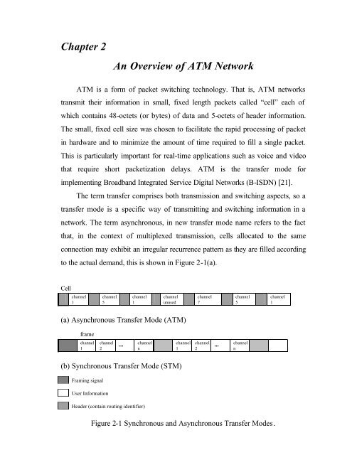
The term transfer comprises both transmission and switching aspects, so a<br />
transfer mode is a specific way <strong>of</strong> transmitting and switching information in a<br />
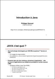
network. The term asynchronous, in new transfer mode name refers to the fact<br />
that, in the context <strong>of</strong> multiplexed transmission, cells allocated to the same<br />
connection may exhibit an irregular recurrence pattern as they are filled according<br />
to the actual demand, this is shown in Figure 2-1(a).<br />
Cell<br />
channel<br />
1<br />
channel<br />
5<br />
channel<br />
1<br />
channel<br />
unused<br />
channel<br />
7<br />
channel<br />
5<br />
channel<br />
1<br />
(a) Asynchronous Transfer Mode (<strong>ATM</strong>)<br />
frame<br />
channel<br />
1<br />
channel<br />
2<br />
...<br />
channel<br />
n<br />
channel<br />
1<br />
channel<br />
2<br />
...<br />
channel<br />
n<br />
(b) Synchronous Transfer Mode (STM)<br />
Framing signal<br />
User Information<br />
Header (contain routing identifier)<br />
Figure 2-1 Synchronous and Asynchronous Transfer Modes.
<strong>Chapter</strong> 2<br />
<strong>An</strong> overview <strong>of</strong> <strong>ATM</strong> <strong>Network</strong><br />
Figure 2-1 describes the difference between the Synchronous Transfer<br />
Mode (STM), and the Asynchronous Transfer Mode (<strong>ATM</strong>). As we have<br />
mentioned above that <strong>ATM</strong> is the data transfer interface for B-ISDN, let’s give<br />
short notes about B-ISDN standards.<br />
2-1 B-ISDN Standards<br />
In 1988, the telecommunication standardization sector <strong>of</strong> the ITU, the<br />
international standards agency commissioned by the United Nations for the<br />
global standardization <strong>of</strong> telecommunications, has developed a number <strong>of</strong><br />
standards for <strong>ATM</strong> networks. Other standards bodies and consortia (e.g., the<br />
<strong>ATM</strong> Forum, ANSI) have also contributed to the development <strong>of</strong> <strong>ATM</strong><br />
standards. The following subsection presents an overview <strong>of</strong> the standards, with<br />
particular emphasis on the protocol reference model used by <strong>ATM</strong> [22].<br />
2-1-1 Protocol Reference Model<br />
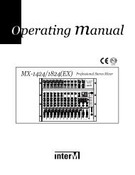
The B-ISDN protocol reference model, defined in ITU-T recommendation<br />
I-321, is shown in Figure 2-2 [23]. The purpose <strong>of</strong> the protocol reference model<br />
is to clarify the functions that <strong>ATM</strong> networks perform by grouping them into a<br />
set <strong>of</strong> interrelated, function-specific layers and planes. The reference model<br />
consists <strong>of</strong> a user plane, a control plane and a management plane (more details<br />
about these planes are in [24, 25, 26]. Within the user and control planes is a<br />
hierarchical set <strong>of</strong> layers. The user plane defines a set <strong>of</strong> functions for the transfer<br />
<strong>of</strong> user information between communication end-points; the control plane defines<br />
control functions such as call establishment, call maintenance, and call release,<br />
and the management plane defines the operations necessary to control<br />
information flow between planes and layers, and maintain accurate and faulttolerant<br />
network operation.<br />
9
<strong>Chapter</strong> 2<br />
<strong>An</strong> overview <strong>of</strong> <strong>ATM</strong> <strong>Network</strong><br />
Within the user and control planes, there are three layers; the physical layer, the<br />
<strong>ATM</strong> layer, and the <strong>ATM</strong> adaptation layer (AAL).<br />
Management Plane<br />
Control Plane<br />
User Plane<br />
Higher Layer Higher Layer<br />
<strong>ATM</strong> adaptation layer (AAL)<br />
Plane Management<br />
Layer Management<br />
<strong>ATM</strong> layer (<strong>ATM</strong>)<br />
Physical layer<br />
Figure 2-2 Protocol Reference Model for <strong>ATM</strong><br />
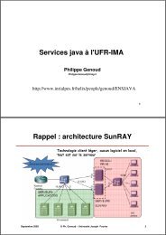
Table 2-1 summarizes the functions <strong>of</strong> each layer [23]. The physical layer<br />
performs primarily bit level functions, the <strong>ATM</strong> layer is primarily responsible for<br />
the switching <strong>of</strong> <strong>ATM</strong> cells, and the <strong>ATM</strong> adaptation layer is responsible for the<br />
conversion <strong>of</strong> higher layer protocol forms into <strong>ATM</strong> cells. The function that the<br />
physical, <strong>ATM</strong>, and adaptation layers perform are described in more detail in the<br />
following:<br />
Higher Layer Functions<br />
Higher Layers<br />
.convergence<br />
CS<br />
.segmentation and reassembly SAR AAL<br />
.generic flow control<br />
.cell-header generation/extraction<br />
<strong>ATM</strong> layer<br />
.cell VPI/VCI translation<br />
Layer .cell multiplex and demultiplex<br />
management .cell-rate decoupling<br />
.HEC, header-sequence generation/verification<br />
.cell delineation TC physical PHY<br />
.transmission-frame adaptation layer independent<br />
.transmission-frame generation/recovery<br />
bit timing PM PHY<br />
physical medium<br />
dependent<br />
AAL : <strong>ATM</strong> Adaptation layer.<br />
VCI : Virtual Channel Identifier.<br />
CS : Convergence Sublayer.<br />
HEC : Header Error Control.<br />
SAR : Segmentation <strong>An</strong>d Reassembly.<br />
TC : Transmission Control.<br />
VPI : Virtual Path Identifier.<br />
PM : Physical Medium<br />
Table 2-1 the Functions <strong>of</strong> B-ISDN in Relation to the B-ISDN PRM.<br />
10
<strong>Chapter</strong> 2<br />
<strong>An</strong> overview <strong>of</strong> <strong>ATM</strong> <strong>Network</strong><br />
2-1-2 Physical Layer<br />
The physical layer is divided into two sublayers: the physical medium<br />
sublayer, and the transmission convergence sublayer [23].<br />
2-1-2-1 Physical Medium (PM) sublayer<br />
The physical medium sublayer performs medium-dependent functions. For<br />
example, it provides bit transmission capabilities including bit alignment, line<br />
coding and electrical/optical conversion. The PM sublayer is also responsible for<br />
bit timing, i.e., the insertion and extraction <strong>of</strong> bit timing information. The PM<br />
sublayer currently supports two types <strong>of</strong> interface: optical and electrical.<br />
2-1-2-2 Transmission Convergence (TC) sublayer<br />
Above the physical medium sublayer is the transmissio n convergence<br />
sublayer, which is primarily responsible for framing <strong>of</strong> data transported over the<br />
physical medium. The ITU-T recommendation specifies two options for TC<br />
sublayer transmission frame structure: cell-based and Synchronous Digital<br />
Hierarchy (SDH). In the cell-based case, cells are transported continuously<br />
without any regular frame structure. Under SDH, cells are carried in a special<br />
frame structure based on the North American SONET (Synchronous Optical<br />
<strong>Network</strong>) protocol [27]. Regardless <strong>of</strong> which transmission frame structure is<br />
used, the TC sublayer is responsible for the following four functions: cell rate<br />
decoupling, header error control, cell delineation, and transmission frame<br />
adaptation. Cell rate decoupling is the insertion <strong>of</strong> idle cells at the sending side to<br />
adapt the <strong>ATM</strong> cell stream’s rate to the rate <strong>of</strong> the transmission path. Header<br />
error control is the insertion <strong>of</strong> an 8-bit CRC polynomial in the <strong>ATM</strong> cell header<br />
to protocol the contents <strong>of</strong> the <strong>ATM</strong> cell header. Cell delineation is the detection<br />
<strong>of</strong> cell boundaries. Transmission frame adaptation is the encapsulation <strong>of</strong><br />
11
<strong>Chapter</strong> 2<br />
<strong>An</strong> overview <strong>of</strong> <strong>ATM</strong> <strong>Network</strong><br />
departing cells into an appropriate framing structure (either cell-based or SDHbased).<br />
2-1-3 <strong>ATM</strong> Layer<br />
The <strong>ATM</strong> layer lies a top the physical layer and specifies the functions<br />
required for the switching and flow control <strong>of</strong> <strong>ATM</strong> cells [23].<br />
There are two interfaces in an <strong>ATM</strong> network; the user-network-interface<br />
(UNI) between the <strong>ATM</strong> end-point and the <strong>ATM</strong> switch, and the networknetwork<br />
interface (NNI) between two <strong>ATM</strong> switches. Although a 48-octets cell<br />
payload is used at both interfaces, the 5-octets cell header differs slightly at these<br />
interfaces. Figure 2-3 shows the cell header structures used at the UNI and NNI<br />
[23]. At the UNI, the header contains a 4-bits Generic Flow Control (GFC) field,<br />
a 24-bits label field containing VPI and VCI subfields (8-bits for the VPI and 16-<br />
bits for the VCI), a 2-bits payload type (PT) field, a 1-bit priority (PR) field, and<br />
an 8-bit header error check (HEC) field. The cell header for an NNI cell is<br />
identical to that for the UNI cell, except that it lacks the GFC field; these four bits<br />
are used for an additional 4 VPI bits in the NNI cell header.<br />
8 7 6 5 4 3 2 1 8 7 6 5 4 3 2 1<br />
GFC VPI VPI<br />
VPI VCI VPI VCI<br />
VCI<br />
VCI<br />
VCI PT CLP VCI PT CLP<br />
HEC<br />
HEC<br />
UNI format<br />
NNI format<br />
GFC : General Flow Control PT: Payload Type. CLP : Cell Loss<br />
Priority<br />
Figure 2-3 <strong>ATM</strong> Cell Header Format<br />
The VCI and VPI fields are identifier values for VC and VP respectively. A<br />
virtual channel connects two <strong>ATM</strong> communication end-points. A virtual path<br />
connects two <strong>ATM</strong> devices, which can be switches or end-points, and several<br />
12
<strong>Chapter</strong> 2<br />
<strong>An</strong> overview <strong>of</strong> <strong>ATM</strong> <strong>Network</strong><br />
virtual channels may be multiplexed onto the same virtual path. The 2-bit PT field<br />
identifiers whether the cell payload contains data or control information. The<br />
CLP bit is used by the user for explicit indication <strong>of</strong> cell loss priority. If the value<br />
<strong>of</strong> the CLP is 1, then the cell is subject to discarding in case <strong>of</strong> congestion. The<br />
HEC field is an 8-bit CRC polynomial that protects the contents <strong>of</strong> the cell<br />
header. The GFC field, which appears only at the UNI, is used to assist the<br />
customer premises network in controlling the traffic flow for different qualities <strong>of</strong><br />
service. At the time <strong>of</strong> writing, the exact procedures for use <strong>of</strong> this field have not<br />
been agreed upon.<br />
2-1-3-1 <strong>ATM</strong> Layer Functions<br />
The primary function <strong>of</strong> the <strong>ATM</strong> layer is VPI/VCI translation. As <strong>ATM</strong><br />
cells arrive at <strong>ATM</strong> switches, the VPI and VCI values contained in their headers<br />
are examined by the switch to determine which output port should be used to<br />
forward the cell. The process, the switch translates the cell’s original VPI and<br />
VCI values into new outgoing VPI and VCI values, which are used in turn by the<br />
next <strong>ATM</strong> switch to send the cell toward its intended destination. The table used<br />
to perform this translation is initialized during the establishment <strong>of</strong> the call.<br />
<strong>An</strong> <strong>ATM</strong> switch may either be a VP switch, in which case it only translates<br />
the VPI values contained in cell headers, or it may be a VP/VC switch, in which<br />
case it translates the incoming VCI value into an outgoing VPI/VCI pair. Since<br />
VPI and VCI values do not represent a unique end-to-end virtual connection,<br />
they can be reused at different switches through the network. This is important,<br />
because the VPI and VCI fields are limited in length and would be quickly<br />
exhausted if they were used simply as destination addresses.<br />
The <strong>ATM</strong> layer supports two types <strong>of</strong> virtual connections; switched virtual<br />
connection (SVC) and permanent, or semi-permanent, virtual connections<br />
(PVC). Switched virtual connections are established and torn down dynamically<br />
13
<strong>Chapter</strong> 2<br />
<strong>An</strong> overview <strong>of</strong> <strong>ATM</strong> <strong>Network</strong><br />
by an <strong>ATM</strong> signaling procedure. That is, they only exist for the duration <strong>of</strong> a<br />
single call. Permanent virtual connections, on the other hand, are established by<br />
network administrators and continue to exist as long as the administrator leaves<br />
them up, even if they are not used to transmit data.<br />
Other important functions <strong>of</strong> the <strong>ATM</strong> layer include cell multiplexing and<br />
demultiplexing, cell header creation and extraction, and generic flow control. Cell<br />
multiplexing is the merging <strong>of</strong> cells from several calls onto a single transmission<br />
path. Cell header creation is the attachment <strong>of</strong> a 5-octets cell header to each 48-<br />
octets block <strong>of</strong> user payload, and generic flow control is used at the UNI to<br />
prevent short-term overload condition from occurring within the network.<br />
2-1-3-2 The AAL Functions<br />
AAL functions are organized in two sublayers. The essential functions <strong>of</strong><br />
the Segmentation <strong>An</strong>d Reassembly (SAR) sublayer are, at the transmitting side,<br />
segmentation <strong>of</strong> higher layer Packet Data Units (PDUs) into a suitable size for the<br />
information field <strong>of</strong> the <strong>ATM</strong> cell and, at receiving side, Reassembly <strong>of</strong> the<br />
particular information fields into higher layer PDUs. The Convergence Sublayer<br />
(CS) is service dependent and provides the AAL service at the AAL-SAP. No<br />
Service Access Point (SAP) has yet been defined between these two sublayers.<br />
Figure 2-4 depicts the AAL classes. Not all-possible combinations make<br />
sense and therefore only four classes are distinguished [25].<br />
Class A Class B Class C Class D<br />
Timing relation between Required<br />
Not required<br />
source and destination<br />
Bit rate Constant Variable<br />
Connection mode Connection oriented Connectionless<br />
Figure 2- 4 Service Classification <strong>of</strong> AAL<br />
14
<strong>Chapter</strong> 2<br />
<strong>An</strong> overview <strong>of</strong> <strong>ATM</strong> <strong>Network</strong><br />
AAL Type 1: This service is used by the applications that require a<br />
Constant Bit Rate (CBR), such as uncompressed voice and video, and usually<br />
referred to as isochronous. This type <strong>of</strong> application is extremely time-sensitive<br />
and therefore end-to-end timing is paramount and must be supported.<br />
Isochronous traffic is assigned service class A.<br />
AAL Type 2: again this service is used for compressed voice and video<br />
(packetized isochronous traffic), however, it is primarily developed for<br />
multimedia applications. The compression allows for a Variable Bit Rate (VBR)<br />
service without losing voice and video quality. The compression <strong>of</strong> voice and<br />
video (class B) however, does not negate the need for end-to-end timing.<br />
However, timing is still important and is assigned a service class just below that<br />
<strong>of</strong> AAL Type 1.<br />
AAL Type ¾: This adaptation layer supports both connection-oriented<br />
and compatibility with IEEE 802.6 that is used by Switched Multimegabit Data<br />
Service (SMDS). Connection-oriented AAL Type 3 and AAL Type 4 payloads<br />
are provided with a service class C while connectionless-oriented AAL Type 3<br />
and AAL Type 4 payloads are assigned the service class D. The support for<br />
IEEE 802.6 significantly increases cell overhead for data transfer when compared<br />
with AAL Type 5.<br />
AAL Type 5: For data transport, AAL Type 5 is the preferred AAL to be<br />
used by applications. Its connection-oriented mode guarantees delivery <strong>of</strong> data<br />
by the servicing applications and doesn’t add any cell overhead.<br />
2-2 The B-ISDN Layers<br />
In <strong>ATM</strong>, all information to be transferred is packed into fixed-size length<br />
called cell, the structure is shown in Figure 2-5, in which the information field (48<br />
octets) is available for the user. The header field carries information that pertains<br />
15
<strong>Chapter</strong> 2<br />
<strong>An</strong> overview <strong>of</strong> <strong>ATM</strong> <strong>Network</strong><br />
to the <strong>ATM</strong> layer functionality itself, mainly the identification <strong>of</strong> cell by means <strong>of</strong><br />
a label.<br />
Header<br />
(5 octets)<br />
Information field<br />
(48 octets)<br />
Figure 2-5 Cell Structure<br />
Octets are sent in increasing order starting with octet 1. Bits within an octet<br />
are sent in decreasing order starting with bit 8. For all fields, the first bit sent is<br />
the most significant bit (MSB). The header consists <strong>of</strong> primarily <strong>of</strong> virtual path/<br />
channel identifiers (VPI/VCI). The layers in the <strong>ATM</strong> contain the physical layer,<br />
and <strong>ATM</strong> layer as shown in Figure 2-6.<br />
<strong>ATM</strong><br />
Layer<br />
Physical layer<br />
Higher layer<br />
Virtual channel level<br />
Virtual path level<br />
Transmission path level<br />
Digital section level<br />
Regenerator section level<br />
Figure 2-6 <strong>ATM</strong> Layer Hierarchy<br />
Figure 2-7 demonstrates the relationship between virtual channel, virtual path<br />
and transmission path. A transmission path may comprise several virtual paths<br />
and each virtual path may carry several virtual channels. Concerning the levels <strong>of</strong><br />
the <strong>ATM</strong> layer (virtual channel and virtual path), it is helpful to distinguish<br />
between links and connections.<br />
VP<br />
VP<br />
VC<br />
Transmission<br />
Path<br />
VC<br />
Figure 2-7 Relationships between Virtual Channel,<br />
Virtual Path, and Transmission Path<br />
16
<strong>Chapter</strong> 2<br />
<strong>An</strong> overview <strong>of</strong> <strong>ATM</strong> <strong>Network</strong><br />
A Virtual Channel Link: means unidirectional transport <strong>of</strong> <strong>ATM</strong> cells<br />
between a point where a VCI value is assigned and the point where that value is<br />
translated or removed. Similarly, the points where VPI value is assigned and<br />
translated or removed terminate a Virtual Path link. A concatenation <strong>of</strong> VC links<br />
is called a Virtual Channel Connection (VCC) and likewise, a concatenation <strong>of</strong><br />
VP links is called a Virtual Path Connection (VPC). The relationship between<br />
different levels <strong>of</strong> the <strong>ATM</strong> transport network is shown in Figure 2-8. A VCC<br />
may consist <strong>of</strong> several concatenations VC links, each <strong>of</strong> which is embedded, in a<br />
VPC. The VPC’s usually consists <strong>of</strong> several concatenations VP links. Each VP<br />
link is implemented on a transmission path, which hierarchically comprises digital<br />
section and regenerator sections.<br />
Figure 2-8 Hierarchical Layer-to-Layer Relationship .<br />
17
<strong>Chapter</strong> 2<br />
<strong>An</strong> overview <strong>of</strong> <strong>ATM</strong> <strong>Network</strong><br />
2-2-1 The Physical Layer<br />
1- Transmission path level extends between network elements that assemble and<br />
disassemble the payload <strong>of</strong> a transmission system. For end to end<br />
communication, the payload is end-user information. For user-to-network<br />
communication, the payload may be signaling information. Cell delineation<br />
and HEC functions are required at the end-points <strong>of</strong> each transmission path.<br />
2- Digital section level extends between network elements that assemble and<br />
disassemble a continuous bit or byte stream. This refers to the exchange or<br />
signal-transfer points in a network that are involved in switching data streams.<br />
3- Regenerator section level, a portion <strong>of</strong> a digital section. <strong>An</strong> example <strong>of</strong> this<br />
level is a repeater that is used to simply regenerate the digital signal a long a<br />
transmission path that is too long to be used without such regeneration no<br />
switching is involved.<br />
2-2-2 The <strong>ATM</strong> Layer<br />
The logical connection in <strong>ATM</strong> is referred to as virtual channel connection<br />
(VCC). VCC is analogous to a virtual circuit in frame relay logical connection. It<br />
is the basic unit <strong>of</strong> switching in B-ISDN, a VCC is setup between two end users<br />
through the network, and a variable rate, and full-duplex flow <strong>of</strong> fixed-size cells is<br />
exchanged over the connection. VCCs are also used for user-network exchange<br />
(control signaling) and network-network exchange (management and routing).<br />
The second sublayer <strong>of</strong> processing has been introduced that deals with the<br />
concepts <strong>of</strong> virtual path. A virtual path connection (VPC) is a bundle <strong>of</strong> VCCs<br />
that has the same end points. Thus, all the cells flowing over all the VCCs in a<br />
single VPC are switched together.<br />
18
<strong>Chapter</strong> 2<br />
<strong>An</strong> overview <strong>of</strong> <strong>ATM</strong> <strong>Network</strong><br />
2-3 Signaling: Making <strong>ATM</strong> Connections<br />
Signaling is responsible for setting up the desired connection or virtual<br />
circuit and tearing it down when the transmission is completed.<br />
2-3-1 Connection Types<br />
There are two types <strong>of</strong> connection depending on how the virtual channel<br />
established. One is Permanent Virtual Circuit (PVC) and the other is Switched<br />
Virtual Circuit (SVC).<br />
2-3-1-1 Permanent Virtual Circuits (PVCs)<br />
PVCs are those data connections that require the circuit to be manually<br />
setup. Typically, a VPI/VCI combination is stored into look-up tables on <strong>ATM</strong><br />
hardware on the network. To set up the connection, the network administrator<br />
will specify a set <strong>of</strong> VPI/VCI source and destination option. The <strong>ATM</strong> endstation<br />
can then be connected to another end-station over the network via a<br />
switched path.<br />
2-3-1-2 Switched Virtual Circuits (SVCs)<br />
Switched signaling mechanisms facilitate dynamic links between endstations.<br />
The setup and tear down <strong>of</strong> a virtual circuit can be accomplished<br />
without manual intervention.<br />
2-3-2 Call Types<br />
Now that the mechanisms for signaling have been established, data may be<br />
transferred between the calling and the called party. This section covers the<br />
various types <strong>of</strong> desired connections and how they are established.<br />
19
<strong>Chapter</strong> 2<br />
<strong>An</strong> overview <strong>of</strong> <strong>ATM</strong> <strong>Network</strong><br />
1. Point-to-Point<br />
Connections made between two end-stations compose a point-to-point link.<br />
Point-to-point links may be bidirectional or full duplex. In these cases the sender<br />
and receiver both make a data transfer request. Each issues the appropriate<br />
connection setup messages. They can then send data on their separately<br />
established virtual circuit connections. If the service connections are identical for<br />
each end-station (e.g., same bandwidth and other quality <strong>of</strong> service parameters),<br />
then the connection is said to be symmetric. Should the bandwidth requests be<br />
different for each end-station, then the connection is said to be asymmetric.<br />
2. Point-to-Multipoint<br />
Point-to-Multipoint works much the same as point-to-point. Here however,<br />
one virtual circuit connection established from one end-station specifies many<br />
recipients. The initiating end-station is classified as the root station. All called<br />
end-stations are classified as leaves. A point-to-point link is established from the<br />
root to each leaf, one at a time, until all leaves are connected via the root virtual<br />
circuit or connection. While a point-to-point link may be established in a two-way<br />
(full-duplex) mode, leaves are not able to initiate a call back to the root.<br />
3. Multipoint-to-Multipoint<br />
The signaling mechanism established so far for <strong>ATM</strong> VCCs supports the<br />
exchange <strong>of</strong> addresses between end-station only. This precludes the ability <strong>of</strong> the<br />
current signaling mechanism to set up many-to-many users or Multipoint-to-<br />
Multipoint connections. The Signaling Working Group (SWG) <strong>of</strong> the <strong>ATM</strong><br />
Forum addresses this area.<br />
2-3-3 Call Setup and Tear down<br />
Messages are exchanged between the calling end-station and its nearest<br />
neighbor. These messages are passed along the network until the called party is<br />
reached and can acknowledge the call. This is illustrated in Figure 2-9.<br />
20
<strong>Chapter</strong> 2<br />
<strong>An</strong> overview <strong>of</strong> <strong>ATM</strong> <strong>Network</strong><br />
Figure 2-9 Call Setup<br />
Call Completed<br />
Here, we look at an end-station successfully completing a call to another<br />
end-station across an <strong>ATM</strong> network. Initially a call SETUP message is<br />
transmitted from the sending end-station. The nearest neighbor, here a switch,<br />
return a CALL_PROCEEDING message to the end-station. Meanwhile, the<br />
SETUP message is being forwarded to the receiving end-station via the network<br />
<strong>of</strong> switches. Once it reviews the SETUP request message and can accommodate<br />
the call, the receiver forwards an ALERTING message through the network that<br />
presages a CONNECT message. At this time, or at the time a<br />
CALL_PROCEEDING message is received by the sender, a VPI/VCI number is<br />
determined and allocated to the sender.<br />
Once the sender receives the CONNECT message, it returns a<br />
CONNECT_ACK, or acknowledge message, to the receiver. When the data<br />
transmission is completed, a RELEASE_COMPLETE message is transmitted,<br />
21
<strong>Chapter</strong> 2<br />
<strong>An</strong> overview <strong>of</strong> <strong>ATM</strong> <strong>Network</strong><br />
causing the circuit to tear down. This allows other end-stations access to the<br />
network.<br />
Call Refused<br />
If a call cannot be completed, the situation is such that a<br />
ELEASE_COMPLETE is transmitted back to the sender instead <strong>of</strong> an ALERT,<br />
followed by a CONNECT message.<br />
2-4 SONET/SDH Specifications<br />
Signal Hierarchy:<br />
The SONET (Synchronous Optical <strong>Network</strong>) specification defines a<br />
hierarchy <strong>of</strong> standardized digital data rates, as shown in Table 2-2 [28].<br />
SONET Designation CCITT Designation Data Rate ( Mbps) Payload Rate<br />
STS-1/OC-1 - 51.84 50.112<br />
STS-3/OC-3 STM-1 155.52 150.336<br />
STS-9/OC-9 STM-3 466.56 451.008<br />
STS-12/OC-12 STM-4 622.08 601.344<br />
STS-18/OC-18 STM-6 933.12 902.016<br />
STS-24/OC-24 STM-8 1,244.16 1202.688<br />
STS-36/OC-36 STM-12 1,866.24 1804.032<br />
STS-48/OC-48 STM-16 2,488.32 2405.376<br />
STS : Synchronous Transport Signal OC : Optical Carrier STM: Synchronous Transport Module.<br />
System Hierarchy<br />
Table 2-2 SONET/ SDH Signal Hierarchy.<br />
SONET capabilities have been mapped into a four-layer hierarchy Figure 2-<br />
10, more details in [24]. Figure 2-11 shows the physical realization <strong>of</strong> the logical<br />
layers.<br />
1. Photonic: This is the physical layer, it includes a specification <strong>of</strong> the<br />
type <strong>of</strong> optical fiber-that may be used and details such as the required<br />
minimum powers and dispersion characteristics <strong>of</strong> the transmitting lasers<br />
and the required sensitivity <strong>of</strong> the receivers. This layer is also<br />
22
<strong>Chapter</strong> 2<br />
<strong>An</strong> overview <strong>of</strong> <strong>ATM</strong> <strong>Network</strong><br />
responsible for converting STS (electrical) signals to OC (optical)<br />
signals.<br />
2. Section: This layer creates the basic SONET frames. Transmission<br />
functions include framing scrambling, and error monitoring.<br />
3. Line: This layer is responsible for synchronization, multiplexing <strong>of</strong> data<br />
onto the SONET frames, and protection switching.<br />
4. Path: This layer is responsible for end-to-end transport <strong>of</strong> data at the<br />
appropriate signaling speed.<br />
Services<br />
(DS1, DS3, or cells )<br />
Path layer<br />
Envelope<br />
Path layer<br />
Line layer<br />
STS-N blocks<br />
Line layer<br />
Section<br />
Frame<br />
Section<br />
Photonic Light<br />
Photonic<br />
Terminal Regenerator STS multiplexer Terminal<br />
Figure 2-10 Logical Hierarchy <strong>of</strong> SONET System.<br />
Terminals<br />
SONET<br />
multiplexer<br />
Add-drop<br />
multiplexer<br />
SONET<br />
multiplexer<br />
Terminals<br />
Repeater<br />
Repeater<br />
Section Section Section Section<br />
Line<br />
Line<br />
Path<br />
Figure 2-11 Physical Hierarchy <strong>of</strong> SONET System<br />
23
<strong>Chapter</strong> 2<br />
<strong>An</strong> overview <strong>of</strong> <strong>ATM</strong> <strong>Network</strong><br />
The SONET Frame Format:<br />
The basic SONET building block is the STS-1 frame, which consists <strong>of</strong><br />
810-octets and is transmitted once every 125 µs (micro-second). For an overall<br />
data rate <strong>of</strong> 51.84 Mbps is shown in Figure 2-12 (a). The frame can logically be<br />
viewed as a matrix <strong>of</strong> nine rows <strong>of</strong> 90 octets each, with transmission being one<br />
row at a time, from left to right and top to bottom. Figure 2-12 (b), illustrates the<br />
size <strong>of</strong> the matrix <strong>of</strong> STM-N frame format.<br />
2-4-1 SDH-Based Interface at 51.84 Mbps (STS-1)<br />
The first three elements (9 x 3 = 27 octets) <strong>of</strong> the frame are devoted to<br />
overhead octets with 9 octets being devoted to section-related overhead and 18<br />
octets to line overhead. Figure 2-13, shows the arrangement <strong>of</strong> overhead octets,<br />
and Table 2-3 defines the various fields. The remainder <strong>of</strong> the frame is payload,<br />
which is provided by the path layer. The payload includes a column <strong>of</strong> path<br />
overhead, which is not necessarily in the first available column position, the line<br />
overhead contains a pointer that indicates where the path overhead starts.<br />
Transport overhead Synchronous payload environment (SPE)<br />
3 octets 87 octets<br />
Section overhead<br />
3 octets SOH<br />
Line over head<br />
6 octets LOH<br />
(a) STS-1 frame format<br />
Path overhead, 1octet<br />
9 octets<br />
Section overhead<br />
270 x N octets<br />
STM -N payload<br />
9 x N octets 261 x N octets<br />
(b) STM-N frame format<br />
Figure 2-12 SONET/SDH Frame Format<br />
24
<strong>Chapter</strong> 2<br />
<strong>An</strong> overview <strong>of</strong> <strong>ATM</strong> <strong>Network</strong><br />
Section<br />
overhead<br />
Line<br />
overhead<br />
Framing<br />
A1<br />
BIP-8<br />
B1<br />
Data com.<br />
D1<br />
Pointer<br />
H1<br />
BIP-8<br />
B2<br />
Data com.<br />
D4<br />
Data com.<br />
D7<br />
Data com.<br />
D10<br />
Growth<br />
Z1<br />
Framing<br />
A2<br />
Orderwire<br />
E1<br />
Data com.<br />
D1<br />
Pointer<br />
H2<br />
APS<br />
K1<br />
Data com.<br />
D5<br />
Data com.<br />
D8<br />
Data com.<br />
D11<br />
Growth<br />
Z2<br />
Section overhead<br />
STS-ID<br />
C1<br />
User<br />
F1<br />
Data com.<br />
D1<br />
Pointer action<br />
H3<br />
APS<br />
K2<br />
Data com.<br />
D6<br />
Data com.<br />
D9<br />
Data com.<br />
D12<br />
Orderwire<br />
E2<br />
Trace<br />
j1<br />
BIP<br />
B3<br />
Signal label<br />
C2<br />
Path status<br />
G1<br />
User<br />
F2<br />
Multiframe<br />
H4<br />
Growth<br />
Z3<br />
Growth<br />
Z4<br />
Growth<br />
Z5<br />
Path overhead<br />
Figure 2-13 SONET STS-1 Overhead octets.<br />
Section overhead<br />
A1,A2 Framing bytes =F6, 28hex; used to synchronize the beginning <strong>of</strong> the frame.<br />
C1 STS-1 ID identifies the STS-1 number (1 to N) for each STS-1 within an STS-n<br />
multiplex.<br />
B1 Bit-interleaved Parity byte providing even parity over previous STS-N frame<br />
after scrambling; the i th bit <strong>of</strong> this octet contains the even parity value calculated<br />
from the i th bit position <strong>of</strong> all octets in the previous frame.<br />
E1 Section-level 64-Kbps PCM Orderwire; optional 64-Kbps voice channel to be<br />
used between section-terminating equipment, hubs, and remote terminals.<br />
F1 64-Kbps channel set aside for user purposes.<br />
D1-D3 192-Kbps data communications channel for alarms, maintenance, control, and<br />
administration between sections.<br />
Line Overhead<br />
H1-H3 pointer bytes used in frame alignment and frequency adjustment <strong>of</strong> payload data<br />
B2 Bit-interleaved parity byte for line-level error monitoring.<br />
K1,K2 Two bytes allocated for signaling between line-level automatic-protection<br />
switching equipment; uses a bit- oriented protocol that provides for error<br />
protection and management <strong>of</strong> the SONET optical link.<br />
D4-D12 576-Kbps data communication channel for alarms, maintenance, control,<br />
monitoring and administration at the line level.<br />
Z1,Z2 Reserved for future use.<br />
E2 64-Kbps PCM voice channel for line-level Orderwire.<br />
Table 2-3 STS-1 Overhead Bits<br />
25
<strong>Chapter</strong> 2<br />
<strong>An</strong> overview <strong>of</strong> <strong>ATM</strong> <strong>Network</strong><br />
Path Overhead<br />
j1 64-Kbps channel used to repetitively send a 64-octet fixed-length string so a<br />
receiving terminal can continuously verify the integrity <strong>of</strong> a path; the contents <strong>of</strong><br />
the message are user-programmable.<br />
B3 Bit-interleaved parity byte at the path level, calculated over all bits <strong>of</strong> the<br />
previous SPE.<br />
C2 STS path signal label to designate equipped versus unequipped STS signals.<br />
Unequipped means that the line connection is complete but there are no path<br />
data to send. For equipped signals, the label can indicate the specific STS<br />
payload mapping that might be needed in receiving terminals to interpret the<br />
payloads.<br />
G1 Status byte sent from path-terminating equipment back to path-originating<br />
equipment to convey the status <strong>of</strong> terminating equipment and path error<br />
performance.<br />
F2 64-Kbps channel for path user.<br />
H4 Multiframe indicator for payloads needing frames that are longer than a single<br />
STS frame; Multiframe indicators are used when packing lower-rate channels<br />
(virtual tributaries) into the SPE.<br />
Z3-Z5 Reserved for future use.<br />
Table 2-3 STS-1 Overhead Bits (continue).<br />
2- 4-2 SDH-Based interface at 155.52 Mbps (STS-3)<br />
At the physical bit level the B-ISDN UNI has a bit rate <strong>of</strong> 155.520 Mbps or<br />
622.080 Mbps. The interface transfer capability is defined as the bit rate available<br />
for user information cells, signaling cells and <strong>ATM</strong> and higher layer operation and<br />
maintenance (OAM) information cells, excluding physical layer frame structure<br />
bytes or physical layer cells. Its value <strong>of</strong> 149.760 Mbps for the 155.52 Mbps<br />
interface complies with SDH. The transfer capacity <strong>of</strong> the 622.08 Mbps interface<br />
is 599.04 Mbps (four times 149.76 Mbps). The transmission frame structure for<br />
an SDH-based interface at 155.52 Mbps is shown in Figure 2-14.<br />
This frame is byte-structured and consists <strong>of</strong> 9 rows and 270 columns. The<br />
frame repetition frequency is 8 kHz (9 x 270 byte x 8 bit x 8 kHz) = 155.520<br />
Mbps. The first 9 columns comprise section overhead (SOH) and administrative<br />
pointer-4 (AU-4). <strong>An</strong>other 9-byte column is dedicated to the path overhead<br />
26
<strong>Chapter</strong> 2<br />
<strong>An</strong> overview <strong>of</strong> <strong>ATM</strong> <strong>Network</strong><br />
(POH). Generation <strong>of</strong> the SDH-based UNI signal is as follows. First, the <strong>ATM</strong><br />
cell stream is mapped into Container-4 (C-4) which is a 9 rows x 260 columns<br />
container corresponding to the transfer capability <strong>of</strong> 149.76 Mbps. Next C-4 is<br />
packet in Virtual Container-4 (VC-4) along with the VC-4 POH. The <strong>ATM</strong> cell<br />
boundaries are aligned with the byte boundaries <strong>of</strong> the frame. It should be noted<br />
that an <strong>ATM</strong> cell may cross a C-4 boundary as the C-4 capacity (2340 bytes) is<br />
not an integer multiple <strong>of</strong> the cell length (53 bytes). VC-4 is then mapped into the<br />
9 x 270 byte frame (known as the synchronous transport module 1 (STM-1). The<br />
AU-4 pointer is used to find the first byte <strong>of</strong> VC-4. POH bytes J1, B3, C2, G1<br />
are then activated.<br />
PTR : Pointer POH : Path OverHead SOH : Section OverHead<br />
c : Container AU :Administrative unit STM -1:Synchronous Transport Module 1<br />
VC-4: Virtual Container 4<br />
Figure 2-14 Frame Structure <strong>of</strong> the 155.52 Mb/s SDH-Based Interface.<br />
27
![(Microsoft PowerPoint - Serialization.ppt [Mode de compatibilit\351])](https://img.yumpu.com/23429925/1/184x260/microsoft-powerpoint-serializationppt-mode-de-compatibilit351.jpg?quality=85)