Schnellanschluss-Systeme Quick Connector Systems - Innomatec
Schnellanschluss-Systeme Quick Connector Systems - Innomatec
Schnellanschluss-Systeme Quick Connector Systems - Innomatec
You also want an ePaper? Increase the reach of your titles
YUMPU automatically turns print PDFs into web optimized ePapers that Google loves.
Mess- und <strong>Schnellanschluss</strong>-<strong>Systeme</strong><br />
Measurement and <strong>Quick</strong> <strong>Connector</strong> <strong>Systems</strong><br />
<strong>Schnellanschluss</strong>-<strong>Systeme</strong><br />
<strong>Quick</strong> <strong>Connector</strong> <strong>Systems</strong><br />
Schnell · Sicher · Wirtschaftlich<br />
<strong>Quick</strong> · Safe · Economical<br />
Pressure<br />
tight<br />
in<br />
seconds
Druckdicht in Sekundenschnelle!!!<br />
Pressure tight in a matter of seconds!!!<br />
Die <strong>Schnellanschluss</strong>-<strong>Systeme</strong> von innomatec<br />
haben sich in der Industrie hervorragend bewährt.<br />
Sie ermöglichen schnelles und dichtes „Anschließen“<br />
auch an unrunden und gegossenen Oberflächen, an<br />
Gewinden, Sicken und vielen Weiteren.<br />
®<br />
Neben unserem Standardprogramm fertigen wir auch<br />
kostengünstig alle Sonderabmessungen individuell<br />
nach Ihren Anforderungen!<br />
Die <strong>Schnellanschluss</strong>-<strong>Systeme</strong> sind denkbar<br />
einfach in der Handhabung. <strong>Schnellanschluss</strong>-System<br />
manuell einstecken oder pneumatisch zustellen,<br />
mit Druckluft beaufschlagen oder Handhebel umlegen<br />
– fertig. Ein elastischer Dichtgummi schmiegt sich wie<br />
eine zweite Haut an Rohre, Stutzen, Fittings, Bohrungen<br />
bzw. Öffnungen. Ob manuell oder im Automatikbetrieb,<br />
die Verbindung sitzt sofort und schließt das Werkstück<br />
dicht an das Gas- oder Flüssigkeitssystem.<br />
®<br />
Die Anschlussstelle kann eine unbearbeitete Bohrung<br />
sein, schräg sitzen, als Rohrstutzen ausgebildet sein<br />
oder in Form eines Gewindes auftreten. Das<br />
<strong>Schnellanschluss</strong>-System dichtet zuverlässig in<br />
Sekundenschnelle ab, z.B. Wärmetauscher, Motorteile,<br />
Behälter, Ventile, Leitungen, Filter, montierte Baugruppen<br />
aus Stahl, Aluminium, Kunststoff oder Gummi.<br />
Fordern Sie uns! Wir würden uns freuen, für Sie<br />
tätig zu werden.<br />
®<br />
The <strong>Quick</strong> <strong>Connector</strong> <strong>Systems</strong> by innomatec<br />
has proved excellent in the industry. They enable a fast<br />
and tight “Connection” also on non-round and cast<br />
surfaces.<br />
®<br />
Beside our standard program, we also supply special<br />
dimensions at a reasonable price fitted to your individual<br />
specifications!<br />
The <strong>Quick</strong> <strong>Connector</strong> <strong>Systems</strong> are easy to<br />
handle. Plug in manually the <strong>Quick</strong> <strong>Connector</strong> System<br />
or move pneumatically and load with pressure air or<br />
reverse hand lever – finish. An elastic rubber will nestle<br />
to the tubes, stubs, fittings, drillings or openings.<br />
If manual or in an automatic operation, the connection<br />
fits directly and joins the work piece tightly at the gasor<br />
liquid-system.<br />
®<br />
The connection point can be a plain drilled hole,<br />
seated slant or act in form of a thread. The<br />
<strong>Quick</strong> <strong>Connector</strong> System always seals up reliably in<br />
few seconds, e.g. heat exchanger, parts of motors,<br />
containers, valves, tubings, filters, assembly parts;<br />
components out of steel, aluminium, synthetic material<br />
or rubber.<br />
Demand us! We would be glad to become active<br />
for you.<br />
®<br />
Mit freundlichen Grüßen | With best regards<br />
GmbH<br />
Test- und Sonderanlagen | Test and Special Equipment<br />
Mike Schillings<br />
Geschäftsführer | Chief Executive Officer<br />
Ihr <strong>Schnellanschluss</strong>-Team<br />
Your <strong>Quick</strong> <strong>Connector</strong> team<br />
Peter Müller, Jenny Schüssler, Bülent Aktay<br />
Bei Fragen können Sie sich jederzeit an<br />
uns wenden:<br />
If you have any questions please contact<br />
us:<br />
Tel.: +49 (0) 6126-95 98 66 800<br />
2 Druckdicht in Sekundenschnelle!!! | Pressure tight in a matter of seconds!!!
Mess- und <strong>Schnellanschluss</strong>-<strong>Systeme</strong><br />
Measurement and <strong>Quick</strong> <strong>Connector</strong> <strong>Systems</strong><br />
Inhaltsverzeichnis | Table of contents<br />
Übersicht <strong>Schnellanschluss</strong>-<strong>Systeme</strong> . . . . . . . . . . . . . . . . . . . . . . . . . 4 - 5<br />
Overview <strong>Quick</strong> <strong>Connector</strong> <strong>Systems</strong><br />
Tabelle mit Anschlussmöglichkeiten . . . . . . . . . . . . . . . . . . . . . . . . . . . 6 - 7<br />
Table with connection possibilities<br />
<strong>Schnellanschluss</strong>-System KA . . . . . . . . . . . . . . . . . . . . . . . . . . . . . . . . 8 - 9<br />
<strong>Quick</strong> <strong>Connector</strong> System KA<br />
<strong>Schnellanschluss</strong>-System KI . . . . . . . . . . . . . . . . . . . . . . . . . . . . . . . . 10 - 11<br />
<strong>Quick</strong> <strong>Connector</strong> System KI<br />
<strong>Schnellanschluss</strong>-System KA-M . . . . . . . . . . . . . . . . . . . . . . . . . . . . . . 12 - 13<br />
<strong>Quick</strong> <strong>Connector</strong> System KA-M<br />
<strong>Schnellanschluss</strong>-System KI-M . . . . . . . . . . . . . . . . . . . . . . . . . . . . . . 14 - 15<br />
<strong>Quick</strong> <strong>Connector</strong> System KI-M<br />
<strong>Schnellanschluss</strong>-System GWA . . . . . . . . . . . . . . . . . . . . . . . . . . . . . . 16 - 17<br />
<strong>Quick</strong> <strong>Connector</strong> System GWA<br />
<strong>Schnellanschluss</strong>-System GWI . . . . . . . . . . . . . . . . . . . . . . . . . . . . . . 18 - 19<br />
<strong>Quick</strong> <strong>Connector</strong> System GWI<br />
Sonderschnellanschlüsse . . . . . . . . . . . . . . . . . . . . . . . . . . . . . . . . . . . 20 - 21<br />
Special <strong>Quick</strong> <strong>Connector</strong>s<br />
Sonderlösungen . . . . . . . . . . . . . . . . . . . . . . . . . . . . . . . . . . . . . . . . . 22 - 23<br />
Special solutions<br />
Inhaltsverzeichnis | Table of contents<br />
3
<strong>Schnellanschluss</strong>-<strong>Systeme</strong> | <strong>Quick</strong> <strong>Connector</strong> <strong>Systems</strong><br />
In der Dichtheits- und Festigkeitsprüfung erfordert<br />
das Verschließen bzw. das Anschließen des Prüflings<br />
an das Versorgungssystem fast immer aufwändige<br />
Konstruktionen.<br />
innomatec hat dafür verblüffend einfache<br />
Lösungen: Das Schnell anschluss-System<br />
.<br />
®<br />
In the density and strength testing the closing rather<br />
the connecting of the sample to the supply system<br />
almost always takes complex constructions.<br />
innomatec has amazing solutions: the <strong>Quick</strong><br />
<strong>Connector</strong> System<br />
®.<br />
<br />
Eine kleine Übersicht aus unserem Sortiment<br />
A short overview of our product range<br />
Druckdicht in Sekunden schnelle für Vakuum und Überdruck,<br />
für die Medien Wasser, Luft oder Spurgas<br />
Pressure-tight within seconds. For vacuum and over<br />
pressure, for the medium water, air or trace gas.<br />
Wir sind in der Lage, bei schwierig zugänglichen<br />
Stellen oder Störkonturen unsere<br />
Standard-<strong>Systeme</strong> nach Ihren Bedürfnissen<br />
kostengünstig anzupassen oder<br />
anzufertigen. Somit kann auf umständliche<br />
und kostenintensive Adaptionslösungen<br />
wie Schläuche mit<br />
Schlauchschellen verzichtet werden.<br />
Häufig haben wir die passende<br />
Lösung schon in der<br />
Schublade!<br />
<br />
Pressure<br />
in<br />
tight<br />
seconds<br />
Using our standard system, we<br />
are able to adapt or produce cost<br />
effectively according to your<br />
requirements for positions that<br />
are difficult to reach or have<br />
protrusions. This enables you to do<br />
without complicated and expensive<br />
adaptions solutions, such as hoses<br />
with hose clips. In many cases we<br />
already have the suitable solution waiting<br />
in the pipeline!<br />
Abdichtkammer für Kabelstrang<br />
Sealing-chamber for cable harness<br />
Schnellwechselplatte mit Schnellanschlüssen<br />
<strong>Quick</strong>-change-plate with <strong>Quick</strong> <strong>Connector</strong>s<br />
KA-M-S-GL (Gleitsperre) für Hydraulikpumpe<br />
KA-M-S-GL (anti-sliding device) for hydraulic pump<br />
4 <strong>Schnellanschluss</strong>-<strong>Systeme</strong> | <strong>Quick</strong> <strong>Connector</strong> <strong>Systems</strong>
Mess- und <strong>Schnellanschluss</strong>-<strong>Systeme</strong><br />
Measurement and <strong>Quick</strong> <strong>Connector</strong> <strong>Systems</strong><br />
Selbst Bauteile mit komplizierten Abdichtgeometrien<br />
und beengten Platzverhältnissen lassen sich mit den<br />
modifizierten<br />
<strong>Schnellanschluss</strong>-<strong>Systeme</strong>n<br />
ohne Probleme sicher abdichten. Auf Wunsch fertigen<br />
wir Ihnen auch gerne komplette Abdichtvorrichtungen<br />
an.<br />
®<br />
Manuelle Dichtprüfvorrichtung mit Schnell anschluss-<br />
Trägerplatte<br />
Manual leak test device fitted with <strong>Quick</strong> <strong>Connector</strong><br />
carrying plate<br />
<br />
Even components with complicated sealing geometry<br />
and closed space conditions can be sealed safely<br />
without problems using the modified <strong>Quick</strong><br />
<strong>Connector</strong> System. Upon request, we would be more<br />
than pleased to produce complete sealing devices for<br />
you.<br />
<br />
Sonderschnellanschluss-System für ovale<br />
und runde Abdichtung<br />
Special <strong>Quick</strong> <strong>Connector</strong> System for oval and<br />
round seals<br />
®<br />
<br />
Prüfling mit unterschiedlichen Abdichtgeometrien<br />
und Abdichthöhen<br />
Specimen with different sealing geometries<br />
and sealing levels<br />
Sonderschnellanschluss Typ KI-S mit Greiferbacken<br />
Special quick connector type KI-S with gripper jaws<br />
Gebogenes Glattrohrende. Innendurchmesser: 70 mm<br />
Curved plain pipe end. Inside diameter: 70 mm<br />
Greiferbacken umschließen das gebogene Rohrende. Diese Abrutschsicherung<br />
gewährleistet einen sicheren Halt bei 65 bar Prüfdruck<br />
( 2,5 Tonnen)<br />
Gripper jaws enclose the curved end of the pipe. The slip-off protection<br />
ensures stability with a test pressure of 65 bar ( 2,5 Tonnen)<br />
<strong>Schnellanschluss</strong> mit schwimmender Lagerung<br />
<strong>Quick</strong> <strong>Connector</strong> with floating bearing<br />
Kammeradapter für Heliumprüfung<br />
Chamber-connector for helium test<br />
Wechselplatte für Abgasrohre<br />
Change-plate for exhaust pipes<br />
<strong>Schnellanschluss</strong>-<strong>Systeme</strong> | <strong>Quick</strong> <strong>Connector</strong> <strong>Systems</strong><br />
5
Übersicht der Standardadaptionen | Overview of standard connections<br />
Die Firma innomatec bietet eine<br />
Vielzahl von Schnellanschlüssen in<br />
Standardform an. Mit den Standardprodukten<br />
lassen sich Glattrohre,<br />
Bohrungen, diverse Stutzenformen<br />
und Gewinde abdichten.<br />
In der Tabelle auf Seite 7 sind die<br />
Adaptionsmöglichkeiten aufgeführt.<br />
Und sollte der passende Typ nicht<br />
dabei sein – wir bieten Ihnen gerne<br />
eine kostengünstige, individuelle<br />
Sonderlösungen an, auch als<br />
Einzelanfertigung.<br />
The company innomatec offers a<br />
multiplicity of quick connectors in<br />
standard forms. With these standard<br />
products plain tubes, boreholes,<br />
various nipples and threads<br />
can be sealed. In the table on page<br />
7 the sealing possibilities are listed.<br />
In case the adequate model is not<br />
listed – we offer you a cost efficient,<br />
independent special solution,<br />
also individual production.<br />
Pneumatisch spannende Schnellanschlüsse<br />
Pneumatic tighten <strong>Quick</strong> <strong>Connector</strong>s<br />
Typ KA | Type KA<br />
Typ KA-M | Type KA-M<br />
Typ KI | Type KI<br />
Manuell spannende Schnellanschlüsse<br />
Manual tighten <strong>Quick</strong> <strong>Connector</strong>s<br />
Schnellanschlüsse für Gewinde<br />
<strong>Quick</strong> <strong>Connector</strong>s with thread<br />
Typ KI-M | Type KI-M<br />
<br />
<br />
Seite 8-11<br />
Page 8-11<br />
Seite 12-15<br />
Page 12-15<br />
Typ GWA | Type GWA<br />
Typ GWI | Type GWI<br />
<br />
Seite 16-19<br />
Page 16-19<br />
Übersicht der Sonderlösungen<br />
Overview of special solutions<br />
Mehrfachabdichtung<br />
für Alugehäuse<br />
Multiple-connection<br />
for aluminium<br />
housing<br />
Abdichtung mit Verriegelung<br />
für Kessel<br />
Connection with locking<br />
for boiler<br />
<br />
Seite 22-23<br />
Page 22-23<br />
6 <strong>Schnellanschluss</strong>-<strong>Systeme</strong> | <strong>Quick</strong> <strong>Connector</strong> <strong>Systems</strong>
Mess- und <strong>Schnellanschluss</strong>-<strong>Systeme</strong><br />
Measurement and <strong>Quick</strong> <strong>Connector</strong> <strong>Systems</strong><br />
Adaptionsmöglichkeiten | Adaption possibilities<br />
Anschlussart<br />
Connecting<br />
type<br />
Glattrohr<br />
Straight<br />
tube<br />
Bohrung<br />
Bore<br />
Außengewinde<br />
External<br />
thread<br />
Innengewinde<br />
Internal<br />
thread<br />
Bördel<br />
Flare<br />
Sicke<br />
Beading<br />
Bund<br />
Collar<br />
Tannenbaumprofil<br />
Fir-treeprofil<br />
Schlauch<br />
Hose<br />
KA<br />
<br />
KI<br />
<br />
KA-M<br />
<br />
KI-M<br />
<br />
1<br />
2<br />
1<br />
2<br />
GWA<br />
<br />
GWI<br />
<br />
1 KA + KA-M mit Innendorn | KA + KA-M with die insert<br />
2 KI + KI-M mit Stützhülse | KI + KI-M with support sleeve<br />
Gerne helfen wir Ihnen bei der Auswahl des passenden<br />
<strong>Schnellanschluss</strong>es.<br />
Auf unserer Internetseite www.innomatec.de finden<br />
Sie im Register Schnellanschlüsse / Standardanschlüsse<br />
/ Typ … am Ende der jeweiligen Seite eine<br />
Checkliste, über welche wir den richtigen Typ <strong>Schnellanschluss</strong><br />
für Sie ermitteln können.<br />
Natürlich können Sie uns auch einfach telefonisch kontaktieren.<br />
Unsere Fachleute werden Sie gerne beraten.<br />
We can assist you in selecting the appropriate quick<br />
connector. On our homepage www.innomatec.de you<br />
find in the register quick connectors / standard connectors<br />
/ type… at the end of the page a check list,<br />
where we can determine the appropriate quick connector<br />
for you.<br />
Of course you can also contact us by phone. Our professionals<br />
will be glad to help.<br />
<strong>Schnellanschluss</strong>-<strong>Systeme</strong> | <strong>Quick</strong> <strong>Connector</strong> <strong>Systems</strong><br />
7
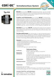
<strong>Schnellanschluss</strong>-System KA | <strong>Quick</strong> <strong>Connector</strong> System KA<br />
Einsatz<br />
Das innomatec<br />
<strong>Schnellanschluss</strong>-System<br />
Typ KA verschließt Rohre, Stutzen, Schläuche und alle<br />
Arten zylindrischer Körper oder verbindet sie mit dem<br />
gewünschten Leitungssystem. Ovale, raue und gegossene<br />
Flächen sowie Prüflinge mit großen Toleranzen<br />
werden radial abgedichtet.<br />
®<br />
Funktion und Arbeitsweise<br />
Das <strong>Schnellanschluss</strong>-System Typ KA kann manuell<br />
oder mit einem automatischen Werkzeug auf den Prüfling<br />
aufgesteckt/aufgefahren werden. Der <strong>Schnellanschluss</strong><br />
wird mit Steuerluft pneumatisch aktiviert.<br />
Die Abdichtung erfolgt durch einen elastischen Dichtgummi.<br />
Über den Prüfanschluss wird das System<br />
gefüllt oder verschlossen. Nach abgeschlossener<br />
Prüfung wird der Steueranschluss entlüftet, der Dichtring<br />
entspannt und der Anschluss kann entnommen/<br />
weggefahren werden. Je nach Durchmesser, Arbeitsdruck<br />
oder Beschaffenheit der Oberfläche (ölig usw.)<br />
muss der Anschluss gegen „Abrutschen“ gesichert<br />
werden (Gleitsperre, Vorrichtung).<br />
Zubehör<br />
Als Zubehör können wir liefern:<br />
• montierte Verschraubungen für Anschlussleitungen<br />
• montierte Handschiebeventile für Steuerluft<br />
• Absperrventile für Arbeitsmedium<br />
• Blindstopfen für Arbeitsmedium<br />
• Schwimmende Lagerung für maschinellen Einsatz<br />
Technische Daten<br />
Ausführung Standard: Aluminium, eloxiert<br />
Steuerdruck: 4,0 bar bis 8,0 bar<br />
Arbeitsdruck: -1,0 bar bis 8,0 bar<br />
Arbeitsmedium: Druckluft, Spurgase, Wasser<br />
Abdichtdurchmesser: 1,0 mm bis 150,0 mm<br />
Der Dichtgummi kann Durchmesserunterschiede von<br />
2,0 mm bis 3,0 mm aufnehmen (durchmesser abhängig).<br />
Temperaturbereich: -10 °C bis 70 °C<br />
Sonderausführungen für spezielle Einsatzfälle (z.B.<br />
hoher Druck, hohe/niedrige Temperatur, Größe des<br />
Abdichtdurchmessers) auf Anfrage.<br />
Application<br />
The innomatec<br />
<strong>Quick</strong> <strong>Connector</strong> System<br />
Type KA closes pipes, nozzles, tubes, and all types of<br />
cylindrical bodies or connects them to a desired line<br />
system. The radial sealing enables the adaption to<br />
oval, rough, cast surfaces as well as test specimen with<br />
large tolerances.<br />
®<br />
How to operate<br />
The type KA <strong>Quick</strong> <strong>Connector</strong> System can be plugged<br />
or driven onto the test specimen by hand or with<br />
an automatic tool. The <strong>Quick</strong> <strong>Connector</strong> System is<br />
pneumatically activated with control air. The sealing<br />
is carried out with an elastic rubber seal. The system<br />
is filled or closed by means of the test connection.<br />
Once the test has been completed, the pressure in<br />
the control connection is released, the sealing ring is<br />
relieved and the connection can be removed or moved<br />
away. According to diameter, operating pressure or<br />
condition of the surface (oily etc.) the quick connector<br />
has to be protected against sliding (sliding device,<br />
fixture).<br />
Accessories<br />
As accessories we can supply:<br />
• Mounted screwed connections for connecting<br />
pipelines<br />
• Mounted manual slide valve for control pressure<br />
• Shut-off valves for the operating medium<br />
• Blind plugs for the operating medium<br />
• Floating storage for uses with machines<br />
Technical data<br />
Finish Standard: Aluminium, anodized<br />
Control pressure: 4.0 to 8.0 bar<br />
Operating pressure: -1.0 to 8.0 bar<br />
Operating media: Compressed air, trace gas, water<br />
Seal diameter: 1.0 to 150.0 mm<br />
The rubber seal can cope with differences of between<br />
2.0 and 3.0 mm (depending on the diameter).<br />
Temperatures -10 to 70 °C<br />
Non standard versions for special cases of application<br />
(for example high pressure, high/low temperature,<br />
size of the sealing diameter) upon request.<br />
Standardversion KA<br />
Standard version KA<br />
KA-S mit Innendorn für Schläuche<br />
KA-S with innerbolt for tubes<br />
KA-S exzentrisch<br />
KA-S eccentric<br />
… und wenn’s mal komplizierter wird:<br />
… and if it gets more complicated:<br />
Nehmen Sie den einfachen<br />
Weg – kommen Sie zu uns!<br />
Take the easy<br />
way – come<br />
to us!<br />
8 <strong>Schnellanschluss</strong>-System KA | <strong>Quick</strong> <strong>Connector</strong> System KA
Mess- und <strong>Schnellanschluss</strong>-<strong>Systeme</strong><br />
Measurement and <strong>Quick</strong> <strong>Connector</strong> <strong>Systems</strong><br />
Seitenansicht/Halbschnitt | Side view/half-section<br />
M<br />
N<br />
O<br />
Typ KA | Type KA<br />
F<br />
Steueranschluss<br />
Control connection<br />
H<br />
A<br />
B<br />
D<br />
L<br />
Prüfanschluss<br />
Test connection<br />
K<br />
E<br />
R<br />
S<br />
T<br />
Befestigungsbohrungen (optional)<br />
Fixing holes<br />
(90°gedreht gezeichnet)<br />
(drawn turned thro’ 90°)<br />
Standard-Abmessung Typ KA | Standard dimensions, type KA<br />
Anschluss<br />
A B D E F H K L M N O R P<br />
Connection<br />
2 S T<br />
mm mm mm mm mm Gewinde<br />
Thread<br />
KA 03-05<br />
KA 05-07<br />
KA 07-09<br />
KA 09-11<br />
KA 11-13<br />
KA 13-15<br />
KA 15-17<br />
KA 17-19<br />
KA 19-21<br />
KA 20-22<br />
KA 22-24<br />
KA 24-26<br />
KA 26-28<br />
KA 28-30<br />
KA 30-32<br />
KA 32-34<br />
KA 34-36<br />
KA 36-38<br />
KA 38-41<br />
KA 41-44<br />
KA 44-47<br />
KA 47-50<br />
KA 50-53<br />
KA 53-56<br />
KA 56-59<br />
KA 59-62<br />
KA 62-65<br />
KA 65-69<br />
KA 69-73<br />
48<br />
48<br />
48<br />
48<br />
48<br />
48<br />
48<br />
48<br />
48<br />
70<br />
70<br />
70<br />
70<br />
70<br />
70<br />
70<br />
70<br />
70<br />
100<br />
100<br />
100<br />
100<br />
120<br />
120<br />
120<br />
120<br />
120<br />
120<br />
120<br />
30<br />
30<br />
30<br />
35<br />
35<br />
35<br />
40<br />
40<br />
40<br />
50<br />
50<br />
50<br />
56<br />
56<br />
56<br />
62<br />
62<br />
62<br />
70<br />
70<br />
70<br />
70<br />
81<br />
81<br />
81<br />
93<br />
93<br />
93<br />
93<br />
5<br />
7<br />
9<br />
11<br />
13<br />
15<br />
17<br />
19<br />
21<br />
22<br />
24<br />
26<br />
28<br />
30<br />
32<br />
34<br />
36<br />
38<br />
41<br />
44<br />
47<br />
50<br />
53<br />
56<br />
59<br />
62<br />
65<br />
69<br />
73<br />
12<br />
12<br />
12<br />
12<br />
12<br />
12<br />
12<br />
12<br />
12<br />
20<br />
20<br />
20<br />
20<br />
20<br />
20<br />
20<br />
20<br />
20<br />
30<br />
30<br />
30<br />
30<br />
30<br />
30<br />
30<br />
30<br />
30<br />
30<br />
30<br />
G 1/8"<br />
G 1/8"<br />
G 1/8"<br />
G 1/8"<br />
G 1/8"<br />
G 1/8"<br />
G 1/8"<br />
G 1/8"<br />
G 1/8"<br />
G 1/8"<br />
G 1/8"<br />
G 1/8"<br />
G 1/8"<br />
G 1/8"<br />
G 1/8"<br />
G 1/8"<br />
G 1/8"<br />
G 1/8"<br />
G 1/8"<br />
G 1/8"<br />
G 1/8"<br />
G 1/8"<br />
G 1/8"<br />
G 1/8"<br />
G 1/8"<br />
G 1/8"<br />
G 1/8"<br />
G 1/8"<br />
G 1/8"<br />
mm mm Gewinde<br />
Thread<br />
16<br />
16<br />
16<br />
16<br />
16<br />
16<br />
16<br />
16<br />
16<br />
23<br />
23<br />
23<br />
23<br />
23<br />
23<br />
23<br />
23<br />
23<br />
38<br />
38<br />
38<br />
38<br />
38<br />
38<br />
38<br />
38<br />
38<br />
38<br />
38<br />
3<br />
3<br />
3<br />
3<br />
3<br />
3<br />
3<br />
3<br />
3<br />
5<br />
5<br />
5<br />
5<br />
5<br />
5<br />
5<br />
5<br />
5<br />
5<br />
5<br />
5<br />
5<br />
5<br />
5<br />
5<br />
5<br />
5<br />
5<br />
5<br />
G 1/8"<br />
G 1/8"<br />
G 1/8"<br />
G 1/8"<br />
G 1/8"<br />
G 1/8"<br />
G 1/8"<br />
G 1/8"<br />
G 1/8"<br />
G 1/4"<br />
G 1/4"<br />
G 1/4"<br />
G 1/4"<br />
G 1/4"<br />
G 1/4"<br />
G 1/4"<br />
G 1/4"<br />
G 1/4"<br />
G 3/8"<br />
G 3/8"<br />
G 3/8"<br />
G 3/8"<br />
G 1/2"<br />
G 1/2"<br />
G 1/2"<br />
G 1/2"<br />
G 1/2"<br />
G 1/2"<br />
G 1/2"<br />
mm mm mm mm bar mm mm<br />
54<br />
54<br />
54<br />
54<br />
54<br />
54<br />
54<br />
54<br />
54<br />
77<br />
77<br />
77<br />
77<br />
77<br />
77<br />
77<br />
77<br />
77<br />
116<br />
116<br />
116<br />
116<br />
116<br />
116<br />
116<br />
116<br />
116<br />
116<br />
116<br />
8<br />
8<br />
8<br />
8<br />
8<br />
8<br />
8<br />
8<br />
8<br />
13<br />
13<br />
13<br />
13<br />
13<br />
13<br />
13<br />
13<br />
13<br />
31<br />
31<br />
31<br />
31<br />
31<br />
31<br />
31<br />
31<br />
31<br />
31<br />
31<br />
34<br />
34<br />
34<br />
34<br />
34<br />
34<br />
34<br />
34<br />
34<br />
49<br />
49<br />
49<br />
49<br />
49<br />
49<br />
49<br />
49<br />
49<br />
55<br />
55<br />
55<br />
55<br />
55<br />
55<br />
55<br />
55<br />
55<br />
55<br />
55<br />
10<br />
10<br />
10<br />
10<br />
10<br />
10<br />
10<br />
10<br />
10<br />
15<br />
15<br />
15<br />
15<br />
15<br />
15<br />
15<br />
15<br />
15<br />
15<br />
15<br />
15<br />
15<br />
15<br />
15<br />
15<br />
15<br />
15<br />
15<br />
15<br />
4<br />
4<br />
4<br />
3<br />
3<br />
3<br />
2<br />
2<br />
2<br />
4<br />
4<br />
4<br />
3<br />
3<br />
3<br />
2<br />
2<br />
2<br />
1<br />
1<br />
1<br />
1<br />
1<br />
1<br />
1<br />
1<br />
1<br />
1<br />
1<br />
M5<br />
M5<br />
M5<br />
M5<br />
M5<br />
M5<br />
M5<br />
M5<br />
M5<br />
M5<br />
M5<br />
M5<br />
M5<br />
M5<br />
M5<br />
M5<br />
M5<br />
M5<br />
M6<br />
M6<br />
M6<br />
M6<br />
M6<br />
M6<br />
M6<br />
M6<br />
M6<br />
M6<br />
M6<br />
4<br />
4<br />
4<br />
4<br />
4<br />
4<br />
4<br />
4<br />
4<br />
4<br />
4<br />
4<br />
4<br />
4<br />
4<br />
4<br />
4<br />
4<br />
6<br />
6<br />
6<br />
6<br />
6<br />
6<br />
6<br />
6<br />
6<br />
6<br />
6<br />
Diese Maßtabelle ist ein Auszug der häufig eingesetzten<br />
Typen.<br />
Der maximale Prüfdruck ist in der Spalte P 2 angegeben.<br />
Dieser gilt nur bei Idealbedingungen (Dichtfläche<br />
sauber, trocken, bearbeitet). Bei höheren Prüfdrücken<br />
oder feuchten/öligen Oberflächen muss der <strong>Schnellanschluss</strong><br />
gegen Abrutschen gesichert werden.<br />
This dimensional table is an excerpt of the most<br />
frequently used types.<br />
The maximum test pressure can be found in column<br />
P 2 . This is only valid for ideal conditions (sealing surface<br />
clean, dry and processed). For higher test pressures<br />
or damp/oily surfaces, the quick connector must<br />
be secured against slipping.<br />
<strong>Schnellanschluss</strong>-System KA | <strong>Quick</strong> <strong>Connector</strong> System KA<br />
9
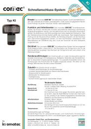
<strong>Schnellanschluss</strong>-System KI | <strong>Quick</strong> <strong>Connector</strong> System KI<br />
Einsatz<br />
Das innomatec<br />
<strong>Schnellanschluss</strong>-System<br />
Typ KI verschließt Bohrungen oder verbindet sie mit<br />
einem Leitungssystem. Ovale, raue und gegossene<br />
Flächen sowie Prüflinge mit großen Toleranzen werden<br />
radial abgedichtet.<br />
®<br />
Funktion und Arbeitsweise<br />
Das <strong>Schnellanschluss</strong>-System Typ KI kann manuell<br />
oder mit einem automatischen Werkzeug in die Bohrung<br />
eingesteckt/eingefahren werden. Der <strong>Schnellanschluss</strong><br />
wird mit Steuerluft pneumatisch aktiviert. Die<br />
Abdichtung in der Bohrung erfolgt durch einen elastischen<br />
Dichtgummi. Über den Arbeitsanschluss wird<br />
das System gefüllt oder verschlossen. Nach abgeschlossener<br />
Prüfung wird der Steueranschluss entlüftet,<br />
der Dichtring entspannt und der Anschluss kann<br />
entnommen/weggefahren werden. Je nach Durchmesser,<br />
Arbeitsdruck oder Beschaffenheit der Oberfläche<br />
(ölig usw.) muss der Anschluss gegen „Abrutschen“<br />
gesichert werden (Gleitsperre, Vorrichtung).<br />
Zubehör<br />
Als Zubehör können wir liefern:<br />
• montierte Verschraubungen für Anschlussleitungen<br />
• montierte Handschiebeventile für Steuerluft<br />
• Absperrventile für Arbeitsmedium<br />
• Blindstopfen für Arbeitsmedium<br />
• Schwimmende Lagerung für maschinellen Einsatz<br />
Technische Daten<br />
Ausführung Standard: Aluminium, eloxiert<br />
Steuerdruck: 4,0 bar bis 8,0 bar<br />
Arbeitsdruck: -1,0 bar bis 8,0 bar<br />
Arbeitsmedium: Druckluft, Spurgase, Wasser<br />
Abdichtdurchmesser: 10,0 mm bis 150,0 mm<br />
Der Dichtgummi kann Durchmesserunterschiede von<br />
2,0 mm bis 3,0 mm aufnehmen (durchmesserabhängig).<br />
Temperaturbereich: -10 °C bis 70 °C<br />
Sonderausführungen für spezielle Einsatzfälle (z.B.<br />
hoher Druck, hohe/niedrige Temperatur, Größe des<br />
Abdichtdurchmessers) auf Anfrage.<br />
Application<br />
The innomatec<br />
<strong>Quick</strong> <strong>Connector</strong> System<br />
Typ KI closes drill holes or connects them with a line<br />
system. The radial sealing enables the adaption to oval,<br />
rough, cast surfaces as well as test specimen with<br />
large tolerances.<br />
®<br />
How to operate<br />
The type KI <strong>Quick</strong> <strong>Connector</strong> System can be plugged<br />
or driven into the hole by hand or with an automatic<br />
tool. The <strong>Quick</strong> <strong>Connector</strong> System is pneumatically<br />
activated with control air. The seal within the hole is<br />
achieved by means of an elastic rubber seal. The system<br />
is then filled or closed via the operating connection.<br />
Once the test has been completed the pressure<br />
in the control connection is released, the sealing ring is<br />
relieved and the connection can be removed or moved<br />
away. According to diameter, operating pressure or<br />
condition of the surface (oily etc.) the quick connector<br />
has to be protected against sliding (sliding device,<br />
fixture).<br />
Accessories<br />
As accessories we can supply:<br />
• Mounted screwed connections for connecting<br />
pipelines<br />
• Mounted manual slide valve for control pressure<br />
• Shut-off valves for the operating medium<br />
• Blind plugs for the operating medium<br />
• Floating storage for uses with machines<br />
Technical data<br />
Finish Standard: Aluminium, anodized<br />
Control pressure: 4.0 to 8.0 bar<br />
Operating pressure: -1.0 to 8.0 bar<br />
Operating media: Compressed air, trace gas, water<br />
Seal diameter: 10.0 to 150.0 mm<br />
The rubber seal can cope with differences of between<br />
2.0 and 3.0 mm (depending on the diameter).<br />
Temperatures: -10 to 70 °C<br />
Non standard versions for special cases of application<br />
(for example high pressure, high/low temperature,<br />
size of the sealing diameter) upon request.<br />
Standardversion KI<br />
Standard version KI<br />
KI-S aus Edelstahl<br />
KI-S made of high-grade steel<br />
KI-S mit Drucktaster-Betätigung<br />
KI-S with push button-actuation<br />
… und wenn’s mal komplizierter wird:<br />
… and if it gets more complicated:<br />
Nehmen Sie den einfachen<br />
Weg – kommen Sie zu uns!<br />
Take the easy<br />
way – come<br />
to us!<br />
10 <strong>Schnellanschluss</strong>-System KI | <strong>Quick</strong> <strong>Connector</strong> System KI
Mess- und <strong>Schnellanschluss</strong>-<strong>Systeme</strong><br />
Measurement and <strong>Quick</strong> <strong>Connector</strong> <strong>Systems</strong><br />
Seitenansicht/Halbschnitt | Side view/half-section<br />
Typ KI | Type KI<br />
E<br />
C<br />
G<br />
D<br />
T<br />
S<br />
Befestigungsbohrungen (optional)<br />
Fixing holes (optional)<br />
(90°gedreht gezeichnet)<br />
(drawn turned thro’ 90°)<br />
F<br />
Steueranschluss<br />
Control connection<br />
B<br />
A<br />
H<br />
Prüfanschluss<br />
Text connection<br />
Standard-Abmessung Typ KI | Standard dimensions, type KI<br />
Anschluss<br />
A B C D E F G H P<br />
Connection<br />
2 S T<br />
mm mm mm mm mm mm<br />
KI 10-12<br />
KI 12-14<br />
KI 14-16<br />
KI 16-18<br />
KI 18-20<br />
KI 20-22<br />
KI 22-24<br />
KI 24-26<br />
KI 26-28<br />
KI 28-30<br />
KI 30-32<br />
KI 32-34<br />
KI 34-37<br />
KI 37-40<br />
KI 40-43<br />
KI 43-47<br />
KI 47-51<br />
KI 51-55<br />
KI 55-58<br />
KI 58-62<br />
KI 62-65<br />
KI 65-69<br />
KI 69-72<br />
KI 72-75<br />
10<br />
12<br />
14<br />
16<br />
18<br />
20<br />
22<br />
24<br />
26<br />
28<br />
30<br />
32<br />
34<br />
37<br />
40<br />
43<br />
47<br />
51<br />
55<br />
58<br />
62<br />
65<br />
69<br />
72<br />
40<br />
40<br />
40<br />
40<br />
40<br />
40<br />
50<br />
50<br />
50<br />
60<br />
60<br />
60<br />
75<br />
75<br />
75<br />
90<br />
90<br />
90<br />
100<br />
100<br />
100<br />
110<br />
110<br />
110<br />
5<br />
5<br />
5<br />
6<br />
6<br />
6<br />
8<br />
8<br />
8<br />
12<br />
12<br />
12<br />
12<br />
12<br />
12<br />
12<br />
12<br />
12<br />
12<br />
12<br />
12<br />
12<br />
12<br />
12<br />
10<br />
10<br />
10<br />
10<br />
10<br />
10<br />
12<br />
12<br />
12<br />
20<br />
20<br />
20<br />
30<br />
30<br />
30<br />
30<br />
30<br />
30<br />
30<br />
30<br />
30<br />
30<br />
30<br />
30<br />
59<br />
59<br />
59<br />
62<br />
62<br />
62<br />
54<br />
54<br />
54<br />
66<br />
66<br />
66<br />
82<br />
82<br />
82<br />
82<br />
82<br />
82<br />
82<br />
82<br />
82<br />
82<br />
82<br />
82<br />
Gewinde<br />
Thread<br />
M5<br />
M5<br />
M5<br />
M5<br />
M5<br />
M5<br />
G 1/8"<br />
G 1/8"<br />
G 1/8"<br />
G 1/8"<br />
G 1/8"<br />
G 1/8"<br />
G 1/8"<br />
G 1/8"<br />
G 1/8"<br />
G 1/8"<br />
G 1/8"<br />
G 1/8"<br />
G 1/8"<br />
G 1/8"<br />
G 1/8"<br />
G 1/8"<br />
G 1/8"<br />
G 1/8"<br />
mm<br />
20<br />
20<br />
20<br />
21<br />
21<br />
21<br />
25<br />
25<br />
25<br />
37<br />
37<br />
37<br />
47<br />
47<br />
47<br />
47<br />
47<br />
47<br />
47<br />
47<br />
47<br />
47<br />
47<br />
47<br />
Gewinde<br />
Thread<br />
G 1/8"<br />
G 1/8"<br />
G 1/8"<br />
G 1/8"<br />
G 1/8"<br />
G 1/8"<br />
G 1/8"<br />
G 1/8"<br />
G 1/8"<br />
G 1/8"<br />
G 1/8"<br />
G 1/8"<br />
G 3/8"<br />
G 3/8"<br />
G 3/8"<br />
G 1/2"<br />
G 1/2"<br />
G 1/2"<br />
G 1/2"<br />
G 1/2"<br />
G 1/2"<br />
G 1/2"<br />
G 1/2"<br />
G 1/2"<br />
bar mm mm<br />
5<br />
5<br />
5<br />
5<br />
5<br />
5<br />
5<br />
5<br />
5<br />
5<br />
5<br />
5<br />
1<br />
1<br />
1<br />
1<br />
1<br />
1<br />
1<br />
1<br />
1<br />
1<br />
1<br />
1<br />
M5<br />
M5<br />
M5<br />
M5<br />
M5<br />
M5<br />
M5<br />
M5<br />
M5<br />
M5<br />
M5<br />
M5<br />
M5<br />
M5<br />
M5<br />
M6<br />
M6<br />
M6<br />
M6<br />
M6<br />
M6<br />
M6<br />
M6<br />
M6<br />
4,5<br />
4,5<br />
4,5<br />
4,5<br />
4,5<br />
4,5<br />
4,5<br />
4,5<br />
4,5<br />
4,5<br />
4,5<br />
4,5<br />
4,5<br />
4,5<br />
4,5<br />
4,5<br />
4,5<br />
4,5<br />
4,5<br />
4,5<br />
4,5<br />
4,5<br />
4,5<br />
4,5<br />
Diese Maßtabelle ist ein Auszug der häufig eingesetzten<br />
Typen.<br />
Der maximale Prüfdruck ist in der Spalte P 2 angegeben.<br />
Dieser gilt nur bei Idealbedingungen (Dichtfläche<br />
sauber, trocken, bearbeitet). Bei höheren Prüfdrücken<br />
oder feuchten/öligen Oberflächen muss der <strong>Schnellanschluss</strong><br />
gegen Abrutschen gesichert werden.<br />
This dimensional table is an excerpt of the most<br />
frequently used types.<br />
The maximum test pressure can be found in column<br />
P 2 . This is only valid for ideal conditions (sealing surface<br />
clean, dry and processed). For higher test pressures<br />
or damp/oily surfaces, the quick connector must<br />
be secured against slipping.<br />
<strong>Schnellanschluss</strong>-System KI | <strong>Quick</strong> <strong>Connector</strong> System KI<br />
11
<strong>Schnellanschluss</strong>-System KA-M | <strong>Quick</strong> <strong>Connector</strong> System KA-M<br />
Einsatz<br />
Das innomatec<br />
KA-M verschließt Rohre, Stutzen, Schläuche und alle<br />
Arten zylindrischer Körper oder verbindet sie mit dem<br />
gewünschten Leitungssystem. Die Adaption an ovalen,<br />
rauen, gegossenen Flächen sowie an Prüflingen mit<br />
großen Toleranzen wird durch die radiale Abdichtung<br />
ermöglicht.<br />
®<br />
<strong>Schnellanschluss</strong>-System Typ<br />
Funktion und Arbeitsweise<br />
Das <strong>Schnellanschluss</strong>-System Typ KA-M wird manuell<br />
auf den Prüfling aufgesteckt. Durch Betätigen des<br />
Kniehebels wird der <strong>Schnellanschluss</strong> gespannt.<br />
Die Abdichtung erfolgt durch einen elastischen Dichtgummi.<br />
Über den Prüfanschluss wird das System<br />
gefüllt oder verschlossen. Nach abgeschlossener<br />
Prüfung wird der <strong>Schnellanschluss</strong> über den Kniehebel<br />
entspannt und kann entnommen werden.<br />
Je nach Durchmesser, Arbeitsdruck oder Beschaffenheit<br />
der Oberfläche (ölig usw.) muss der Anschluss<br />
gegen „Abrutschen“ gesichert werden (Gleitsperre,<br />
Vorrichtung).<br />
Zubehör<br />
Als Zubehör können wir liefern:<br />
•montierte Verschraubungen für Anschlussleitungen<br />
• Absperrventile für Arbeitsmedium<br />
• Blindstopfen für Arbeitsmedium<br />
Technische Daten<br />
Ausführung Standard: Aluminium eloxiert, rostfreier<br />
Stahl<br />
Arbeitsdruck: -1,0 bar bis 8,0 bar<br />
Arbeitsmedium: Druckluft, Spurgas, Wasser<br />
Abdichtdurchmesser: 1,0 mm bis 80,0 mm<br />
Der Dichtgummi kann Durchmesserunterschiede von<br />
2,0 mm bis 3,0 mm aufnehmen (durchmesserabhängig).<br />
Temperaturbereich: -10 °C bis 70 °C<br />
Sonderausführungen für spezielle Einsatzfälle (z.B.<br />
hoher Druck, hohe/niedrige Temperatur, Größe des<br />
Abdichtdurchmessers) auf Anfrage.<br />
Application<br />
The innomatec<br />
<strong>Quick</strong> <strong>Connector</strong> System<br />
Type KA-M closes pipes, nozzles, tubes, and all types<br />
of cylindrical bodies or connect them to a desired line<br />
system. The radial sealing enables the adaption to oval,<br />
rough, cast surfaces as well as test specimen with<br />
large tolerances.<br />
®<br />
How to operate<br />
The type KA-M <strong>Quick</strong> <strong>Connector</strong> System is placed<br />
manually on the test specimen. By pressing the kneelever<br />
the quick connector is clamped. The sealing is<br />
carried out with an elastic rubber seal. The system is<br />
filled or closed by means of the test connection. Once<br />
the test has been completed, the quick connector has<br />
to release over the knee-lever and can be removed.<br />
According to diameter, operating pressure or condition<br />
of the surface (oily etc.) the quick connector has to be<br />
protected against sliding (sliding device, fixture).<br />
Accessories<br />
As accessories we can supply:<br />
• Mounted screwed connections for connecting<br />
pipelines<br />
• Block valves for the operating medium<br />
• Blind plugs for the operating medium<br />
Technical data<br />
Finish Standard: Aluminium, anodized, stainless steel<br />
Operating pressure: -1.0 to 8.0 bar<br />
Operating media: Compressed air, tracegas, water<br />
Seal diameter: 1.0 to 80.0 mm<br />
The rubber seal can cope with differences of between<br />
2.0 and 3.0 mm (depending on the diameter).<br />
Temperatures -10 to 70 °C<br />
Non standard versions for special cases of application<br />
(for example high pressure, high/low temperature,<br />
size of the sealing diameter) upon request.<br />
Standardversion KA-M<br />
Standard version KA-M<br />
KA-M-S-GL Hochdruck für Glattrohre<br />
KA-M-S-GL High pressure for plain tubes<br />
KA-M-S mit Doppelabdichtung<br />
KA-M-S with double sealing<br />
… und wenn’s mal komplizierter wird:<br />
… and if it gets more complicated:<br />
Nehmen Sie den einfachen<br />
Weg – kommen Sie zu uns!<br />
Take the easy<br />
way – come<br />
to us!<br />
12 <strong>Schnellanschluss</strong>-System KA-M | <strong>Quick</strong> <strong>Connector</strong> System KA-M
Mess- und <strong>Schnellanschluss</strong>-<strong>Systeme</strong><br />
Measurement and <strong>Quick</strong> <strong>Connector</strong> <strong>Systems</strong><br />
Seitenansicht/Halbschnitt | Side view/half-section<br />
Typ KA-M | Type KA-M<br />
Standard-Abmessung Typ KA-M | Standard dimensions, type KA-M<br />
Anschluss<br />
Connection<br />
A B C D E F G H I K L P 2<br />
mm mm mm mm mm mm mm Gewinde<br />
Thread<br />
mm mm mm mm<br />
KA-M 03-05 5 30 50 78 8 ca. 40 75 G 1/8" 37 3 12 4<br />
KA-M 05-07 7 30 50 78 8 ca. 40 75 G 1/8" 37 3 12 4<br />
KA-M 07-09 9 30 50 78 8 ca. 40 75 G 1/8" 37 3 12 4<br />
KA-M 09-11 11 35 50 78 8 ca. 40 75 G 1/8" 37 3 12 3<br />
KA-M 11-13 13 35 50 78 8 ca. 40 75 G 1/8" 37 3 12 3<br />
KA-M 13-15 15 35 50 78 8 ca. 40 75 G 1/8" 37 3 12 3<br />
KA-M 15-17 17 40 50 78 8 ca. 40 75 G 1/8" 37 3 12 2<br />
KA-M 17-19 19 40 50 78 8 ca. 40 75 G 1/8" 37 3 12 2<br />
KA-M 19-21 21 40 50 78 8 ca. 40 75 G 1/8" 37 3 12 2<br />
KA-M 20-22 22 42 75 108 13 ca. 60 120 G 1/4" 50 4 20 4<br />
KA-M 22-24 24 42 75 108 13 ca. 60 120 G 1/4" 50 4 20 4<br />
KA-M 24-26 26 42 75 108 13 ca. 60 120 G 1/4" 50 4 20 4<br />
KA-M 26-28 28 48 75 108 13 ca. 60 120 G 1/4" 50 4 20 3<br />
KA-M 28-30 30 48 75 108 13 ca. 60 120 G 1/4" 50 4 20 3<br />
KA-M 30-32 32 48 75 108 13 ca. 60 120 G 1/4" 50 4 20 3<br />
KA-M 32-34 34 54 75 108 13 ca. 60 120 G 1/4" 50 4 20 2<br />
KA-M 34-36 36 54 75 108 13 ca. 60 120 G 1/4" 50 4 20 2<br />
KA-M 36-38 38 54 75 108 13 ca. 60 120 G 1/4" 50 4 20 2<br />
Diese Maßtabelle ist ein Auszug der häufig eingesetzten<br />
Typen.<br />
Der maximale Prüfdruck ist in der Spalte P 2 angegeben.<br />
Dieser gilt nur bei Idealbedingungen (Dichtfläche<br />
sauber, trocken, bearbeitet). Bei höheren Prüfdrücken<br />
oder feuchten/öligen Oberflächen muss der <strong>Schnellanschluss</strong><br />
gegen Abrutschen gesichert werden.<br />
This dimensional table is an excerpt of the most<br />
frequently used types.<br />
The maximum test pressure can be found in column<br />
P 2 . This is only valid for ideal conditions (sealing surface<br />
clean, dry and processed). For higher test pressures<br />
or damp/oily surfaces, the quick connector must<br />
be secured against slipping.<br />
<strong>Schnellanschluss</strong>-System KA-M | <strong>Quick</strong> <strong>Connector</strong> System KA-M<br />
13
<strong>Schnellanschluss</strong>-System KI-M | <strong>Quick</strong> <strong>Connector</strong> System KI-M<br />
Einsatz<br />
Das innomatec<br />
<strong>Schnellanschluss</strong>-System<br />
Typ KI-M verschließt Bohrungen oder verbindet sie mit<br />
einem Leitungssystem. Die Adaption an ovalen,<br />
rauen, gegossenen Flächen sowie an Prüflingen mit<br />
großen Toleranzen wird durch die radiale Abdichtung<br />
ermöglicht.<br />
®<br />
Funktion und Arbeitsweise<br />
Das <strong>Schnellanschluss</strong>-System Typ KI-M wird manuell<br />
in den Prüfling eingesteckt. Durch Betätigen des<br />
Kniehebels wird der <strong>Schnellanschluss</strong> gespannt. Die<br />
Abdichtung in der Bohrung erfolgt durch einen elastischen<br />
Dichtgummi. Über den Prüfanschluss wird das<br />
System gefüllt oder verschlossen. Nach abgeschlossener<br />
Prüfung wird der <strong>Schnellanschluss</strong> über<br />
den Kniehebel entspannt und kann entnommen werden.<br />
Je nach Durchmesser, Arbeitsdruck oder Beschaffenheit<br />
der Oberfläche (ölig usw.) muss der Anschluss<br />
gegen „Abrutschen“ gesichert werden (Gleitsperre,<br />
Vorrichtung).<br />
Zubehör<br />
Als Zubehör können wir liefern:<br />
• montierte Verschraubungen für Anschlussleitungen<br />
• Absperrventile für Arbeitsmedium<br />
• Blindstopfen für Arbeitsmedium<br />
Technische Daten<br />
Ausführung Standard: Aluminium, eloxiert,<br />
rostfreier Stahl<br />
Arbeitsdruck: -1,0 bar bis 8,0 bar<br />
Arbeitsmedium: Druckluft, Spurgas, Wasser<br />
Abdichtdurchmesser: 10,0 mm bis 80,0 mm<br />
Der Dichtgummi kann Durchmesserunterschiede von<br />
2,0 mm bis 3,0 mm aufnehmen (durchmesserabhängig).<br />
Temperaturbereich: -10 °C bis 70 °C<br />
Sonderausführungen für spezielle Einsatzfälle (z.B.<br />
hoher Druck, hohe/niedrige Temperatur, Größe des<br />
Abdichtdurchmessers) auf Anfrage.<br />
Application<br />
The innomatec<br />
<strong>Quick</strong> <strong>Connector</strong> System<br />
Type KI-M closes drill holes or connects them with a<br />
line system. The radial sealing enables the adaption to<br />
oval, rough, cast surfaces as well as test specimen with<br />
large tolerances.<br />
®<br />
How to operate<br />
The type KI-M <strong>Quick</strong> <strong>Connector</strong> System is placed<br />
manually in the test specimen. By pressing the kneelever<br />
the quick connector is clamped. The seal within<br />
the hole is achieved by means of an elastic rubber<br />
seal. The system is filled or closed by means of the<br />
test connection. Once the test has been completed,<br />
the quick connector has to release over the knee-lever<br />
and can be removed. According to diameter, operating<br />
pressure or quality of the surface (oily etc.) the quick<br />
connector has to be protected against sliding (sliding<br />
device, device).<br />
Accessories<br />
As accessories we can supply:<br />
• Mounted screwed connections for connecting<br />
pipelines<br />
• Block valves for the operating medium<br />
• Blind plugs for the operating medium<br />
Technical data<br />
Finish Standard: Aluminium, anodized, stainless steel<br />
Operating pressure: -1.0 to 8.0 bar<br />
Operating media: Compressed air, tracegas, water<br />
Seal diameter: 10.0 to 80.0 mm<br />
The rubber seal can cope with differences of between<br />
2.0 and 3.0 mm (depending on the diameter).<br />
Temperatures -10 to 70 °C<br />
Non standard versions for special cases of application<br />
(for example high pressure, high/low temperature,<br />
size of the sealing diameter) upon request.<br />
Standardversion KI-M<br />
Standard version KI-M<br />
KI-M-S für große Durchmesser<br />
KI-M-S for big diameters<br />
KI-M-S mit Gleitsperre<br />
KI-M-S with sliding device<br />
… und wenn’s mal komplizierter wird:<br />
… and if it gets more complicated:<br />
Nehmen Sie den einfachen<br />
Weg – kommen Sie zu uns!<br />
Take the easy<br />
way – come<br />
to us!<br />
14 <strong>Schnellanschluss</strong>-System KI-M | <strong>Quick</strong> <strong>Connector</strong> System KI-M
Mess- und <strong>Schnellanschluss</strong>-<strong>Systeme</strong><br />
Measurement and <strong>Quick</strong> <strong>Connector</strong> <strong>Systems</strong><br />
Seitenansicht/Halbschnitt | Side view/half-section<br />
Typ KI-M | Type KI-M<br />
Standard-Abmessung Typ KI-M | Standard dimensions, type KI-M<br />
Anschluss<br />
Connection<br />
A B C D E F G H I J P 2<br />
mm mm mm mm mm mm mm mm mm Gewinde<br />
Thread<br />
KI-M 10-12 10 35 25 10 10 75 ca. 50 75 33 G 1/8" 5<br />
KI-M 12-14 12 35 25 10 10 75 ca. 50 75 33 G 1/8" 5<br />
KI-M 14-16 14 35 25 10 10 75 ca. 50 75 33 G 1/8" 5<br />
KI-M 16-18 16 35 28 10 13 78 ca. 50 75 33 G 1/8" 5<br />
KI-M 18-20 18 35 28 10 13 78 ca. 50 75 33 G 1/8" 5<br />
KI-M 20-22 20 35 28 10 13 78 ca. 50 75 33 G 1/8" 5<br />
KI-M 22-24 22 35 32 12 15 82 ca. 50 75 33 G 1/8" 5<br />
KI-M 24-26 24 35 32 12 15 82 ca. 50 75 33 G 1/8" 5<br />
KI-M 26-28 26 35 32 12 15 82 ca. 50 75 33 G 1/8" 5<br />
KI-M 28-31 28 50 55 30 20 118 ca. 80 120 40 G 1/8" 1<br />
KI-M 31-34 31 50 55 30 20 118 ca. 80 120 40 G 1/8" 1<br />
KI-M 34-37 34 50 55 30 20 118 ca. 80 120 40 G 1/8" 1<br />
KI-M 37-40 37 50 55 30 20 118 ca. 80 120 40 G 1/8" 1<br />
KI-M 40-43 40 50 55 30 20 118 ca. 80 120 40 G 1/8" 1<br />
KI-M 43-47 43 50 55 30 20 118 ca. 80 120 40 G 1/8" 1<br />
KI-M 47-51 47 60 58 30 23 121 ca. 80 120 40 G 1/8" 1<br />
KI-M 51-55 51 60 58 30 23 121 ca. 80 120 40 G 1/8" 1<br />
bar<br />
Diese Maßtabelle ist ein Auszug der häufig eingesetzten<br />
Typen.<br />
Der maximale Prüfdruck ist in der Spalte P 2 angegeben.<br />
Dieser gilt nur bei Idealbedingungen (Dichtfläche<br />
sauber, trocken, bearbeitet). Bei höheren Prüfdrücken<br />
oder feuchten/öligen Oberflächen muss der <strong>Schnellanschluss</strong><br />
gegen Abrutschen gesichert werden.<br />
This dimensional table is an excerpt of the most<br />
frequently used types.<br />
The maximum test pressure can be found in column<br />
P 2 . This is only valid for ideal conditions (sealing surface<br />
clean, dry and processed). For higher test pressures<br />
or damp/oily surfaces, the quick connector must<br />
be secured against slipping.<br />
<strong>Schnellanschluss</strong>-System KI-M | <strong>Quick</strong> <strong>Connector</strong> System KI-M<br />
15
<strong>Schnellanschluss</strong>-System GWA | <strong>Quick</strong> <strong>Connector</strong> System GWA<br />
Einsatz<br />
Das innomatec<br />
<strong>Schnellanschluss</strong>-System<br />
Typ GWA verschließt Außengewinde oder verbindet sie<br />
mit einem Leitungssystem. Die Prüflingsbohrung wird<br />
axial abgedichtet.<br />
®<br />
Funktion und Arbeitsweise<br />
Das <strong>Schnellanschluss</strong>-System Typ GWA wird einfach<br />
handfest auf den Anschluss des Prüflings geschraubt<br />
bis die Dichtung am Gegenstück anliegt. Der <strong>Schnellanschluss</strong><br />
gewährleistet eine druckdichte Verbindung<br />
bis 340 bar, wenn das System mit Druck beaufschlagt<br />
wird. Die Prüfung kann nun durch Zuführen des Druckmediums<br />
erfolgen. Nach erfolgter Prüfung den Prüfdruck<br />
entspannen. Der <strong>Schnellanschluss</strong> lässt sich<br />
ohne Werkzeug von Hand wieder abschrauben.<br />
Zubehör<br />
Als Zubehör können wir liefern:<br />
• montierte Verschraubungen für Anschlussleitungen<br />
• Absperrventile für Arbeitsmedium<br />
• Blindstopfen für Arbeitsmedium<br />
Technische Daten<br />
Ausführung Standard: rostfreier Stahl<br />
Arbeitsdruck: -1,0 bar bis 340 bar<br />
Arbeitsmedium: Druckluft, Spurgas, Wasser<br />
Temperaturbereich: -10 °C bis 70 °C<br />
Andere Temperaturen auf Anfrage<br />
Application<br />
The innomatec type GWA <strong>Quick</strong> <strong>Connector</strong><br />
System connects external threads or links them to a<br />
pipeline system. The sample bore is sealed axially.<br />
How to operate<br />
The type GWA <strong>Quick</strong> <strong>Connector</strong> System is simply<br />
screwed onto the test specimen connection until it<br />
is hand-tight so that the seal is in contact with the<br />
counterpart. The <strong>Quick</strong> <strong>Connector</strong> System guarantees<br />
a pressure-tight connection up to 340 bar when pressure<br />
is applied to the system. The test can then be<br />
carried out by feeding the pressure medium. After the<br />
test has been completed the test pressure is reduced<br />
and the <strong>Quick</strong> <strong>Connector</strong> System can be unscrewed<br />
again by hand without tools.<br />
Accessories<br />
As accessories we can supply:<br />
• Ready-assembled screwed connections for<br />
connecting pipelines<br />
• Shut-off valves for the operating medium<br />
• Blind plugs for the operating medium<br />
Technical data<br />
Finish Standard: Stainless steel<br />
Operating pressure: -1.0 bar to 340 bar<br />
Operating media: Compressed air, trace gas, water<br />
Temperatures: -10 to 70 °C<br />
Other temperatures upon request<br />
®<br />
Abdichtung zum Prüfling<br />
Seal to the specimen<br />
beweglicher Kolben<br />
Movable piston<br />
Kolbenabdichtung<br />
Piston-seal<br />
Prüfling<br />
Specimen<br />
Prüfmedium<br />
bis 340 bar<br />
Test medium<br />
until 340 bar<br />
Standardversion GWA<br />
Standard version GWA<br />
GWA-S verlängert<br />
GWA-S lengthened<br />
GWA-S kurze Bauform / Stopfen<br />
GWA-S short design / Plug<br />
… und wenn’s mal komplizierter wird:<br />
… and if it gets more complicated:<br />
Nehmen Sie den einfachen<br />
Weg – kommen Sie zu uns!<br />
Take the easy<br />
way – come<br />
to us!<br />
16 <strong>Schnellanschluss</strong>-System GWA | <strong>Quick</strong> <strong>Connector</strong> System GWA
Mess- und <strong>Schnellanschluss</strong>-<strong>Systeme</strong><br />
Measurement and <strong>Quick</strong> <strong>Connector</strong> <strong>Systems</strong><br />
C2<br />
Seitenansicht/Halbschnitt<br />
(mit Arbeitsanschluss)<br />
Side view/half section<br />
(with operating connection)<br />
Typ GWA | Type GWA<br />
B<br />
A<br />
B<br />
A<br />
E<br />
C1<br />
Seitenansicht/Halbschnitt<br />
(ohne Arbeitsanschluss)<br />
Side view/half section<br />
(without operating connection)<br />
Standard-Abmessung Typ GWA | Standard dimensions, type GWA<br />
Anschlussgewinde A für<br />
B C<br />
<strong>Connector</strong> thread A for<br />
1 C 2 E<br />
metrische Außengewinde<br />
metric external threads<br />
M 10 x 1,0<br />
M 12 x 1,5<br />
M 14 x 1,5<br />
M 16 x 1,5<br />
M 18 x 1,5<br />
M 20 x 1,5<br />
M 22 x 1,5<br />
M 24 x 1,5<br />
M 26 x 1,5<br />
G Außengewinde<br />
G external threads<br />
G 1/8"<br />
G 1/4"<br />
G 3/8"<br />
G 1/2"<br />
G 3/4"<br />
G 1"<br />
G Außengewinde<br />
G external threads<br />
G 1/8"<br />
G 1/4"<br />
G 3/8"<br />
G 1/2"<br />
G 3/4"<br />
G 1"<br />
mm mm mm<br />
22,0<br />
27,0<br />
27,0<br />
32,0<br />
35,0<br />
37,0<br />
37,0<br />
44,0<br />
44,0<br />
26,0<br />
27,0<br />
27,0<br />
28,0<br />
28,0<br />
33,0<br />
33,0<br />
56,0<br />
56,0<br />
36,0<br />
41,0<br />
41,0<br />
38,0<br />
38,0<br />
51,0<br />
51,0<br />
52,0<br />
52,0<br />
mm mm mm<br />
22,0<br />
27,0<br />
32,0<br />
37,0<br />
44,0<br />
52,0<br />
26,0<br />
27,0<br />
28,0<br />
33,0<br />
33,0<br />
40,0<br />
36,0<br />
41,0<br />
38,0<br />
51,0<br />
52,0<br />
60,0<br />
mm mm mm<br />
22,0<br />
27,0<br />
32,0<br />
37,0<br />
44,0<br />
52,0<br />
26,0<br />
27,0<br />
28,0<br />
33,0<br />
33,0<br />
40,0<br />
36,0<br />
41,0<br />
38,0<br />
51,0<br />
52,0<br />
60,0<br />
Gewinde<br />
Thread<br />
G 1/8"<br />
G 1/4"<br />
G 1/4"<br />
G 3/8"<br />
G 3/8"<br />
G 1/2"<br />
G 1/2"<br />
G 3/4"<br />
G 3/4"<br />
Gewinde<br />
Thread<br />
NPT 1/8"<br />
NPT 1/4"<br />
NPT 3/8"<br />
NPT 1/2"<br />
NPT 3/4"<br />
NPT 1"<br />
Gewinde<br />
Thread<br />
G 1/8"<br />
G 1/4"<br />
G 3/8"<br />
G 1/2"<br />
G 3/4"<br />
G 1"<br />
A<br />
A<br />
A<br />
Metrische Gewinde nach DIN 13<br />
Metric thread conforming with DIN 13<br />
NPT-Gewinde nach ANSI B 1.2<br />
Planfläche glatt und gratfrei<br />
NPT thread according to ANSI B 1.2<br />
Plane face smooth and free of burrs<br />
Diese Maßtabelle ist ein Auszug der häufig eingesetzten<br />
Typen.<br />
G-Gewinde nach DIN 259 oder ISO 7/1 oder<br />
ISO 228/1. Planfläche glatt und gratfrei<br />
G thread conforming with DIN 259 or ISO 7/1<br />
or ISO 228/1. Plane face smooth and free of<br />
burrs<br />
This dimensional table is an excerpt of the most<br />
frequently used types.<br />
Der Anschluss muss handfest aufgeschraubt werden<br />
und kann je nach Gewindegröße für Drücke von -1,0<br />
bis 340 bar verwendet werden.<br />
The <strong>Quick</strong> <strong>Connector</strong> must be screwed on so that it is<br />
hand tight and it can then be used for pressures from<br />
-1,0 to 340 bar according to the thread-size.<br />
<strong>Schnellanschluss</strong>-System GWA | <strong>Quick</strong> <strong>Connector</strong> System GWA<br />
17
<strong>Schnellanschluss</strong>-System GWI | <strong>Quick</strong> <strong>Connector</strong> System GWI<br />
Einsatz<br />
Das innomatec<br />
<strong>Schnellanschluss</strong>-System<br />
Typ GWI verschließt Innengewinde oder verbindet sie<br />
mit einem Leitungssystem. Die Prüflingsbohrung wird<br />
axial abgedichtet.<br />
®<br />
Funktion und Arbeitsweise<br />
Das <strong>Schnellanschluss</strong>-System Typ GWI wird einfach<br />
handfest in den Anschluss des Prüflings geschraubt<br />
bis die Dichtung am Gegenstück anliegt. Der <strong>Schnellanschluss</strong><br />
gewährleistet eine druckdichte Verbindung<br />
bis 340 bar, wenn das System mit Druck beaufschlagt<br />
wird. Die Prüfung kann nun durch Zuführen des Druckmediums<br />
erfolgen. Nach erfolgter Prüfung den Prüfdruck<br />
entspannen. Der <strong>Schnellanschluss</strong> läßt sich<br />
ohne Werkzeug von Hand wieder abschrauben.<br />
Zubehör<br />
Als Zubehör können wir liefern:<br />
• montierte Verschraubungen für Anschlussleitungen<br />
• Absperrventile für Arbeitsmedium<br />
• Blindstopfen für Arbeitsmedium<br />
Technische Daten<br />
Ausführung Standard: rostfreier Stahl<br />
Arbeitsdruck: -1,0 bar bis 340 bar<br />
Arbeitsmedium: Druckluft, Spurgas, Wasser<br />
Temperaturbereich: -10 °C bis 70 °C<br />
Andere Temperaturen auf Anfrage<br />
Application<br />
The innomatec type GWI <strong>Quick</strong> <strong>Connector</strong><br />
System connects internal threads or links them to a<br />
pipeline system. The sample bore is sealed axially.<br />
How to operate<br />
The type GWI <strong>Quick</strong> <strong>Connector</strong> System is simply<br />
screwed by hand into the connecting piece on the test<br />
specimen until the seal is hand tight and in contact<br />
with the counterpart. The quick connector guarantees<br />
a pressure-tight connection up to 340 bar when<br />
pressure is applied to the system. The test can then be<br />
carried out by feeding the pressure medium. After the<br />
test has been completed the test pressure is reduced<br />
and the <strong>Quick</strong> <strong>Connector</strong> System can be unscrewed<br />
again by hand without tools.<br />
Accessories<br />
As accessories we can supply:<br />
• Ready-assembled screwed connections for<br />
connecting pipelines<br />
• Shut-off valves for the operating medium<br />
• Blind plugs for the operating medium<br />
Technical Data<br />
Finish Standard: Stainless steel<br />
Operating pressure: -1.0 to 340 bar<br />
Operating media: Compressed air, trace gas, water<br />
Temperatures: -10 to 70 °C<br />
Other temperatures upon request<br />
®<br />
Abdichtung zum Prüfling<br />
Seal to the specimen<br />
Prüfling<br />
Specimen<br />
bewegliche Hülse<br />
Movable sleeve<br />
Kolbenabdichtung<br />
Piston-seal<br />
Prüfmedium<br />
bis 340 bar<br />
Test medium<br />
until 340 bar<br />
Standardversion GWI<br />
Standard version GWI<br />
GWI-S mit verlängertem Gehäuse<br />
GWI-S with lengthened housing<br />
GWI-S mit verkürztem Gewinde<br />
GWI-S with shortened thread<br />
… und wenn’s mal komplizierter wird:<br />
… and if it gets more complicated:<br />
Nimm den einfachen<br />
Weg – komm zu uns!<br />
Take the easy<br />
way – come<br />
to us!<br />
18 <strong>Schnellanschluss</strong>-System GWI | <strong>Quick</strong> <strong>Connector</strong> System GWI
Mess- und <strong>Schnellanschluss</strong>-<strong>Systeme</strong><br />
Measurement and <strong>Quick</strong> <strong>Connector</strong> <strong>Systems</strong><br />
D<br />
C<br />
Seitenansicht/Halbschnitt<br />
(mit Arbeitsanschluss)<br />
Side view/half section<br />
(with operating connection)<br />
Typ GWI | Type GWI<br />
Standard-Abmessung Typ GWI | Standard dimensions, type GWI<br />
Anschlussgewinde A für<br />
B C D E P<br />
<strong>Connector</strong> thread A for<br />
2<br />
metrische Außengewinde<br />
metric external threads<br />
M 10 x 1,0<br />
M 12 x 1,5<br />
M 14 x 1,5<br />
M 16 x 1,5<br />
M 18 x 1,5<br />
M 20 x 1,5<br />
M 22 x 1,5<br />
M 24 x 1,5<br />
M 26 x 1,5<br />
NPT Außengewinde<br />
NPT external threads<br />
NPT 1/8"<br />
NPT 1/4"<br />
NPT 3/8"<br />
NPT 1/2"<br />
NPT 3/4"<br />
NPT 1"<br />
G Außengewinde<br />
G external threads<br />
G 1/8"<br />
G 1/4"<br />
G 3/8"<br />
G 1/2"<br />
G 3/4"<br />
G 1"<br />
mm mm mm<br />
21,0<br />
25,0<br />
25,0<br />
30,0<br />
30,0<br />
35,0<br />
35,0<br />
43,0<br />
43,0<br />
33,0<br />
36,0<br />
36,0<br />
40,0<br />
40,0<br />
48,0<br />
48,0<br />
51,0<br />
51,0<br />
11,0<br />
11,0<br />
11,0<br />
11,0<br />
11,0<br />
15,0<br />
15,0<br />
16,0<br />
16,0<br />
mm mm mm<br />
21,0<br />
25,0<br />
30,0<br />
35,0<br />
43,0<br />
50,0<br />
33,0<br />
36,0<br />
40,0<br />
48,0<br />
51,0<br />
60,0<br />
11,0<br />
11,0<br />
11,0<br />
15,0<br />
16,0<br />
18,0<br />
mm mm mm<br />
21,0<br />
25,0<br />
30,0<br />
35,0<br />
43,0<br />
50,0<br />
33,0<br />
36,0<br />
34,0<br />
48,0<br />
51,0<br />
60,0<br />
11,0<br />
11,0<br />
11,0<br />
15,0<br />
16,0<br />
18,0<br />
Gewinde<br />
Thread<br />
G 1/8"<br />
G 1/4"<br />
G 1/4"<br />
G 3/8"<br />
G 3/8"<br />
G 1/2"<br />
G 1/2"<br />
G 3/4"<br />
G 3/4"<br />
Gewinde<br />
Thread<br />
NPT 1/8"<br />
NPT 1/4"<br />
NPT 3/8"<br />
NPT 1/2"<br />
NPT 3/4"<br />
NPT 1"<br />
Gewinde<br />
Thread<br />
G 1/8"<br />
G 1/4"<br />
G 3/8"<br />
G 1/2"<br />
G 3/4"<br />
G 1"<br />
bar<br />
340<br />
340<br />
340<br />
270<br />
270<br />
270<br />
270<br />
270<br />
270<br />
bar<br />
340<br />
340<br />
270<br />
270<br />
270<br />
270<br />
bar<br />
340<br />
340<br />
270<br />
270<br />
270<br />
270<br />
A<br />
A<br />
A<br />
A<br />
E<br />
B<br />
C<br />
D<br />
A<br />
B<br />
Seitenansicht/Halbschnitt<br />
(ohne Arbeitsanschluss)<br />
Side view/half section<br />
(without operating connection)<br />
Metrische Gewinde nach DIN 13<br />
Metric thread conforming with DIN 13<br />
NPT-Gewinde nach ANSI B 1.2<br />
Planfläche glatt und gratfrei<br />
NPT thread according to ANSI B 1.2<br />
Plane face smooth and free of burrs<br />
G-Gewinde nach DIN 259 oder ISO 7/1 oder<br />
ISO 228/1. Planfläche glatt und gratfrei<br />
G thread conforming with DIN 259 or ISO 7/1 or<br />
ISO 228/1. Plane face smooth and free of burrs<br />
Diese Maßtabelle ist ein Auszug der häufig eingesetzten<br />
Typen.<br />
Der Anschluss muss handfest eingeschraubt werden<br />
und kann je nach Gewindegröße für Drücke von -1,0<br />
bis 340 bar verwendet werden.<br />
This dimensional table is an excerpt of the most<br />
frequently used types.<br />
The <strong>Quick</strong> <strong>Connector</strong> must be screwed in so that it is<br />
hand tight and it can then be used for pressures from<br />
-1,0 to 340 bar according to the thread-size.<br />
<strong>Schnellanschluss</strong>-System GWI | <strong>Quick</strong> <strong>Connector</strong> System GWI<br />
19
Sonderanschlüsse | Special <strong>Quick</strong> <strong>Connector</strong>s<br />
KO-S F für Flansche<br />
KO-S F for flanges<br />
Der Anschluss wird manuell mit dem Gegenhalter<br />
hinter dem Prüfflansch eingehakt. Die stirnseitige<br />
Abdichtung erfolgt über einen pneumatisch aktivierten,<br />
innenliegenden Kolben. Nach Entspannung des Steuerdrucks<br />
wird der Kolben über eine Feder in die Ausgangslage<br />
zurückgestellt.<br />
Druckbereich:<br />
Von Vakuum bis 25 bar<br />
Merkmale:<br />
Geometrie und enger Achsabstand der beiden Stutzen<br />
erfordern die eckige Bauform des <strong>Schnellanschluss</strong>es<br />
Anwendungsbeispiele:<br />
Wärmetauscher, Kühler<br />
The connection is performed<br />
manually by hooking<br />
into the counterholder<br />
behind the test flange.<br />
The front is sealed using<br />
a pneumatically activated,<br />
internal piston. The piston is set back to its home position<br />
via a spring after the control pressure is relieved.<br />
Pressure range: From vacuum to 25 bar<br />
Features:<br />
The geometry and close axis clearance of both connection<br />
pieces necessitate the square cut design of<br />
the quick connector<br />
Application examples:<br />
Heat exchanger, radiator<br />
KO-S G mit doppelter Gleitsperre für stirnseitige Abdichtung<br />
KO-S G with double sliding barrier for front-side seal<br />
Der <strong>Schnellanschluss</strong> wird auf den Gusskasten aufgesetzt<br />
und mit den beiden Gleitsperren verriegelt. Die<br />
stirnseitige Abdichtung erfolgt auf der Flanschfläche<br />
des Prüflings. Nach Entspannen des Steuerdrucks<br />
wird der Kolben über eine Feder in die Ausgangslage<br />
zurückgestellt.<br />
Druckbereich:<br />
Von Vakuum bis 15 bar<br />
Merkmale:<br />
Die solide Ausführung ermöglicht einen hohen<br />
Prüfdruck<br />
Sicherer Halt durch geometrisch angepasste<br />
Gleitsperren<br />
Anwendungsbeispiele:<br />
Wärmetauscher, Kühler<br />
The connector is placed<br />
on the moulded case and<br />
locked using both sliding<br />
barriers. The front of the<br />
specimen’s flange surface<br />
is sealed. The piston is set<br />
back to its home position via a spring after relieving the<br />
control pressure.<br />
Pressure range:<br />
Vacuum to 15 bar<br />
Features:<br />
The sturdy design allows a high testing pressure<br />
Secured safely due to the geometrically adapted sliding<br />
barrier<br />
Application examples:<br />
Heat exchanger, radiator<br />
KO-S F für Flansche<br />
KO-S F for flanges<br />
KA-S G mit Gleitsperre<br />
KA-S G with anti-sliding device<br />
KI-S EG mit Gleitsperre (Einhandbetätigung)<br />
KI-S EG with anti-sliding device (single-hand-actuation)<br />
20 Sonderschnellanschlüsse | Special <strong>Quick</strong> <strong>Connector</strong>s
Mess- und <strong>Schnellanschluss</strong>-<strong>Systeme</strong><br />
Measurement and <strong>Quick</strong> <strong>Connector</strong> <strong>Systems</strong><br />
Manuelle Anschlüsse am PKW-Motor<br />
Manual special connectors to a car engine<br />
Der PKW-Motor wird mit diversen, manuell zu spannenden<br />
Schnellanschlüssen abgedichtet. Die Geometrie<br />
der Schnellanschlüsse wird den Störkonturen des<br />
Motors angepasst.<br />
Druckbereich:<br />
Von Vakuum bis 10 bar<br />
Merkmale:<br />
Ideal für Transferstrecken, da keine Steuerluft benötigt<br />
wird (weniger Steuerluftleitungen)<br />
Einfache, sichere und schnelle Adaption über<br />
Kniehebelspanner<br />
Anwendungsbeispiele:<br />
Motorenbau<br />
The car engine is sealed using<br />
diverse quick connectors that<br />
must be tensioned manually.<br />
The geometry of the quick<br />
connectors is adapted to the<br />
constraining contours of the<br />
engine.<br />
Pressure range:<br />
From vacuum to 10 bar<br />
Features:<br />
Ideal for transfer ways because no control air is<br />
required (less control air tubes)<br />
Simple, safe and quick adaption using a knee-lever<br />
tensioner<br />
Application examples:<br />
Engine construction<br />
Unbegrenzte, effiziente Möglichkeiten durch Modifikationen<br />
Unlimited, efficient opportunities through modification<br />
Aus einer Vielzahl von bereits konzipierten<br />
Standard-Lösungen<br />
können wir für Sie eine wirtschaftliche,<br />
individuelle<br />
Lösung entwickeln. Die auf<br />
Sie zugeschnittene Modifikation<br />
erspart Ihnen Zeit und<br />
damit Kosten bei der Dichtigkeitsprüfung<br />
und garantiert<br />
Ihnen sicherste Ergebnisse.<br />
In welche Richtung dürfen<br />
wir für Sie drehen?<br />
Built out of a variety of already<br />
existing standard solutions, we will<br />
develop economical and individual<br />
solutions especially for you. The<br />
modifications tailored for your<br />
particular needs will save you time<br />
and money on leak testing and will<br />
ensure highly reliable results.<br />
Which way shall we turn for your<br />
solution?<br />
®<br />
<strong>Schnellanschluss</strong>-<strong>Systeme</strong><br />
Schnell · Sicher · Wirtschaftlich<br />
KA-S mit Gummihalter aus Edelstahl<br />
KA-S with rubber holder made of high-grade steel<br />
KO-S F für Flansch DN 150<br />
KO-S F for flange DN 150<br />
®<br />
<strong>Quick</strong> <strong>Connector</strong> <strong>Systems</strong><br />
<strong>Quick</strong> · Safe · Economical<br />
KA-S G mit Gleitsperre und Doppeldichtung<br />
KA-S G with anti-sliding device and double-seal<br />
Sonderschnellanschlüsse | Special <strong>Quick</strong> <strong>Connector</strong>s<br />
21
Sonderlösungen | Special solutions<br />
1 Mehrfachabdichtung für Alugehäuse<br />
1 Multiple-connection for aluminium housing<br />
2 Abdichtung mit Verriegelung für Kessel<br />
2 Connection with locking for boiler<br />
3 Steckerabdichtung mit Rechteckkontur<br />
3 Plug connection with rectangle-contour<br />
4 Manuelle, stirnseitige Abdichtung<br />
4 Manual, front-side connection<br />
5 Bajonettverschluss, manuell<br />
5 Bayonet-lock manual<br />
6 Anschluss mit Gleitsperre für Stutzen mit Sicke<br />
6 Connection with sliding device for nozzle with beading<br />
7 Flanschanschluss<br />
7 Flange connection<br />
8 Zwillingsanschluss für 2 Stutzenformen<br />
8 Twin connection for 2 nozzle types<br />
22 Sonderlösungen | Special solutions
Mess- und <strong>Schnellanschluss</strong>-<strong>Systeme</strong><br />
Measurement and <strong>Quick</strong> <strong>Connector</strong> <strong>Systems</strong><br />
9 Anschraubadapter für Kurbelwellenflansch<br />
9 Screw connection for crankshaft-flange<br />
10 Manueller Anschluss für Öleinfüllstutzen<br />
10 Manual connection for oil filler pipe<br />
11 Mehrfachabdichtung für Heizbehälter<br />
11 Multiple-connection for heating tank<br />
12 Abdichtung für kleinen Bauraum<br />
12 Connection for small space<br />
13 Steckerabdichtung mit Kontaktabfrage<br />
13 Plug connection with electrical contact test<br />
14 Abdichtung für Zylinderkolben<br />
14 Connection for cylinder piston<br />
15 Zwillingsadapter für Heliumkammer<br />
15 Twin connection for helium chamber<br />
16 Anschluss mit Gleitsperre, Einhandbedienung<br />
16 Connection with sliding device, one-hand-operation<br />
Sonderlösungen | Special solutions<br />
23
Mess- und <strong>Schnellanschluss</strong>-<strong>Systeme</strong><br />
Measurement and <strong>Quick</strong> <strong>Connector</strong> <strong>Systems</strong><br />
Prüfanlagen | Schnellanschlüsse | Leck-Messcomputer<br />
Leak Test Equipment | <strong>Quick</strong> <strong>Connector</strong>s | Leak Measurement Computer<br />
Referenzen | References<br />
AB Elektronik | ABB | ABS-ASR Prerov | Actaris | Adam Opel AG | Afag | Agrodur | AKG | Alfmeier | ALGI | Allgaier | Alpha<br />
Plan | Althin Medical | Angiomed | Aqua Butzke-Werke | AUDI AG | AUMA | Autoliv | Bagla | Banco | B. Braun | Behr |<br />
Benteler | Beru | Bielomatik | Bischoff | Blackwood | BOA | Bocar | Borg Warner | Bosal | Bosch-Siemens | Boysen | BP<br />
Chemicals | Brakes India | Branson | Braun AG | Braun Biotech | Brita | Brose | Brötje | BSW Kitchen China | Bückle |<br />
Buderus | Bühler Motoren | Calsonic Kansei | CareMed | Continental Teves | Conti Tech | Cooper | DAF Trucks | Dana |<br />
Delphi | Deta | Deutz AG | Dreiha-Werk | Dornbracht | DURA | Eaton | Eberspächer | Elster | Emerson | Ernst | Evo Bus |<br />
EXIDE | Expert | FAG AG | Faurecia | FCI | Filtros MANN S.A. | Fonderie | Ford Werke AG | Fresenius AG | Fresenius Medical<br />
Care AG | Freudenberg KG | Friedrich Grohe AG | Fröling | Frötek | FTE | Gardena Kress | Geberit | Geiger Technik | Georg<br />
Fischer Mössner | Getrag | Gillet Exhaust | GMT | Grammer AG | Grundfos | Guss- und Armaturenwerk | Hagen | Haldex |<br />
Handtmann | Hansa AG | Hayley Group | Hella KG | Henkel KG | Heraeus Med | Hiby TEC | Hirschmann | HJS | Hoppecke<br />
| Huba AG | IDEAL-Standard | Ilpea | Inergy | Integral | ITT | IWK | John Deere | Jura | KACO | Kammerer | Kärcher | Kautex<br />
Textron | Kayser | Kemper | Kendrion | King Plastic | KKW Obrigheim | KKW Stade | Kludi | Kolbenschmidt AG | Komatsu<br />
Hanomag | KONI | Kostal | Köver | Kromschröder AG | Krupp Bilstein | Krütten | KS Aluminium | Küster | Lahmeyer AG |<br />
Landis & Staefa | Leifheit AG | Leistritz AG | Liebherr | LuK-AT | Magnet Schultz KG | Mahindra&Mahindra | Mahle | Maico<br />
| MAN AG | Mann & Hummel | Mannesmann VDO AG | Mawick | MB-Guss | MDS Abele | Membrana | Mercedes Benz |<br />
Mekutec | MGG Miele | Modine | murrplastik | Neff | Nefit Fasto | Oechsler AG | Omniplast | Ondal | Optimed | Onward<br />
| Oventrop | Pfeifer Vakuum | Pierburg AG | Piller | Pletscher AG | Poona Pressing | Poona Shims | Poppe & Potthoff |<br />
Porsche AG | Prinz | PVI Ltd. | Rege | Reflex Otto Heat | Rehau AG | Rhein-Bonar | Rhenus | Polytec Riesselmann | Rico<br />
| Ritter | Ritz | Robert Bosch | Rowenta | Roxell | Sandvik | Sartorius AG | Saxonia medical | Schlumberger | Seeber |<br />
Siemens Automotive AG | Siemens VDO AG | Simrax | SIRONA | SIROPLAST | Sona Koyo | Spang & Brands | Spirotech |<br />
Sternplastic | Steyr-Daimler-Puch | Stiebel Eltron | Stihl AG | SWF | Tata | Tata Ficosa | Tata Autoplastics | Techno-Chemie<br />
| Tenneco Ltd. | Thyssen Krupp | Ti automotive <strong>Systems</strong> | Truma | TRW | VACUFLEX | Vaillant | Valeo | Varta Bosch | VDO<br />
WUHU China | Veritas AG | Viessmann | Visteon | Vogel AG | Volkswagen AG | Voswinkel | Vygon | WABCO | Wahler |<br />
Walbro | Walker | Webasto | Wehrle | Weishaupt | Weso | Wiesauplast | Wilo | Witzenmann | WOCO | Wolf | Zeuna Stärker<br />
| ZF-Sachs | ZF Lenksysteme<br />
innomatec<br />
Mess- und <strong>Schnellanschluss</strong>-<strong>Systeme</strong> GmbH<br />
Am Wörtzgarten 14 · D-65510 Idstein/Taunus<br />
Tel. +49 (0) 6126-95 98 66 800 · Fax +49 (0) 6126-95 98 66 900<br />
E-Mail: LTC@innomatec.de · www.innomatec.de<br />
Auslandsvertretungen | Abroad agencies<br />
Argentina | Austria | Brazil | Canada | Chile | China |<br />
Czech Republic | France | Germany | Hungary | India | Italy |<br />
Korea | Mexico | Peru | Poland | Portugal | Slovakia | Spain |<br />
Switzerland | The Netherlands | Turkey | USA


