Why midas FEA?
Why midas FEA?
Why midas FEA?

Create successful ePaper yourself
Turn your PDF publications into a flip-book with our unique Google optimized e-Paper software.
One Stop Solution for Civil Structures<br />
Advanced Nonlinear and Detail Analysis System
Seattle<br />
Mexico<br />
Guatemala<br />
Ecuador<br />
Chile<br />
USA<br />
(New York)<br />
Puerto Rico<br />
Colombia<br />
Venezuela<br />
Bolivia<br />
Brazil<br />
Saint Petersburg<br />
Sweden<br />
UK<br />
Russia<br />
(London)<br />
Lithuania (Moscow)<br />
Poland<br />
Netherlands<br />
Czech<br />
Swiss Slovenia<br />
Spain<br />
Italy<br />
Turkey<br />
Algeria<br />
Egypt UAE<br />
Ghana<br />
Nigeria<br />
South Africa<br />
Tanzania<br />
Thailand<br />
Chennai Malaysia<br />
Headquarters<br />
China<br />
(Beijing)<br />
Shanghai<br />
India Chengdu<br />
(Mumbai) Guangzhou<br />
Indonesia<br />
Vietnam<br />
Singapore<br />
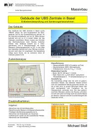
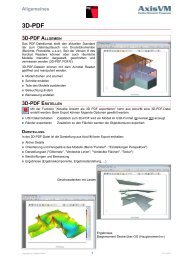
a total of over 30,000 licences used worldwide in over 150 countries<br />
Largest CAE Software Developer in Civil Engineering<br />
Branch Offices<br />
Shenyang<br />
MIDAS<br />
(Seoul)<br />
Taiwan<br />
Japan<br />
(Tokyo)<br />
Sales Offices<br />
KOZO KEIKAKU ENGINEERING<br />
ITOCHU Techno-Solutions<br />
JIP Techno Science<br />
CREA-TEC<br />
Cybernet Systems<br />
Advanced Nonlinear and Detail Analysis System Global NetworkModelling, Integrated Design & Analysis Software<br />
1
Advanced Nonlinear and Detail Analysis System<br />
<strong>midas</strong> <strong>FEA</strong> About <strong>midas</strong> <strong>FEA</strong><br />
05.<br />
Reliable<br />
MIDAS Quality Control System (MQCS)<br />
Certification for ISO 9001<br />
Verifications Examples<br />
Responsive user support<br />
04.<br />
Practical<br />
Evaluation of results<br />
Intuitive Construction Stage Definition<br />
Analysis Control<br />
Report Generation<br />
01.<br />
Unique<br />
Distinct and sophisticated visual interface<br />
Versatile representations of analysis results<br />
Powerful geometry modelling capabilities<br />
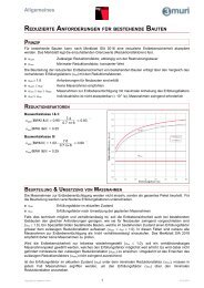
<strong>Why</strong><br />
<strong>midas</strong> <strong>FEA</strong>?<br />
03.<br />
Powerful<br />
Advanced Nonlinear and Detail Analysis System<br />
<strong>midas</strong> <strong>FEA</strong> is state of the art software, which defines a new paradigm for advanced nonlinear and detail analysis for civil and<br />
structural engineering applications including plain and reinforced concrete structures, concrete damage and cracking, plain and<br />
reinforced masonry structures, composite structures, steel structures, foundations, and offshore structures.<br />
<strong>midas</strong> <strong>FEA</strong>, combining a powerful pre/post processor and solvers stands for reliability and accurate solutions and is founded on<br />
expertise in geometry modelling, Auto-mesh generation, contemporary graphics and analysis technologies.<br />
02.<br />
Easy<br />
Intuitive Framework<br />
Task-oriented User Interface<br />
Modelling complex 3D geometries<br />
Automatic Mesh Generation<br />
Mesh manipulation<br />
Numerous Analysis Features<br />
Static and Dynamic Load and Boundary Conditions<br />
Unprecedented Fast Analysis Speed<br />
2
Advanced Nonlinear and Detail Analysis System<br />
<strong>midas</strong> <strong>FEA</strong> Application Areas<br />
01. Linear Static Analysis<br />
Multiple Load Cases & Combinations<br />
Output Control (Data, Node, Element)<br />
Result Coordinate System<br />
Extensive Element Library<br />
Equation Solvers<br />
- Direct Solvers<br />
Multi-frontal Sparse Gaussian Solver<br />
Skyline Solver<br />
- Iterative Solvers<br />
PCG, GMR (Unsymmetric)<br />
Construction Stage Analysis<br />
- Material Nonlinearity<br />
- Restart<br />
04. Reinforcement Analysis<br />
Reinforcements<br />
- Embedded Bar<br />
- Embedded Grid<br />
- Various Mother Elements<br />
(Solid, Plate, Axisymmetric, etc.)<br />
Post tensioned Prestress<br />
Material Nonlinearity<br />
Geometric Nonlinearity<br />
02. Eigenvalue Analysis<br />
Modal Analysis<br />
- Lanczos Method<br />
- Subspace Iteration<br />
- Sturm-Sequence Check<br />
- Include Rigid Body Modes<br />
- Modal Participation Factors<br />
Linear Buckling Analysis<br />
- Critical Load Factors<br />
- Buckling Modes<br />
- Load Combinations & Factors<br />
05. Heat of Hydration Analysis<br />
Heat Transfer<br />
- - Steady-State / Transient<br />
- - Heat Generation<br />
- - Conduction<br />
- - Convection<br />
- - Pipe Cooling<br />
Concrete Behaviour<br />
Behavior<br />
- - Creep / / Shrinkage<br />
- - Compressive Strength<br />
- - Design Codes (JCI, JSCE, etc.)<br />
Parametric Analysis<br />
- - Mutiple Material Sets<br />
- - Multiple BCs & Heat Sources<br />
- - Multiple Construction Sequences<br />
Advanced Nonlinear and Detail Analysis System<br />
03. Dynamic Analysis<br />
Transient / Frequency Response<br />
- Direct Integration<br />
- Mode Superposition<br />
- Time Forcing Function DB<br />
- Time Varying Loads<br />
- Ground Acceleration<br />
- Time History Plot / Graph<br />
Spectrum Response<br />
- SRSS, CQC, ABS<br />
- Design Spectrum DB<br />
- Seismic Data Generator<br />
06. Interface Nonlinearity Analysis<br />
Interface Elements<br />
- Point, Line, Plane<br />
- Pile (Solid-Line)<br />
Interface Models<br />
- Rigid<br />
- Coulomb Friction<br />
- Discrete Cracking<br />
- Crack Dilatancy<br />
- Bond-Slip<br />
- Combined CSC<br />
3
Advanced Nonlinear and Detail Analysis System<br />
<strong>midas</strong> <strong>FEA</strong> Application Areas<br />
07. Contact Analysis<br />
Contact Type<br />
- Weld Contact, General Contact<br />
Behaviour<br />
- Material Nonlinearity<br />
- Geometry Nonlinearity<br />
Results<br />
- Displacement<br />
- Stress<br />
- Contact force<br />
10. Fatigue Analysis<br />
Methods and Parameters<br />
- S-N Method (Stress-Life)<br />
- E-N Method (Strain-Life)<br />
- Load / Stress History<br />
- Rainflow Counting<br />
- Mean Stress Corrections<br />
- Stress Concentration Factor<br />
- Modifying Factors<br />
Results<br />
- Cycles to Failure<br />
- Safety Factor<br />
(Cycles to Failure /<br />
Desired Repetition)<br />
- Damage estimation<br />
08. Nonlinear Static Analysis<br />
Material Nonlinearity<br />
- von Mises, Tresca, Mohr-Coulomb,<br />
Drucker-Prager, Rankine,<br />
User Supplied Material<br />
Geometric Nonlinearity<br />
- Total Lagrangian, Co-rotational<br />
Iteration Method<br />
- Full Newton-Raphson, Modified<br />
Newton-Raphson, Arc-Length Method,<br />
Initial Stiffness<br />
11. Heat Transfer/Stress Analysis<br />
Steady-State & Transient<br />
Conduction, Convection<br />
Heat Flux<br />
Heat Flow<br />
Temperature Gradient Display<br />
Advanced Nonlinear and Detail Analysis System<br />
09. Cracking Analysis<br />
Total Strain Crack<br />
- Fixed & Rotating Crack Model<br />
Discrete Crack Model<br />
- Interface Nonlinearity<br />
Results<br />
- Crack Pattern<br />
- Element Status<br />
(Crack, Plasticity)<br />
12. CFD Analysis<br />
CFD Models<br />
- Turbulence Models<br />
RANS, k-, -<br />
- Compressible Flow<br />
- Incompressible Flow<br />
- Inviscid Flow<br />
- Unsteady Flow<br />
Discretisation Scheme<br />
- 2nd-order (Spatial)<br />
- Dual time stepping (Temporal)<br />
Boundary Condition<br />
- Far-field<br />
- Wall (Slip, Non-slip), etc.<br />
- Symmetric<br />
4
<strong>midas</strong> <strong>FEA</strong><br />
“Advanced Nonlinear and Detail Analysis System”<br />
01.<br />
Graphical User Interface<br />
Providing an integrated and efficient work environment for<br />
Modelling, Visualisation and Simulation<br />
<strong>midas</strong> <strong>FEA</strong> - Framework<br />
Observer / Navigation Window<br />
Works Tree<br />
Main Menu<br />
Tabbed Toolbars<br />
Task Pane<br />
Quick review for both global and<br />
detail view of analysis results<br />
A new concept tool, which enables the user<br />
to freely set optimal menu system<br />
A new concept menu system comprising frequently<br />
used menus<br />
Procedural sequence defined by the user for<br />
maximum efficiency<br />
Auto-links to manuals, technical papers and tutorials<br />
Links to corresponding dialogue boxes for ease of<br />
checking input data<br />
Property Window<br />
Property Window provides various<br />
property information for quick query/edit.<br />
Customise detailed graphic output for<br />
result generation<br />
Output Window<br />
Status Bar<br />
Context Menu<br />
5 Modelling, Integrated Design & Analysis Software
<strong>midas</strong> <strong>FEA</strong><br />
“Advanced Nonlinear and Detail Analysis System”<br />
02.<br />
Pre Processor<br />
The powerful pre-processor is founded on the expertise<br />
in geometry modelling, auto-mesh generation and powerful 3D graphic tools<br />
Display Mode<br />
Geometry Modelling<br />
Geometry Display Mode Local Prism Stitch to Solid<br />
<br />
<br />
<br />
<br />
Wireframe Transparency Shading<br />
Forming a solid model by extracting specific surface<br />
Forming a solid model by sewing surfaces<br />
Mesh Display Mode<br />
Sweep<br />
Loft & Extrude<br />
<br />
<br />
<br />
<br />
<br />
<br />
Feature Edge<br />
Transparency<br />
Shading<br />
<br />
Extrude along guide curve<br />
Create a solid model with<br />
variation of cross section (Tapered section)<br />
Customisation controls to easily view geometry or mesh sets<br />
Full graphics control for geometry and mesh sets<br />
Full graphics control to view interior shapes embedded in complex structures by<br />
transforming to wireframe, or control transparency for local/global parts of the model<br />
Perform the Boolean operation (Fuse, Cut, Embed) for geometry compatibility with<br />
more than two solid objects<br />
Using advanced geometry tools (Loft, Sew, Sweep, Local Prism) to convert<br />
2D geometry models to 3D geometry shapes<br />
Modelling, Integrated Design & Analysis Software<br />
6
<strong>midas</strong> <strong>FEA</strong><br />
“Advanced Nonlinear and Detail Analysis System”<br />
02.<br />
Pre Processor<br />
The powerful pre-processor is founded on the expertise<br />
in geometry modelling, auto-mesh generation and powerful 3D graphic tools<br />
Mesh Generation<br />
Automatic Surface/Solid Meshing<br />
Revolve Mesh<br />
Sweep Mesh<br />
Surface Automatic Mesh<br />
<br />
<br />
Automatically generate solid mesh by rotating<br />
2D-Mesh using reference axis<br />
Fill Mesh<br />
Automatically generate solid mesh by<br />
extruding 2D-Mesh using guide curve<br />
Project Mesh<br />
Solid Automatic Mesh<br />
<br />
<br />
<br />
<br />
Fill mesh creates 3D mesh sets between<br />
two 2D mesh shapes with similar element<br />
size discretisation.<br />
Automatically generate mesh by projecting<br />
a mesh on a reference plane<br />
Includes advanced meshing function : Auto-Mesh, Map-mesh & manual generation<br />
Mesh extraction method from 2D/3D mesh sets or directly from a geometry object<br />
Capability of generating 3D mesh for complex shapes using 2D Mesh sets<br />
Supports advanced meshing functions for complex geometry modelling : Manifold and<br />
non-manifold shapes<br />
Provides advanced mesh function such as Hybrid Meshing, Sub-Meshing as well as<br />
Auto-mesh, Map-mesh<br />
Fast mesh generation: 200,000 tetra elements per-minute<br />
7 Modelling, Integrated Design & Analysis Software
<strong>midas</strong> <strong>FEA</strong><br />
“Advanced Nonlinear and Detail Analysis System”<br />
02.<br />
Pre Processor<br />
The powerful pre-processor is founded on the expertise<br />
in geometry modelling, auto-mesh generation and powerful 3D graphic tools<br />
Mesh Size Control/Quality Assurance<br />
Frame to Solid (Direct Data Transfer with <strong>midas</strong> Civil)<br />
Mesh Size Control<br />
<br />
<br />
Mesh Quality Assurance<br />
Check & Verify<br />
- Free Edges<br />
- Free Faces<br />
- Manifold Edges<br />
- Non-manifold Edges<br />
- Check & Align ECS<br />
Quality Assurance<br />
- Aspect Ratio<br />
- Skew Angle<br />
- Taper (2D)<br />
- Warpage (2D)<br />
- Jacobian Ratio<br />
- Twist<br />
- Collapse (Tetra)<br />
- Length / Area<br />
Mesh Size Control<br />
Check Free Face<br />
Mesh Quality Plot<br />
Automatically imported solid models<br />
into <strong>midas</strong> <strong>FEA</strong><br />
Frame model in <strong>midas</strong> Civil<br />
Detailed model conversion for PSC Box sections including tendon profiles<br />
Automatically imported plate model in<br />
<strong>midas</strong> <strong>FEA</strong><br />
Various size control functions available to modify density of nodes and elements for<br />
complex geometry or variation of material properties<br />
Advanced size control functions such as Adaptive Seeding, which automatically controls<br />
mesh density based on shape characteristics<br />
Standard Mesh quality and assurance features to detect incompatibility or poor element quality<br />
Convert frame model and PSC section types in <strong>midas</strong> Civil into plate/solid models in <strong>midas</strong> <strong>FEA</strong><br />
Convert tendon profiles and embed them as bars from <strong>midas</strong> Civil into <strong>midas</strong> <strong>FEA</strong><br />
Modelling, Integrated Design & Analysis Software<br />
8
<strong>midas</strong> <strong>FEA</strong><br />
“Advanced Nonlinear and Detail Analysis System”<br />
03.<br />
Analysis<br />
Providing high-end linear/nonlinear analysis<br />
capabilities optimised for bridge and structural engineering<br />
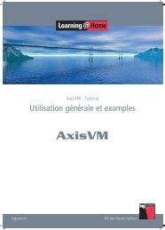
Linear Static Analysis<br />
Eigenvalue Analysis<br />
Linear Static Analysis<br />
Multiple Load Cases<br />
Result Combination and Transformation<br />
Modal Analysis<br />
Lanczos Method<br />
Subspace Iteration<br />
Equation Solvers<br />
Direct Solvers<br />
- Multi-frontal Sparse Gaussian Solver (Default)<br />
- Skyline Solver<br />
Iterative Solvers<br />
- Preconditioned Conjugate Gradient<br />
- Generalised Minimal Residual<br />
Plate Girder Bridge (Plate)<br />
Extradosed Bridge<br />
(1/2 Symmetric)<br />
<br />
<br />
<br />
Linear Buckling Analysis<br />
Steel Box Girder – Inner Support<br />
Critical Buckling Modes<br />
Buckling Modes<br />
Regulatory Load Combinations<br />
Model A Model B Model C Model D<br />
<br />
<br />
<br />
<br />
<br />
<br />
<br />
<br />
<br />
<br />
<br />
<br />
<br />
<br />
<br />
<br />
<br />
<br />
<br />
<br />
<br />
<br />
<br />
<br />
<br />
<br />
<br />
<br />
<br />
Net Solution time: Intel® Core Duo CPU @ 3GHz 2GB RAM<br />
Saddle at the Top of an Extradosed Bridge (Soiid)<br />
Steel Box Diaphragm<br />
(1/2 Symmetric)<br />
<br />
Fast and accurate analysis by using Multi-frontal Sparse Gaussian Solver<br />
Various load and boundary conditions (Applied load at any position, Distributed load<br />
for live/dead load, Multi Point Constraint etc.)<br />
Accurate analysis using higher order elements<br />
Eigenvalue Analysis : Lanczos Method & Subspace Iteration Method<br />
Generate load combination for buckling analysis<br />
Output buckling mode shape which has positive critical load factor (Option)<br />
Removing unnecessary buckling modes<br />
9 Modelling, Integrated Design & Analysis Software
<strong>midas</strong> <strong>FEA</strong><br />
“Advanced Nonlinear and Detail Analysis System”<br />
03.<br />
Analysis<br />
Providing high-end linear/nonlinear analysis<br />
capabilities optimised for bridge and structural engineering<br />
Dynamic Analysis<br />
Static Nonlinear Analysis<br />
Transient Response Analysis<br />
Direct Transient Response<br />
Modal Transient Response<br />
Time Forcing Function DB<br />
(54 Earthquake Acceleration<br />
Records)<br />
Material Models<br />
von Mises<br />
Tresca<br />
Mohr-Coulomb<br />
Drucker-Prager<br />
Rankine<br />
User-Supplied Material<br />
Failure Criteria<br />
Tresca<br />
Von-Mises<br />
Mohr-Coulomb<br />
Spectrum Response Analysis<br />
SRSS, CQC, ABS<br />
Design Spectrum DB<br />
Design Spectrum<br />
Seismic Wave<br />
Material Nonlinearity<br />
Hardening (Isotropic)<br />
Softening<br />
Rankine<br />
Drucker-Prager<br />
Geometric Nonlinearity<br />
Iteration Methods<br />
Total Lagrangian<br />
Response to the<br />
Longitudinal Seismic Force<br />
Response to the<br />
Transverse Seismic Force<br />
Iteration Methods<br />
Full Newton-Raphson<br />
Modified Newton-Raphson<br />
Arc-Length Method<br />
Initial Stiffness<br />
Initial Stiffness<br />
Newton-Rahpson<br />
Modified Newton<br />
-Rahpson<br />
Arc-Length<br />
Integral Bridge Modeling<br />
Acceleration at the Top of the Pier<br />
Supports the design response spectrum based on seismic database library<br />
Provides time history analysis by Direct Integration Method and Modal Time History Analysis<br />
Produces various time history analysis result graphs : nodal displacement/speed/acceleration,<br />
member force stress/strain of element<br />
Include a total of five constitutive models in addition to an user supplied material option for<br />
all types of material models including concrete and steel<br />
Consider effects of transverse varying stiffness and large deformation for structures<br />
undergoing material nonlinearity effects and large axial forces (Frame, Plate, and Solid models)<br />
Consider geometry and material nonlinear analysis simultaneously for frame,<br />
plate and solid elements<br />
Iterative analysis techniques : Initial Stiffness, Modified/Newton-Raphson, and Arc-Length<br />
Auto load step and restart options<br />
Modelling, Integrated Design & Analysis Software<br />
10
<strong>midas</strong> <strong>FEA</strong><br />
“Advanced Nonlinear and Detail Analysis System”<br />
03.<br />
Analysis<br />
Providing high-end linear/nonlinear analysis<br />
capabilities optimised for bridge and structural engineering<br />
Reinforcement Analysis<br />
Cracking Analysis<br />
Reinforcements (Rebar & Tendon)<br />
Embedded Bar/Grid<br />
Line Type Applied to Plate, Solid & Plain Stress<br />
Point Type Applied to Plain Strain & Axisymmetric<br />
<br />
Prestressing Tendon<br />
Pretension & Post-Tension<br />
Short-Term Loss: Friction, Slip & Elastic Deformation<br />
Long-Term Loss: Relaxation & Creep/Shrinkage<br />
Loss of Pretension<br />
Column Reinforcements of an Underground Station<br />
Cracking Models<br />
Total Strain Crack<br />
- Fixed Crack Model & Rotating Crack Model<br />
Discrete Crack Model<br />
- Interface Nonlinearity<br />
Results<br />
Crack Pattern (Crack Stress/Strain)<br />
Element Status<br />
- Cracking: Partially/Fully Open, Closed, Not Yet<br />
- Plasticity: Previously Plastic, Elastic, Plastic, Critical<br />
- Contact: No Contact, Slip, Stick<br />
PSC Box<br />
Load Step 1<br />
PSC Box<br />
Load Step 5<br />
1. tensioning<br />
limited penetration<br />
Prestressing Tendons in a PSC Box Bridge<br />
Concrete Crack Models<br />
Disc Normal: Opening Direction<br />
Disc Color: Magnitude<br />
Line: Shearing Direction<br />
tendon<br />
2. penetration at 1<br />
tendon<br />
3. penetration at 2<br />
tendon<br />
Discrete Crack<br />
Smeared Crack<br />
<br />
Unique embedded techniques enable users to model tendons and reinforcement<br />
regardless of neighbouring elements and nodal connectivity<br />
Analyses considering immediate loss (friction, slip and elastic deformation) and longterm<br />
loss (tendon relaxation, creep/shrinkage effect)<br />
Includes TSC (Total Strain Crack) for concrete crack analysis: Fixed and Rotating models<br />
Includes Reinforcement Analysis to portray the main concrete tension reinforcement<br />
Incorporates impact of rebar in tensile behaviour of concrete structures<br />
Includes analysis results and visualisation of crack pattern, direction and status of the element<br />
11 Modelling, Integrated Design & Analysis Software
<strong>midas</strong> <strong>FEA</strong><br />
“Advanced Nonlinear and Detail Analysis System”<br />
03.<br />
Analysis<br />
Providing high-end linear/nonlinear analysis<br />
capabilities optimised for bridge and structural engineering<br />
Heat Transfer Analysis<br />
Heat of Hydration Analysis<br />
Heat Transfer<br />
Fire in an Underground Structure<br />
Visco-Elastic Models<br />
Steady-State & Transient<br />
Conduction, Convection<br />
Heat Flux<br />
Heat Flow<br />
Temperature Gradient Display<br />
Creep-Shrinkage (Design Code)<br />
Temperature-Dependent Material<br />
Heat Transfer<br />
Steady-State & Transient<br />
Conduction, Convection<br />
Pipe Cooling<br />
Creep/Shrinkage Function<br />
Case I<br />
Parametric Analysis<br />
Guss Asphalt Pavement<br />
Temperature of Fire<br />
Multiple Material Sets<br />
Multiple BCs & Heat Sources<br />
Multiple Construction Sequences<br />
Heat Source Function<br />
Case II<br />
Modelling Case Analysis<br />
<br />
<br />
Temperature at<br />
the Top Plate<br />
<br />
<br />
<br />
<br />
<br />
<br />
<br />
<br />
<br />
<br />
<br />
<br />
<br />
<br />
<br />
<br />
<br />
Thermal Stress<br />
Temperature Distribution<br />
Process of Parametric Analysis<br />
Parametric Analysis Control<br />
Determine the time-dependent temperature distribution and heat transfer<br />
characteristics for structures exposed to high temperatures<br />
Thermal stress analysis considering heat transfer phenomenon such as conduction, convection<br />
Perform linear analysis considering the variance in material's characteristics<br />
(intensity, specific heat, conductivity) with respect to temperature<br />
Heat transfer analysis by convection, conduction of concrete hydration heat and<br />
Thermal stress analysis which considers creep/dry shrinkage<br />
Perform creep/dry shrinkage and heat transfer analysis: heat of hydration and thermal coefficient<br />
Use general data to perform a parametric analysis<br />
Model high order elements to obtain accurate results (output result: nodal temperature,<br />
nodal displacement, element stress/strain, heat flux, heat flow, temperature gradient display,<br />
crack index)<br />
Modelling, Integrated Design & Analysis Software<br />
12
<strong>midas</strong> <strong>FEA</strong><br />
“Advanced Nonlinear and Detail Analysis System”<br />
03.<br />
Analysis<br />
Providing high-end linear/nonlinear analysis<br />
capabilities optimised for bridge and structural engineering<br />
Interface Nonlinear Analysis<br />
Static Contact Analysis<br />
Interface Models<br />
Contact Types<br />
Coulomb Friction<br />
Discrete Cracking<br />
Crack Dilatancy<br />
Bond-Slip<br />
Combined (Cracking-Shearing-Crushing)<br />
Steel-Concrete<br />
Composite Girder<br />
Weld Contact<br />
General Contact<br />
Behaviour<br />
Material Nonlinearity<br />
Geometry Nonlinearity<br />
Plate<br />
Contact<br />
Boundary<br />
Bolts<br />
Steel<br />
Results<br />
Interface<br />
Displacement<br />
Stress<br />
Contact Force<br />
Concrete<br />
Concrete Block<br />
Interface<br />
Steel Bar<br />
Displacement<br />
Stress<br />
Interface Stress<br />
Solid Stress<br />
Simulates frictional behaviour for heterogeneous material such as reinforced concrete, etc.<br />
Provides 5 interface models to describe nonlinear behaviour of heterogeneous material<br />
at contact surfaces<br />
Interface Model: Coulomb Friction, Discrete Cracking, Crack Diatancy, Bond-slip,Combined<br />
(Cracking-Shearing-Crushing)<br />
Perform contact analysis for structural parts (joint & connections) to simulate connections,<br />
cyclic loadings and contact frequency (Considering linear and nonlinear material models)<br />
Penalty method assigned for springs between contact surface and node<br />
13 Modelling, Integrated Design & Analysis Software
<strong>midas</strong> <strong>FEA</strong><br />
“Advanced Nonlinear and Detail Analysis System”<br />
03.<br />
Analysis<br />
Providing high-end linear/nonlinear analysis<br />
capabilities optimised for bridge and structural engineering<br />
Fatigue Analysis<br />
CFD (Computational Fluid Dynamics) Analysis<br />
Methods and Parameters<br />
S-N Method (Stress-Life)<br />
E-N Method (Strain-Life)<br />
Load / Stress History<br />
Rainflow Counting<br />
Mean Stress Corrections<br />
Stress Concentration Factor<br />
Modifying Factors<br />
Calculation Objects<br />
Boundary Nodes Only (Default)<br />
Nodes of Selected Mesh Sets<br />
Results<br />
Cycles to Failure<br />
Safety Factor<br />
(Cycles to Failure / Desired<br />
Repetition)<br />
Linear Analysis<br />
Rainflow Counting & S-N Curve<br />
Stress Amplitude<br />
CFD Models<br />
Turbulence Models<br />
(RANS, k-, q-)<br />
Compressible Flow<br />
Incompressible Flow<br />
Inviscid Flow<br />
Unsteady Flow<br />
Discretisation Scheme<br />
2nd-order (Spatial)<br />
Dual time stepping (Temporal)<br />
Boundary Condition<br />
Far-field<br />
Wall (Slip, Non-slip), etc.<br />
Velocity contour<br />
CFD model= Bridge Section<br />
Pressure contour<br />
Vorticity contour<br />
Damage<br />
Life Cycle<br />
Fatigue Analysis: Display structure failure phenomenon based on a cyclic loading<br />
pattern with reduced yield strength<br />
Calculate stress amplitude Applying Rainflow Counting & S-N Curve Calculating<br />
the fatigue life (life cycle) and extent of damage<br />
Investigate bridge’s stability resistance to wind by visually determining airflow pattern<br />
Perform Steady state analysis / Unsteady analysis and Laminar Flow /<br />
Turbulence Flow analysis<br />
Calculate aerodynamic force coefficients and determine pressure distribution &<br />
turbulence kinetic energy<br />
Modelling, Integrated D esign & A nalysis Software<br />
14
<strong>midas</strong> <strong>FEA</strong><br />
“Advanced Nonlinear and Detail Analysis System”<br />
04.<br />
Post Processor<br />
Providing practical output functions and<br />
effective result visualisation for analysing structure behaviour<br />
Type of Plots / Interactive Legend Control<br />
Extract Result / Probe Result<br />
Iso Surface Plot<br />
Clipping Plot<br />
Illustrate cross-sectional results by<br />
defining cutting surfaces.<br />
Legend Control<br />
Full control on legend to<br />
modify range of output results.<br />
Probe Result<br />
Display tagged results on<br />
selected nodes or elements<br />
Original Plot<br />
Mirror Plot<br />
Illustrate full scale results for symmetry models<br />
Hybrid Plot<br />
Illustrate contour plot and<br />
vector plot simultaneously.<br />
Slice Plot<br />
Check results using defined plane slices<br />
for viewing localised behaviour.<br />
Extract results in a table<br />
Extract Result<br />
Extract Result enables to output<br />
only desired data from the analysis results<br />
Load-Displacement graph<br />
Intuitive graphical output functions to verify and illustrate the analysis results<br />
Control range of contour or colour spectrum with Legend Control function<br />
Extract Results: Extract results directly from nodes or elements for all the stages<br />
Probe Results: Display tags on nodes or elements with corresponding results<br />
Easily filter Min or Max results using Probe Results<br />
15 Modelling, Integrated Design & Analysis Software
<strong>midas</strong> <strong>FEA</strong><br />
“Advanced Nonlinear and Detail Analysis System”<br />
04.<br />
Post Processor<br />
Providing practical output functions and<br />
effective result visualisation for analysing structure behaviour<br />
On Curve Diagram / Local Direction Force Sum<br />
Virtual Transformation<br />
On Curve Diagram<br />
Integral Bridge<br />
Deck<br />
Diaphragm<br />
Local Direction Force Sum<br />
Plate Stress<br />
Abutment<br />
Pier<br />
Girder<br />
Local Direction Force Sum<br />
<br />
Pier<br />
Abutment<br />
Extract results from two user-defined points or acurve to display output diagram and table<br />
Local Direction Force Sum – Extract member force or moment results at a specific section<br />
Intuitive tools to investigate the interior parts of a complex model based on virtual<br />
transformation of mesh sets<br />
Modelling, Integrated Design & Analysis Software<br />
16
<strong>midas</strong> <strong>FEA</strong><br />
“Advanced Nonlinear and Detail Analysis System”<br />
05.<br />
Applications<br />
Specialised application cases for civil engineering<br />
Detailed Analysis of Steel Box Girder & Coping Connection<br />
Detailed analysis for concrete structures – Stress concentration analysis<br />
Geometry Modelling<br />
Detailed review of tendon anchorage<br />
Detailed analysis effects for cables installed on bridge saddle<br />
Geometry Modelling<br />
Steel Box Girder Modelling<br />
Geometry Modelling<br />
Steel Coping<br />
Modelling<br />
Results<br />
Geometry Modelling<br />
Contour Plot<br />
Analysis Results<br />
Detailed review of Anchorage block<br />
Stress at Connections<br />
Displacement Contour<br />
Strain at Connections<br />
Geometry Modelling Contour Plot Slice Plot<br />
Perform linear static analysis for connection between steel box girder and coping<br />
Review stress distribution resultant from bending moment and torsion at cross sectional diaphragms<br />
Define rigid diaphragm nodes at cut end boundaries of the structure<br />
Perform linear static analysis for stress concentration for anchorage block<br />
Review tensile stress and bursting stress for zones with high stress concentrations<br />
(tendon, cable anchor and suspension bridge saddle)<br />
17 Modelling, Integrated Design & Analysis Software
<strong>midas</strong> <strong>FEA</strong><br />
“Advanced Nonlinear and Detail Analysis System”<br />
05.<br />
Applications<br />
Specialised application cases for civil engineering<br />
3D FEM Analysis for Long-span FSM Bridge<br />
Detailed Behaviour for 1 pylon Extradosed Bridge<br />
Geometry Modelling<br />
Construction Stage 3<br />
Construction<br />
Stage 2<br />
Construction Stage 1<br />
Displacement Contour<br />
Solid Geometry<br />
Construction Stage Analysis<br />
Tendon placing<br />
Construction Stage<br />
On-curve diagram<br />
(longitudinal stress)<br />
Construction Stage<br />
for 30 days<br />
Construction Stage<br />
for 30 days<br />
Global Model of<br />
Extradosed Bridge<br />
Construction Stage<br />
for 60 days<br />
Construction Stage<br />
for 60 days<br />
Prestress forces at tendons<br />
Stress distribution<br />
(pylon)<br />
Construction Stage<br />
for 90 days<br />
Construction Stage<br />
for 90 days<br />
Stress distribution after<br />
installing key segments<br />
Stress distribution before<br />
installing key segments<br />
Normal Stress per construction stage<br />
Tensile force per each construction stage<br />
Perform 3D FE analysis to verify the stability of a long span FSM bridge<br />
(over 70m long) with varying geometry dimensions at cross-section and top deck width<br />
Determine stress variations and tendon prestress distribution using construction stage<br />
analysis at critical sections<br />
Obtain accurate reaction distribution results at bearing points compared to frame analysis<br />
Verify transversely distributed forces of one pylon extradosed bridge<br />
Verify detailed behaviour of the BCM bridge using construction stage analysis during<br />
installation of key segment parts<br />
Modelling, Integrated D esign & A nalysis Software<br />
18
<strong>midas</strong> <strong>FEA</strong><br />
“Advanced Nonlinear and Detail Analysis System”<br />
05.<br />
Applications<br />
Specialised application cases for civil engineering<br />
Reviewing Redundancy for Plate Girder System<br />
Load Carrying Capacity Evaluation for PSC Box Bridge<br />
Modelling of Extradosed Bridge Principal Stress Radial Tendon Prestress Force<br />
Detail model of Plate Girder system<br />
von Mises Stress Plasticity<br />
Crack Analysis<br />
Load Step 1 (0.4)<br />
Load Step 4<br />
(0.5)<br />
Load Step 6<br />
(0.7625)<br />
Load Step 6 (0.75)<br />
Max Deformation vs. Load Increment Curve<br />
Load Step 16 (1.0)<br />
von Mises Stress Shape with Load Increment<br />
Crack Status<br />
Crack pattern per load step<br />
Model the redundancy effects on a plate girder bridge<br />
Simulate nonlinear behaviour of the model using von-Mises constitutive model and<br />
Newton-Raphson iterative method<br />
Monitor failure mechanism based on ultimate state of nonlinear material models<br />
Behavioural characteristic results different from elastic analysis can be caused by<br />
material nonlinearity in the case of actual structure in extreme conditions<br />
Evaluate stress condition considering the nonlinearity of the ultimate condition<br />
Determine crack pattern and status for concrete crack analysis applying<br />
TSC (Total Strain Crack) model<br />
19 Modelling, Integrated Design & Analysis Software
<strong>midas</strong> <strong>FEA</strong><br />
“Advanced Nonlinear and Detail Analysis System”<br />
05.<br />
Applications<br />
Specialised application cases for civil engineering<br />
Application for Heat of Hydration Analysis Using Parametric Analysis Feature<br />
Contact Analysis of Bolt Connection<br />
Selecting Hydration Analysis Model and Parameter Analysis Result for each Parameter Overview of Analysis model<br />
<br />
<br />
<br />
<br />
<br />
<br />
<br />
<br />
<br />
<br />
<br />
<br />
<br />
<br />
<br />
<br />
<br />
<br />
Heat Function<br />
Application<br />
<br />
<br />
<br />
<br />
<br />
<br />
Heat<br />
Distribution<br />
<br />
Geometry Modelling<br />
<br />
<br />
<br />
<br />
<br />
<br />
<br />
<br />
Bolt Connection of Web Plate on the Steel Bridge<br />
Base plate and Bolt Modelling (1/8 model)<br />
<br />
<br />
<br />
<br />
<br />
<br />
Case 2 Case 3 Case 4<br />
Substrate and<br />
connection plate<br />
Deformed Shape<br />
Heat Function<br />
Application<br />
Heat Function<br />
Application<br />
Heat Function<br />
Application<br />
Defining contact<br />
surface<br />
Heat<br />
Distribution<br />
Heat<br />
Distribution<br />
<br />
<br />
Bolt<br />
Stress of contact surface<br />
Model Configuration for Contact Analysis<br />
Contact Analysis Results<br />
Perform analysis consisting of cases for various factors<br />
(casting, convection boundary, material. thermal characteristics, self-weight) for<br />
controlling heat of hydration effect in a model<br />
Select casting height and material parameters through parametric analysis for<br />
finding crack index range<br />
Define contact surface between base plate, gusset plate and bolts to transfer contact forces<br />
Perform nonlinear analysis considering contact condition between members<br />
Penalty method is applied in order to intercept the interaction of the contact surface based<br />
on spring elements<br />
Modelling, Integrated Design & Analysis Software<br />
20
<strong>midas</strong> <strong>FEA</strong><br />
“Advanced Nonlinear and Detail Analysis System”<br />
05.<br />
Applications<br />
Specialised application cases for civil engineering<br />
Fatigue Analysis for Steel Bridge<br />
Thermal Stress Examination According to the Guss Asphalt Construction<br />
Fatigue Analysis<br />
Heat Deformation of Steel Box Girder<br />
Heat Transfer Analysis<br />
<br />
<br />
Steel Box Girder Model<br />
Stress Amplitude According<br />
to Variable Loads<br />
(a) Limitation of horizontal reaction for<br />
steel box girder bearing<br />
<br />
<br />
Temperature distribution<br />
at 30 Min.<br />
Life Cycle<br />
Damage<br />
<br />
<br />
(b) Limitation of negative reaction for<br />
steel box girder bearing<br />
<br />
<br />
<br />
Analysis model for verification<br />
Temperature variation with time<br />
<br />
<br />
<br />
Heat Stress Analysis<br />
(c) Ensure joint gap for steel box girder bearing<br />
<br />
<br />
<br />
<br />
<br />
<br />
<br />
(d) Ensure shrinkage of joint gap for<br />
steel box girder bearing.<br />
Deformed shape according<br />
to one-sided placing<br />
Perform static analysis on structures with applied static loads and live loads to calculate<br />
the amplitude stress<br />
Set maximum amplitude stress for S-N Curve of steel box and limitation of amplitude stress<br />
Calculate fatigue life (fatigue iteration) and failure considering the influence by<br />
Mean stress correction<br />
When constructing Guss asphalt, the section of steel box temporarily generates<br />
high temperature difference<br />
When constructing previous Guss asphalt, problems arising at expansion joints or<br />
damage cases for the cross clamps depend on the vertical direction of the displacement<br />
Preparation for effective construction plan through the thermal stress examination before<br />
the Guss asphalt construction<br />
21 Modelling, Integrated Design & Analysis Software
<strong>midas</strong> <strong>FEA</strong><br />
“Advanced Nonlinear and Detail Analysis System”<br />
05.<br />
Applications<br />
Specialised application cases for civil engineering<br />
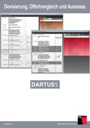
Underground station and fire analysis of tunnel<br />
Fire Analysis Concept<br />
Temperature: 25 degrees<br />
Fire Analysis Process Heat Transfer Analysis of Underground Station Heat Transfer Analysis of Tunnel Fire<br />
Basic section design<br />
Cloth: For 25 mm<br />
Temperature: 25 degrees<br />
1 hour elapsed<br />
Section design of general external<br />
forces by strength design method<br />
Temperature : 70 degrees<br />
Temperature<br />
:500 degrees<br />
Temperature : 80 degrees<br />
Exfoliation of concrete<br />
Temperature: 650 degrees<br />
Partial rupture<br />
2 hour elapsed<br />
Deformation of<br />
reinforcement<br />
4 hour elapsed<br />
Heat transfer analysis<br />
Heat transfer analysis and calculation<br />
of temperature distribution<br />
from the demanded fire time<br />
Strength reduction computation<br />
Temperature dependent strength<br />
computation <br />
Temperature: 100 degrees<br />
Section reexamination<br />
Buckling of reinforcement<br />
Temperature: 850 degrees<br />
Edge ruptured<br />
Mn calculation & examination<br />
in demanded fire time<br />
(+)Mn (+)Mmax (service load)<br />
<br />
Temperature distribution of underground station by time frame<br />
Temperature distribution of tunnel by time frame<br />
Simulate and analyse fire exposure for underground<br />
structure based on reference code<br />
Perform heat transfer analysis using temperature<br />
dependent material properties<br />
Estimate the safety factor for damaged sections<br />
exposed to fire<br />
Duration: 5 minutes<br />
Duration: 30 minutes<br />
Duration: 5 minutes<br />
Duration: 30 minutes<br />
Duration: 3 hours<br />
Duration: 1 hour<br />
Duration: 3 hours<br />
Duration: 1 hour<br />
Modelling, Integrated Design & Analysis Software<br />
22
<strong>midas</strong> <strong>FEA</strong><br />
Advanced Nonlinear and Detail Analysis System<br />
Copyright Since 1989 MIDAS Information Technology Co., Ltd. All rights reserved.<br />
www.MidasUser.com<br />
MIDAS (UK)<br />
Suite 1005, 1 Lyric Square, London W6 0NB T 020 3586 7533 F 020 3006 8855 E UKsupport@<strong>midas</strong>user.com