The development of composite fibre sailplanes - Ingenia
The development of composite fibre sailplanes - Ingenia
The development of composite fibre sailplanes - Ingenia

You also want an ePaper? Increase the reach of your titles
YUMPU automatically turns print PDFs into web optimized ePapers that Google loves.
TECHNOLOGY<br />
AFANDI DARLINGTON<br />
OPTIMAL AERODYNAMICS LTD<br />
Virtuous circle<br />
<strong>The</strong> <strong>development</strong><br />
<strong>of</strong> <strong>composite</strong><br />
<strong>fibre</strong> <strong>sailplanes</strong><br />
This article is based on the lecture<br />
given by Peter Hearne to the Royal<br />
Academy <strong>of</strong> Engineering in May<br />
2002, and traces the <strong>development</strong><br />
<strong>of</strong> <strong>sailplanes</strong> from the early roots in<br />
the 1920s and 30s, through the<br />
revolution <strong>of</strong> <strong>composite</strong> structures in<br />
the 1950s, to the superships <strong>of</strong> 2000<br />
which are capable <strong>of</strong> lift to drag<br />
ratios <strong>of</strong> 70. <strong>The</strong> engineering behind<br />
this evolution in performance is<br />
described and a look into the<br />
enabling technologies <strong>of</strong> the future<br />
is attempted.<br />
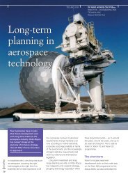
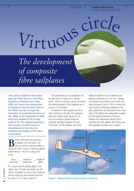
Before I describe the evolution<br />
<strong>of</strong> gliders over the past 100<br />
years it will be useful to define a<br />
‘figure <strong>of</strong> merit’ used to measure gliding<br />
performance – the lift to drag ratio<br />
(L/D):<br />
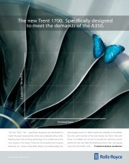
<strong>The</strong> performance <strong>of</strong> a sailplane can<br />
be described in terms <strong>of</strong> a ‘speed<br />
polar’, which is simply a graph showing<br />
the sinking speed <strong>of</strong> the sailplane as a<br />
function <strong>of</strong> airspeed.<br />
In addition to the requirement for a<br />
high maximum L/D ratio, the sailplane<br />
pilot also desires high values <strong>of</strong> L/D<br />
across as large a speed range as<br />
possible, typically between 40 and<br />
120 knots, as this enables very long<br />
Total reaction<br />
distance flights to be completed, and<br />
gliding competitions to be won. Gliding<br />
competitions are speed races held over<br />
fixed courses <strong>of</strong> up to 750 km where the<br />
only sources <strong>of</strong> energy available to the<br />
pilot, apart from the aeroplane tow at the<br />
start <strong>of</strong> the flight, are updraughts created<br />
by the heating influence <strong>of</strong> the sun.<br />
Despite the capricious nature <strong>of</strong> the<br />
weather and with gliders <strong>of</strong>ten flying over<br />
inhospitable mountainous or desert<br />
Lift<br />
θ<br />
Horizontal<br />
lift to<br />
drag ratio<br />
=<br />
weight to<br />
=<br />
drag ratio<br />
angle <strong>of</strong><br />
glide<br />
Flight path<br />
ingenia<br />
26<br />
For cross-country gliding flights, the<br />
higher the L/D ratio the better, as this<br />
allows the glider to cover more distance<br />
before having to find another thermal<br />
to climb in, or a field to land in!<br />
θ<br />
Weight<br />
Figure 1 Gliding flight (courtesy <strong>of</strong> Steve Longland)
TECHNOLOGY<br />
B<br />
terrain, speeds <strong>of</strong> 130–150 km/h are<br />
routinely achieved during top-level<br />
competitions. Gliding is a sport where<br />
the UK is seriously successful: in 2001,<br />
five out <strong>of</strong> ten World Championship<br />
classes were won by British pilots<br />
together with three out <strong>of</strong> ten silver<br />
medals, a feat not achieved in any other<br />
British sport.<br />
<strong>The</strong> design drivers that determine<br />
the L/D ratio are:<br />
●<br />
●<br />
●<br />
●<br />
●<br />
Sinking speed, V s<br />
wing span<br />
wing aer<strong>of</strong>oil shape<br />
fuselage shape and wetted area<br />
surface waviness<br />
weight<br />
all <strong>of</strong> which are critically dependent on<br />
the airframe construction material.<br />
Surface waviness and finish are<br />
crucially important to achieving laminar<br />
flow in the viscous ‘boundary layer’ <strong>of</strong><br />
air adjacent to the surface <strong>of</strong> the glider<br />
– if the surface is too wavy or rough the<br />
laminar boundary layer will be tripped<br />
into a turbulent state with a large<br />
increase in drag.<br />
<strong>The</strong> first documented glider was the<br />
Cayley ‘man-carrying glider’ <strong>of</strong> 1853.<br />
This device had a large wing composed<br />
<strong>of</strong> a sail attached to a wooden<br />
framework, which took up its lifting<br />
aer<strong>of</strong>oil shape only in an airflow. Control<br />
was achieved by vertical and horizontal<br />
tail surfaces connected to the ‘pilot’ –<br />
actually Cayley’s erstwhile coachman,<br />
as Cayley was 80 years <strong>of</strong> age – by a<br />
wooden tiller as in a sailing boat.<br />
A<br />
Figure 2 <strong>The</strong> speed polar<br />
Airspeed, V<br />
L/D MAX = B/A<br />
Whilst Cayley’s glider did fly for a short<br />
distance, his achievements were quickly<br />
forgotten after his death in 1857 and<br />
despite the efforts <strong>of</strong> Lilienthal in the<br />
1890s and the Wright brothers in<br />
1900–02, it was not until the late 1920s<br />
that practical gliders were produced<br />
and available to the everyday ‘club’<br />
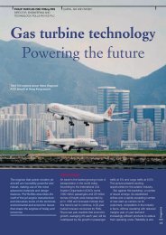
pilot. Typical <strong>of</strong> this early generation <strong>of</strong><br />
<strong>sailplanes</strong> is the beautiful Minimoa,<br />
designed by German pilot Wolf Hirth in<br />
1936.<br />
It was an advanced machine for its<br />
time, featuring a cantilevered wing<br />
rather than the strut-bracing which was<br />
common on the gliders that preceded<br />
it. <strong>The</strong> wooden structure was fabriccovered<br />
and the wingspan was close to<br />
the practical limit for wood at 17 m with<br />
an aspect ratio <strong>of</strong> 19. (Aspect ratio is a<br />
measure <strong>of</strong> the slenderness <strong>of</strong> the wing<br />
and is equal to wingspan 2 /wing area.)<br />
<strong>The</strong> wing section used was the very<br />
thick Gottingen 601, and possessed<br />
limited laminar flow, leading to a<br />
modest maximum L/D <strong>of</strong> only 28.<br />
Besides giving low performance, the<br />
wooden structure required highly skilled<br />
craftsmen to build it and was vulnerable<br />
to handling damage.<br />
Aerodynamic design techniques<br />
progressed rapidly during World War 2<br />
and aer<strong>of</strong>oil sections capable <strong>of</strong><br />
significant laminar flow were available<br />
Figure 3 Minimoa glider <strong>of</strong> 1936<br />
to sailplane designers immediately after<br />
the war was over in 1945; however,<br />
these proved impractical with the<br />
wooden structures in use at this time<br />
as the small lumps and bumps on the<br />
surface <strong>of</strong> the glider tripped the laminar<br />
boundary layer into a higher-drag<br />
turbulent boundary layer. Even<br />
extensive filling and pr<strong>of</strong>iling <strong>of</strong> the<br />
structure was only partially successful<br />
due to the instability <strong>of</strong> wooden<br />
structures caused by temperature and<br />
humidity variations. What was needed<br />
was a much smoother surface.<br />
<strong>The</strong> breakthrough was initiated in<br />
Germany in 1952, when Stuttgart<br />
Akaflieg began studying laminated<br />
paper/balsa core sandwich structures<br />
for sailplane use. This system failed<br />
to meet the necessary strength<br />
requirements, but in 1955 the paper<br />
was replaced by woven glass <strong>fibre</strong><br />
cloth and the construction method for<br />
all modern <strong>composite</strong> aircraft was<br />
born.<br />
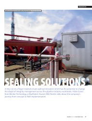
<strong>The</strong> first glider to make use <strong>of</strong> glass<br />
<strong>fibre</strong> reinforced plastic was the Akaflieg<br />
Stuttgart fs-24 Phoenix, designed by<br />
the brilliant German designers Richard<br />
Eppler and Hermann Nagele. <strong>The</strong><br />
Phoenix was a conservative design<br />
but even so had a maximum L/D <strong>of</strong><br />
38 which exceeded all wooden gliders<br />
that had preceded it.<br />
ingenia<br />
27
TECHNOLOGY<br />
ingenia<br />
Figure 4 <strong>The</strong> fs-24 Phoenix<br />
Before we move on in this story, a few<br />
words on the Akafliegs or ‘academic<br />
flying groups’. <strong>The</strong> incomparable<br />
Akafliegs are special sub-departments<br />
<strong>of</strong> German university technical faculties<br />
in which interested students and staff<br />
take part in the whole process <strong>of</strong><br />
concept, design, manufacture and<br />
testing <strong>of</strong> cutting-edge state-<strong>of</strong>-the-art<br />
<strong>sailplanes</strong>, over a five- to seven-year<br />
period. <strong>The</strong> Akafliegs combine:<br />
●<br />
●<br />
●<br />
●<br />
●<br />
enthusiastic young scientists and<br />
engineers who are active<br />
participants in the sport with a high<br />
level <strong>of</strong> personal achievement<br />
ability and opportunity at an early<br />
career stage to explore new<br />
advanced technology without the<br />
constraints <strong>of</strong> commercial risk<br />
the mature support and guidance <strong>of</strong><br />
older faculty members who are<br />
usually ex-Akaflieg members<br />
support from local industry which<br />
benefits from technology developed<br />
within the Akaflieg and from<br />
employment <strong>of</strong> ex-Akaflieg students<br />
upon graduation<br />
a nursery for the types <strong>of</strong> skills an<br />
advanced country needs in the<br />
twenty-first century.<br />
<strong>The</strong> success <strong>of</strong> the German Akaflieg<br />
system can be seen not only by the<br />
success <strong>of</strong> the German sailplane<br />
manufacturing industry, which is worldleading,<br />
but also in ex-Akaflieg<br />
members who are active in senior<br />
management <strong>of</strong> the German aerospace<br />
industry. It is a system that should be<br />
encouraged in the UK by partnership<br />
between academia and industry.<br />
Returning to our story, the smooth<br />
surfaces available using <strong>composite</strong><br />
structures had unlocked the<br />
performance <strong>of</strong> laminar flow wing<br />
sections whilst at the same time<br />
providing higher tensile strength and<br />
stiffness that allowed larger wingspan<br />
gliders to be built. In addition, the<br />
smooth wing surfaces were stable<br />
over the long term, reducing the<br />
maintenance requirement compared<br />
with the ageing wooden gliders.<br />
<strong>The</strong> early 1960s saw a proliferation<br />
<strong>of</strong> glass<strong>fibre</strong> sailplane designs in the<br />
German Akafliegs including the<br />
Braunschweig SB6 <strong>of</strong> 1961 designed<br />
by Bjorn Stender and his team. Stender<br />
went on to design the BS-1 sailplane,<br />
similar to the D-36 described below,<br />
which went into production in 1966.<br />
Meanwhile the H-301 Open Libelle<br />
designed by Wolfgang Hutter and<br />
Eugen Hanle became the first<br />
<strong>composite</strong> glider to be mass-produced<br />
with 100 built between 1964 and 1969.<br />
Another significant glider in our story<br />
was the very advanced Akaflieg<br />
Darmstadt D-36 ‘Circe’ <strong>of</strong> 1965. Whilst<br />
the 17.8 m wingspan <strong>of</strong> the D-36 had<br />
raised the L/D to 44, the D-36 was<br />
important because it pioneered the use<br />
<strong>of</strong> trailing edge flaps to increase the<br />
performance at high speeds between<br />
70 and 90 knots, where the flap was<br />
deflected upwards to increase the<br />
extent <strong>of</strong> laminar flow over the lower<br />
wing surface. Flaps have become a<br />
standard design feature on highperformance<br />
<strong>sailplanes</strong> ever since.<br />
<strong>The</strong> manufacturing methods used in<br />
production <strong>of</strong> the Phoenix remain<br />
basically unchanged today due to the<br />
Figure 5 <strong>The</strong> D-36 Circe<br />
high price and repair difficulty <strong>of</strong> more<br />
modern techniques such as autoclavecured<br />
pre-impregnated (pre-preg)<br />
materials. <strong>The</strong> benefits <strong>of</strong> pre-preg<br />
over traditional wet lay-up carbon <strong>fibre</strong><br />
<strong>composite</strong> structures are tabulated<br />
below:<br />
Wet lay-up<br />
Pre-preg<br />
Weight 100% 95%<br />
Strength 100% 110%<br />
Fibre volume 60% 70–75%<br />
Cost 1 2 or 3<br />
Repair ease Moderate Complex<br />
Table 1 Benefits <strong>of</strong> pre-preg over wet<br />
lay-up for carbon <strong>composite</strong>s<br />
Carbon <strong>fibre</strong> pultrusions with their<br />
higher material allowables are beginning<br />
to be used in gliders such as the<br />
world’s largest glider, the 30.8 m span<br />
Eta. A pultrusion is formed when<br />
structural <strong>fibre</strong>s are drawn through a<br />
heated die together with resin which<br />
polymerises, forming a <strong>composite</strong><br />
material with very closely controlled<br />
<strong>fibre</strong> volume and orientation.<br />
<strong>The</strong> Eta wing has an aspect ratio <strong>of</strong><br />
51.3 and a maximum L/D <strong>of</strong> 70, and is<br />
easily the most efficient aircraft<br />
conceived by mankind to date.<br />
Besides improvements in material<br />
science, great advances have been<br />
made in aerodynamics to maximise the<br />
extent <strong>of</strong> low-drag laminar flow over the<br />
wings, fuselage and empennage <strong>of</strong> a<br />
glider such as the Eta.<br />
Modern computation fluid dynamics<br />
(CFD) s<strong>of</strong>tware has been used to<br />
design both the 2-D wing aer<strong>of</strong>oil<br />
section, as well as the more<br />
complicated three-dimensional regions<br />
such as the wing-fuselage fairing and<br />
wingtip. Subtle changes in wing aer<strong>of</strong>oil<br />
shape in the wing root region reduce<br />
the triangular shaped turbulent ‘wedge’<br />
<strong>of</strong> airflow to reduce drag. At the<br />
wingtip, optimised winglets reduce liftinduced<br />
drag by up to 5%, further<br />
boosting L/D higher.<br />
28
TECHNOLOGY<br />
Figure 6 Pfenninger’s 100:1 L/D glider design <strong>of</strong> 1985<br />
With currently available technology,<br />
glider performance has reached a<br />
plateau, and ever enlarging the<br />
wingspan to increase L/D leads to<br />
gliders that are impractical to handle on<br />
the ground. A recent design exercise<br />
undertaken by students at Delft<br />
University <strong>of</strong> Technology in Holland has<br />
shown that to reach an L/D <strong>of</strong> 100 the<br />
wingspan must be increased to 42 m!<br />
A technology leap is required.<br />
<strong>The</strong> technology leap most likely to<br />
occur will be boundary layer suction,<br />
probably using solar-powered suction<br />
pumps to suck away the turbulent<br />
boundary layer that exists over 40% <strong>of</strong><br />
the typical glider. Whilst a design for a<br />
similar glider was proposed in 1985 by<br />
Walter Pfenninger (although this design<br />
used a windmilling propeller to drive the<br />
boundary layer suction pumps rather<br />
than solar cells), the manufacturing costs<br />
involved mean such a glider cannot be<br />
produced today at an affordable cost.<br />
Promising <strong>development</strong>s are under<br />
way however, such as pneumatic<br />
drilling <strong>of</strong> tiny holes through solar cell<br />
material, again at TU Delft, that will<br />
allow such a sailplane to be produced<br />
at moderate cost.<br />
Boundary layer suction <strong>sailplanes</strong> will<br />
<strong>of</strong>fer the opportunity to smash the<br />
existing world gliding distance record<br />
Figure 7 CFD mesh for a sailplane<br />
wing-fuselage winglet<br />
junction<br />
which currently stands at 3008 km, with<br />
the potential <strong>of</strong> flying 4000 km in one<br />
day without the use <strong>of</strong> an engine. It is<br />
interesting to note that with such a<br />
100:1 glider, the scale <strong>of</strong> the world’s<br />
weather systems becomes the limiting<br />
factor to flying big distances in gliders.<br />
<strong>The</strong> high pressure systems which<br />
produce good thermal conditions for<br />
gliding are around 1000 km across, only<br />
allowing a triangle <strong>of</strong> 2600 km to be<br />
flown; greater distances can be flown in<br />
mountain standing wave systems as<br />
used to set the current distance record.<br />
Summary<br />
<strong>The</strong> <strong>development</strong> <strong>of</strong> the high<br />
performance sailplane over the last 100<br />
years has closely followed engineering<br />
advances in structural materials and<br />
aerodynamics. A virtuous circle driven by<br />
<strong>composite</strong> construction led to smooth<br />
and stable structures, which in turn<br />
encouraged the <strong>development</strong> <strong>of</strong> more<br />
efficient laminar-flow wing sections.<br />
Reduction in wing drag spurred<br />
designers to make advances in other<br />
areas such as retractable undercarriage,<br />
moveable flaps on the wing trailing edge<br />
and addition <strong>of</strong> large quantities <strong>of</strong> water<br />
ballast that would have been impractical<br />
with wooden structures.<br />
<strong>The</strong> threefold improvement <strong>of</strong><br />
sailplane L/D ratio between the early<br />
1920s and 2000 has enabled pilots to<br />
experience flights that would not have<br />
been possible before – including flying<br />
into the stratosphere to set the world<br />
height record <strong>of</strong> 48,500 ft or high above<br />
the Andes to fly 3008 km in one day<br />
without the use <strong>of</strong> an engine.<br />
Further aerodynamic, structural and<br />
manufacturing advances are<br />
foreseeable and will occur within the<br />
next 50 years; for the sailplane pilot the<br />
prospect <strong>of</strong> the 100:1 L/D glider is a<br />
something to savour and will enable<br />
outstanding long-distance flights to be<br />
completed. <strong>The</strong> limit may well be the<br />
geographical scale <strong>of</strong> our weather<br />
patterns rather than our application <strong>of</strong><br />
advanced engineering in sailplane<br />
design.<br />
Afandi Darlington is a Chartered<br />
Engineer, having graduated from<br />
Imperial College with an MEng<br />
degree in aeronautical engineering in<br />
1995. After working for Airbus UK for<br />
five years,<br />
culminating as<br />
team leader for<br />
high-speed wing<br />
design on the<br />
A380 airliner,<br />
Afandi now runs<br />
Optimal<br />
Aerodynamics<br />
Ltd, a consultancy company focused<br />
on delivering aerodynamic design and<br />
analysis services to the aerospace<br />
and automotive industries. Afandi is a<br />
glider pilot and current member <strong>of</strong><br />
the British gliding team.<br />
ingenia<br />
29


![[322/03] Francke - Ingenia](https://img.yumpu.com/23411337/1/184x260/322-03-francke-ingenia.jpg?quality=85)