Create successful ePaper yourself
Turn your PDF publications into a flip-book with our unique Google optimized e-Paper software.
A DUAL -<br />
PURPOSE<br />
TUNNEL<br />
A DUAL - PURPOSE TUNNEL<br />
SUSTAINABILITY<br />
THE CREATION OF KUALA<br />
LUMPUR’S STORMWATER<br />
MANAGEMENT AND<br />
ROAD TUNNEL<br />
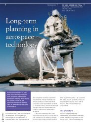
Recurring floods and ongoing traffic<br />
congestion have an adverse economic<br />
impact on Kuala Lumpur’s central business<br />
district in Malaysia. But now, a single<br />
solution to both problems is taking shape<br />
in the form of the world’s first <strong>dual</strong>-purpose<br />
tunnel capable of carrying vehicles and<br />
channelling storm water. The Stormwater<br />
Management and Road Tunnel (SMART)<br />
opening this spring, is the first of its kind in<br />
the world. Arthur Darby, Head of Tunnels<br />
at Mott MacDonald, tells the story behind<br />
this unique building project.<br />
© Mott Macdonald – Gamuda JV<br />
24 INGENIA ISSUE 30 MARCH 2007<br />
Major floods affecting Kuala<br />
Lumpur’s city centre occurred in<br />
1926 and 1971 but, after rapid<br />
urbanisation and expansion of<br />
the city since 1985, flooding has<br />
become an almost annual<br />
occurrence. Until 1985, the<br />
average annual flood in the<br />
Klang river was constant at<br />
about 148 m 3 /s. After 1985<br />
it increased rapidly so that by<br />
1995 the average annual flood<br />
was 440 m 3 /s. Kuala Lumpur’s<br />
urbanisation included the<br />
encroachment of infrastructure<br />
into the river channels, pushing<br />
flood river levels even higher.<br />
Since the major flood of<br />
1971, the Malaysian government<br />
has continuously monitored this<br />
situation. The Klang Basin Flood<br />
Mitigation Project has been<br />
developed and implemented<br />
incrementally involving a range<br />
of measures, including creating<br />
holding ponds and increasing<br />
river channel capacity. However,<br />
such measures alone would not<br />
be sufficient to prevent the<br />
flooding of the commercial<br />
centre of Kuala Lumpur.<br />
Detailed studies led to the<br />
INGENIA ISSUE 30 MARCH 2007 25
A DUAL - PURPOSE TUNNEL<br />
SUSTAINABILITY<br />
Flood Mitigation Project, the<br />
Malaysia Department of<br />
Irrigation, is developing an<br />
extensive flood warning system.<br />
The system will have rain gauges<br />
spread throughout the flood<br />
catchment area. These will feed<br />
information in real time to the<br />
Stormwater Control Centre,<br />
located at the point where water<br />
is diverted from the Klang River<br />
into a holding pond and into<br />
the tunnel. The computers<br />
in the Control Centre will use<br />
the rainfall and river level<br />
information, to predict probable<br />
flood magnitude which will<br />
lie in one of three ranges (see<br />
Figure 3).<br />
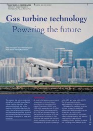
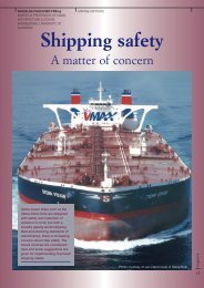
Figure 1. Stormwater Management and Road Tunnel showing the flood and tunnel areas, with current congestion and a<br />
cross section of the tunnel showing the two floors for cars with a channel underneath collecting low level flooding<br />
© Sepakat Setia Perunding (Sdn) Bhd<br />
concept of a tunnel for storm<br />
water storage but, at the design<br />
stage, the novel idea arose of<br />
also using it to tackle traffic<br />
congestion.<br />
TUNNEL VISION<br />
In 2001 the Government sought<br />
proposals from major<br />
development companies for<br />
a solution that would allow a<br />
typical flood of three to six<br />
hours’ duration to occur without<br />
inundating the city centre. A<br />
tunnel enabling floods to bypass<br />
the centre was one way of<br />
achieving this, providing it<br />
was coupled with temporary<br />
storage facilities to keep flows<br />
downstream of Kuala Lumpur<br />
within the capacity of the<br />
river channel.<br />
A group led by major<br />
Malaysian company Gamuda<br />
engaged SSP, a large Malaysian<br />
consultant engineering firm, and<br />
Mott MacDonald UK to develop<br />
26 INGENIA ISSUE 30 MARCH 2007<br />
proposals for a tunnel with<br />
holding ponds at upstream and<br />
downstream ends of the tunnel.<br />
For legal reasons, the tunnel had<br />
to run for most of its length<br />
under Government owned land<br />
– in practice under roads. Under<br />
competitive pressure to come<br />
up with the most cost-effective<br />
proposal, Gamuda considered<br />
whether the normally empty<br />
tunnel could also be used to<br />
carry some of the traffic that was<br />
otherwise in nose-to-tail jams on<br />
the roads above. The tunnel<br />
could be tolled, normal for<br />
expressways in Malaysia, and the<br />
income would reduce the<br />
requirement for Government<br />
funding.<br />
Plans were drawn up for a<br />
tunnel fitted with two road<br />
decks, one for traffic going north,<br />
and the other for traffic travelling<br />
south. Each deck would be wide<br />
enough for two traffic lanes<br />
(with a hard shoulder for<br />
breakdowns) and the headroom<br />
would be sufficient for cars and<br />
light vans only (see Figure 1). A<br />
two-deck, low-headroom tunnel<br />
was a unique idea and the<br />
concept of an alternate use of<br />
the same space by floods and<br />
traffic was also new.<br />
REQUIREMENTS FOR<br />
DUAL-PURPOSE USE<br />
For this concept to work, three<br />
special requirements had to be<br />
met. Safety – whilst in use as a<br />
highway it had to be certain that<br />
floodwater could not enter the<br />
highway space. Preparing the<br />
tunnel for floods – it had to be<br />
possible to predict floods in<br />
sufficient time to clear the<br />
tunnel and convert it to flood<br />
use before the flood peak<br />
arrived. Returning the tunnel to<br />
road use – after the flood had<br />
passed, the tunnel had to be<br />
able to be put back into<br />
highway service quickly in order<br />
to minimise both the loss of toll<br />
revenue and build up of<br />
congestion on alternative<br />
surface roads.<br />
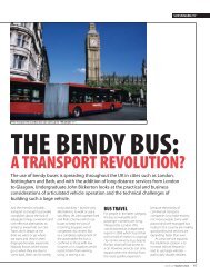
SAFETY<br />
The highway tunnel occupies<br />
the central, 3km long section<br />
of the 9.7km long flood tunnel.<br />
To ensure that flood water could<br />
not enter the highway space,<br />
service gates at both ends of<br />
the highway tunnel (see Figure 2)<br />
close the upper and lower road<br />
decks. A second barrier,<br />
the emergency gate, closes<br />
both road decks. In highway<br />
operation all these vertical lifting<br />
gates are closed and remain so<br />
under self-weight. Normally the<br />
holding pond will be empty so<br />
there will be no water pressure<br />
on the gates.<br />
PREPARING THE<br />
TUNNEL FOR FLOODS<br />
As part of its Klang River Basin<br />
Mode 1 – Flood. If the peak<br />
flow past the intake is predicted<br />
to be less than 70 m 3 /s, no water<br />
will be diverted into the holding<br />
pond and tunnel.<br />
Mode 2 – Flood. If the peak<br />
flow is forecast to be between<br />
70 and 150 m 3 /s, which occurs<br />
about ten times a year, radial<br />
gates will open enough to divert<br />
water into the holding pond and<br />
reduce river flow to 50 m 3 /s.<br />
Once the water in the holding<br />
pond reaches the crest of a<br />
bellmouth weir, it spills over<br />
into the tunnel. Flows of this<br />
magnitude are passed through<br />
the void under the lower road<br />
deck and do not require the<br />
tunnel to be taken out of<br />
traffic use.<br />
Mode 3a – Flood. If the peak<br />
flow is forecast to exceed<br />
150 m 3 /s (which occurs about<br />
once a year) then it will advise<br />
the Motorway Control Centre<br />
that it will be necessary to use<br />
one or both road decks for flood<br />
flow. Between 70 and 100<br />
minutes after the start of the<br />
storm, depending on its<br />
intensity, the radial gates will be<br />
lowered to divert water into the<br />
holding pond. Traffic will be<br />
stopped from entering the<br />
tunnel and the passage of<br />
vehicles already in the tunnel<br />
will be monitored on CCTV. The<br />
Motorway Control Centre will<br />
send a vehicle through the road<br />
Figure 2. how SMART's service gates will operate © Mott Macdonald<br />
Figure 3. A summary of operational modes used to manage stormwater in the city © Sepakat Setia Perunding (Sdn) Bhd<br />
INGENIA ISSUE 30 MARCH 2007 27
A DUAL - PURPOSE TUNNEL<br />
FEATURE<br />
SUSTAINABILITY<br />
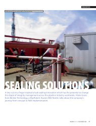
Two of the biggest tunnel boring machines ever seen in Asia are being used to<br />
create SMART. The tunneling machine bores a hole 13.2m diameter but the<br />
diameter inside the lining is 11.8m © Mott Macdonald<br />
tunnel to confirm that it is<br />
empty, and any broken down<br />
vehicles will be towed out.<br />
45 minutes is allowed for these<br />
activities. The gates at the ends<br />
of the road deck will be lifted<br />
while the tunnel is still dry.<br />
Between 50 and 60 minutes<br />
after water has first been<br />
diverted into the holding pond,<br />
it will spill over the bell mouth<br />
and into the tunnel.<br />
Mode 3b – Flood with delayed<br />
opening of tunnel. If it takes<br />
longer than 45 minutes to clear<br />
the tunnel, water will continue<br />
to fill the holding pond and run<br />
through the tunnel and under<br />
the lower road deck. Water<br />
pressure will build up on the<br />
emergency gates at both ends<br />
of the highway decks. Once the<br />
road decks are eventually cleared<br />
the gates can be opened.<br />
28 INGENIA ISSUE 30 MARCH 2007<br />
An abrupt transition from open<br />
channel water flow, with air<br />
between the water surface and<br />
the tunnel crown, to pressurised<br />
‘pipe full’ flow could generate<br />
high transient pressures capable<br />
of damaging the structure.<br />
Advanced numerical modelling<br />
was thus undertaken to<br />
determine the safe opening<br />
sequence for the gates. It was<br />
found necessary to provide<br />
surge pressure relief at the four<br />
ventilation shafts along the<br />
tunnel, as well as providing a<br />
relief shaft downstream of the<br />
road decks.<br />
RETURNING THE<br />
TUNNEL TO ROAD USE<br />
Once the flood has passed, the<br />
diversion gates are raised so that<br />
no more water enters the<br />
holding pond. It will take about<br />
three hours for most of the<br />
water to drain out of the tunnel<br />
under gravity. Pumps at the<br />
downstream end of the water<br />
tunnel can fully empty the road<br />
section in a further five hours.<br />
The ventilation system will be<br />
employed to assist drying.<br />
Minimal work is anticipated<br />
to return the tunnel to service.<br />
A trash barrier will have<br />
prevented floating debris<br />
entering the tunnel. All fittings<br />
within the tunnel have been<br />
designed to withstand a water<br />
velocity of 5 m/s, and the<br />
electrical fittings have been<br />
specified to IP68 to withstand<br />
continuous immersion. The<br />
emergency telephones are<br />
located in escape staircases,<br />
connecting the decks, which<br />
will be closed off with watertight<br />
doors. The holding pond at<br />
the upstream end will act as a<br />
settling pond to remove sand<br />
and grit, and the velocity within<br />
the tunnel is sufficient to ensure<br />
remaining fine particles stay<br />
in suspension and are carried<br />
through to the attenuation<br />
pond. The road decks will be<br />
washed down to remove a<br />
possible film of fine sludge<br />
and then sprayed with an<br />
anti-bacteriological solution to<br />
eliminate odour.<br />
Overall, a period of 48 hours<br />
has been allowed to bring the<br />
tunnel back into service after a<br />
flood. A flood requiring use of<br />
the tunnel will only occur on<br />
average about once a year, so<br />
interference with the road<br />
operation will be tolerable.<br />
A VENTILATION<br />
SYSTEM THAT WILL<br />
SURVIVE FLOODING<br />
While it was possible to specify<br />
that the tunnel lighting and<br />
CCTV equipment should be<br />
waterproof, this was not feasible<br />
for the ventilation fans.<br />
Consequently, they were located<br />
in four shafts at 1km intervals.<br />
In extreme situations, the water<br />
level in the shafts could rise to<br />
the level of the fans, so they will<br />
be protected behind watertight<br />
doors that are closed before the<br />
gates are raised.<br />
The ventilation fans can inject<br />
105 m 3 /s of fresh air into the<br />
road decks at the shafts through<br />
Saccardo nozzles at up to 20 m/s.<br />
In an emergency situation, after<br />
a multiple vehicle fire for<br />
example, passengers would be<br />
instructed by the public address<br />
system to leave their cars and<br />
walk to the nearest escape.<br />
Because the lower road deck has<br />
only three metres of headroom,<br />
there was concern that the high<br />
air velocities from the nozzles<br />
might discourage people<br />
from reaching the ventilation<br />
shafts, which contain emergency<br />
escape stairs. A three<br />
dimensional model that could<br />
simulate turbulence was built,<br />
using computational fluid<br />
dynamics and showed that very<br />
high velocities were restricted to<br />
the top of the tunnel above<br />
head level.<br />
GEOLOGY AND<br />
TUNNEL ALIGNMENT<br />
The geology, along the tunnel<br />
route, consists of alluvium<br />
overlying dolomitic limestone<br />
in which dissolution by water<br />
has created many cavities filled<br />
with soft material or water. As<br />
such, the surface of this karstic<br />
limestone is extremely irregular.<br />
Ideally, from a construction<br />
point of view, the tunnel would<br />
have been aligned deep enough<br />
to remain wholly within the<br />
limestone. However, the elevation<br />
of the tunnel was fixed by hydraulic<br />
considerations at both ends, and<br />
while about 70% of the tunnel<br />
was excavated in rock there were<br />
many places, particularly towards<br />
the northern end, where the<br />
upper part of the tunnel was<br />
located in soft alluvium or ground<br />
disturbed by tin mining. Such<br />
variation between hard rock and<br />
very soft waterlogged soil made<br />
for difficult tunnelling, particularly<br />
below a busy city where ground<br />
settlement had to be controlled<br />
to prevent damage to existing<br />
infrastructure.<br />
The tunnelling principle: (1) behind the cutting wheel with muck bucket lips and cutter tools is a steel<br />
cylinder, the shield (2). It is within the protection of this shield that the tunnel is excavated. The space in<br />
front of the pressure buckhead (3) is filled with a bentonite suspension which seals the existing soil. The<br />
pressure necessary to support the tunnel face is produced by means of a compressed air cushion (4) in<br />
the excavation chamber, which is divided by a submerged wall (5). The excavated soil is pumped into the<br />
slurry line (6) together with the suspension. Large rocks are broken down by a stone crusher (7). The<br />
suspension is supplied via the feed line (8). Protected by the shield, the reinforced concrete segments (9)<br />
are installed by an erector (10). To continue the advance, the machine presses against each previously<br />
installed segmental ring with hydraulic thrust cylinders (11). The annular gap between the segmental ring<br />
and the ground is continuously grouted with mortar as the machine advances. All operations are<br />
controlled from the control panel.<br />
Figure 4. A numbered cross section of the Herrenknecht mixshield machine © Herrenknecht<br />
TUNNEL BORING<br />
MACHINES<br />
Simple tunnel boring machines,<br />
of the kind used in clay under<br />
London, follow the 19th century<br />
concept of a rotating cutter<br />
head on which are mounted<br />
picks and a cylindrical shield<br />
to support the ground where<br />
necessary. This concept would<br />
not have worked in Kuala<br />
Lumpur, because water and<br />
loose soil would have poured<br />
uncontrollably past the cutter<br />
head into the tunnel. Therefore,<br />
it was necessary to use a more<br />
modern and more complex<br />
design of machine with a<br />
bulkhead behind the rotating<br />
cutter head closing off the<br />
tunnel face. This enables the<br />
water and soil to be kept at a<br />
pressure sufficient to prevent<br />
movement of ground towards<br />
the tunnel face.<br />
In the type of machine<br />
selected, spoil is removed from<br />
the tunnel face in a bentonite<br />
slurry which is pumped to the<br />
surface, passed through a<br />
separation plant utilising<br />
cyclones to separate the spoil,<br />
and then the cleaned slurry is<br />
returned to the tunnel face.<br />
A feature of the Herrenknecht<br />
mixshield machines that were<br />
used is that a compressed<br />
air bubble (see 4, Figure 4) is<br />
maintained in a chamber<br />
behind a bulkhead behind the<br />
cutterhead. If the cutterhead<br />
suddenly encounters a soil-filled<br />
cavity, as happens in karstic<br />
limestone, the magnitude of any<br />
pressure drop in the bentonite is<br />
reduced by the bubble<br />
expanding.<br />
Very soft soil, below the<br />
invert level of the machine, was<br />
grouted from the surface to<br />
ensure that the machine would<br />
not sink under its own weight.<br />
Movement of the ground<br />
surface was monitored by<br />
precise levelling, and ground<br />
water levels were monitored,<br />
as falls in groundwater level<br />
could lead to settlement in the<br />
soft soils.<br />
In practice, settlements<br />
caused by machine tunnelling<br />
were generally very small (a<br />
matter of millimetres), but very<br />
occasionally combinations of<br />
ground and machine operation<br />
led to local over-excavation. The<br />
diameter of the bore is 13.2m,<br />
the height of a five storey<br />
building. This was, at the time<br />
of ordering the machine, one<br />
of the largest in the world.<br />
INGENIA ISSUE 30 MARCH 2007<br />
29
A DUAL - PURPOSE TUNNEL<br />
PROGRAMME<br />
TO COMPLETION<br />
The lower road deck has been<br />
pressure tested by building a<br />
bulkhead below the lower deck<br />
and filling the invert with water.<br />
Static testing of the whole<br />
tunnel by this method is not<br />
feasible, and the performance<br />
of the structure and systems<br />
will be carefully monitored<br />
during the first floods that pass<br />
through. It is expected that<br />
operating rules will require<br />
optimisation in the light of<br />
experience.<br />
Opening of the highway<br />
tunnel is scheduled at the end<br />
of March 2007. At that time, the<br />
northernmost section of the<br />
flood tunnel will still be under<br />
construction and the opening<br />
of the flood tunnel, will follow<br />
at the end of June 2007. Kuala<br />
Lumpur will then be able to<br />
enjoy the full benefits of this<br />
innovative engineering.<br />
Breakthrough on the north side of the tunnel. The overall length river to river is<br />
11.5km which includes both bored and cut and cover tunnel. The bored tunnel is<br />
9.7km long of which the central 3km also serves as a road tunnel<br />
© Mott Macdonald – Gamuda JV<br />
Entrance to road tunnel visible behind toll plaza – with Petronas twin towers in central Kuala Lumpur in background<br />
© Mott Macdonald<br />
BIOGRAPHY – ARTHUR DARBY<br />
Arthur Darby is a graduate in engineering from Cambridge University and has a Master’s degree in soil mechanics from Imperial<br />
College. He has wide experience, in the UK and internationally, of management roles on both water and tunnel projects including: the<br />
Channel Tunnel and Heathrow Terminal 5. He is a Divisional Director of Mott MacDonald’s Metro<br />
and Civil Division, and Head of Tunnels.<br />
30 INGENIA ISSUE 30 MARCH 2007


![[322/03] Francke - Ingenia](https://img.yumpu.com/23411337/1/184x260/322-03-francke-ingenia.jpg?quality=85)