Errata - Federal Highway Administration - U.S. Department of ...
Errata - Federal Highway Administration - U.S. Department of ...
Errata - Federal Highway Administration - U.S. Department of ...

You also want an ePaper? Increase the reach of your titles
YUMPU automatically turns print PDFs into web optimized ePapers that Google loves.
<strong>Errata</strong><br />
Date: October 22, 2013<br />
Issuing Office:<br />
Address:<br />
Name <strong>of</strong> Document:<br />
FHWA Publication No.:<br />
<strong>Federal</strong> <strong>Highway</strong> <strong>Administration</strong>—Office <strong>of</strong> Research,<br />
Development, and Technology: Infrastructure Research and<br />
Development<br />
Turner-Fairbank <strong>Highway</strong> Research Center, 6300 Georgetown<br />
Pike, McLean, VA 22101<br />
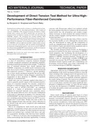
Guidelines for Sampling, Assessing, and Restoring Defective<br />
Grout in Prestressed Concrete Bridge Post-Tensioning Ducts<br />
FHWA-HRT-13-028<br />
The following changes were made to the document after publication:<br />
Location Incorrect Values Corrected Values<br />
Table 32 on page 90 CD3 0.08 < Cl − ≤ 0.20 b CD3 0.2 < Cl − ≤ 0.50 b<br />
Table 33 on page 91 CD3 0.02 < Cl − ≤ 0.50 CD3 0.2 < Cl − ≤ 0.50
Guidelines for Sampling, Assessing, and<br />
Restoring Defective Grout in Prestressed<br />
Concrete Bridge Post-Tensioning Ducts<br />
Publication No. FHWA-HRT-13-028 october 2013<br />
Research, Development, and Technology<br />
Turner-Fairbank <strong>Highway</strong> Research Center<br />
6300 Georgetown Pike<br />
McLean, VA 22101-2296
FOREWORD<br />
Post-tensioned (PT) tendons have been widely utilized in concrete bridges in the United States.<br />
The advantages <strong>of</strong> PT bridges compared to bridges constructed using conventional reinforcement<br />
include greater span length, structural efficiency, reduced materials, and a more streamlined<br />
appearance. However, PT tendons can be susceptible to corrosion and ultimately failure if<br />
physical deficiencies (PDs) or chemical deficiencies (CDs) are present. Examples <strong>of</strong> PDs include<br />
separation, segregation, presence <strong>of</strong> s<strong>of</strong>t material, and free water, while an example <strong>of</strong> a CD<br />
includes concentrations <strong>of</strong> chloride that exceed the allowable limit as specified by the American<br />
Association <strong>of</strong> State <strong>Highway</strong> and Transportation Officials and other specifications. The failure<br />
<strong>of</strong> a few tendons can compromise overall structural integrity.<br />
Inspections <strong>of</strong> bridge PT tendons have revealed both PDs and CDs as well as strand tendon<br />
failures caused by corrosion have been reported. This study was performed to provide bridge<br />
owners with a practical protocol for inspecting, sampling, analyzing, evaluating, and responding<br />
to bridge grout concerns.<br />
Jorge E. Pagán-Ortiz<br />
Director, Office <strong>of</strong> Infrastructure<br />
Research and Development<br />
Notice<br />
This document is disseminated under the sponsorship <strong>of</strong> the U.S. <strong>Department</strong> <strong>of</strong> Transportation<br />
in the interest <strong>of</strong> information exchange. The U.S. Government assumes no liability for the use <strong>of</strong><br />
the information contained in this document. This report does not constitute a standard,<br />
specification, or regulation.<br />
The U.S. Government does not endorse products or manufacturers. Trademarks or<br />
manufacturers’ names appear in this report only because they are considered essential to the<br />
objective <strong>of</strong> the document.<br />
Quality Assurance Statement<br />
The <strong>Federal</strong> <strong>Highway</strong> <strong>Administration</strong> (FHWA) provides high-quality information to serve<br />
Government, industry, and the public in a manner that promotes public understanding. Standards<br />
and policies are used to ensure and maximize the quality, objectivity, utility, and integrity <strong>of</strong> its<br />
information. FHWA periodically reviews quality issues and adjusts its programs and processes to<br />
ensure continuous quality improvement.
TECHNICAL REPORT DOCUMENTATION PAGE<br />
1. Report No.<br />
2. Government Accession No. 3. Recipient’s Catalog No.<br />
FHWA-HRT-13-028<br />
4. Title and Subtitle<br />
5. Report Date<br />
Guidelines for Sampling, Assessing, and Restoring Defective Grout<br />
in Prestressed Concrete Bridge Post-Tensioning Ducts<br />
October 2013<br />
6. Performing Organization Code<br />
7. Author(s)<br />
Teddy S. Theryo, William H. Hartt, and Piotr Paczkowski<br />
9. Performing Organization Name and Address<br />
Parsons Brinckerh<strong>of</strong>f, Inc.<br />
2202 North West Shore Blvd. Suite 300<br />
Tampa, FL 33607<br />
William H. Hartt, PhD, PE, F-NACE<br />
Consulting Engineer<br />
20914 Morada Court<br />
Boca Raton, FL 33433<br />
12. Sponsoring Agency Name and Address<br />
Office <strong>of</strong> Infrastructure Research and Development<br />
<strong>Federal</strong> <strong>Highway</strong> <strong>Administration</strong><br />
6300 Georgetown Pike<br />
8. Performing Organization Report No.<br />
10. Work Unit No.<br />
11. Contract or Grant No.<br />
13. Type <strong>of</strong> Report and Period Covered<br />
Final Report<br />
14. Sponsoring Agency Code<br />
McLean, VA 22101-2296<br />
15. Supplementary Notes<br />
The Contracting Officer’s Technical Representatives (COTRs) were Y.P. Virmani and H. Ghasemi, HRDI-60. An<br />
expert task group comprised <strong>of</strong> members from industry, academia, State transportation departments, and the posttensioning<br />
industry provided valuable technical input and guidance. This study was part <strong>of</strong> the Long-Term Bridge<br />
Performance Program.<br />
16. Abstract<br />
A significant proportion <strong>of</strong> the U.S. bridge inventory is based on bonded post-tensioned (PT) concrete construction. An<br />
important aspect <strong>of</strong> maintaining corrosion protection <strong>of</strong> these PT systems is assuring that tendon ducts are properly grouted<br />
with an acceptable material. Grout is a cementitious material typically used to provide corrosion protection to the strands<br />
used in PT concrete bridges. However, inspections have revealed fractured strands and, in some cases, failed tendons as a<br />
consequence <strong>of</strong> corrosion, even with the newer prepackaged, preapproved thixotropic grouts. Studies to-date have attributed<br />
this corrosion to physical or chemical grout deficiencies (or both), the former consisting <strong>of</strong> air voids, free water, and<br />
unhardened, segregated, or separated grout and the latter <strong>of</strong> chloride concentration in excess <strong>of</strong> what is specified by the<br />
American Association <strong>of</strong> State <strong>Highway</strong> and Transportation Officials and other specifications. Based on collected<br />
information and data analysis, State transportation departments can evaluate if grout deficiencies are present in the tendons<br />
<strong>of</strong> their PT bridges and determine the significance <strong>of</strong> any deficiencies. Durability concerns associated with PT tendons<br />
were raised as early as 1999 when tendon failures were seen in some PT bridges as a result <strong>of</strong> strand corrosion due to the<br />
collection <strong>of</strong> bleed water in grout voids at tendon pr<strong>of</strong>ile locations like anchorages and crest areas. While the development<br />
<strong>of</strong> prepackaged thixotropic grout was thought to provide a solution to the bleed water problem, corrosion-caused tendon<br />
failures on relatively new PT bridges have occurred, and forensic studies have revealed separation and segregation <strong>of</strong> grout<br />
materials as well as the presence <strong>of</strong> s<strong>of</strong>t material, free water, and high chloride and sulfate content. (1–3) Consequently, it<br />
has become important to examine the overall quality <strong>of</strong> materials and construction for some in-place grouts in existing PT<br />
bridges. The purpose <strong>of</strong> this study is to provide State transportation departments with guidance regarding tendon inspection,<br />
grout sampling, data analysis, and interpretation.<br />
17. Key Words<br />
Post-tensioned tendons, Bridges, Corrosion, Grout,<br />
Chlorides, Grout defects, Inspection, Sampling<br />
19. Security Classif. (<strong>of</strong> this report)<br />
Unclassified<br />
Form DOT F 1700.7 (8-72)<br />
18. Distribution Statement<br />
No restrictions. This document is available to the public through the<br />
National Technical Information Service, Springfield, VA 22161.<br />
20. Security Classif. (<strong>of</strong> this page)<br />
Unclassified<br />
21. No <strong>of</strong> Pages 22. Price<br />
130<br />
Reproduction <strong>of</strong> completed pages authorized
TABLE OF CONTENTS<br />
CHAPTER 1. BACKGROUND ................................................................................................... 1<br />
CHAPTER 2. OBJECTIVES OF INSPECTION ...................................................................... 3<br />
CHAPTER 3. PT SYSTEMS ....................................................................................................... 5<br />
BACKGROUND ..................................................................................................................... 5<br />
PT TENDON TYPES ............................................................................................................. 7<br />
PT BRIDGE TYPES ............................................................................................................... 8<br />
Cast-in-Place (CIP) PT Box Girder Bridges on False Works ............................................. 8<br />
CIP PT Concrete Slab and T-Girder Bridges .................................................................... 10<br />
CIP Segmental Balanced Cantilever Bridge ..................................................................... 11<br />
Precast Spliced I-Girder Bridge ........................................................................................ 14<br />
Precast Spliced U-Girder Bridge ...................................................................................... 15<br />
Precast Segmental Balanced Cantilever Bridge ................................................................ 17<br />
Precast Segmental Span-by-Span Bridge.......................................................................... 18<br />
Concrete Cable-Supported Bridge .................................................................................... 21<br />
Special PT Concrete Substructures ................................................................................... 22<br />
CHAPTER 4. GROUT DEFICIENCIES ................................................................................. 25<br />
BACKGROUND ................................................................................................................... 25<br />
Cl − Threshold .................................................................................................................... 25<br />
Previous Investigations ..................................................................................................... 27<br />
Deficiencies....................................................................................................................... 32<br />
CHAPTER 5. MINIMUM NUMBER OF TEST SAMPLES ................................................. 33<br />
GENERAL ............................................................................................................................. 33<br />
INSPECTION OPTIONS ..................................................................................................... 34<br />
INSPECTING CL − CONTENT (OPTION 1) .................................................................... 34<br />
Project with Complete Grouting Records ......................................................................... 34<br />
Project with Incomplete or No Grouting Records ............................................................ 35<br />
INSPECTING ALL GROUT DEFICIENCIES (OPTION 2) .......................................... 35<br />
Probability <strong>of</strong> Defect Indicator ......................................................................................... 37<br />
Consequence <strong>of</strong> Failure Indicator ..................................................................................... 39<br />
Risk Level ......................................................................................................................... 41<br />
Acceptable Fraction <strong>of</strong> Tendons with Undetected Deficient Grout .................................. 41<br />
Minimum Number <strong>of</strong> Inspected Tendons ......................................................................... 41<br />
Sampling Procedure Summary ......................................................................................... 46<br />
EXAMPLES .......................................................................................................................... 47<br />
Typical Balanced Cantilever Bridge ................................................................................. 47<br />
Typical Spliced Girder Bridge .......................................................................................... 53<br />
Typical Span-by-Span Segmental Bridge ......................................................................... 56<br />
Typical PT Bridge with Draped Tendons ......................................................................... 58<br />
iii
CHAPTER 6. GROUT SAMPLING AND TEST METHODS .............................................. 61<br />
GENERAL CONSIDERATIONS ....................................................................................... 61<br />
Sample Size ....................................................................................................................... 66<br />
Analyses ............................................................................................................................ 66<br />
Tools, Equipment, and Instrumentation ............................................................................ 68<br />
Reporting........................................................................................................................... 69<br />
CHAPTER 7. STRATEGIC SAMPLING LOCATIONS ....................................................... 73<br />
BACKGROUND ................................................................................................................... 73<br />
BALANCED CANTILEVER BRIDGE .............................................................................. 75<br />
Continuity Tendon (Internal Tendon in the Bottom Flange) ............................................ 75<br />
Cantilever Tendon (Internal) ............................................................................................. 77<br />
PRECAST SEGMENTAL SPAN-BY-SPAN BRIDGE .................................................... 77<br />
CIP PT BRIDGE ................................................................................................................... 78<br />
SPLICED GIRDER BRIDGE ............................................................................................. 78<br />
CHAPTER 8. RESTORATION METHODS ........................................................................... 81<br />
GENERAL ............................................................................................................................. 81<br />
TEMPORARY RESTORATION ........................................................................................ 82<br />
External Tendon ................................................................................................................ 82<br />
Internal Tendon ................................................................................................................. 83<br />
PERMANENT RESTORATION ........................................................................................ 83<br />
External Tendon ................................................................................................................ 83<br />
Internal Tendon ................................................................................................................. 84<br />
Grout Cap .......................................................................................................................... 85<br />
RESTORATION MATERIAL ............................................................................................ 87<br />
CHAPTER 9. INTERPRETATION OF RESULTS AND COURSES OF ACTION ........... 89<br />
BACKGROUND ................................................................................................................... 89<br />
Evaluation Approach and Interpretation ........................................................................... 89<br />
Examples ........................................................................................................................... 92<br />
Reinspections, Non-Destructive Testing (NDT), and Monitoring.................................... 94<br />
APPENDIX A. TYPICAL BALANCED CANTILEVER BRIDGE PLANS ........................ 97<br />
APPENDIX B. TYPICAL SPLICED GIRDER BRIDGE PLANS ...................................... 109<br />
REFERENCES .......................................................................................................................... 119<br />
iv
LIST OF FIGURES<br />
Figure 1. Illustration. Basic PT anchorage system ......................................................................... 5<br />
Figure 2. Photo. Old generation <strong>of</strong> PT anchorage system .............................................................. 6<br />
Figure 3. Photo. New generation <strong>of</strong> PT anchorage system ............................................................. 6<br />
Figure 4. Illustration. Internal tendon ............................................................................................. 7<br />
Figure 5. Illustration. External tendon ............................................................................................ 7<br />
Figure 6. Photo. External tendons at deviator ................................................................................. 8<br />
Figure 7. Photo. CIP concrete box girder bridge on false works .................................................... 9<br />
Figure 8. Illustration. CIP bridge typical tendon layout ................................................................. 9<br />
Figure 9. Photo. Blister at the top flange ...................................................................................... 10<br />
Figure 10. Illustration. Transverse internal tendon in the diaphragm ........................................... 10<br />
Figure 11. Photo. CIP PT concrete slab bridge ............................................................................. 11<br />
Figure 12. Illustration. PT slab bridge typical tendon layout ....................................................... 11<br />
Figure 13. Photo. CIP segmental balanced cantilever bridge ....................................................... 12<br />
Figure 14. Photo. CIP balanced cantilever bridge during construction using form traveler ........ 13<br />
Figure 15. Photo. Typical bottom flange blister ........................................................................... 13<br />
Figure 16. Illustration. Typical vertical tendon in the web ........................................................... 14<br />
Figure 17. Illustration. Typical vertical tendon in the diaphragm ................................................ 14<br />
Figure 18. Photo. Precast spliced girder bridge ............................................................................ 15<br />
Figure 19. Photo. Precast spliced girder bridge during erection ................................................... 15<br />
Figure 20. Photo. Precast spliced U-girder bridge during erection ............................................... 16<br />
Figure 21. Photo. Precast U-girder supported on temporary false work ...................................... 17<br />
Figure 22. Photo. Precast segmental balanced cantilever bridge erection using a segment<br />
lifter ............................................................................................................................................... 18<br />
Figure 23. Photo. Precast segmental span-by-span erection using an overhead gantry ............... 19<br />
Figure 24. Illustration. Typical precast segmental span-by-span external PT tendon layout ....... 20<br />
Figure 25. Photo. Precast segmental cable stayed bridge ............................................................. 22<br />
Figure 26. Illustration. Cross section <strong>of</strong> precast segmental columns ............................................ 23<br />
Figure 27. Photo. PT straddle bent during construction ............................................................... 23<br />
Figure 28. Photo. Failed tendon cross section .............................................................................. 27<br />
Figure 29. Photo. Longitudinal section <strong>of</strong> a tendon section with types 1–3 grout identified ....... 28<br />
Figure 30. Photo. Opened tendon end showing predominantly type 3 grout and strand<br />
corrosion products ......................................................................................................................... 29<br />
Figure 31. Photo. Opened tendon end showing types 3 and 1 grout and strand corrosion<br />
products ......................................................................................................................................... 29<br />
Figure 32. Photo. Opened tendon end revealing type 4 grout (bottom half), type 1 grout<br />
(center region), and strand corrosion products (upper region) ..................................................... 30<br />
Figure 33. Photo. Opened anchorage on the Carbon Plant Road bridge over IH-37 .................... 30<br />
Figure 34. Equation. Reaction <strong>of</strong> the ferrous ion with water and sulfate ion to yield<br />
ferrous hydroxide and sulfuric acid .............................................................................................. 31<br />
Figure 35. Flowchart. Inspection options ..................................................................................... 34<br />
Figure 36. Flowchart. Grout inspection processes ........................................................................ 36<br />
Figure 37. Graph. Risk matrix ...................................................................................................... 37<br />
Figure 38. Equation. Overall probability <strong>of</strong> defect indicator ........................................................ 39<br />
Figure 39. Equation. Overall consequence <strong>of</strong> failure indicator .................................................... 40<br />
v
Figure 40. Equation. Risk ............................................................................................................. 41<br />
Figure 41. Equation. Probability mass function for hypergeometric distribution ........................ 42<br />
Figure 42. Graph. Example <strong>of</strong> PMF for hypergeometric distribution .......................................... 42<br />
Figure 43. Equation. CDF ............................................................................................................. 42<br />
Figure 44. Graph. Example <strong>of</strong> CDF for a hypergeometric distribution ........................................ 43<br />
Figure 45. Graph. Minimum number <strong>of</strong> tendons required to detect at least one tendon with<br />
deficient grout assuming 5 percent <strong>of</strong> the samples are defective.................................................. 44<br />
Figure 46. Graph. Minimum number <strong>of</strong> tendons required to detect at least one tendon with<br />
deficient grout assuming 10 percent <strong>of</strong> the samples are defective................................................ 45<br />
Figure 47. Graph. Minimum number <strong>of</strong> tendons required to detect at least one tendon with<br />
deficient grout assuming 20 percent <strong>of</strong> the samples are defective................................................ 45<br />
Figure 48. Graph. Minimum number <strong>of</strong> tendons required to detect at least one tendon with<br />
deficient grout assuming 30 percent <strong>of</strong> the samples are defective................................................ 46<br />
Figure 49. Graph. Balanced cantilever bridge—tendon risk categories ....................................... 48<br />
Figure 50. Graph. Spliced girder bridge—tendon risk categories ................................................ 54<br />
Figure 51. Graph. Span-by-span segmental bridge—tendon risk categories................................ 58<br />
Figure 52. Graph. PT bridge—tendon risk categories .................................................................. 60<br />
Figure 53. Photo. Dial gauge used to determine the depth <strong>of</strong> a grout air void ............................. 61<br />
Figure 54. Photo. Grout sample acquisition at an opened internal tendon end cap by light<br />
chipping......................................................................................................................................... 62<br />
Figure 55. Photo. Concrete excavation to expose an internal tendon ........................................... 63<br />
Figure 56. Photo. Internal tendon access at an intermediate location by drilling ......................... 64<br />
Figure 57. Photo. Access hole in an internal tendon at an intermediate location revealing<br />
strand and grout............................................................................................................................. 64<br />
Figure 58. Photo. View <strong>of</strong> a duct interior revealing a channel air void ........................................ 65<br />
Figure 59. Illustration. Bridge representation used to identify grout sampling locations............. 69<br />
Figure 60. Illustration. Chart used to record the location and information for individual<br />
grout samples ................................................................................................................................ 70<br />
Figure 61. Illustration. Chart used to record and present analysis results for individual<br />
grout samples ................................................................................................................................ 71<br />
Figure 62. Photo. Removing a permanent grout cap .................................................................... 73<br />
Figure 63. Photo. Exposed anchor head after grout sampling ...................................................... 74<br />
Figure 64. Photo. Locating internal tendons in the web wall using GPR ..................................... 75<br />
Figure 65. Photo. Partial removal <strong>of</strong> a grout cap .......................................................................... 76<br />
Figure 66. Illustration. Typical cantilever tendon inspection point locations............................... 76<br />
Figure 67. Illustration. Typical continuity tendon inspection point locations .............................. 77<br />
Figure 68. Illustration. Typical span-by-span bridge external tendon inspection point<br />
locations ........................................................................................................................................ 78<br />
Figure 69. Illustration. CIP PT bridge inspection point locations ................................................ 78<br />
Figure 70. Illustration. Spliced bulb-tee girder bridge inspection point locations........................ 79<br />
Figure 71. Photo. Spliced bulb-tee girder bridge CIP joint detail ................................................ 79<br />
Figure 72. Illustration. Spliced U-girder bridge inspection locations ........................................... 80<br />
Figure 73. Photo. Temporary restoration <strong>of</strong> an external tendon ................................................... 82<br />
Figure 74. Photo. Permanent restoration <strong>of</strong> an external tendon using heat shrink sleeve ............ 83<br />
Figure 75. Illustration. Permanent restoration <strong>of</strong> an internal tendon duct .................................... 84<br />
Figure 76. Photo. Completed restoration <strong>of</strong> a partially cut grout cap prior to coating ................. 85<br />
vi
Figure 77. Photo. Applying elastomeric coating over a grout cap ................................................ 86<br />
Figure 78. Photo. Completed permanent restoration <strong>of</strong> a grout cap ............................................. 86<br />
Figure 79. Flowchart. Inspection, sampling, evaluation, and actions for levels 1 and 2<br />
inspections for option 1 ................................................................................................................. 92<br />
Figure 80. Flowchart. Inspection, sampling, evaluation, and actions for levels 1 and 2<br />
inspections for option 2 ................................................................................................................. 92<br />
Figure 81. Illustration. Segment layout—part 1 ........................................................................... 97<br />
Figure 82. Illustration. Segment layout—part 2 ........................................................................... 98<br />
Figure 83. Illustration. Bulkhead details ....................................................................................... 99<br />
Figure 84. Illustration. Longitudinal PT layout—part 1 ............................................................. 100<br />
Figure 85. Illustration. Longitudinal PT layout—part 2 ............................................................. 101<br />
Figure 86. Illustration. Longitudinal PT layout—part 3 ............................................................. 102<br />
Figure 87. Illustration. Longitudinal PT layout—part 4 ............................................................. 103<br />
Figure 88. Illustration. Longitudinal PT layout—part 5 ............................................................. 104<br />
Figure 89. Illustration. Longitudinal PT layout—part 6 ............................................................. 105<br />
Figure 90. Illustration. Longitudinal PT layout—part 7 ............................................................. 106<br />
Figure 91. Illustration. Longitudinal PT layout—part 8 ............................................................. 107<br />
Figure 92. Illustration. Plan and elevation—main channel unit ................................................. 109<br />
Figure 93. Illustration. Bridge section ........................................................................................ 110<br />
Figure 94. Illustration. Pier cap PT details ................................................................................. 111<br />
Figure 95. Illustration. Tendon pr<strong>of</strong>ile—main channel unit ....................................................... 112<br />
Figure 96. Illustration. Modified Florida bulb-T78 beam end segment ..................................... 113<br />
Figure 97. Illustration. Modified Florida bulb-T78 beam haunch segment ................................ 114<br />
Figure 98. Illustration. Modified Florida bulb-T78 beam drop-in segment ............................... 115<br />
Figure 99. Illustration. Modified Florida bulb-T78 beam end block detail ................................ 116<br />
Figure 100. Illustration. Typical sections—haunch segment ...................................................... 117<br />
vii
LIST OF TABLES<br />
Table 1. Bridge condition—probability <strong>of</strong> defect indicator.......................................................... 37<br />
Table 2. Construction and inspection records—probability <strong>of</strong> defect indicator ........................... 37<br />
Table 3. Visual evaluation—probability <strong>of</strong> defect indicators ....................................................... 38<br />
Table 4. Tendon geometry and length—probability <strong>of</strong> defect indicators ..................................... 38<br />
Table 5. Weight factors for probability <strong>of</strong> defect indicator .......................................................... 39<br />
Table 6. Consequence <strong>of</strong> failure indicator versus cost <strong>of</strong> repair or tendon replacement .............. 39<br />
Table 7. Consequence <strong>of</strong> failure indicator versus element/tendon redundancy ............................ 40<br />
Table 8. Consequence <strong>of</strong> failure indicator versus bridge importance ........................................... 40<br />
Table 9. Weight factors for consequence <strong>of</strong> failure indicator ....................................................... 41<br />
Table 10. Acceptable fractions <strong>of</strong> undetected tendons with deficient grout ................................. 41<br />
Table 11. Minimum number <strong>of</strong> tendons required to detect at least one tendon with<br />
deficient grout (75 percent confidence) ........................................................................................ 44<br />
Table 12. Minimum number <strong>of</strong> tendons required to detect at least one tendon with<br />
deficient grout (95 percent confidence) ........................................................................................ 44<br />
Table 13. Balanced cantilever bridge—probability <strong>of</strong> defect indicator ........................................ 48<br />
Table 14. Balanced cantilever bridge—consequence <strong>of</strong> failure indicator .................................... 48<br />
Table 15. Balanced cantilever bridge—minimum recommended number <strong>of</strong> tendons for<br />
inspection ...................................................................................................................................... 49<br />
Table 16. List <strong>of</strong> continuity tendons ............................................................................................. 50<br />
Table 17. List <strong>of</strong> external draped tendons ..................................................................................... 51<br />
Table 18. List <strong>of</strong> selected transverse tendons ............................................................................... 51<br />
Table 19. List <strong>of</strong> cantilever tendons .............................................................................................. 52<br />
Table 20. Spliced girder bridge—probability <strong>of</strong> defect indicator ................................................. 54<br />
Table 21. Spliced girder bridge—consequence <strong>of</strong> failure indicator ............................................. 54<br />
Table 22. Spliced girder bridge—minimum recommended number <strong>of</strong> tendons for inspection ... 55<br />
Table 23. List <strong>of</strong> longitudinal draped tendons .............................................................................. 55<br />
Table 24. List <strong>of</strong> diaphragm tendons ............................................................................................ 56<br />
Table 25. List <strong>of</strong> pier cap tendons ................................................................................................. 56<br />
Table 26. Span-by-span segmental bridge—probability <strong>of</strong> defect indicator ................................ 57<br />
Table 27. Span-by-span segmental bridge—consequence <strong>of</strong> failure indicator............................. 57<br />
Table 28. Span-by-span segmental bridge—minimum recommended number <strong>of</strong> tendons<br />
for inspection ................................................................................................................................ 58<br />
Table 29. PT bridge—probability <strong>of</strong> defect indicator ................................................................... 59<br />
Table 30. PT bridge—consequence <strong>of</strong> failure indicator ............................................................... 59<br />
Table 31. PT bridge—minimum recommended number <strong>of</strong> tendons for inspection ..................... 60<br />
Table 32. CD classifications as determined by grout Cl − levels from an option 1 inspection<br />
and resultant recommended actions .............................................................................................. 90<br />
Table 33. CD and PD classifications as determined by grout Cl − levels and in-place grout<br />
structure by an option 2 inspection and resultant recommended actions ...................................... 91<br />
viii
CHAPTER 1. BACKGROUND<br />
The purpose <strong>of</strong> this report is to provide guidance for grout sampling, testing, analysis, and<br />
interpretation <strong>of</strong> test results. The following topics are presented and discussed: (1) post-tensioned<br />
(PT) bridge types, (2) types <strong>of</strong> grout deficiencies, (3) statistical approach to grout sampling,<br />
(4) grout sampling protocol and test methods, (5) locations for sampling, and (6) interpretation <strong>of</strong><br />
results and determination <strong>of</strong> courses <strong>of</strong> action. Consideration is given to the possibility that<br />
extraction <strong>of</strong> a statistically significant number <strong>of</strong> samples from PT structures may pose a<br />
significant challenge for State transportation departments because <strong>of</strong> the possibility that invasive<br />
inspection and sample acquisition methods might compromise long-term bridge durability and<br />
structural integrity.<br />
Durability issues for PT tendons in the United States came to the forefront in 1999 when bridge<br />
engineers became aware <strong>of</strong> failures that resulted from grout voids, associated bleed water, and<br />
tendon strand corrosion at higher elevations, such as at anchorages and crest areas. To date,<br />
10 States have reported tendon problems that stem from grout deficiencies or excessive<br />
chlorides (Cl – ). (See references 1–4.) Most grouts used for PT bridge construction prior to<br />
2001 consisted <strong>of</strong> a mixture <strong>of</strong> cement, water, and added admixtures and were typically mixed<br />
at the project site.<br />
To improve grout performance as a corrosion protection method for tendons, the Post-<br />
Tensioning Institute (PTI) and some State transportation departments revised their grout<br />
specifications between 2001 and 2002. This resulted in the formulation <strong>of</strong> prepackaged,<br />
preapproved thixotropic grouts to eliminate bleed water and thus improve the level <strong>of</strong><br />
protection provided to PT tendons. Prepackaged grout is a proprietary product that has<br />
been widely used in PT bridges since 2001.<br />
While the development <strong>of</strong> prepackaged thixotropic grouts was thought to provide a solution to<br />
the bleed water problem, corrosion-caused tendon failures on relatively new PT bridges have<br />
continued to occur. Limited forensic studies involving these newer grouts have revealed the<br />
presence <strong>of</strong> grout segregation, s<strong>of</strong>t grout, bleed water, and high Cl – and sulfate contents.<br />
However, not all prepackaged grouts exhibited the above deficiencies. Consequently, it is<br />
important to investigative these newer grouts to examine the overall quality <strong>of</strong> in-place grouts<br />
in existing PT bridges. This report is intended as a guide for State transportation departments<br />
in this regard.<br />
1
CHAPTER 2. OBJECTIVES OF INSPECTION<br />
The overall objective <strong>of</strong> this study was to develop a general guide for State transportation<br />
departments for sampling grouts from external and internal tendons in existing PT bridges.<br />
To accomplish this, protocols for sampling grouts with both physical deficiencies (PDs) and<br />
chemical deficiencies (CDs) were developed. This report provides a rational approach to extract<br />
statistically significant numbers <strong>of</strong> grout samples for proper interpretation <strong>of</strong> the corrosion<br />
susceptibility to the enclosed strands. At the same time, the sampling approach is such that there<br />
is minimal negative impact on the future durability considering both grout sampling location<br />
and number.<br />
Specific issues addressed in this report include the following:<br />
• The types <strong>of</strong> tendons from which grout samples should be obtained.<br />
• The number <strong>of</strong> extracted grout samples required from each tendon type on a<br />
statistical basis.<br />
• An explanation <strong>of</strong> proposed methods for retrieving grout samples from tendons, including<br />
anchorages, such that any impact on future durability is not compromised.<br />
• Recommendations regarding the amount <strong>of</strong> grout and the tests required for<br />
property characterization.<br />
• Recommendation <strong>of</strong> a systematic procedure for recording and reporting grout<br />
composition in order to define its quality and project its future performance.<br />
• Recommended repair/rehabilitation procedures for tendons in order to minimize the<br />
impact on future durability caused by sampling.<br />
• Presentation <strong>of</strong> a decision path guideline based upon the grout analysis results that<br />
recommends future tendon inspection and, if necessary, grout sampling intervals.<br />
3
CHAPTER 3. PT SYSTEMS<br />
BACKGROUND<br />
Anchorage systems in PT bridges are a proprietary system. Systems created by VSL<br />
International, Dywidag-Systems International, Freyssinet International, BBR VT International<br />
Ltd. (BBR), and Schwager Davis Inc. can be found in PT bridges in the United States. PT<br />
anchorage systems differ in shape, size, and material depending on use. In general, a basic PT<br />
anchorage system is comprised <strong>of</strong> a bearing plate, trumpet, wedge plate (anchor head), grout cap,<br />
and grout ports (see figure 1). Prior to drilling a hole through the grout port for internal trumpet<br />
inspection, it is necessary to determine the PT system used since each system has different grout<br />
port orientation and geometry to access the trumpet interior. The simplest way to identify the PT<br />
system and its detail is to locate the PT shop drawings for the project, if available.<br />
©VSL International<br />
Figure 1. Illustration. Basic PT anchorage system.<br />
In 2003, the Florida <strong>Department</strong> <strong>of</strong> Transportation (FDOT) required an additional vertical grout<br />
port/vent located above the trumpet to facilitate post-grouting inspection and permanent grout<br />
cap in its PT specifications. The differences between the older and newer generations <strong>of</strong> PT<br />
anchorages systems are shown in figure 2 and figure 3. Many other State transportation<br />
departments have adopted PT anchorages with requirements similar to the FDOT requirements.<br />
For the new anchorages, the inspection access into the trumpet interior is much simpler through<br />
the vertical grout port.<br />
5
©Dywidag-Systems International<br />
Figure 2. Photo. Old generation <strong>of</strong> PT anchorage system.<br />
©Dywidag-Systems International<br />
Figure 3. Photo. New generation <strong>of</strong> PT anchorage system.<br />
6
PT TENDON TYPES<br />
In general, PT bridges built in the United States consist <strong>of</strong> grouted internal tendons, grouted<br />
external tendons, or a combination <strong>of</strong> the two. A small number <strong>of</strong> bridges may also have greased<br />
unbonded tendons. This report only focuses on cement grouted tendons, which may be internal<br />
or external.<br />
Internal tendons are located inside the structural concrete section, are housed in corrugated<br />
metal ducts or corrugated plastic ducts, and are bonded to the structural concrete by means <strong>of</strong><br />
cementitious grout (see figure 4). The plastic corrugated ducts are made from high-density<br />
polyethylene (HDPE) or polypropylene material. The high-strength steel tendon can be strands,<br />
wires, or bars.<br />
Source: Parsons Brinckerh<strong>of</strong>f<br />
Figure 4. Illustration. Internal tendon.<br />
External tendons are typically located outside the perimeter <strong>of</strong> a concrete section, are housed in<br />
HDPE smooth duct, and are filled with cementitious grout. External tendons are not bonded with<br />
the concrete structural section (see figure 5 and figure 6).<br />
Source: Parsons Brinckerh<strong>of</strong>f<br />
Figure 5. Illustration. External tendon.<br />
7
Deviator<br />
Typical External Tendon<br />
Source: Parsons Brinckerh<strong>of</strong>f<br />
PT BRIDGE TYPES<br />
Figure 6. Photo. External tendons at deviator.<br />
PT bridges can be grouped into several categories based on the design and construction methods.<br />
Typical possible tendon types used for each bridge group are discussed in the following sections.<br />
Cast-in-Place (CIP) PT Box Girder Bridges on False Works<br />
CIP concrete box girder bridges built on false works consist <strong>of</strong> single- to multi-cell box girders,<br />
as shown in figure 7. Typically, these types <strong>of</strong> bridges have an internally draped tendon in the<br />
webs. In a continuous multispan structure, the PT anchors are anchored in the end diaphragms,<br />
and some tendons may be anchored in the intermediate diaphragms. For long-span bridges,<br />
additional internal tendons are also provided in the top and bottom flanges and anchored in<br />
blisters (see figure 8 and figure 9). The top deck could be either transversely PT or reinforced<br />
concrete using mild reinforcement.<br />
PT tendon types include the following:<br />
• Draped longitudinal internal tendons in the webs.<br />
• Continuity internal tendons in the bottom flanges.<br />
• Internal longitudinal tendons in the top flange over the piers.<br />
8
• Transverse internal tendons in the deck.<br />
• Transverse internal tendons in the diaphragm (see figure 10).<br />
• Vertical internal tendons in the diaphragm.<br />
Source: Parsons Brinckerh<strong>of</strong>f<br />
Figure 7. Photo. CIP concrete box girder bridge on false works.<br />
Figure 8. Illustration. CIP bridge typical tendon layout.<br />
9
Source: Parsons Brinckerh<strong>of</strong>f<br />
Figure 9. Photo. Blister at the top flange.<br />
Source: Parsons Brinckerh<strong>of</strong>f<br />
Figure 10. Illustration. Transverse internal tendon in the diaphragm.<br />
CIP PT Concrete Slab and T-Girder Bridges<br />
CIP concrete slab bridges (see figure 11) are very popular for short-span bridges. The CIP PT<br />
slab and T-girder bridges are also constructed on false works. Typically, this type <strong>of</strong> structure<br />
has shallow draped longitudinal internal tendons in the deck (see figure 12). In most cases,<br />
transverse internal tendons in the deck are also provided. The superstructure may be a singlespan<br />
or multispan continuous structure from abutment to abutment.<br />
10
PT tendon types include the following:<br />
• Draped longitudinal internal tendons.<br />
• Transverse internal tendons in deck slab.<br />
Source: Parsons Brinckerh<strong>of</strong>f<br />
Figure 11. Photo. CIP PT concrete slab bridge.<br />
Figure 12. Illustration. PT slab bridge typical tendon layout.<br />
CIP Segmental Balanced Cantilever Bridge<br />
CIP segmental box girder bridges (see figure 13) are popular for long-span bridges. They are<br />
constructed using the balanced cantilever method with a set <strong>of</strong> form travelers (see figure 14). The<br />
segment is cast against the previous PT segment, which is about 15 ft long. This type <strong>of</strong> structure<br />
utilizes internal cantilever tendons in the top flange over the webs in combination with continuity<br />
internal tendons in the bottom flange anchored at blisters (see figure 15). Additional externally<br />
draped tendons may also supplement the internal tendons. The top deck is typically transversely<br />
PT with tendons encased in flat ducts. For long span bridges, it is also common to use vertical PT<br />
bars in the webs <strong>of</strong> segments close to the pier segment.<br />
PT tendon types include the following:<br />
• Top longitudinal internal cantilever tendons.<br />
11
• Continuity top and bottom flange internal tendons.<br />
• Longitudinal external draped tendons.<br />
• Transverse internal tendons in the top flange.<br />
• Vertical internal tendons in the webs (see figure 16).<br />
• Vertical internal tendons in diaphragms (see figure 17).<br />
• Transverse internal tendons in diaphragms.<br />
Source: Parsons Brinckerh<strong>of</strong>f<br />
Figure 13. Photo. CIP segmental balanced cantilever bridge.<br />
12
Source: Parsons Brinckerh<strong>of</strong>f<br />
Figure 14. Photo. CIP balanced cantilever bridge during construction using form traveler.<br />
Source: Parsons Brinckerh<strong>of</strong>f<br />
Figure 15. Photo. Typical bottom flange blister.<br />
13
Source: Parsons Brinckerh<strong>of</strong>f<br />
Figure 16. Illustration. Typical vertical tendon in the web.<br />
Figure 17. Illustration. Typical vertical tendon in the diaphragm.<br />
Precast Spliced I-Girder Bridge<br />
Precast spliced girder bridges have been gaining popularity within the last decade for mediumspan<br />
bridges (see figure 18 and figure 19). Several long pieces <strong>of</strong> pretensioned American<br />
Association <strong>of</strong> State <strong>Highway</strong> and Transportation Officials (AASHTO) I-girders or bulb-tee<br />
girders are PT using draped internal tendons in the web to form a continuous multispan girder<br />
from end to end. The joints between the girders are CIP concrete. The diaphragms are typically<br />
cast at the splice locations and are reinforced concrete or PT transversely. A temporary support is<br />
provided at the CIP joint locations to stabilize the structure until the girders are made continuous.<br />
The deck slab is CIP after the first PT stage is applied. The final PT is applied after the CIP deck<br />
slab reaches minimum concrete strength.<br />
PT tendon types include the following:<br />
• Draped longitudinal internal tendon.<br />
• Transverse internal tendons in the diaphragm at CIP joints.<br />
14
Source: Parsons Brinckerh<strong>of</strong>f<br />
Figure 18. Photo. Precast spliced girder bridge.<br />
Source: Parsons Brinckerh<strong>of</strong>f<br />
Figure 19. Photo. Precast spliced girder bridge during erection.<br />
Precast Spliced U-Girder Bridge<br />
Similar to precast AASHTO I-girder bridges, precast spliced U-girder bridges have also been<br />
gaining popularity recently for medium-span bridges, especially horizontally curved bridges<br />
15
(see figure 20 and figure 21). Several long segments <strong>of</strong> pretensioned or PT U-girders are PT<br />
using draped internal tendons in the web to form a continuous multispan girder from end to end.<br />
The joints between the girders are CIP concrete. The diaphragms are typically cast at the splice<br />
locations and are reinforced concrete or PT transversely. A temporary support is provided at the<br />
CIP joint locations to stabilize the structure until the girders are made continuous. The CIP deck<br />
slab is placed after the first stage PT is applied and the rest <strong>of</strong> the PTs are stressed after the CIP<br />
deck is hardened.<br />
PT tendon types include the following:<br />
• Draped longitudinal internal tendon.<br />
• Transverse internal tendons in the diaphragm at CIP joints.<br />
Source: Summit Engineering Group<br />
Figure 20. Photo. Precast spliced U-girder bridge during erection.<br />
16
Source: Summit Engineering Group<br />
Figure 21. Photo. Precast U-girder supported on temporary false work.<br />
Precast Segmental Balanced Cantilever Bridge<br />
Precast segmental balanced cantilever bridges are erected using the balanced cantilever method<br />
either with an overhead gantry, a beam and winch, a segment transporter/lifter, or a groundbased<br />
crane (see figure 22). The segments are precast using match cast in short-line or long-line<br />
casting yard that is about 10 to 12 ft long. During segment erection, epoxy is applied at the match<br />
cast joints and stressed by internal cantilever tendons in the top flange.<br />
PT tendon types include the following:<br />
• Longitudinal cantilever internal tendons.<br />
• Continuity top and bottom flange internal tendons.<br />
• Longitudinal externally draped tendons.<br />
• Transverse internal tendons in the top deck.<br />
• Vertical internal tendons in the webs.<br />
• Vertical internal tendon in the diaphragms.<br />
• Transverse internal tendon in the diaphragms.<br />
17
Source: Parsons Brinckerh<strong>of</strong>f<br />
Figure 22. Photo. Precast segmental balanced cantilever bridge erection using a<br />
segment lifter.<br />
Precast Segmental Span-by-Span Bridge<br />
Precast span-by-span bridges consist <strong>of</strong> precast match cast segments that are 10 to 12 ft long and<br />
erected using an under-slung gantry or an overhead gantry as shown in figure 23. The entire span<br />
is temporarily supported by overhead or under-slung gantry stressed together using PT bars after<br />
epoxy is applied on the match cast joint. The CIP joints are cast between precast segments and<br />
the diaphragm segments. Permanent longitudinal external tendons are PT from both diaphragms<br />
to complete the span construction. The process is repeated at the next adjacent span.<br />
PT tendon types include the following:<br />
• Longitudinal external tendons (see figure 24).<br />
• Continuity bottom internal tendons (optional).<br />
• Transverse internal tendons in the top flange.<br />
• Vertical internal tendons in the diaphragms.<br />
• Transverse internal tendons in the diaphragms.<br />
18
Source: Parsons Brinckerh<strong>of</strong>f<br />
Figure 23. Photo. Precast segmental span-by-span erection using an overhead gantry.<br />
19
Source: Parsons Brinckerh<strong>of</strong>f<br />
Figure 24. Illustration. Typical precast segmental span-by-span external PT tendon layout.<br />
20
Concrete Cable-Supported Bridge<br />
There are three types <strong>of</strong> concrete cable-supported bridges in the United States as follows:<br />
• CIP cable-stayed bridge.<br />
• Precast segmental cable-stayed bridge (see figure 25).<br />
• Extradosed segmental bridge.<br />
The superstructure <strong>of</strong> concrete cable-supported bridges can be precast box girder or CIP deck<br />
consisting <strong>of</strong> two edge girders and transverse floor beams.<br />
The CIP cable-stayed bridge concrete deck construction typically utilizes a set form traveler and<br />
is constructed with a balanced cantilever construction method. The previously cast segments are<br />
supported by stay cables until the CIP deck reaches the mid-span. Next, a closure segment is<br />
placed between the two tips <strong>of</strong> cantilevers. The CIP deck is typically designed in the form <strong>of</strong><br />
PT transverse floor beams supported on reinforced concrete edge girders where the stay cable<br />
anchorages are located. The pylons and pier columns can be CIP or precast elements with<br />
vertical PT.<br />
The precast segmental cable-stayed bridge deck consists <strong>of</strong> precast box girders. The construction<br />
method <strong>of</strong> the precast deck is very similar to a precast segmental balanced cantilever bridge,<br />
except the previously erected segments are supported by stay cables. The segments are PT<br />
longitudinally with internal grouted tendons, external tendons, and internal transverse tendons,<br />
including diaphragm tendons. The pylons and pier columns can be CIP or precast elements with<br />
vertical PT.<br />
An extradosed segmental bridge is a hybrid between a balanced cantilever bridge and a cable<br />
stayed bridge and has a very low tower height-to-span ratio. The superstructure <strong>of</strong> an extradosed<br />
bridge is very similar to CIP or precast segmental cable stayed bridges.<br />
The pylon cross beams that support the superstructure <strong>of</strong> the three types <strong>of</strong> cable-stayed bridges<br />
are normally PT with internal tendons.<br />
PT tendon types include the following:<br />
• Longitudinal cantilever internal tendons (box girder).<br />
• Longitudinal draped external tendons (box girder).<br />
• Continuity bottom internal tendons (optional).<br />
• Transverse internal tendons in the top flange (box girder).<br />
• Transverse internal tendons in the floor beam.<br />
• Transverse internal tendons in the pylon cross beam.<br />
21
• Vertical internal tendons in the diaphragms.<br />
• Transverse internal tendons in the diaphragms.<br />
Source: Parsons Brinckerh<strong>of</strong>f<br />
Special PT Concrete Substructures<br />
Figure 25. Photo. Precast segmental cable stayed bridge.<br />
Aside from the previously listed superstructure bridge types, PT substructures such as PT<br />
segmental precast piers (see figure 26), pylon or CIP PT straddle bents (see figure 27), C-bents,<br />
pier caps, and pile caps are also common. Most <strong>of</strong> these structures utilize internal tendons except<br />
segmental precast piers—internal, external vertical PT, or combined.<br />
PT tendon types include the following:<br />
• Horizontal/longitudinal internal tendons.<br />
• Vertical internal or external tendons or a combination <strong>of</strong> both.<br />
22
Typical<br />
Vertical<br />
Tendon<br />
Source: Parsons Brinckerh<strong>of</strong>f<br />
Figure 26. Illustration. Cross section <strong>of</strong> precast segmental columns.<br />
PT Anchorages<br />
Source: Parsons Brinckerh<strong>of</strong>f<br />
Figure 27. Photo. PT straddle bent during construction.<br />
23
CHAPTER 4. GROUT DEFICIENCIES<br />
BACKGROUND<br />
The first line <strong>of</strong> corrosion protection <strong>of</strong> grouted PT tendon relies on adequate sealing <strong>of</strong><br />
ducts from external sources <strong>of</strong> corrodants (i.e., water, air, Cl – , and carbon dioxide), while the<br />
second line <strong>of</strong> corrosion protection relies on encasement and direct contact <strong>of</strong> strands with a<br />
cementitious grout for which a high pH (> 13) is maintained. Thus, if strands are inadequately<br />
grout coated, protection may still be feasible if the duct is adequately sealed and there are no<br />
internal sources <strong>of</strong> corrodants. Alternatively, even if the first protection (by duct) is lacking, the<br />
grout acts as a secondary protection to the PT tendon. A necessary but not sufficient condition<br />
for strand protection is that Cl – , either as a background grout contaminant or from an external<br />
source, is maintained below a critical concentration.<br />
PTI, the American Concrete Institute (ACI), and AASHTO all list 0.08 weight (wt) percent<br />
cement as an upper acid soluble Cl − limit for PT grout or prestressed concrete. (See<br />
references 5–8.) The applicable European standard lists this upper limit as 0.10 wt percent<br />
cement. (9) In sufficient concentration, Cl – facilitates corrosion <strong>of</strong> conventional reinforcement<br />
and PT strand by transitioning steel from a passive state for which corrosion rate is negligible<br />
to an active one where corrosion rate may be unacceptably high and reducing grout electrical<br />
resistivity, thus minimizing macrocell activity and a higher corrosion rate than would otherwise<br />
develop. The disclosure that grout may have Cl − concentrations greater than the above limit<br />
(0.08 wt percent cement) and that approximately 100 PT bridge projects may have utilized this<br />
material has prompted immediate concerns regarding the long-term integrity <strong>of</strong> these bridges and<br />
a need for reactive strategies and actions. In the limited PT tendon grout sampling that has been<br />
performed to-date on a bridge that utilized this Cl − contaminated grout, Cl − concentrations as<br />
high as 5.27 wt percent grout 1 were reported. (1) However, Cl − concentration <strong>of</strong> this grout may<br />
have varied with production variables such that this contaminant was in an acceptable range for<br />
some lots but not others. The purpose <strong>of</strong> this section <strong>of</strong> this report is to define the deficiencies<br />
that are thought to have occurred with the contaminated grout and other PT grouts with emphasis<br />
placed on the consequences <strong>of</strong> Cl − concentration possibly being in excess <strong>of</strong> the above specified<br />
limit <strong>of</strong> 0.08 wt percent cement.<br />
Cl − Threshold<br />
The corrosion process in cementitious materials such as PT grout involves two phases:<br />
(1) a time to corrosion initiation, T i , during which the steel is passive and (2) a period <strong>of</strong><br />
corrosion propagation, T p , to the point where repair, rehabilitation, or replacement becomes<br />
necessary. PT strands in grout that have a Cl − concentration below the threshold for active<br />
corrosion initiation are normally passive and exhibit a negligible corrosion rate. However, if<br />
Cl – is present above a limiting value, passivity is compromised, and active corrosion may occur<br />
at an unacceptable rate, provided oxygen and moisture are present. Oxygen and moisture are<br />
invariably present in grout pores <strong>of</strong> atmospherically exposed tendons, although water content<br />
may be minimal under extremely dry conditions, and oxygen concentration may be negligible if<br />
the grout is water saturated. From the standpoint <strong>of</strong> strand corrosion, a worst-case scenario arises<br />
1 Approximately two-thirds <strong>of</strong> grout is typically composed <strong>of</strong> cementitious material.<br />
25
in situations where the grout is subjected to repetitive wetting (presumably from periodic water<br />
infiltration from a source external to the duct) and drying. Such cycling may also be facilitated<br />
by temperature variations. Strand corrosion is particularly severe at an air-water interface. Both<br />
T i and T p are a function <strong>of</strong> a number <strong>of</strong> material and exposure variables, which are described in<br />
this chapter in conjunction with a discussion <strong>of</strong> the Cl − concentration threshold.<br />
The Cl ‒ threshold itself, C T (i.e., the concentration <strong>of</strong> this species required to initiate active<br />
corrosion) is understood to be greater than 0.08 wt percent cement for good quality, high<br />
alkalinity in-place grout, although a definitive concentration has not been defined. This is<br />
because C T is known to conform to a distribution rather than being a distinct value, and there<br />
are a number <strong>of</strong> variables <strong>of</strong> influence. For example, air voids greater in diameter than about<br />
0.1 inches that intersect the reinforcement facilitate local premature corrosion initiation. (See<br />
references 10–17.) Such occurrences, either involving air voids or relatively large air pockets,<br />
result from air entrapment because <strong>of</strong> inadequate duct venting, incomplete duct filling, strands<br />
pressing against the duct interior surface, strand congestion, subsidence, or poor consistency with<br />
segregation (or a combination <strong>of</strong> these). These occurrences have been reported within PT ducts<br />
irrespective <strong>of</strong> the advent during the past decade <strong>of</strong> thixotropic grouts. (See references 10 and<br />
18–20.) Also, steel corrosion at air-grout interfaces, which can occur in conjunction with the<br />
previously listed causes, has been reported even with Cl − concentrations below the prescribed<br />
upper limit <strong>of</strong> 0.08 wt percent. (21,22) However, the presence <strong>of</strong> Cl − should enhance this attack<br />
because <strong>of</strong> steel depassivation or reduced grout resistivity (or both).<br />
Other variables that have been reported to influence C T include mix proportions, cement type,<br />
tricalcium aluminate content, concentration <strong>of</strong> blended materials, water/cementitious materials<br />
ratio, temperature, relative humidity, and steel surface condition. However, it can be reasoned<br />
that C T depends on cement content alone irrespective <strong>of</strong> whether or not grout, mortar, or concrete<br />
is an issue since Cl − predominantly resides in the cement phase. (23) As a result, C T is normally<br />
expressed on a cement wt percent basis. Also, it is the cementitious phase that is predominantly<br />
contiguous with conventional reinforcement or bonded PT strand. Thus, for conventional<br />
reinforcement, ACI reports C T as 0.2 wt percent cement for concrete, whereas Alonso et al.<br />
determined C T to be in the range <strong>of</strong> 0.39 to 1.16 wt percent cement (also for mortar). (24–26) Mean<br />
and standard deviations for C T in concrete have been reported as 0.896 and 0.260 wt percent<br />
cement, respectively. (27,28) While this seems high compared to the other C T values listed, the<br />
preceding values are not mean values but concentrations at which initial corrosion onset<br />
occurred. Thus, if two standard deviations are subtracted (0.260 × 2 = 0.520) from the listed<br />
mean (0.896) and if it is assumed that the data are normally distributed, then the result<br />
(0.376 wt percent cement) indicates that 2.5 percent <strong>of</strong> embedded steel should be active at this<br />
value. This concentration is in the same range as the other results. However, all the C T<br />
determinations listed previously are for conventional reinforcing steel embedded in sound<br />
cementitious material. Conversely, if steel is exposed in air and if free water is present, then C T is<br />
essentially 0 wt percent. Because the corrosion rate <strong>of</strong> active carbon steel in aqueous solutions<br />
and in cementitious materials is normally controlled by oxygen availability, variations in alloy<br />
composition or microstructure (or both) generally have little influence. Consequently, corrosion<br />
behavior <strong>of</strong> PT strand is expected to be generally similar to that for conventional reinforcement.<br />
26
Previous Investigations<br />
Previous forensic investigations <strong>of</strong> existing bridge tendons with prepackaged thixotropic grouts<br />
have reported the following four distinct grout textures/appearances:<br />
• Type 1: Segregated wet plastic (s<strong>of</strong>t) grout with a clay-like consistency.<br />
• Type 2: Segregated grout with black striated layers.<br />
• Type 3: Segregated dry grout with a chalky white consistency.<br />
• Type 4: Hardened, gray, dry grout.<br />
Only type 4 has the requisite properties to render it a desired in-place grout. In some instances,<br />
all four grout types have been reported in the same general vicinity along tendons. Where<br />
multiple grout consistencies occurred, type 4 was typically found along the lower portion <strong>of</strong><br />
ducts, while types 1 and 2 were found at the highest elevations, indicating that gravimetric forces<br />
played a role in the segregation. Regions where grout was segregated <strong>of</strong>ten exhibited an air void<br />
or pocket along the top <strong>of</strong> the duct interior. Figure 28 shows a cross section <strong>of</strong> a tendon<br />
subsequent to its failure 8 years after construction. 2<br />
Figure 28. Photo. Failed tendon cross section. (22)<br />
In figure 28, the strands contact the duct inner surface at the upper-right portion <strong>of</strong> the tendon,<br />
and type 4 grout is apparent in the lower region. Type 3 grout, either outlined or delineated by a<br />
somewhat broad white line (labeled “C”), is also apparent at intermediate elevations, and s<strong>of</strong>t,<br />
wet grout is seen near the top. As such, in this case, the segregated white grout tended to separate<br />
the gray grout from segregated s<strong>of</strong>t, wet grout or air space, which is apparent near the top<br />
(labeled “A”). Thus, segregated white grout occurred either as a volume <strong>of</strong> material embedded in<br />
the grout or as an approximately 0.04-inch-thick layer at the top <strong>of</strong> the gray grout. The type 2<br />
grout (not apparent in figure 28) has been identified as either unmixed or segregated silica fume.<br />
Because segregation involved gravimetric causes, the three undesired grout forms have been<br />
most pronounced at elevated horizontal locations, near the top <strong>of</strong> inclines, and at anchorages.<br />
2 Cl − concentration <strong>of</strong> the grout from this bridge was below the specified 0.08 wt percent cement upper limit.<br />
27
Although not necessarily identifiable in figure 28, corrosion products are contiguous to the upper<br />
strands. Figure 29 shows a longitudinal overhead view <strong>of</strong> the strands and grout in figure 28 with<br />
the duct top half removed and all three segregated grout types identified. Section A shows type 1<br />
segregated wet, s<strong>of</strong>t grout, B shows type 2 black segregated grout, and C shows type 3<br />
segregated chalky white grout.<br />
B<br />
A<br />
C<br />
Figure 29. Photo. Longitudinal section <strong>of</strong> a tendon section with<br />
types 1–3 grout identified. (22)<br />
Figure 30 and figure 31 show opened tendon anchorages. In these cases, there was no grout<br />
contamination by Cl − , and grout filling <strong>of</strong> the duct was complete. However, regions <strong>of</strong> varied<br />
grout quality and strand corrosion products are apparent. For example, the grout in figure 30<br />
consists predominantly <strong>of</strong> type 3 grout with an interconnecting network <strong>of</strong> cracking. Corrosion<br />
products at some <strong>of</strong> the strand ends are also visible. Figure 31 illustrates much the same but with<br />
type 1 grout in the central region. Figure 32 is similar to figure 31 but with type 4 grout in the<br />
bottom region. Thus, poor grout quality for these ducts is pervasive.<br />
Figure 33 shows an opened anchorage on the Carbon Plant Road bridge over IH-37 in Texas as<br />
reported by the Texas <strong>Department</strong> <strong>of</strong> Transportation (TxDOT). (1) Type 1 grout is seen in the<br />
upper region, while the lower portion consists <strong>of</strong> type 4 gray grout. Free water flowed from the<br />
anchorage upon opening, and corrosion <strong>of</strong> strands in the type 1 grout and air space was apparent.<br />
28
Source: Parsons Brinckerh<strong>of</strong>f<br />
Figure 30. Photo. Opened tendon end showing predominantly type 3 grout and strand<br />
corrosion products.<br />
Source: Parsons Brinckerh<strong>of</strong>f<br />
Figure 31. Photo. Opened tendon end showing types 3 and 1 grout and strand corrosion<br />
products.<br />
29
Source: Parsons Brinckerh<strong>of</strong>f<br />
Figure 32. Photo. Opened tendon end revealing type 4 grout (bottom half), type 1 grout<br />
(center region), and strand corrosion products (upper region).<br />
Type 1 Grout<br />
Type 4 Grout<br />
Figure 33. Photo. Opened anchorage on the Carbon Plant Road bridge over IH-37. (11)<br />
Bertolini and Carsana reported forensic analysis results for a PT bridge for which a tendon<br />
failure was disclosed less than 2 years after construction. 3(21) The cementitious grout was not<br />
identified by the manufacturer or as being thixotropic; however, a water/cement ratio <strong>of</strong> 0.32 was<br />
3 The location <strong>of</strong> this bridge was not provided, but it is assumed to be in Italy.<br />
30
specified along with a commercial unidentified admixture specific for PT grouts. While most<br />
tendons examined were characterized as consisting <strong>of</strong> type 4 grout, some, including the<br />
anchorage area <strong>of</strong> the failed tendon, had a whitish unhardened plastic paste, which could be a<br />
combination <strong>of</strong> types 1 and 3. Such regions contained small hardened black spots, which could<br />
be type 2 grout. Heavy strand corrosion occurred in areas <strong>of</strong> the whitish grout.<br />
The limited findings suggest the possibility that segregation and as many as four different<br />
textures/consistencies can result for in-place grouts with active strand corrosion occurring for<br />
segregated grout types 1–3. (1,21,22) These studies identified air voids/pockets as a major problem<br />
and indicated that upward water migration through the grout occurred during setting. The<br />
TxDOT study identified Cl − , sulfide (S 2- ), sodium (Na + ), and potassium (K + ) in type 1 grout,<br />
and FDOT found higher levels <strong>of</strong> Cl − and calcium (Ca 2+ ) in type 1 in comparison to the<br />
other types. (1,22)<br />
Using an ex-situ leaching method, FDOT measured higher Cl − concentrations at upper compared<br />
to lower elevations within a given duct cross section, suggesting that upward migration <strong>of</strong> this<br />
species occurred during grout setting. (22) The concentrations measured at elevated positions were<br />
relatively low (maximum ~0.04 wt percent), which was consistent with this grout not necessarily<br />
being from Cl − contaminated batches. Also, any partitioning trend for sulfates (SO 4 2- ) between<br />
grout types was less distinct than for Cl − and Ca 2+ ; however, SO 4 2- concentrations as high as<br />
0.9 wt percent were found in the type 1 grout free water. Sulfates are invariably present in<br />
cement pore water, and several authors have associated this species with steel depassivation or<br />
passive current densities being an order <strong>of</strong> magnitude or more higher than for SO 4 2- free<br />
simulated pore water solutions as well as passivity breakdown events. (See references 29–31 and<br />
22.) Based on anodic polarization and immersion experiments in saturated calcium hydroxide<br />
solutions, Gouda reported the critical SO 4 2- concentration for initiation <strong>of</strong> active steel corrosion<br />
as 0.2 percent. (30) One recommendation has been that the grout maximum cement S 2- content be<br />
limited to 0.01 percent. (19) Schokker and Musselman reported advanced strand corrosion after<br />
relatively brief exposure periods in test assemblies that employed a standard commercial gypsum<br />
(hydrated calcium sulfate) grout and contiguous air space but no free water for the purpose <strong>of</strong><br />
simulating a tendon failure in the Varina-Enon bridge in Virginia. (31) Bertolini and Carsana<br />
measured elevated SO 4 2- , Na + , and K + in the tendon grouts they examined and attributed strand<br />
corrosion and resultant fracture to the elevated pH range where the soluble hydrous iron oxide<br />
(HFeO 2 - ) corrosion product has been reported and low water resistivity was observed<br />
(1.64 ohm-ft). (21,31) Although thermodynamically feasible, such a role <strong>of</strong> HFeO 2 - has not been<br />
previously reported. It is projected that sulfates were responsible. The European standard lists an<br />
upper limit <strong>of</strong> 4.5 wt percent cement for sulfates and 0.01 wt percent cement for sulfides. (9)<br />
In addition, sulfates may cause electrolyte acidification within occluded regions (crevices), such<br />
as the lines <strong>of</strong> contact between adjacent wires or strands where the solution becomes deaerated.<br />
The process is normally described in standard corrosion texts as involving Cl − rather than SO 4 2- ,<br />
since the former is generally more pervasive; however, any hydrolysable ions, including sulfates,<br />
can have the same effect. (33) Thus, the reaction at issue is as follows:<br />
Fe 2+ + 2H 2 O + SO 4 2- → Fe(OH) 2 + H 2 SO 4<br />
Figure 34. Equation. Reaction <strong>of</strong> the ferrous ion with water and sulfate ion to yield ferrous<br />
hydroxide and sulfuric acid.<br />
31
Where sulfuric acid is a product. Because <strong>of</strong> the resultant drop in pH, corrosion rate in such<br />
circumstances is expected to be much greater than if the solution were near neutral or alkaline.<br />
Deficiencies<br />
Based on the findings discussed in this chapter, the following grout deficiencies are <strong>of</strong> concern:<br />
• Grout subsidence such that strands become exposed in resultant air space.<br />
• Grout segregation resulting in grouts (some unhardened) and free water with high<br />
concentrations <strong>of</strong> corrosive ions (Cl − and SO 4 2- ) in the upper vicinity <strong>of</strong> tendons and at<br />
high tendon elevations that facilitate corrosion.<br />
• Cl − concentrations in excess <strong>of</strong> the upper 0.08 wt percent cement limit specified by PTI,<br />
AASHTO, and ACI. (See references 5–8.)<br />
The finding that corrosion-induced tendon failures have occurred relatively soon after<br />
construction compared to the intended service life, even in situations where Cl − concentrations<br />
were relatively low and within the prescribed 0.08 wt percent cement limit, strongly indicates<br />
that segregation, subsidence, and incomplete duct filling are major issues. (1,21,22) Corrosion that<br />
occurs in such situations is likely to be enhanced by elevated Cl − but will still initiate and<br />
propagate even if Cl − concentrations are below the 0.08 wt percent limit.<br />
32
CHAPTER 5. MINIMUM NUMBER OF TEST SAMPLES<br />
GENERAL<br />
The determination <strong>of</strong> the number <strong>of</strong> tendons to be inspected for grout sampling is an important<br />
part <strong>of</strong> this guideline. If not enough samples are collected, the inspection may not provide a good<br />
assessment <strong>of</strong> the actual condition in the bridge. However, if too many samples are removed, it<br />
may be too costly and, without proper restoration, may result in future durability issues. It is<br />
critical to select a reasonable number <strong>of</strong> tendons for each tendon type based on practical and<br />
logical considerations such as tendon redundancy, function, workmanship, complexity, detailing,<br />
etc. For instance, the recommended number <strong>of</strong> samples for a relatively straight short horizontal<br />
tendon will be different than for a long-draped tendon or a cantilever tendon. This chapter<br />
provides guidance on the determination <strong>of</strong> a reasonable number <strong>of</strong> sampling locations for each<br />
type <strong>of</strong> tendon by utilizing a statistical risk-based approach to categorize and rank the elements<br />
<strong>of</strong> the PT system. The recommended numbers can be adjusted on a case-by-case basis.<br />
As previously stated in chapter 4, there are two main sources <strong>of</strong> grout deficiencies as follows:<br />
• Grout material/constituent CDs (e.g., elevated Cl − , sulfate, or other).<br />
• Grout PDs (e.g., grout void, segregated, and s<strong>of</strong>t grout).<br />
A single lot <strong>of</strong> grout typically varies in size from about 40,000 to 250,000 lb. Each lot consists<br />
<strong>of</strong> a series <strong>of</strong> batches about 1,100 lb each. It is expected that for the contaminated grout, the<br />
Cl − content will be uniform within each batch, but the Cl − content may differ slightly between<br />
batches in a single lot. (34,35) Depending on the size and length <strong>of</strong> a certain tendon, it is likely that<br />
the grout <strong>of</strong> each tendon originated from several batches.<br />
Assuming that deficiencies stem from only grout material contamination, relatively few samples<br />
may be required for tendons grouted with the material from a single lot, provided the tendon<br />
grouting log information is available. In cases where tendons are grouted with multiple grout<br />
lots, a greater number <strong>of</strong> grout samples will be required in order to best assure that as many<br />
lots are included in the sampling as possible. However, the grout log information may not be<br />
available for every bridge. Therefore, the statistical grout sampling method is a reasonable<br />
approach as it is implemented in other fields in the industry by ASTM E141-10, “Standard<br />
Practice for Acceptance <strong>of</strong> Evidence Based on the Results <strong>of</strong> Probability Sampling.” (36)<br />
Deficiencies caused by poor workmanship may require more samples because the variation<br />
in workmanship is likely to be more random in nature, and there may not be any correlation<br />
between different grouting locations. The two main sources <strong>of</strong> deficiencies can occur<br />
independently or concurrently at the same location. The combined effects <strong>of</strong> deficiencies<br />
and the uncertain nature <strong>of</strong> any poor workmanship complicate the formulation <strong>of</strong> the<br />
quantitative basis for an optimal and cost effective grout sampling/inspection program.<br />
33
INSPECTION OPTIONS<br />
In some cases, bridge owners may be concerned with the Cl − contamination only. Therefore,<br />
the inspection guidelines provided in this chapter contain the following two options with<br />
two different inspection plans, as shown in figure 35:<br />
• Option 1: Inspection for Cl − concentration in the tendon grout.<br />
• Option 2: Inspection for all grout deficiencies, including the determination <strong>of</strong><br />
Cl − concentration.<br />
In both options, the inspection is performed in two levels. Recognizing that invasive testing<br />
may create paths that allow corrodants access to strands and cause corrosion if the tendon is<br />
not properly restored/repaired, level 1 is intended to provide an initial indication <strong>of</strong> the grout<br />
condition in terms <strong>of</strong> preliminary screening tests, while level 2 provides a more comprehensive<br />
and higher confidence result. Bridge owners have the flexibility to select the inspection strategy<br />
and level <strong>of</strong> confidence and modify the inspection plans/procedures as appropriate for their<br />
bridge inventory and local conditions.<br />
For owners who are only concerned with the grout Cl − contamination, the sampling procedure<br />
for option 1 should be followed. Otherwise, the sampling procedure for option 2 is followed, as<br />
shown in figure 35.<br />
Grout Sampling<br />
Inspection<br />
Option 1<br />
Testing for Chloride<br />
Concentration Only<br />
Option 2<br />
Testing for All Grout<br />
Deficiencies<br />
Level 1 Level 2<br />
Level 1<br />
75% Confidence<br />
Level 2<br />
95% Confidence<br />
Figure 35. Flowchart. Inspection options.<br />
Option 2 adopts 75 and 95 percent confidence levels for levels 1 and 2, respectively. The<br />
75 percent confidence approach requires fewer samples than the 95 percent confidence, but it<br />
should still provide reasonable findings.<br />
INSPECTING CL − CONTENT (OPTION 1)<br />
Option 1 assumes no grout PDs, voids, or strand corrosion. If grout PDs are found during<br />
sampling, it is recommended to perform an option 2 inspection.<br />
Project with Complete Grouting Records<br />
Level 1<br />
Under this approach, either a minimum <strong>of</strong> three random samples is taken for each lot from the<br />
primary tendon types, or, alternatively, one sample is taken randomly from 50 percent <strong>of</strong> all<br />
batches (one sample per batch) depending on whichever <strong>of</strong> the two is larger (see chapter 7 for<br />
34
ecommended locations <strong>of</strong> grout sampling). If the test results show that one or more samples has<br />
a Cl − content higher than the threshold limit (0.08 wt percent cement), then a level 2 inspection is<br />
required. If all analysis results are below this limit, then no further sampling is required.<br />
Level 2<br />
Under this approach, a minimum <strong>of</strong> one random grout sample for each batch from the primary<br />
tendon types should be obtained (see chapter 9 for the interpretation <strong>of</strong> the test results for any<br />
further actions).<br />
Project with Incomplete or No Grouting Records<br />
Grout sampling for this type <strong>of</strong> project should follow the procedures based on statistical methods<br />
<strong>of</strong> sampling for all grout deficiencies (option 2).<br />
INSPECTING ALL GROUT DEFICIENCIES (OPTION 2)<br />
In general, the inspection process is performed in four steps (see figure 36). In the first step, an<br />
engineer should review the as-built plans, PT shop drawings, specifications, and construction<br />
records. Then, the engineer should conduct a walk-through visual inspection for the length <strong>of</strong><br />
the bridge. The main objective <strong>of</strong> the walk-through inspection is to evaluate the overall condition<br />
<strong>of</strong> the structural system and identify possible defects and signs <strong>of</strong> deterioration. The visual<br />
inspection does not require any specialized equipment. The third step is to obtain grout samples<br />
and visually assess and document the grout condition and any signs <strong>of</strong> tendon defects.<br />
Depending on the type <strong>of</strong> structure/tendon, some specialized equipment/tools might be<br />
necessary. At this point, the possibility <strong>of</strong> causing a “weak spot” or distress in the element<br />
(e.g., tendon damage during drilling) and rendering it prone to corrosion in the future if not<br />
properly repaired becomes an important factor in selecting the number <strong>of</strong> tendons for sampling.<br />
Therefore, it is important to minimize the number <strong>of</strong> sampled tendons while still providing an<br />
acceptable level <strong>of</strong> accuracy in representation <strong>of</strong> the grout chemical composition and condition.<br />
Chapter 7 <strong>of</strong> this report discusses the strategy that should be used to identify and preselect test<br />
locations within a tendon that are most likely to have deficient grout.<br />
35
Pre-Inspection Activities<br />
Visual Inspection<br />
and<br />
NDT<br />
Grout Sampling<br />
Inspection<br />
Grout Sample<br />
Evaluation<br />
Review As-built Plans<br />
Walk Through<br />
Presence <strong>of</strong> Voids<br />
Grout Petrographic<br />
Evaluation<br />
Review Construction<br />
Records<br />
Duct Sounding<br />
(External Tendon)<br />
Grout Segregation<br />
Corrodant<br />
Concentration<br />
Review Inspection<br />
Documents<br />
Cracked Concrete<br />
Grout Consistency<br />
Moisture Content<br />
Review Load Rating<br />
Signs <strong>of</strong> Water<br />
Leakage<br />
Grout Discoloration<br />
Corrosion Protection<br />
System<br />
Presence <strong>of</strong> Corrosion<br />
Signs <strong>of</strong> Corrosion<br />
Borescope Inspection<br />
Grout Sample<br />
Collection<br />
Figure 36. Flowchart. Grout inspection processes.<br />
Since there is no quantitative methodology for ranking and identifying deficient areas, the<br />
elements <strong>of</strong> the PT system should be categorized based on the qualitative opinion <strong>of</strong> experts. The<br />
risk-based inspection methodology was adopted, and tendons are prioritized in terms <strong>of</strong> the risk<br />
associated with the potential failure. (38) All tendons in the bridge are assigned to one <strong>of</strong> the<br />
following groups:<br />
• Low risk.<br />
• Medium risk.<br />
• High risk.<br />
The risk is expressed as a product <strong>of</strong> a probability <strong>of</strong> defect indicator and a consequence <strong>of</strong><br />
failure indicator, as shown in figure 37. The critical factors influencing risk are defined in terms<br />
<strong>of</strong> a series <strong>of</strong> tables with designated categories. Numerical values from 1 to 5 are assigned to<br />
each category, with 1 being the least probable or lowest consequence, 3 being intermediate, and<br />
5 being most probable with very high catastrophic consequence.<br />
36
Probability <strong>of</strong> Defect Indicator<br />
5<br />
4<br />
3<br />
2<br />
1<br />
Probability <strong>of</strong> Defect Indicator<br />
Bridge Condition/Service Performance<br />
1 2 3 4 5<br />
Consequence <strong>of</strong> Failure Indicator<br />
Figure 37. Graph. Risk matrix.<br />
The overall condition and previous service performance history <strong>of</strong> a bridge is an important factor<br />
affecting the likelihood <strong>of</strong> an ongoing corrosion process. Existing serviceability issues such as<br />
visible cracks, discoloration <strong>of</strong> concrete, or poor overall workmanship (or a combination <strong>of</strong><br />
these) should be considered in assigning this factor. Table 1 lists the probability <strong>of</strong> defect<br />
indicators for the bridge condition categories considered.<br />
Construction Records<br />
Table 1. Bridge condition—probability <strong>of</strong> defect indicator.<br />
Bridge<br />
Condition Description Value<br />
Poor Very high degradation probability 5<br />
Moderate High degradation probability 4<br />
Good Average degradation probability 3<br />
Very Good Low degradation probability 2<br />
Excellent Very low degradation probability 1<br />
An important factor affecting the risk associated with the potential tendon failure is the<br />
availability <strong>of</strong> the construction records and previous inspection records. Recommended<br />
probability <strong>of</strong> defect indicators are listed in table 2.<br />
Table 2. Construction and inspection records—probability <strong>of</strong> defect indicator.<br />
Construction and Inspection Records<br />
Value<br />
No construction and inspection records exist 5<br />
Limited construction and inspection records exist 4<br />
Some construction and inspection records exist 3<br />
Comprehensive construction and inspection records exist 2<br />
Very comprehensive construction and inspection records exist 1<br />
37
Visual Condition Evaluation<br />
The visual evaluation serves as an important first tool in selecting any problem areas and<br />
estimating the likelihood <strong>of</strong> more serious structural defects. The probability <strong>of</strong> defect indictors<br />
for the visual inspection categories are listed in table 3. The maximum value <strong>of</strong> the defect<br />
indicator should be selected from the list <strong>of</strong> assigned probability <strong>of</strong> defect indicators in<br />
this category.<br />
Table 3. Visual evaluation—probability <strong>of</strong> defect indicators.<br />
Visual Inspection Category<br />
Major<br />
Defect<br />
Moderate<br />
Defect<br />
Small<br />
Defect<br />
Very Small<br />
Defect<br />
No<br />
Defect<br />
Signs <strong>of</strong> grout leakage 5 4 3 2 1<br />
Workmanship 5 4 3 2 1<br />
Cracked concrete 5 4 3 2 1<br />
Duct condition (external PT) 5 4 3 2 1<br />
Voids (external PT) 5 4 3 2 1<br />
Signs <strong>of</strong> water leakage 5 4 3 2 1<br />
Corrosion protection 5 4 3 2 1<br />
Tendon Geometry and Length<br />
It was observed from prior investigation experiences that it is unlikely to have defective grout in<br />
short straight tendons or tendons with small curvature changes. The likelihood <strong>of</strong> a defect is<br />
higher for multispan long tendons with large curvature changes and large distances between<br />
lowest and highest points, particularly tall vertical tendons. The probability <strong>of</strong> defect indicators<br />
for the tendon shape categories are listed in table 4.<br />
Table 4. Tendon geometry and length—probability <strong>of</strong> defect indicators.<br />
Tendon Geometry and Length<br />
Value<br />
Long multispan tendons with large curvature changes/large distance 5<br />
between lowest and highest points; tall vertical tendons<br />
Short single-span tendons with large curvature changes/large<br />
4<br />
distance between lowest and highest points; short vertical tendons<br />
Long tendons with small curvature changes 3<br />
Long straight tendons or short tendons with small curvature changes 2<br />
Short straight/horizontal tendons 1<br />
38
Overall Probability <strong>of</strong> Defect Indicator<br />
The overall probability <strong>of</strong> defect indicator, P, is determined as a weighted sum <strong>of</strong> the<br />
contributing factors as follows:<br />
Where:<br />
P = ∑ PW<br />
i i<br />
Figure 38. Equation. Overall probability <strong>of</strong> defect indicator.<br />
P i = Partial probability <strong>of</strong> defect indicator.<br />
W i = Appropriate weight factor, as shown in table 5.<br />
Table 5. Weight factors for probability <strong>of</strong> defect indicator.<br />
Probability <strong>of</strong> Defect Indicator Weight<br />
Overall bridge condition 0.15<br />
Construction and inspection records 0.15<br />
Visual evaluations 0.30<br />
Tendon geometry and length 0.40<br />
Consequence <strong>of</strong> Failure Indicator<br />
The consequence <strong>of</strong> failure indicator is intended to categorize the tendons in terms <strong>of</strong> the<br />
effect that eventual failure due to corrosion resulting from an undetected defect will have on<br />
the structure.<br />
Cost <strong>of</strong> Repair or Tendon Replacement<br />
The relative cost <strong>of</strong> repair/replacement accounts for the funding that would be needed to restore<br />
the full functionality <strong>of</strong> the structure after the elements have become damaged or failed. Table 6<br />
presents the consequence <strong>of</strong> failure indicators in this category.<br />
Table 6. Consequence <strong>of</strong> failure indicator versus cost <strong>of</strong> repair or tendon replacement.<br />
Cost <strong>of</strong> Repair or<br />
Rank Tendon Replacement<br />
Very high 5<br />
High 4<br />
Moderate 3<br />
Low 2<br />
Very low 1<br />
Element/Tendon Redundancy<br />
Redundancy is generally defined as the extra capacity <strong>of</strong> a structural system to carry loads<br />
after partial damage or failure <strong>of</strong> its elements. For example, cantilever tendons have higher<br />
redundancy than bottom continuity tendons since a portion <strong>of</strong> the cantilever tendons is required<br />
to support the dead loads and erection equipment during free cantilever construction. After the<br />
39
cantilever tips from two adjacent piers are connected, the negative moments demand will be<br />
reduced. However, the extra tendons are typically left in place. Diaphragm tendons are also<br />
considered to have high redundancy due to the presence <strong>of</strong> a large amount <strong>of</strong> ordinary<br />
reinforcement. The consequence <strong>of</strong> failure indicators associated with the element/tendon<br />
redundancy are listed in table 7.<br />
Table 7. Consequence <strong>of</strong> failure indicator versus element/tendon redundancy.<br />
Element/Tendon Redundancy<br />
Value<br />
Loss <strong>of</strong> some tendons will cause a catastrophic failure 5<br />
Loss <strong>of</strong> some tendons will cause severe distress to the 4<br />
structure—repairable<br />
Loss <strong>of</strong> some tendons will decrease the capacity <strong>of</strong> the 3<br />
structural system—possible need for posting, no<br />
structural distress<br />
Sufficient safety reserve exists. Loss <strong>of</strong> a small number 2<br />
<strong>of</strong> tendons will slightly impact the capacity, but the<br />
system can remain in service without posting<br />
Tendon does not contribute to the resistance <strong>of</strong> the 1<br />
structural system<br />
Bridge Importance<br />
The criticality <strong>of</strong> the bridge as an element <strong>of</strong> the transportation system is considered in<br />
this category. Major bridges carrying large volumes <strong>of</strong> traffic should be assigned to a high<br />
consequence category, while bridges in a rural area with low traffic volumes should be assigned<br />
a low number. Recommended consequence <strong>of</strong> failure indicators for this category are listed in<br />
table 8.<br />
Table 8. Consequence <strong>of</strong> failure indicator versus bridge importance.<br />
Bridge Importance Value<br />
Critical bridges 5<br />
Non-critical bridges 3<br />
Less important bridges 1<br />
Overall Consequence <strong>of</strong> Failure Indicator<br />
The overall consequence <strong>of</strong> failure indicator, C, is determined as a weighted sum <strong>of</strong> the<br />
contributing factors as follows:<br />
Where:<br />
C = ∑C i<br />
Wi<br />
Figure 39. Equation. Overall consequence <strong>of</strong> failure indicator.<br />
C i = Partial probability <strong>of</strong> defect indicator.<br />
W i = Appropriate weight factor, as shown in table 9.<br />
40
Table 9. Weight factors for consequence <strong>of</strong> failure indicator.<br />
Consequence <strong>of</strong> Failure Indicator Weight<br />
Cost for repair/tendon replacement 0.4<br />
Element redundancy 0.4<br />
Criticality <strong>of</strong> the bridge 0.2<br />
Risk Level<br />
Figure 37 is used to determine risk level and prioritize/categorize the tendons according to the<br />
relationship, as shown in figure 40.<br />
Where:<br />
P = Overall probability <strong>of</strong> defect indicator.<br />
C = Consequence <strong>of</strong> failure indicator.<br />
RISK = P × C<br />
Figure 40. Equation. Risk.<br />
Acceptable Fraction <strong>of</strong> Tendons with Undetected Deficient Grout<br />
The recommended minimum number <strong>of</strong> sampled tendons depends on element risk and the<br />
possibility <strong>of</strong> creating distress for the structure through intrusive inspection. The acceptable<br />
number <strong>of</strong> tendons with undetected deficient grout is lower for elements with high risk. Within a<br />
risk category, the acceptable number <strong>of</strong> tendons with undetected deficient grout decreases as the<br />
likelihood <strong>of</strong> structural distress associated with intrusive sampling increases. Table 10 presents<br />
recommendations regarding the acceptable number <strong>of</strong> tendons with undetected deficient grout to<br />
categories <strong>of</strong> element risk and inspection costs.<br />
Table 10. Acceptable fractions <strong>of</strong> undetected tendons with deficient grout<br />
Element<br />
Structural Impact Caused by Sampling<br />
Risk<br />
High Medium Low<br />
High 20 percent deficient 10 percent deficient 10 percent deficient<br />
Medium 30 percent deficient 20 percent deficient 10 percent deficient<br />
Low 30 percent deficient 30 percent deficient 20 percent deficient<br />
Minimum Number <strong>of</strong> Inspected Tendons<br />
To determine the minimum number <strong>of</strong> inspected tendons, tendons identified for testing are<br />
arranged in groups within which every tendon has approximately the same likelihood <strong>of</strong> having<br />
defective grout; each group is considered as a separate population. Depending on the total<br />
number <strong>of</strong> tendons in one group, N, as compared to the number <strong>of</strong> tendons in that group selected<br />
for inspection, n, selecting the sample n tendons from population N might significantly change<br />
the remainder <strong>of</strong> the population regardless <strong>of</strong> how many tendons with defective grout are in the<br />
sample. Therefore, it is assumed that the distribution <strong>of</strong> the number <strong>of</strong> tendons with defective<br />
grout in a random sample <strong>of</strong> n tendons is an approximately hypergeometric distribution with<br />
parameters m, k, and N, where m is the actual number <strong>of</strong> tendons with defective grout and k is the<br />
41
number <strong>of</strong> times when the selected tendon is with defective grout. The probability mass function<br />
(PMF) <strong>of</strong> this distribution is expressed as follows:<br />
⎛m⎞⎛<br />
N − m⎞<br />
⎜ ⎟⎜<br />
⎟<br />
( )<br />
⎝ k ⎠⎝<br />
n − k ⎠<br />
P X = k =<br />
⎛ N ⎞<br />
⎜ ⎟<br />
⎝ n ⎠<br />
Figure 41. Equation. Probability mass function for hypergeometric distribution.<br />
Where P(k) is the probability <strong>of</strong> observing k number <strong>of</strong> deficiencies when selecting without<br />
replacement n samples from the population <strong>of</strong> size N. (39) Figure 42 presents an example <strong>of</strong> PMF<br />
<strong>of</strong> the fraction <strong>of</strong> samples with defective grout calculated for N = 100, m = 25, n = 45, and<br />
k = 1…20. Each bar represents the probability that when 45 tendons are randomly inspected from<br />
a total population <strong>of</strong> 100 tendons, k tendons will have a defect. Since in this example 25 percent<br />
<strong>of</strong> tendons have defective grout, the expected and most probable number <strong>of</strong> successes (detection<br />
<strong>of</strong> tendon with defect) is 25 percent <strong>of</strong> 45, or 11 tendons.<br />
Probability P(X = k)<br />
0.20<br />
0.18<br />
0.16<br />
0.14<br />
0.12<br />
0.10<br />
0.08<br />
0.06<br />
0.04<br />
0.02<br />
0.00<br />
Probability Mass Function<br />
0 1 2 3 4 5 6 7 8 9 10 11 12 13 14 15 16 17 18 19 20<br />
Number <strong>of</strong> Deficient Grout Samples<br />
Figure 42. Graph. Example <strong>of</strong> PMF for hypergeometric distribution.<br />
The cumulative distribution function (CDF) <strong>of</strong> the hypergeometric distribution is defined<br />
as follows:<br />
Figure 43. Equation. CDF.<br />
42
Figure 44 shows CDF for PMF for the example PMF presented in figure 42. Based on the<br />
properties <strong>of</strong> CDF, it can be determined that there is (1 – P d ) = 10 percent probability <strong>of</strong><br />
discovering not more than eight defective tendons and a P d = 90 percent chance <strong>of</strong> discovering<br />
eight or more defective tendons where P d is defined as the probability <strong>of</strong> detecting more than<br />
i number <strong>of</strong> defective tendons in the population <strong>of</strong> N with m tendons being defective.<br />
Cumulative Probability<br />
1.0<br />
0.9<br />
0.8<br />
0.7<br />
0.6<br />
0.5<br />
0.4<br />
0.3<br />
0.2<br />
0.1<br />
0.0<br />
Cumulative Distribution Function<br />
0 1 2 3 4 5 6 7 8 9 10 11 12 13 14 15 16 17 18 19 20<br />
Number <strong>of</strong> Deficient Grout Samples<br />
Figure 44. Graph. Example <strong>of</strong> CDF for a hypergeometric distribution.<br />
Calculations were performed to determine the minimum number <strong>of</strong> samples required to detect<br />
at least one tendon with defective grout, assuming different fractions <strong>of</strong> tendons with defective<br />
grout in the total population. For all considered cases, the probability <strong>of</strong> detection (confidence <strong>of</strong><br />
detecting at least one) is set equal to 75 percent (level 1 inspection) and 95 percent (level 2<br />
inspection). The results are presented in the table 11 and table 12. Based on the results in<br />
table 12, if 100 tendons are identified in one risk group and eight are initially tested with no<br />
defects, then there is a 95 percent probability that the fraction <strong>of</strong> tendons with defects in the<br />
selected population is less than 30 percent. By testing an additional five tendons, it can be<br />
assured that there is 95 percent probability that the fraction <strong>of</strong> tendons with defects in the<br />
selected population is less than 20 percent.<br />
In some cases, it might be necessary to relax the assumptions by decreasing the probability <strong>of</strong><br />
detecting at least one defective to minimize the number <strong>of</strong> tendons required to detect at least<br />
one tendon with defective grout. Figure 45 to figure 48 present the minimum required number <strong>of</strong><br />
sampled tendons for confidence levels equal to 95, 85, and 75 percent assuming 5, 10, 20, and<br />
30 percent <strong>of</strong> the tendons have defective grout. The figures are intended to assist in making<br />
informed decisions regarding the sample size to minimize the sampling effort.<br />
43
Table 11. Minimum number <strong>of</strong> tendons required to detect at least one tendon with deficient<br />
grout (75 percent confidence).<br />
Number <strong>of</strong> Percent <strong>of</strong> Tendons with Deficient Grout<br />
Identified Tendons 10 Percent 20 Percent 30 Percent<br />
10 8 5 3<br />
20 10 5 4<br />
50 12 6 4<br />
100 12 6 4<br />
150 13 6 4<br />
200 13 6 4<br />
500 13 6 4<br />
> 1,000 13 6 4<br />
Table 12. Minimum number <strong>of</strong> tendons required to detect at least one tendon with deficient<br />
grout (95 percent confidence).<br />
Number <strong>of</strong> Percent <strong>of</strong> Tendons with Deficient Grout<br />
Identified Tendons 10 Percent 20 Percent 30 Percent<br />
10 10 7 6<br />
20 15 10 6<br />
50 22 12 7<br />
100 25 13 8<br />
150 26 13 8<br />
200 26 13 8<br />
500 27 13 8<br />
> 1,000 28 13 8<br />
60<br />
Required Sample Size<br />
50<br />
40<br />
30<br />
20<br />
10<br />
0<br />
0 100 200 300 400 500 600 700 800 900 1000<br />
Total Number <strong>of</strong> Tendons<br />
95% Confidence, 5% Defective<br />
85% Confidence, 5% Defective<br />
75% Confidence, 5% Defective<br />
Figure 45. Graph. Minimum number <strong>of</strong> tendons required to detect at least one tendon with<br />
deficient grout assuming 5 percent <strong>of</strong> the samples are defective.<br />
44
30<br />
Required Sample Size<br />
25<br />
20<br />
15<br />
10<br />
5<br />
0<br />
95% Confidence, 10% Defective<br />
85% Confidence, 10% Defective<br />
75% Confidence, 10% Defective<br />
0 100 200 300 400 500 600 700 800 900 1000<br />
Total Number <strong>of</strong> Tendons<br />
Figure 46. Graph. Minimum number <strong>of</strong> tendons required to detect at least one tendon with<br />
deficient grout assuming 10 percent <strong>of</strong> the samples are defective.<br />
Required Sample Size<br />
15<br />
14<br />
13<br />
12<br />
11<br />
10<br />
9<br />
8<br />
7<br />
6<br />
5<br />
4<br />
3<br />
2<br />
1<br />
0<br />
0 100 200 300 400 500 600 700 800 900 1000<br />
Total Number <strong>of</strong> Tendons<br />
95% Confidence, 20% Defective<br />
85% Confidence, 20% Defective<br />
75% Confidence, 20% Defective<br />
Figure 47. Graph. Minimum number <strong>of</strong> tendons required to detect at least one tendon with<br />
deficient grout assuming 20 percent <strong>of</strong> the samples are defective.<br />
45
Required Sample Size<br />
10<br />
9<br />
8<br />
7<br />
6<br />
5<br />
4<br />
3<br />
2<br />
1<br />
0<br />
0 100 200 300 400 500 600 700 800 900 1000<br />
Total Number <strong>of</strong> Tendons<br />
95% Confidence, 30% Defective<br />
85% Confidence, 30% Defective<br />
75% Confidence, 30% Defective<br />
Figure 48. Graph. Minimum number <strong>of</strong> tendons required to detect at least one tendon with<br />
deficient grout assuming 30 percent <strong>of</strong> the samples are defective.<br />
Sampling Procedure Summary<br />
The procedure to determine the recommended minimum number <strong>of</strong> sampled tendons to be tested<br />
consists <strong>of</strong> the following steps:<br />
1. Estimate the total number <strong>of</strong> tendons for each considered tendon type. Review the as-built<br />
plans, PT shop drawings, specifications, and construction records and identify all tendon<br />
types. Determine the number <strong>of</strong> tendons for each considered tendon type.<br />
2. Prioritize the tendons by assigning them to one <strong>of</strong> three risk categories (high, medium,<br />
or low).<br />
3. Determine the probability <strong>of</strong> defect indicator (see table 1 through table 5) for each considered<br />
tendon group.<br />
4. Determine the consequence <strong>of</strong> failure indicator (see table 6 through table 9) for each<br />
considered tendon group.<br />
5. Assign the group to one <strong>of</strong> the three risk categories as shown in figure 37.<br />
6. Based on the structural impact/distress caused by sampling tendons from each group, use<br />
table 10 to determine an acceptable fraction <strong>of</strong> tendons with undetected deficient grout.<br />
7. Determine the minimum number <strong>of</strong> sampled tendons. Use table 11 for level 1 inspection<br />
(75 percent confidence) and table 12 for level 2 inspection (95 percent confidence).<br />
After the minimum number <strong>of</strong> sampled tendons to be tested is determined, it is necessary to<br />
locate the strategic inspection points for each tendon type (see chapter 7).<br />
46
The selection <strong>of</strong> a random sample from the list <strong>of</strong> identified inspection locations involves the<br />
following steps:<br />
1. Assign a random number to each tendon.<br />
2. Sort each tendon according to the order it is numbered.<br />
Note that a predetermined number (percentage) <strong>of</strong> tendons should be selected starting from the<br />
top or bottom <strong>of</strong> the list <strong>of</strong> tendon numbers.<br />
EXAMPLES<br />
Typical Balanced Cantilever Bridge<br />
The procedure for option 2 inspection is presented in this section as an example using an existing<br />
precast segmental bridge. The plans for the considered bridge can be found in appendix A. The<br />
bridge consists <strong>of</strong> 10 spans with the total length <strong>of</strong> 2,256.33 ft. The following four distinct types<br />
<strong>of</strong> tendons are utilized in this bridge:<br />
• Cantilever tendons: Internal longitudinal tendons (12 tendons with 0.6-inch diameter) in<br />
the top flange over the piers. The tendons are straight and vary from short to long with<br />
small curvature changes.<br />
• Continuity top and bottom flange internal tendons: Internal longitudinal tendons<br />
(12 tendons with 0.6-inch diameter). The tendons are straight and vary from short to long<br />
with small curvature changes.<br />
• Longitudinal external draped tendons: Short single-span tendons (12 tendons with<br />
0.6-inch diameter) with large curvature changes/long distance between lowest and<br />
highest points.<br />
• Transverse internal tendons in the top flange: Short internal tendons (four tendons<br />
with 0.6-inch diameter and nine tendons with 0.6-inch diameter) with small<br />
curvature changes.<br />
Overall, the bridge is in good condition and has excellent workmanship. It is assumed that<br />
construction records are not available or are incomplete. The sampling procedure used in this<br />
example is as follows:<br />
1. Estimate the number <strong>of</strong> the tendons for each tendon type.<br />
• Total number <strong>of</strong> cantilever tendons = 242.<br />
• Total number <strong>of</strong> continuity top and bottom tendons = 112.<br />
• Total number <strong>of</strong> draped tendons = 40.<br />
• Total number <strong>of</strong> transverse tendons = 694.<br />
47
2. Prioritize the tendons by assigning them to one <strong>of</strong> three risk categories.<br />
3. Determine the probability <strong>of</strong> defect indicator (see table 13).<br />
Table 13. Balanced cantilever bridge—probability <strong>of</strong> defect indicator.<br />
Weight<br />
Tendon Type<br />
Category (table 5) Transverse Cantilever Continuity External<br />
Bridge condition (table 1) 0.15 2 2 2 2<br />
Construction and inspection<br />
records (table 2) 0.15 5 5 5 5<br />
Visual inspection (table 3) 0.30 1 1 1 1<br />
Tendon shape and length<br />
(table 4) 0.40 1 2 2 4<br />
Probability <strong>of</strong> defect indicator 2 2 2 3<br />
4. Determine consequence <strong>of</strong> failure indicator (see table 14).<br />
Table 14. Balanced cantilever bridge—consequence <strong>of</strong> failure indicator<br />
Weight<br />
Tendon Type<br />
Category (table 9) Transverse Cantilever Continuity External<br />
Cost <strong>of</strong> repair or<br />
0.40 3 5 4 2<br />
replacement (table 6)<br />
Element/tendon redundancy 0.40 2 2 4 2<br />
(table 7)<br />
Bridge importance (table 8) 0.20 5 5 5 5<br />
Consequence <strong>of</strong> failure indicator 3 4 4 3<br />
5. Assign tendon groups to appropriate risk categories (see figure 49).<br />
Probability <strong>of</strong> Defect Indicator<br />
5<br />
4<br />
3<br />
2<br />
1<br />
External<br />
Draped<br />
Tendons<br />
Transverse<br />
Tendons<br />
Cantilever<br />
&<br />
Continuity<br />
Tendons<br />
1 2 3 4 5<br />
Consequence <strong>of</strong> Failure Indicator<br />
Figure 49. Graph. Balanced cantilever bridge—tendon risk categories.<br />
48
6. For each identified group, select an acceptable fraction <strong>of</strong> tendons with undetected deficient<br />
grout and determine the minimum number <strong>of</strong> sampled tendons (see table 15).<br />
Table 15. Balanced cantilever bridge—minimum recommended number <strong>of</strong> tendons for<br />
inspection.<br />
Minimum<br />
Number <strong>of</strong><br />
Tendons for<br />
Inspection<br />
Total<br />
Number <strong>of</strong><br />
Tendons<br />
Structural<br />
Impact<br />
Caused by<br />
Inspection<br />
Acceptable<br />
Fraction Of<br />
Undetected<br />
Defective<br />
Type <strong>of</strong> Tendon<br />
Risk<br />
Level 1 Level 2<br />
Transverse tendon 694 Medium High 30 percent 4 8<br />
Cantilever tendon 242 Medium High 30 percent 4 8<br />
Continuity tendon 112 Medium Medium 20 percent 6 13<br />
External tendon 40 Medium Low 10 percent 12 22<br />
7. Randomly select the required number <strong>of</strong> tendons for each tendon type.<br />
Table 16 through table 19 present the summary <strong>of</strong> all tendons. Each tendon is identified by its<br />
label. The first letter and number denotes the span number “S.” The second letter denotes the<br />
tendon name as shown in the as-built plans. The last number helps identify the tendon in case<br />
there are two or more tendons with the same pr<strong>of</strong>ile at one location. All <strong>of</strong> the data in tables are<br />
sorted with respect to the random number assigned to each tendon. Bold text indicates level 1<br />
inspections, and bold italics indicates level 2 inspections.<br />
49
Table 16. List <strong>of</strong> continuity tendons.<br />
#<br />
Random<br />
#<br />
Tendon<br />
ID #<br />
Random<br />
#<br />
Tendon<br />
ID #<br />
Random<br />
#<br />
Tendon<br />
ID #<br />
Random<br />
#<br />
Tendon<br />
ID<br />
1 0.022 S7-C4-1 29 0.237 S1-C5-2 57 0.461 S1-C3-1 85 0.783 S8-C1-2<br />
2 0.028 S5-T20-2 30 0.254 S4-T21-2 58 0.462 S2-C3-1 86 0.788 S4-C2-2<br />
3 0.055 S7-C5-1 31 0.258 S4-T20-2 59 0.467 S4-C3-1 87 0.802 S2-C1-1<br />
4 0.055 S7-T20-1 32 0.270 S8-C2-1 60 0.476 S2-T20-2 88 0.806 S5-C4-1<br />
5 0.056 S9-T21-2 33 0.274 S10-C1-2 61 0.504 S3-C2-2 89 0.812 S2-C4-1<br />
6 0.063 S9-C2-1 34 0.282 S2-C2-2 62 0.504 S1-T20-2 90 0.813 S1-C4-1<br />
7 0.078 S5-T20-1 35 0.287 S9-C3-1 63 0.509 S8-C4-2 91 0.818 S6-C2-1<br />
8 0.088 S3-C2-1 36 0.298 S9-C2-2 64 0.521 S7-T20-2 92 0.818 S3-T20-2<br />
9 0.092 S6-C3-1 37 0.328 S7-C2-1 65 0.527 S5-C2-1 93 0.833 S3-C1-1<br />
10 0.098 S5-C3-1 38 0.359 S6-C5-2 66 0.569 S4-C2-1 94 0.835 S3-C6-1<br />
11 0.112 S2-C2-1 39 0.363 S10-C2-1 67 0.573 S1-C2-1 95 0.843 S1-C2-2<br />
12 0.112 S6-C3-2 40 0.364 S6-T20-1 68 0.578 S7-C1-1 96 0.850 S3-C6-2<br />
13 0.114 S5-C5-1 41 0.372 S7-C3-2 69 0.593 S7-C4-2 97 0.855 S6-C1-1<br />
14 0.134 S5-C4-2 42 0.383 S6-T20-2 70 0.605 S1-C4-2 98 0.861 S5-C1-2<br />
15 0.134 S8-C5-2 43 0.389 S7-C1-2 71 0.609 S3-C1-2 99 0.892 S8-C2-2<br />
16 0.147 S7-C3-1 44 0.399 S6-C2-2 72 0.620 S2-C4-2 100 0.895 S10-C2-2<br />
17 0.161 S8-T20-2 45 0.407 S8-C1-1 73 0.640 S1-C5-1 101 0.907 S4-T20-1<br />
18 0.162 S7-C2-2 46 0.414 S5-C3-2 74 0.646 S2-C1-2 102 0.918 S3-T20-1<br />
19 0.176 S4-C1-1 47 0.416 S1-T20-1 75 0.666 S9-C3-2 103 0.920 S4-C3-2<br />
20 0.184 S4-C4-2 48 0.419 S2-T20-1 76 0.692 S8-C3-1 104 0.931 S10-T20-2<br />
21 0.194 S8-C3-2 49 0.424 S1-C3-2 77 0.704 S5-C1-1 105 0.939 S3-C5-2<br />
22 0.195 S3-C3-1 50 0.428 S9-T20-1 78 0.707 S7-C5-2 106 0.942 S1-C1-1<br />
23 0.199 S9-C1-1 51 0.432 S3-C4-1 79 0.707 S5-C2-2 107 0.943 S3-C4-2<br />
24 0.207 S10-C1-1 52 0.441 S6-C4-2 80 0.714 S3-C3-2 108 0.968 S1-C1-2<br />
25 0.219 S9-C1-2 53 0.450 S8-C5-1 81 0.718 S2-C3-2 109 0.970 S8-C4-1<br />
26 0.230 S10-T20-1 54 0.456 S6-C4-1 82 0.737 S4-T21-1 110 0.976 S6-C5-1<br />
27 0.235 S4-C4-1 55 0.459 S4-C1-2 83 0.752 S9-T20-2 111 0.989 S9-T21-1<br />
28 0.236 S6-C1-2 56 0.460 S5-C5-2 84 0.783 S8-T20-1 112 0.998 S3-C5-1<br />
50
Table 17. List <strong>of</strong> external draped tendons.<br />
#<br />
Random<br />
#<br />
Tendon<br />
ID #<br />
Random<br />
#<br />
Tendon<br />
ID<br />
1 0.001 S10-E1-1 21 0.416 S9-E1-2<br />
2 0.040 S7-E2-1 22 0.453 S4-E1-2<br />
3 0.062 S4-E1-1 23 0.457 S4-E2-2<br />
4 0.064 S10-E2-1 24 0.493 S3-E1-1<br />
5 0.074 S7-E1-1 25 0.600 S4-E2-1<br />
6 0.080 S10-E2-2 26 0.631 S5-E2-1<br />
7 0.090 S9-E2-2 27 0.642 S3-E2-1<br />
8 0.116 S9-E1-1 28 0.645 S8-E2-1<br />
9 0.118 S3-E1-2 29 0.685 S1-E1-1<br />
10 0.119 S8-E2-2 30 0.693 S8-E1-1<br />
11 0.129 S7-E2-2 31 0.783 S1-E2-2<br />
12 0.148 S2-E1-1 32 0.792 S5-E2-2<br />
13 0.161 S3-E2-2 33 0.794 S2-E2-1<br />
14 0.201 S1-E1-2 34 0.894 S10-E1-2<br />
15 0.234 S2-E2-2 35 0.897 S7-E1-2<br />
16 0.243 S5-E1-2 36 0.906 S5-E1-1<br />
17 0.274 S2-E1-2 37 0.909 S9-E2-1<br />
18 0.360 S6-E2-2 38 0.932 S1-E2-1<br />
19 0.362 S6-E1-2 39 0.943 S8-E1-2<br />
20 0.372 S6-E1-1 40 0.974 S6-E2-1<br />
Table 18. List <strong>of</strong> selected transverse tendons.<br />
#<br />
Random<br />
#<br />
Tendon<br />
ID<br />
1 0.001 249<br />
2 0.001 255<br />
3 0.004 103<br />
4 0.005 388<br />
5 0.006 694<br />
6 0.009 426<br />
7 0.015 456<br />
8 0.020 638<br />
51
Table 19. List <strong>of</strong> cantilever tendons.<br />
#<br />
Random<br />
#<br />
Tendon<br />
ID #<br />
Random<br />
#<br />
Tendon<br />
ID #<br />
Random<br />
#<br />
Tendon<br />
ID #<br />
Random<br />
#<br />
Tendon<br />
ID<br />
1 0.016 P3-T11-2 62 0.285 P4-T1-2 123 0.503 P4-T2-2 184 0.741 P5-T3-1<br />
2 0.016 P10-T2-1 63 0.288 P7-T10-1 124 0.504 P4-T2-1 185 0.744 P6-T1-1<br />
3 0.020 P8-T5-2 64 0.291 P9-T3-1 125 0.504 P5-T9-2 186 0.746 P8-T14-2<br />
4 0.022 P7-T9-1 65 0.304 P2-T3-2 126 0.509 P5-T3-2 187 0.759 P5-T7-1<br />
5 0.027 P2-T10-1 66 0.306 P4-T8-2 127 0.511 P8-T10-1 188 0.760 P3-T1-1<br />
6 0.032 P3-T7-1 67 0.307 P2-T8-2 128 0.522 P4-T5-2 189 0.762 P5-T6-2<br />
7 0.038 P6-T2-1 68 0.309 P7-T5-1 129 0.525 P7-T7-2 190 0.763 P10-T4-2<br />
8 0.038 P3-T4-2 69 0.309 P4-T10-1 130 0.528 P8-T10-2 191 0.782 P8-T4-1<br />
9 0.046 P6-T4-2 70 0.309 P3-T8-2 131 0.529 P8-T13-1 192 0.782 P7-T6-2<br />
10 0.049 P3-T5-2 71 0.322 P8-T2-1 132 0.531 P6-T14-2 193 0.789 P10-T2-2<br />
11 0.050 P4-T10-2 72 0.328 P6-T5-1 133 0.533 P4-T16-2 194 0.798 P9-T9-1<br />
12 0.053 P2-T8-1 73 0.343 P8-T7-1 134 0.536 P6-T9-2 195 0.807 P9-T4-1<br />
13 0.055 P10-T1-1 74 0.350 P6-T4-1 135 0.538 P9-T6-2 196 0.808 P6-T8-1<br />
14 0.058 P7-T4-2 75 0.351 P9-T1-1 136 0.540 P6-T13-1 197 0.810 P6-T9-1<br />
15 0.058 P10-T5-1 76 0.353 P10-T6-2 137 0.548 P9-T1-2 198 0.815 P9-T7-2<br />
16 0.059 P2-T5-1 77 0.359 P8-T9-1 138 0.549 P4-T11-2 199 0.836 P3-T10-2<br />
17 0.061 P6-T13-2 78 0.369 P5-T11-2 139 0.552 P5-T10-2 200 0.838 P8-T9-2<br />
18 0.070 P3-T14-1 79 0.377 P3-T10-1 140 0.560 P9-T12-1 201 0.838 P2-T7-2<br />
19 0.074 P6-T8-2 80 0.377 P6-T11-2 141 0.568 P9-T14-1 202 0.844 P7-T13-1<br />
20 0.084 P6-T7-1 81 0.380 P5-T1-1 142 0.568 P8-T3-2 203 0.847 P4-T4-1<br />
21 0.085 P8-T12-2 82 0.380 P8-T14-1 143 0.569 P8-T7-2 204 0.853 P5-T7-2<br />
22 0.089 P4-T7-1 83 0.381 P8-T5-1 144 0.572 P5-T10-1 205 0.858 P7-T13-2<br />
23 0.097 P3-T1-2 84 0.381 P9-T16-2 145 0.578 P9-T5-2 206 0.860 P7-T10-2<br />
24 0.100 P3-T6-1 85 0.389 P9-T8-2 146 0.581 P10-T7-2 207 0.862 P7-T4-1<br />
25 0.104 P9-T5-1 86 0.396 P4-T9-2 147 0.582 P3-T14-2 208 0.865 P6-T5-2<br />
26 0.105 P6-T1-2 87 0.398 P4-T4-2 148 0.586 P10-T3-2 209 0.872 P3-T2-2<br />
27 0.107 P2-T1-2 88 0.398 P5-T4-1 149 0.590 P3-T15-1 210 0.876 P6-T14-1<br />
28 0.109 P9-T12-2 89 0.399 P7-T11-1 150 0.608 P5-T1-2 211 0.878 P3-T15-2<br />
29 0.112 P7-T8-1 90 0.399 P3-T5-1 151 0.609 P3-T9-2 212 0.886 P5-T13-2<br />
30 0.120 P4-T7-2 91 0.400 P2-T5-2 152 0.618 P4-T6-1 213 0.888 P3-T12-2<br />
31 0.134 P10-T4-1 92 0.403 P2-T9-2 153 0.626 P7-T12-2 214 0.889 P5-T11-1<br />
32 0.136 P9-T7-1 93 0.404 P8-T3-1 154 0.627 P6-T7-2 215 0.891 P9-T15-2<br />
33 0.138 P7-T8-2 94 0.405 P9-T15-1 155 0.629 P6-T12-1 216 0.892 P3-T4-1<br />
34 0.146 P2-T6-1 95 0.405 P8-T8-1 156 0.630 P9-T11-2 217 0.894 P9-T10-1<br />
35 0.153 P9-T16-1 96 0.410 P4-T13-1 157 0.630 P7-T2-2 218 0.895 P4-T6-2<br />
36 0.159 P4-T8-1 97 0.412 P10-T1-2 158 0.630 P4-T14-2 219 0.907 P6-T3-1<br />
37 0.162 P7-T9-2 98 0.413 P6-T3-2 159 0.633 P6-T12-2 220 0.925 P3-T13-2<br />
38 0.163 P4-T9-1 99 0.415 P9-T6-1 160 0.633 P9-T13-1 221 0.933 P4-T11-1<br />
39 0.165 P3-T13-1 100 0.416 P6-T6-1 161 0.636 P4-T12-1 222 0.937 P2-T7-1<br />
40 0.165 P3-T16-1 101 0.418 P4-T16-2 162 0.640 P8-T6-1 223 0.940 P9-T13-2<br />
41 0.165 P7-T14-1 102 0.420 P3-T2-1 163 0.644 P8-T11-1 224 0.940 P6-T6-2<br />
42 0.169 P3-T16-2 103 0.435 P10-T6-1 164 0.652 P6-T10-2 225 0.952 P7-T14-2<br />
43 0.182 P6-T10-1 104 0.435 P3-T11-1 165 0.654 P2-T10-2 226 0.962 P8-T1-2<br />
44 0.185 P7-T3-2 105 0.437 P7-T1-1 166 0.659 P2-T1-1 227 0.964 P9-T3-2<br />
45 0.186 P4-T15-2 106 0.441 P7-T2-1 167 0.660 P9-T10-2 228 0.965 P5-T5-2<br />
46 0.189 P5-T4-2 107 0.446 P9-T2-1 168 0.664 P7-T12-1 229 0.967 P4-T3-1<br />
47 0.194 P10-T8-2 108 0.447 P4-T3-2 169 0.668 P6-T2-2 230 0.968 P7-T5-2<br />
48 0.207 P3-T3-2 109 0.449 P2-T2-1 170 0.669 P9-T9-2 231 0.969 P8-T4-2<br />
52
49 0.210 P8-T8-2 110 0.452 P8-T1-1 171 0.669 P10-T8-1 232 0.971 P2-T2-2<br />
50 0.221 P3-T8-1 111 0.466 P3-T3-1 172 0.671 P5-T12-1 233 0.971 P6-T11-1<br />
51 0.228 P9-T11-1 112 0.471 P4-T5-1 173 0.671 P2-T6-2 234 0.974 P5-T5-1<br />
52 0.234 P4-T13-2 113 0.472 P7-T7-1 174 0.677 P5-T2-2 235 0.975 P4-T15-2<br />
53 0.250 P10-T5-2 114 0.479 P3-T7-2 175 0.699 P3-T12-1 236 0.976 P9-T14-2<br />
54 0.252 P5-T9-1 115 0.480 P4-T1-1 176 0.708 P2-T3-1 237 0.979 P8-T13-2<br />
55 0.254 P7-T3-1 116 0.482 P4-T14-2 177 0.713 P8-T12-1 238 0.979 P3-T9-1<br />
56 0.256 P7-T11-2 117 0.487 P5-T12-2 178 0.720 P7-T1-2 239 0.982 P10-T3-1<br />
57 0.258 P5-T6-1 118 0.488 P5-T13-1 179 0.726 P9-T2-2 240 0.984 P8-T2-2<br />
58 0.261 P8-T6-2 119 0.489 P2-T9-1 180 0.727 P2-T4-1 241 0.990 P4-T12-2<br />
59 0.262 P5-T2-1 120 0.493 P9-T4-2 181 0.728 P3-T6-2 242 0.992 P5-T8-2<br />
60 0.265 P10-T7-1 121 0.495 P8-T11-2 182 0.729 P9-T8-1 235 0.975 P4-T15-2<br />
61 0.277 P5-T8-1 122 0.500 P7-T6-1 183 0.737 P2-T4-2<br />
Typical Spliced Girder Bridge<br />
In a second example, a typical existing spliced girder bridge was used with a 3-span<br />
configuration (main channel unit) as part <strong>of</strong> a 24-span bridge for a total length <strong>of</strong> 3,585 ft. The<br />
approaches were constructed with eight lines <strong>of</strong> Florida bulb-T78 precast prestressed concrete<br />
girders. The main channel unit is continuous over three spans that are 196.6 × 250 × 196.6 ft. It<br />
was constructed with eight lines <strong>of</strong> modified Florida bulb-T78 girders. Each girder line consists<br />
<strong>of</strong> two haunched pier segments, a main span drop-in segment, and two side span drop-in<br />
segments. Each segment is an individually precast pretensioned girder that supports its own<br />
weight and handling loads. All segments in one line <strong>of</strong> girder are continuously PT with<br />
four 15-internal draped tendons with 0.6-inch diameter from end to end. The haunch segment<br />
diaphragms are transversely PT with three tendons at each diaphragm. The plans can be<br />
viewed in appendix B.<br />
The bridge is in good condition but has less than desirable workmanship based on visual<br />
inspection. The complete construction and inspection records are not available. The considered<br />
structure is a typical highway bridge carrying medium traffic volumes. It is assumed that the<br />
owner performed an option 2 inspection. The sampling procedure used in this example is<br />
as follows:<br />
1. Estimate the number <strong>of</strong> the tendons for each tendon type.<br />
• Total number <strong>of</strong> longitudinal draped tendons = 32.<br />
• Total number <strong>of</strong> pier cap transverse PT = 16.<br />
• Total number <strong>of</strong> diaphragm transverse PT = 6.<br />
2. Prioritize the tendons by assigning them to one <strong>of</strong> three risk categories.<br />
3. Determine the probability <strong>of</strong> defect indicator (see table 20).<br />
53
Table 20. Spliced girder bridge—probability <strong>of</strong> defect indicator.<br />
Tendon Type<br />
Category<br />
Weight<br />
(table 5)<br />
Longitudinal<br />
Draped<br />
Pier Cap<br />
Transverse<br />
Diaphragm<br />
Transverse<br />
Bridge condition (table 1) 0.15 3 3 3<br />
Construction and inspection 0.15 4 4 4<br />
records (table 2)<br />
Visual inspection (table 3) 0.30 1 1 1<br />
Tendon shape and length (table 4) 0.40 5 2 1<br />
Probability <strong>of</strong> defect indicator 3 2 2<br />
4. Determine the consequence <strong>of</strong> failure indicator (see table 21).<br />
Table 21. Spliced girder bridge—consequence <strong>of</strong> failure indicator.<br />
Tendon Type<br />
Category<br />
Weight<br />
(table 9)<br />
Longitudinal<br />
Draped<br />
Pier Cap<br />
Transverse<br />
Diaphragm<br />
Transverse<br />
Cost <strong>of</strong> repair or replacement 0.40 5 4 3<br />
(table 6)<br />
Element/tendon redundancy 0.40 3 2 2<br />
(table 7)<br />
Bridge importance (table 8) 0.20 3 3 3<br />
Consequence <strong>of</strong> failure indicator 4 3 3<br />
5. Assign tendon groups to appropriate risk categories (see figure 50).<br />
Probability <strong>of</strong> Defect Indicator<br />
5<br />
4<br />
3<br />
2<br />
1<br />
Pier Cap &<br />
Diaphragm<br />
Trans. PT<br />
Longit.<br />
Draped PT<br />
1 2 3 4 5<br />
Consequence <strong>of</strong> Failure Indicator<br />
Figure 50. Graph. Spliced girder bridge—tendon risk categories.<br />
54
6. For each identified group, select an acceptable fraction <strong>of</strong> undetected deficient grout<br />
locations and determine the minimum number <strong>of</strong> sampled tendons (see table 22).<br />
Table 22. Spliced girder bridge—minimum recommended number <strong>of</strong> tendons<br />
for inspection.<br />
Total<br />
Number <strong>of</strong><br />
Tendons<br />
Structural<br />
Impact<br />
Caused by<br />
Inspection<br />
Acceptable<br />
Fraction Of<br />
Undetected<br />
Defective<br />
Minimum<br />
Number <strong>of</strong><br />
Tendons for<br />
Inspection<br />
Level 1 Level 2<br />
Type <strong>of</strong> Tendon<br />
Risk<br />
Longitudinal draped 32 Medium High 30 percent 4 7<br />
Pier cap transverse 16 Medium High 30 percent 4 6<br />
Diaphragm transverse 6 Medium Medium 20 percent 5 6<br />
7. Randomly select the required number <strong>of</strong> tendons for each tendon type.<br />
Table 23 through table 25 present the summary <strong>of</strong> all tendons. Each tendon is identified by its<br />
label. The first letters and number denote the girder number “G,” pier number “P,” and pier<br />
diaphragm number “DP.” The second letter denotes the tendon name “T” as shown in the as-built<br />
plans. All <strong>of</strong> the data are sorted with respect to the random number assigned to each tendon. The<br />
required number <strong>of</strong> tendons is selected from the top <strong>of</strong> the tendon list and is bold for the level 1<br />
inspections and bold italic for the level 2 inspections.<br />
Table 23. List <strong>of</strong> longitudinal draped tendons.<br />
#<br />
Random<br />
#<br />
Tendon<br />
ID #<br />
Random<br />
#<br />
Tendon<br />
ID<br />
1 0.494 G1-T4 17 0.954 G8-T2<br />
2 0.876 G6-T2 18 0.843 G4-T2<br />
3 0.387 G4-T1 19 0.883 G3-T4<br />
4 0.725 G3-T3 20 0.817 G5-T2<br />
5 0.396 G6-T1 21 0.283 G2-T3<br />
6 0.931 G7-T4 22 0.930 G8-T1<br />
7 0.809 G1-T1 23 0.196 G2-T1<br />
8 0.582 G7-T1 24 0.071 G8-T3<br />
9 0.409 G5-T1 25 0.866 G2-T2<br />
10 0.487 G4-T4 26 0.269 G2-T4<br />
11 0.847 G4-T3 27 0.287 G1-T2<br />
12 0.587 G7-T3 28 0.284 G3-T1<br />
13 0.966 G6-T3 29 0.467 G3-T2<br />
14 0.913 G5-T4 30 0.126 G1-T3<br />
15 0.540 G7-T2 31 0.095 G5-T3<br />
16 0.459 G6-T4 32 0.226 G8-T4<br />
55
Typical Span-by-Span Segmental Bridge<br />
Table 24. List <strong>of</strong> diaphragm tendons.<br />
#<br />
Random<br />
#<br />
Tendon<br />
ID<br />
1 0.068 DP11-T1<br />
2 0.098 DP10-T2<br />
3 0.414 DP10-T1<br />
4 0.431 DP11-T2<br />
5 0.699 DP10-T3<br />
6 0.884 DP11-T3<br />
Table 25. List <strong>of</strong> pier cap tendons.<br />
#<br />
Random<br />
#<br />
Tendon<br />
ID<br />
1 0.049 P10-T4<br />
2 0.120 P10-T2<br />
3 0.261 P12-T3<br />
4 0.321 P11-T4<br />
5 0.440 P11-T3<br />
6 0.465 P9-T3<br />
7 0.554 P11-T2<br />
8 0.618 P9-T1<br />
9 0.620 P11-T1<br />
10 0.725 P12-T2<br />
11 0.794 P9-T4<br />
12 0.812 P12-T1<br />
13 0.945 P10-T3<br />
14 0.946 P10-T1<br />
15 0.977 P9-T2<br />
16 0.997 P12-T4<br />
In the third example, a typical eight-span precast segmental span-by-span bridge construction<br />
with a span configuration <strong>of</strong> 8 × 130 ft is examined. The superstructure consists <strong>of</strong> a single-cell<br />
box girder with 40-ft-wide top deck that is 8 ft deep. There are two types <strong>of</strong> PT tendons on this<br />
bridge as follows:<br />
• Transverse internal PT: Four 0.6-inch-diameter strands <strong>of</strong> transverse tendon at<br />
3-ft spacing.<br />
• Longitudinal external PT: 19 0.6-inch-diameter multistrands with 3 pairs <strong>of</strong> draped<br />
tendons per span.<br />
56
The bridge is in moderate condition and has bad workmanship based on visual inspection.<br />
Complete construction and inspection records are available. The bridge carries large volumes <strong>of</strong><br />
heavy traffic. Option 2 was selected. The sampling procedure used in this example is as follows:<br />
1. Estimate the number <strong>of</strong> the tendons for each tendon type.<br />
• Total number <strong>of</strong> transverse tendons = 347.<br />
• Total number <strong>of</strong> external tendons = 48.<br />
2. Prioritize the tendons by assigning them to one <strong>of</strong> three risk categories.<br />
3. Determine the probability <strong>of</strong> defect indicator (see table 26).<br />
Table 26. Span-by-span segmental bridge—probability <strong>of</strong> defect indicator.<br />
Weight Tendon Type<br />
Category<br />
(table 5) Transverse External<br />
Bridge condition (table 1) 0.15 4 4<br />
Construction and inspection records 0.15 1 1<br />
(table 2)<br />
Visual inspection (table 3) 0.30 5 5<br />
Tendon shape and length (table 4) 0.40 1 4<br />
Probability <strong>of</strong> defect indicator 3 4<br />
4. Determine the consequence <strong>of</strong> failure indicator (see table 27).<br />
Table 27. Span-by-span segmental bridge—consequence <strong>of</strong> failure indicator.<br />
Weight Tendon Type<br />
Category<br />
(table 9) Transverse External<br />
Cost <strong>of</strong> repair or replacement (table 6) 0.40 2 3<br />
Element/tendon redundancy (table 7) 0.40 2 4<br />
Bridge importance (table 8) 0.20 5 5<br />
Consequence <strong>of</strong> failure indicator 3 4<br />
5. Assign tendon groups to appropriate risk categories (see figure 51).<br />
57
Probability <strong>of</strong> Defect Indicator<br />
5<br />
4<br />
3<br />
2<br />
1<br />
Trans.<br />
External<br />
1 2 3 4 5<br />
Consequence <strong>of</strong> Failure Indicator<br />
Figure 51. Graph. Span-by-span segmental bridge—tendon risk categories.<br />
6. For each identified group, select an acceptable fraction <strong>of</strong> undetected deficient grout<br />
locations and determine the minimum number <strong>of</strong> tendons to be sampled (see table 28).<br />
Table 28. Span-by-span segmental bridge—minimum recommended number <strong>of</strong> tendons<br />
for inspection.<br />
Minimum<br />
Type <strong>of</strong><br />
Total<br />
Number <strong>of</strong><br />
Structural<br />
Impact<br />
Caused by<br />
Acceptable<br />
Fraction<br />
Number <strong>of</strong><br />
Tendons for<br />
Inspection<br />
Tendon Tendons Risk Inspection Defective Level 1 Level 2<br />
Transverse 347 Medium High 30 percent 4 8<br />
External 48 High Low 10 percent 12 22<br />
7. Randomly select the required number <strong>of</strong> tendons for each tendon type.<br />
Typical PT Bridge with Draped Tendons<br />
A five-span continuous bridge with a three-cell box girder superstructure was constructed on a<br />
160-ft-long false-work per span. The bridge was PT with 4 19-strand draped internal tendons<br />
with 0.6-inch diameter per web from abutment to abutment. In addition, at each pier the box<br />
girder was also PT with top internal tendons and anchored at blisters located at the intersection <strong>of</strong><br />
web and top deck. The top longitudinal tendons over the exterior web are 3 19-strand tendons<br />
with 0.6-inch diameter and 6 19-strand tendons with 0.6-inch diameter over the internal web.<br />
The top deck is transversely PT with four 0.6-inch internal tendons at 3-ft spacing. The<br />
diaphragm is transverse PT with six 31-strand tendons with 0.6-inch diameter. The diaphragm<br />
has ample redundancy due to the large amount <strong>of</strong> ordinary reinforcing bars. Each diaphragm also<br />
has 12 vertical internal PT bars with 1 3 / 8 -inch diameter. The box girder is 7 ft deep. The bridge is<br />
in good condition and, it has no defects and average workmanship based on visual inspection. No<br />
58
construction and inspection records are available. The structure carries large traffic volumes. The<br />
procedure is as follows:<br />
1. Estimate the number <strong>of</strong> the tendons for each tendon type.<br />
• Total number <strong>of</strong> top transverse tendons = 267.<br />
• Total number <strong>of</strong> top longitudinal tendons = 72.<br />
• Total number <strong>of</strong> web longitudinal draped tendons = 16.<br />
• Total number <strong>of</strong> transverse diaphragm tendons = 36.<br />
• Total number <strong>of</strong> vertical diaphragm PT bars = 72.<br />
2. Prioritize the tendons by assigning them to one <strong>of</strong> three risk categories.<br />
3. Determine the probability <strong>of</strong> defect indicator (see table 29).<br />
Table 29. PT bridge—probability <strong>of</strong> defect indicator.<br />
Tendon Type<br />
Weight<br />
Transverse PT<br />
Category (table 5) Transverse Top Longitudinal Diaphragm Bars<br />
Bridge condition (table 1) 0.15 3 3 3 3 3<br />
Construction and<br />
0.15 5 5 5 5 5<br />
inspection records (table 2)<br />
Visual inspection (table 3) 0.30 3 3 3 3 3<br />
Tendon shape and length 0.40 1 1 5 3 1<br />
(table 4)<br />
Probability <strong>of</strong> defect indicator 3 3 4 3 3<br />
4. Determine the consequence <strong>of</strong> failure indicator (see table 30).<br />
Table 30. PT bridge—consequence <strong>of</strong> failure indicator.<br />
Tendon Type<br />
Weight<br />
Transverse PT<br />
Category (table 9) Transverse Top Longitudinal Diaphragm Bars<br />
Cost <strong>of</strong> repair or<br />
0.40 2 2 4 1 1<br />
replacement (table 6)<br />
Element/tendon redundancy 0.40 2 2 5 1 1<br />
(table 7)<br />
Bridge importance (table 8) 0.20 3 3 3 3 3<br />
Consequence <strong>of</strong> failure indicator 2 2 4 1 1<br />
5. Assign tendon groups to appropriate risk categories (see figure 52).<br />
59
Probability <strong>of</strong> Defect Indicator<br />
5<br />
4<br />
3<br />
2<br />
1<br />
Tr. Diaph<br />
&<br />
PT Bars<br />
Trans.<br />
&<br />
Top<br />
Long.<br />
1 2 3 4 5<br />
Consequence <strong>of</strong> Failure Indicator<br />
Figure 52. Graph. PT bridge—tendon risk categories.<br />
6. For each identified group, select an acceptable fraction <strong>of</strong> undetected deficient grout<br />
locations and determine the minimum number <strong>of</strong> tendons to be sampled (see table 31).<br />
Table 31. PT bridge—minimum recommended number <strong>of</strong> tendons for inspection.<br />
Total<br />
Number<br />
<strong>of</strong> Tendons<br />
Structural<br />
Impact<br />
Caused by<br />
Inspection<br />
Acceptable<br />
Fraction<br />
Defective<br />
Minimum<br />
Number <strong>of</strong><br />
Tendons for<br />
Inspection<br />
Level 1 Level 2<br />
Type <strong>of</strong> Tendon<br />
Risk<br />
Transverse tendon 267 Medium High 30 percent 4 8<br />
Top tendon 72 Medium High 30 percent 4 8<br />
Longitudinal tendon 16 High High 20 percent 5 8<br />
Transverse<br />
diaphragm tendon<br />
Vertical diaphragm<br />
PT bar<br />
36 Low High 30 percent 4 7<br />
72 Low High 30 percent 4 8<br />
7. Randomly select the required number <strong>of</strong> tendons for each tendon type.<br />
60
CHAPTER 6. GROUT SAMPLING AND TEST METHODS<br />
GENERAL CONSIDERATIONS<br />
Material (grout in the present case) characterization requires that both composition and structure<br />
(macro and micro) be determined. Composition is determined by wet chemistry and analytical<br />
techniques such as ion chromatography, X-ray florescence, and energy dispersive spectroscopy<br />
(EDS), while structure is determined by petrographic methodologies, electron microscopy, and<br />
X-ray diffraction.<br />
As an initial step in the case <strong>of</strong> external tendons, the general appearance <strong>of</strong> the tendon should be<br />
documented. The duct should be inspected for any cracks or connections that could serve as<br />
conduits for corrosives from an external source. Access to grout and strands can be accomplished<br />
either by end cap removal or by sectioning away duct at an intermediate location along the<br />
tendon. In the latter case, duct wall thickness is determined from construction documents, and<br />
duct sectioning can be performed using either a plastic cutting wheel or a depth guard that limits<br />
grinding depth to that <strong>of</strong> the duct wall thickness. Caution should be used in duct sectioning so<br />
that strands are not impacted. It is important to recognize that these strands may press against<br />
the interior duct wall at some circumferential orientation. Upon exposing the grout, its visual<br />
appearance and presence <strong>of</strong> any strand corrosion (or lack there<strong>of</strong>) should be documented. Direct<br />
access to strands may require removal <strong>of</strong> some grout cover, which is described later in this<br />
chapter. Alternatively, potential measurements can be made to assess the corrosion state <strong>of</strong><br />
embedded strand. Figure 53 shows a dial depth gauge being used to measure the size <strong>of</strong> a grout<br />
air void at the top <strong>of</strong> a tendon at a location where access to the underlying grout was made on an<br />
external tendon.<br />
Source: Concorr Florida<br />
Figure 53. Photo. Dial gauge used to determine the depth <strong>of</strong> a grout air void.<br />
61
Internal tendons represent special challenges because intermediate locations along the length<br />
require concrete excavation, and there is greater potential that damage to the tendon may occur<br />
compared to external tendons. Similar to external tendons, the investigation should document the<br />
initial general appearance <strong>of</strong> internal tendon end caps. An appropriate number <strong>of</strong> these end caps<br />
(see chapter 5) should be opened, and their condition should be assessed. Figure 54 shows a<br />
grout sample being taken at an opened internal tendon end by chipping after the cap was<br />
removed. Note the plastic sheet beneath the anchorage to ensure no sample contamination. If the<br />
grout condition within these is good and grout Cl − analysis results determine that concentration<br />
<strong>of</strong> this species is within acceptable limits, then no further sampling at intermediate locations<br />
should be required. However, if the grout appearance is problematic (i.e., undesirable grout types<br />
are encountered, see chapter 4), Cl − contaminated, or otherwise defective, then consideration<br />
must be given to inspect and sample additional end caps, intermediate locations, or both. This<br />
access should be performed by standard concrete excavation methods but with due diligence<br />
being taken to ensure that reinforcement is not cut or otherwise compromised and the tendon<br />
itself is not damaged. Figure 55 shows concrete excavation to access an internal tendon<br />
subsequent to its being located using ground penetrating radar (GPR). Once the tendon is<br />
exposed, then inspection and analysis can be performed the same as for external tendons.<br />
Source: Parsons Brinckerh<strong>of</strong>f<br />
Figure 54. Photo. Grout sample acquisition at an opened internal tendon end cap by light<br />
chipping.<br />
62
Source: Concorr Florida<br />
Figure 55. Photo. Concrete excavation to expose an internal tendon.<br />
If a grout sample has been acquired from an end cap, then it is probably not necessary to acquire<br />
additional samples from the same tendon. However, it may be appropriate to determine the grout<br />
quality at intermediate locations, particularly the presence <strong>of</strong> any air pockets at high points. This<br />
can be done for internal tendons with minimal concrete and tendon disruption by drilling with a<br />
1-inch-diameter bit, as shown in figure 56. There are noticeable changes in the drill noise and<br />
vibration when a tendon is contacted, which helps ensure that there is no strand damage. If an air<br />
pocket is disclosed, it can be inspected using a borescope.<br />
63
Source: Parsons Brinckerh<strong>of</strong>f<br />
Figure 56. Photo. Internal tendon access at an intermediate location by drilling.<br />
If it is necessary to acquire grout samples at intermediate locations on internal tendons,<br />
relatively small excavations can be used, as shown in figure 57. In the figure, an approximately<br />
6-inch-diameter access was created to reveal the exposed strand and grout.<br />
Source: Parsons Brinckerh<strong>of</strong>f<br />
Figure 57. Photo. Access hole in an internal tendon at an intermediate location revealing<br />
strand and grout.<br />
64
Prior to opening a tendon end cap or duct at an intermediate location (external or internal),<br />
preparations should be made to capture a sample <strong>of</strong> any free water that might be present and<br />
otherwise lost. This involves placing an opened bag or sealable plastic container beneath the<br />
location(s) <strong>of</strong> anticipated runout.<br />
Particular attention should be given to the following:<br />
• Presence <strong>of</strong> any air pocket or void space along the top <strong>of</strong> the duct. Figure 58 shows an<br />
interior tendon void space. If defects are present, then components in the air space (the<br />
duct internal surface if access is at an intermediate location along the tendon or anchorage<br />
end plate and strand ends) should be inspected to determine if grout residue is present.<br />
Absence <strong>of</strong> residue is an indication <strong>of</strong> incomplete grout filling at the time <strong>of</strong> construction,<br />
while presence <strong>of</strong> residue may indicate grout subsidence.<br />
• Presence <strong>of</strong> free water.<br />
• Presence and extent <strong>of</strong> any corrosion on strands and anchorage.<br />
• Differences in grout color, consistency, or segregation (or a combination <strong>of</strong> these).<br />
• Presence <strong>of</strong> voids in the grout (this should be documented for each type <strong>of</strong><br />
grout appearance).<br />
Source: Parsons Brinckerh<strong>of</strong>f<br />
Figure 58. Photo. View <strong>of</strong> a duct interior revealing a channel air void.<br />
65
The following should be collected and deposited in a clean freezer bag using a clean tool such as<br />
a flat blade screw driver, chisel, or chipping or a light duty power tool:<br />
• Water sample (if present).<br />
• Corrosion products (if present and accessible).<br />
• Samples <strong>of</strong> each grout type that is present.<br />
• Any other material that may prove to be <strong>of</strong> interest.<br />
Samples should be collected as soon as practical after exposing the tendon interior since air<br />
exposure may alter composition and structure <strong>of</strong> the grout and <strong>of</strong> any corrosion products and free<br />
water that may be present. Individuals performing this work should wear clean plastic or rubber<br />
gloves to prevent contamination. In cases where the duct opening is at an intermediate position<br />
along a tendon and strands are found to have pressed against the duct interior surface, grout<br />
sample acquisition should be at the diametrical orientation where strands should have greatest<br />
cover. If corroding strands are present in void space, they should be examined using a borescope,<br />
either behind the anchor plate if access is at a tendon end or further along the tendon beyond the<br />
length where duct was removed at an intermediate location.<br />
Sample Size<br />
A minimum <strong>of</strong> 75 g <strong>of</strong> solid sample (this may consist <strong>of</strong> more than one piece) <strong>of</strong> each grout type<br />
should be obtained and designated by number/letter according to location. While powder can be<br />
used for chemical analyses, a solid sample is required for petrography. If s<strong>of</strong>t, wet grout is found,<br />
then at least one sample should be placed in a bag and sealed in such a manner that as much air<br />
as possible is expelled and that enough pressure is exerted on the grout such that free water is<br />
separated. The grout itself should then be removed and placed in a separate bag, and the free<br />
water should be retained in the original bag for compositional analysis. Also, as noted in chapter<br />
4, soluble ions have been reported to migrate upward through the grout as it hardens. (1,22)<br />
Consequently, concentration <strong>of</strong> these may be greater in the upper regions <strong>of</strong> the grout. This<br />
possibility should be taken into account when acquiring samples.<br />
Analyses<br />
The following techniques are available for compositional determinations:<br />
• X-ray florescence (solid or powdered samples only).<br />
• EDS (solid or powdered samples only).<br />
• Ion chromatography (solution only).<br />
• Wet chemistry analysis for total Cl − . (40)<br />
• Wet chemistry analysis for soluble Cl − . (40)<br />
66
Standard analysis methods to determine both acid and water soluble Cl − are available. The<br />
former (acid soluble) represents the concentration that dissolves in nitric acid and is sometimes<br />
referred to as the “total” concentration <strong>of</strong> Cl − considering that virtually all Cl − is soluble. The<br />
latter (water soluble) is the Cl − concentration that is dissolvable in water, which is invariably less<br />
than for acid soluble, reflecting the fact that some Cl − is chemically bound by or absorbed on the<br />
cement calcium silicate hydrates. An upper limit <strong>of</strong> 0.08 wt percent cement acid soluble Cl − has<br />
been defined for PT grout by multiple specifications and guides; however, several publications<br />
also list an upper limit for water soluble Cl − as 0.06 wt percent cement. (See references 5–8.) It is<br />
recommended to determine the acid soluble Cl − concentration since the possibility exists that Cl −<br />
that is bound at one time may later become free and facilitate corrosion.<br />
As a minimum, X-ray fluorescence and wet chemistry analysis should be performed.<br />
Components for which determinations should be made are Cl − , SO 4 2- , K + , and Na + , Cl − , and<br />
SO 4 2 are determinants <strong>of</strong> loss <strong>of</strong> passivity and onset <strong>of</strong> active corrosion, and K + and Na + are<br />
determinants <strong>of</strong> cement alkalinity. Any free water samples should be analyzed by ion<br />
chromatography. Estimating grout Cl − concentrations on site in real time can be accomplished<br />
using the Germann Instruments (GI) Rapid Chloride Test (RCT) test kit for acid soluble Cl − . The<br />
procedure requires a 5-g powdered sample and takes about 10–15 min to perform. A test kit for<br />
determining water soluble Cl − concentration (GI RCT water) is also available; however, the test<br />
for acid soluble Cl − is recommended.<br />
Petrographic analysis should be performed in accordance with the applicable ASTM standard. (41)<br />
Researchers should also include an analysis and explanation <strong>of</strong> any grout color and consistency<br />
distinctions and lack <strong>of</strong> set. All analyses should be performed by the resident State transportation<br />
department or by a transportation department certified laboratory.<br />
Additionally, an option is available to assess corrosion state and rate for strands embedded in<br />
grout. Corrosion state is determined by measuring potential. The methodology and data<br />
interpretation are described for conventional reinforcing steel in concrete in “Standard Practice<br />
for Calculation <strong>of</strong> Corrosion Rate and Related Information from Electrochemical<br />
Measurements.” (42) Corrosion rate is determined by measuring polarization resistance from<br />
which corrosion rate can be calculated. (43,44) Both techniques require a standard reference<br />
electrode, a high impedance voltmeter, access to grout in the vicinity where the strands <strong>of</strong><br />
interest are embedded, and an electrical connection to one or more strands. In addition,<br />
polarization resistance measurements require an external (counter) electrode in contact with the<br />
grout and a means for imposing small potential changes on the strands via the counter electrode.<br />
Because surface area <strong>of</strong> the strands is likely not known, corrosion rate determinations are<br />
qualitative in nature. Lau et al. reported results using both measurement procedures on opened<br />
PT tendons. (22) The procedures should only be employed by people familiar with the<br />
technologies, equipment, and methods.<br />
67
Tools, Equipment, and Instrumentation<br />
The following lists contain needed information, equipment, and instrumentation for the<br />
respective categories.<br />
Background information (as available) includes the following:<br />
• As-built plans.<br />
• Construction documents.<br />
• Previous inspection reports.<br />
• PT shop drawings.<br />
• Grouting plan and log.<br />
Equipment for concrete excavation and strand/grout access includes the following:<br />
• Generator with power cord(s).<br />
• Ventilation fan(s).<br />
• Lighting.<br />
• Standard tool box.<br />
• Rotary hammer.<br />
• Electric drill.<br />
• Small grinder.<br />
• Steel core drill for end cap removal.<br />
Items for sample acquisition include the following:<br />
• Plastic bags.<br />
• Sealable plastic containers.<br />
• High-performance waterpro<strong>of</strong> tape.<br />
• Lightweight power and manual chipping tools and hammer.<br />
• Clean rubber gloves.<br />
• GI RCT test kit if onsite Cl − is intended.<br />
68
Items for tendon inspection include the following:<br />
• Digital camera.<br />
• GPR.<br />
• Borescope.<br />
Instrumentation for strand corrosion assessment includes the following:<br />
• Reference electrode with Cl − free soap solution, sponge, and lead wires.<br />
• High-impedance multimeter.<br />
• Polarization resistance instrumentation.<br />
Reporting<br />
It is recommended that a common data collection and reporting format be employed by the<br />
transportation departments conducting grout sampling programs. Figure 59 shows a simplified<br />
bridge schematic where three horizontal PT tendons are in place on each side <strong>of</strong> the box<br />
segments. This allows for the identification and representation <strong>of</strong> grout sampling locations.<br />
Likewise, figure 60 provides a format for documenting individual grout samples, and figure 61<br />
illustrates a tabular form for presenting data and analysis results.<br />
Plan<br />
North or East<br />
W Bound or S Bound<br />
South or West<br />
Bound<br />
Elevation<br />
Span No. 1 Span No. 2 Span No. 3 Span No. 4<br />
Span No. n<br />
Figure 59. Illustration. Bridge representation used to identify grout sampling locations.<br />
69
Bridge Designation:<br />
Tendon<br />
Designation<br />
Sample<br />
No.<br />
Tendon<br />
Type<br />
Tendon/Sample Location<br />
Girder Span Location on Tendon<br />
Grout Lot<br />
No.<br />
Grout<br />
Batch<br />
Grouting<br />
Date<br />
Notes<br />
70<br />
Figure 60. Illustration. Chart used to record the location and information for individual grout samples.
Bridge Designation:<br />
Tendon<br />
Designation<br />
Sample<br />
Number<br />
Grout<br />
Type*<br />
Grout Analysis Results, wt% grout<br />
Cl - SO 4<br />
2-<br />
K + Na + Cl - SO 4<br />
2-<br />
Free Water Analysis Results, wt% sample<br />
1<br />
2<br />
3<br />
4<br />
Air Pocket<br />
-<br />
*Type 1. Segregated wet, plastic (s<strong>of</strong>t) grout with a clay-like consistency.<br />
Type 2. Segregated grout with black, striated layers.<br />
Type 3. Segregated grout with a chalky, white consistency.<br />
Type 4. Hardened, gray in appearance grout.<br />
General Description/Remarks <strong>of</strong> Opened End Cap/Duct<br />
K + Na +<br />
Petrographic Analysis<br />
Summary<br />
71<br />
Figure 61. Illustration. Chart used to record and present analysis results for individual grout samples.
CHAPTER 7. STRATEGIC SAMPLING LOCATIONS<br />
BACKGROUND<br />
After the number <strong>of</strong> sampled tendons are determined based on the methodology presented in<br />
chapter 5, it is important to strategically locate the sampling areas in a certain type <strong>of</strong> tendon<br />
after the target tendons are selected. The target tendons should be randomly selected from the<br />
bridge being inspected. It is not always possible to remove grout samples from a cut window in<br />
the duct away from the anchorages <strong>of</strong> an internal tendon due to the strand configuration in the<br />
duct. If the tendon has a permanent grout cap over the anchor head, the simplest way to collect<br />
grout samples is from the cap internal area as shown in figure 62 and figure 63. Extracting grout<br />
samples from the grout cap should be used as the first option.<br />
Source: Parsons Brinckerh<strong>of</strong>f<br />
Figure 62. Photo. Removing a permanent grout cap.<br />
73
Source: Parsons Brinckerh<strong>of</strong>f<br />
Figure 63. Photo. Exposed anchor head after grout sampling.<br />
Grout voids are typically formed by bleed water or trapped air during pumping <strong>of</strong> the grout.<br />
Bleed water tends to move upward in a tendon while transporting chemical compounds such as<br />
Cl − , which is a similar trend with trapped air. However, trapped air can be anywhere along the<br />
tendon. Therefore, typical grout CDs and PDs can be found at the high elevation <strong>of</strong> the tendon.<br />
This chapter provides a guideline on locating the strategic locations along each type <strong>of</strong> tendon,<br />
also known as the inspection point. In terms <strong>of</strong> internal tendons, prior to opening a hole in the<br />
tendon, the tendon should be located using GPR as shown in figure 64. It is not recommended<br />
to use as-built plans to locate internal tendons because tendon locations might change<br />
during construction.<br />
For both options 1 and 2 inspections, at least one grout sample per tendon should be selected<br />
from the preselected tendons determined in chapter 5.<br />
74
Source: Parsons Brinckerh<strong>of</strong>f<br />
Figure 64. Photo. Locating internal tendons in the web wall using GPR.<br />
BALANCED CANTILEVER BRIDGE<br />
Continuity Tendon (Internal Tendon in the Bottom Flange)<br />
If a permanent grout cap is accessible or exists, the cap should be removed from the blister (see<br />
figure 62 and figure 63). Alternatively, the cap can be partially removed using a core drill about<br />
3–4 inches in diameter toward the upper location, as shown in figure 65. The cored section<br />
should be saved for later for grout cap repair. The grout sample should be removed as required in<br />
chapter 6 for further testing, and its physical condition should be inspected, including the<br />
exposed strands in the anchor head and the presence <strong>of</strong> voids. If the grout cap is not available/<br />
accessible or if a void is present in the grout cap, the trumpet interior should be inspected by<br />
drilling through a grout port over the trumpet area. This drilling has to be done with extreme care<br />
to avoid damage to any strand in the trumpet. If a void is present, a videoscope should be used to<br />
inspect the condition <strong>of</strong> the internal void area. For each continuity tendon selected randomly,<br />
both ends <strong>of</strong> the anchorage should be inspected as shown in figure 66 and figure 67. If severe<br />
corrosion is discovered, the entire grout cap and grout over the anchor head should be removed<br />
for further investigation.<br />
75
Source: Parsons Brinckerh<strong>of</strong>f<br />
Figure 65. Photo. Partial removal <strong>of</strong> a grout cap.<br />
Source: Parsons Brinckerh<strong>of</strong>f<br />
Figure 66. Illustration. Typical cantilever tendon inspection point locations.<br />
76
Source: Parsons Brinckerh<strong>of</strong>f<br />
Figure 67. Illustration. Typical continuity tendon inspection point locations.<br />
After grout sampling and inspection are complete, the grout cap should be restored according to<br />
the procedure provided in chapter 8.<br />
In some bridges, no permanent grout cap was installed, and the anchor heads are protected by<br />
concrete pour-back. As a result, grout samples cannot be obtained from the anchor head areas. It<br />
is recommended to remove grout samples from internal ducts at the end <strong>of</strong> the blister by chipping<br />
concrete over the duct. If grout cap inspection cannot be done, workers should drill through the<br />
trumpet and check the condition <strong>of</strong> the grout in the anchorage.<br />
Cantilever Tendon (Internal)<br />
The simplest way to access the cantilever tendon is from the top deck. Because maintenance <strong>of</strong><br />
traffic is required, it is recommended to access this tendon at night. After the tendon is identified,<br />
a chipping gun should be used to remove concrete in the PT block-out a minimum 1 × 2 ft in<br />
plan view or larger if necessary. If permanent grout cap is present, a core drill should be used to<br />
remove about 3- to 4-inch-diameter specimen <strong>of</strong> grout cap front face toward an upper location.<br />
For a cantilever tendon, at least two inspection points are required, as shown in figure 66 and<br />
figure 67.<br />
PRECAST SEGMENTAL SPAN-BY-SPAN BRIDGE<br />
The majority <strong>of</strong> span-by-span segmental bridge construction consists <strong>of</strong> external tendons as<br />
shown in figure 68. The typical external tendon pr<strong>of</strong>ile is designed as inclined tendon anchored<br />
at both diaphragms <strong>of</strong> a particular span and draped down at one or two deviators in the bottom<br />
flange. For each tendon, a minimum <strong>of</strong> three inspection points are recommended for grout<br />
sampling and investigation. The first point is at the grout cap at the diaphragm, the second point<br />
is at the top duct coupler adjacent to the diaphragm, and the third point is at the lower duct<br />
coupler close to a deviator.<br />
77
Source: Parsons Brinckerh<strong>of</strong>f<br />
Figure 68. Illustration. Typical span-by-span bridge external tendon inspection point<br />
locations.<br />
CIP PT BRIDGE<br />
The CIP box girder bridge typically has draped internal tendons in the webs (see figure 69). It is<br />
not always possible to access the end anchorages in the end diaphragms. However, it is feasible<br />
to probe the tendon from inside the box girder close to the anchorages. For a typical two-span<br />
continuous bridge, at least three inspection points should be selected—the first point adjacent to<br />
the anchorages, the second point at a high point, and the third point at the lowest point <strong>of</strong> the<br />
tendon. For multiple continuous span bridges with more than two spans, additional inspection<br />
points may be required.<br />
Figure 69. Illustration. CIP PT bridge inspection point locations.<br />
SPLICED GIRDER BRIDGE<br />
A PT spliced girder bridge typically has three to four internal tendons from end to end <strong>of</strong> a<br />
multispan continuous unit as shown in figure 70, figure 71 for bulb-tee girders, and figure 72 for<br />
a U-girder bridge. Similar to a CIP PT bridge, it is almost impossible to access the anchorage<br />
area due to a lack <strong>of</strong> sufficient clearance at the bridge ends. For a three-span continuous bridge,<br />
it is recommended to have a minimum <strong>of</strong> three inspection points—the first adjacent to the<br />
anchorages, the second at the CIP closure joint near the pier, and the third at the highest area<br />
over the pier (see figure 70 and figure 72).<br />
78
Source: Parsons Brinckerh<strong>of</strong>f<br />
Figure 70. Illustration. Spliced bulb-tee girder bridge inspection point locations.<br />
Source: Parsons Brinckerh<strong>of</strong>f<br />
Figure 71. Photo. Spliced bulb-tee girder bridge CIP joint detail.<br />
79
Source: Summit Engineering Group<br />
Figure 72. Illustration. Spliced U-girder bridge inspection locations.<br />
80
CHAPTER 8. RESTORATION METHODS<br />
GENERAL<br />
Restoration <strong>of</strong> the tendon damage as a result <strong>of</strong> inspection and grout sample collection is one <strong>of</strong><br />
the most important activities in grout sampling. Improper repair/restoration will provide a future<br />
path for corrosive agents to the PT system and can compromise long-term durability. Two types<br />
<strong>of</strong> restorations can be performed after inspection and grout sample collection are completed:<br />
temporary restoration and permanent restoration.<br />
Temporary restoration should be performed for the following reasons:<br />
• The ambient temperature is too cold.<br />
• There is insufficient restoration material or lack <strong>of</strong> proper equipment to perform<br />
permanent restoration.<br />
• There are unexpected findings that require further investigation (i.e., severe strand<br />
corrosion, s<strong>of</strong>t grout, etc.).<br />
• There is a large void in the duct or trumpet finding that requires vacuum grouting for<br />
permanent restoration.<br />
Temporary restoration should be able to protect the tendon systems from future corrosive agent<br />
intrusion for a maximum <strong>of</strong> 3 to 6 months before permanent restoration can be conducted. For<br />
bridges located in corrosive environments, permanent repair should be done as soon as possible.<br />
This requirement on how soon the permanent repair should be done can be adjusted by the local<br />
authority based on the conditions and requirements for each project.<br />
An exposed open tendon should not be left for more than 4 h without proper temporary<br />
protection. Each day before leaving the project site, all areas <strong>of</strong> exposed tendons should receive<br />
a temporary protection prior to applying temporary restoration or permanent restoration. At<br />
minimum, waterpro<strong>of</strong> tapes and plastic covers should be applied. If possible, permanent<br />
restoration <strong>of</strong> the corrosion protection should be performed on the same day as the inspection.<br />
The inspection team should provide a consistent and visible color marking at the inspection<br />
points based on the approved work plan (prior to the inspection) so that the client/owner <strong>of</strong> the<br />
bridge can keep track <strong>of</strong> what has been done for future maintenance activities. The industry<br />
repair standard practice should be adopted with owners’ approval, including the material<br />
ingredients, mixture proportions, mixing, placing, and curing method. The restoration material<br />
and methods should be included in the work plan and approved by the owners prior to onsite<br />
construction restoration.<br />
81
TEMPORARY RESTORATION<br />
External Tendon<br />
The procedure for temporary restoration <strong>of</strong> external tendons is as follows:<br />
1. Properly clean any dust and s<strong>of</strong>t material in the restoration area using vacuum cleaner or<br />
dry air blower.<br />
2. Apply an approved hydraulic cement grout mortar over any exposed strands.<br />
3. Reattach the original two half pieces <strong>of</strong> polyethylene (PE) ducts (two half duct).<br />
4. Seal the cut lines with sealant.<br />
5. Wrap the restoration area with a minimum 4 inches <strong>of</strong> high-performance waterpro<strong>of</strong> tapes at<br />
each end (see figure 73).<br />
Source: Concorr Florida<br />
Figure 73. Photo. Temporary restoration <strong>of</strong> an external tendon.<br />
82
Internal Tendon<br />
The procedure for temporary restoration <strong>of</strong> internal tendons is as follows:<br />
1. Properly clean any dust and s<strong>of</strong>t material in the restoration area using a vacuum cleaner.<br />
2. Apply an approved hydraulic cement grout mortar over any exposed strands.<br />
3. For a metal duct, bend the duct back covering the mortar.<br />
4. Apply hydraulic cement mortar over the duct/magnesium ammonium phosphate concrete<br />
(MAPC) to the concrete surface.<br />
PERMANENT RESTORATION<br />
External Tendon<br />
The procedure for permanent restoration <strong>of</strong> external tendons is as follows:<br />
1. Properly clean any dust and s<strong>of</strong>t material in the restoration area by vacuum cleaner or<br />
dry air blower.<br />
2. Apply an approved hydraulic cement grout mortar over any exposed strands.<br />
3. Reattach the original two half pieces <strong>of</strong> PE ducts.<br />
4. Seal the cut lines with sealant.<br />
5. Wrap the restoration area with a minimum <strong>of</strong> 4 inches <strong>of</strong> heat shrink wrap at each end<br />
(see figure 74).<br />
Source: Concorr Florida<br />
Figure 74. Photo. Permanent restoration <strong>of</strong> an external tendon using heat shrink sleeve.<br />
83
Internal Tendon<br />
The procedure for permanent restoration <strong>of</strong> internal tendons is as follows:<br />
1. Properly clean any dust and s<strong>of</strong>t material in the restoration area using a vacuum cleaner.<br />
2. Remove part <strong>of</strong> metal or plastic ducts.<br />
3. Apply an approved hydraulic cement grout mortar over any exposed strands.<br />
4. For plastic duct, cover the grout mortar with a piece <strong>of</strong> new plastic duct <strong>of</strong> the same<br />
dimensions with the opening. Weld the new plastic section with the existing duct around the<br />
cut perimeter and apply epoxy over the perimeter <strong>of</strong> the cut (see figure 75).<br />
5. Patch hydraulic cement mortar/MAPC over the restored duct to the concrete surface.<br />
Note that it is not necessary to remove concrete all around the duct since this will cause more<br />
damage to the structure and will be more difficult to restore.<br />
Figure 75. Illustration. Permanent restoration <strong>of</strong> an internal tendon duct.<br />
84
Grout Cap<br />
The procedure for permanent restoration <strong>of</strong> grout caps is as follows:<br />
1. For an existing bridge with no grout cap or if the grout cap has been damaged during<br />
removal, install a new grout cap for permanent restoration.<br />
2. If a grout sample is removed from the anchor head, patch the area <strong>of</strong> the missing grout with<br />
an approved hydraulic cement grout mortar prior to reinstalling the grout cap. In cases where<br />
the whole grout is removed, regrout the cap cavity by gravity feed after the cap is installed.<br />
3. For a partially cored grout cap, patch the area <strong>of</strong> the grout taken for a sample with grout<br />
mortar and the original cored piece reinstalled. Seal the perimeter <strong>of</strong> the piece with epoxy<br />
(see figure 76).<br />
4. Reapply the elastomeric coating over the cap.<br />
5. For cantilever or other tendons with a pour-back present, restore the pour-back with<br />
epoxy concrete.<br />
Figure 76 through figure 78 show the permanent restoration process <strong>of</strong> a grout cap, including<br />
elastomeric coat application.<br />
Source: Parsons Brinckerh<strong>of</strong>f<br />
Figure 76. Photo. Completed restoration <strong>of</strong> a partially cut grout cap prior to coating.<br />
85
Source: Parsons Brinckerh<strong>of</strong>f<br />
Figure 77. Photo. Applying elastomeric coating over a grout cap.<br />
Source: Parsons Brinckerh<strong>of</strong>f<br />
Figure 78. Photo. Completed permanent restoration <strong>of</strong> a grout cap.<br />
86
RESTORATION MATERIAL<br />
It is recommended that approved material from the bridge owners be used in the restoration <strong>of</strong><br />
tendons after invasive testing. For grout restoration, after the existing grout is removed for a test<br />
sample, the grout should be patched with an approved prepackaged grout mortar/hydraulic<br />
cement grout mortar applied to both internal and external tendons.<br />
Basic materials used for external tendon restoration include the following:<br />
• Approved prepackaged grout/hydraulic cement grout mortar.<br />
• High-performance waterpro<strong>of</strong> tape.<br />
• Epoxy.<br />
• Heat shrink sleeve.<br />
• Elastomeric coat.<br />
Basic materials used for internal tendon restoration include the following:<br />
• Approved prepackaged grout/hydraulic cement grout mortar.<br />
• MAPC.<br />
• Hydraulic cement mortar.<br />
• High-performance waterpro<strong>of</strong> tape.<br />
• Epoxy.<br />
• Elastomeric coating.<br />
87
CHAPTER 9. INTERPRETATION OF RESULTS AND COURSES OF ACTION<br />
BACKGROUND<br />
Grout issues fall into the following categories:<br />
• Cl − concentration in excess <strong>of</strong> the 0.08 wt percent cement limit.<br />
• Air pocket in the duct interior and exposed strand as a consequence <strong>of</strong> incomplete grout<br />
filling or grout subsidence (or both).<br />
• Presence <strong>of</strong> grout types 1–3 (see chapter 4).<br />
Compounding factors that contribute to determining response actions are presence <strong>of</strong> free water,<br />
the extent <strong>of</strong> any strand corrosion, and occurrence <strong>of</strong> strand fractures. This chapter presents a<br />
generalized course-<strong>of</strong>-action decision guide based on a categorization <strong>of</strong> Cl − and extent <strong>of</strong> strand<br />
corrosion and fractures considering the grout issues and compounding factors. It is recognized<br />
that “no one size fits all” and that this guide may be modified, supplemented, or even supplanted<br />
by an alternative approach. Specifically, sound engineering judgment must be employed.<br />
Ongoing research under FHWA sponsorship is investigating implications <strong>of</strong> Cl − contaminated<br />
PT grout on strand performance. (43) Once available, results from this research could modify<br />
recommendations made in this report.<br />
Evaluation Approach and Interpretation<br />
Table 32 lists CD classifications and recommended actions, respectively, for option 1 inspections<br />
according to the determined condition <strong>of</strong> individual tendons. This considers that strands are<br />
embedded in sound grout and only CDs, as expressed in terms <strong>of</strong> four Cl − , are at issue.<br />
Conversely, option 2 inspections consider that the same CD classifications for option 1 are<br />
an issue as well as PDs (grout structure and presence <strong>of</strong> any air voids, strand corrosion, or<br />
strand fractures), as listed in table 33. Based on findings for either inspection option, individual<br />
tendons are assigned a grade from 1 to 10—the higher the grade, the more problematic the<br />
tendon condition.<br />
For option 2, assigning a tendon grade based on the determined CDs and PDs and projecting any<br />
resultant action requires multiple considerations. For example, if it is determined that Cl − is less<br />
than or equal to 0.08 wt percent cement (CD1) and a grout air pocket is noted (PD1), then a<br />
grade <strong>of</strong> 2 is assigned, and no action (A1) is recommended (see table 33). If the air pocket is long<br />
and larger than 0.5 inches, action A6 may be considered by regrouting the void. However, if<br />
strands also exhibit surface corrosion but no section loss (PD4), then the grade 6 is assigned and<br />
actions A3 and A6 result. In other words, the highest PD determines the grade and recommended<br />
action. The term “section loss” refers to any reduced cross section for all strands in a particular<br />
tendon, as affected by fractures. For example, if a tendon has 22 strands and 1 has fractured<br />
but the others remain load bearing, then section loss is 4.5 percent (PD5 in table 33) in<br />
combination with other deficiencies. If grade 8 CD3 is selected, actions A2, A4, A5, and A6<br />
are recommended. Conversely, if there are 18 strands, then 1 fracture translates to 5.6 percent<br />
section loss (PD6), which is a grade <strong>of</strong> 10, and actions A2 and A4 through A8 should be taken.<br />
89
Table 32. CD classifications as determined by grout Cl − levels from an option 1 inspection<br />
and resultant recommended actions.<br />
CD a CD1 Cl − ≤ 0.08 X<br />
CD2 0.08 < Cl − ≤ 0.20 X<br />
CD3* 0.2 < Cl − ≤ 0.50 b X<br />
CD4 Cl − > 0.50 b X<br />
Grade<br />
1 5 7 9<br />
Action<br />
A1 None X<br />
A2 Expand sampling X X<br />
A3 Reinspect in 5 years X<br />
A4 Reinspect in 2 years X X<br />
A5 Tendon monitoring X X<br />
a Chloride concentration units are wt percent cement.<br />
b If strand corrosion or fracture(s) are found (PD5 or PD6 under option 2 in table 33), then<br />
grade 9 or 10 should be assigned as appropriate per option 2 actions.<br />
* Revised on 10/22/2013<br />
90
91<br />
Table 33. CD and PD classifications as determined by grout Cl − levels and in-place grout structure by an option 2 inspection<br />
and resultant recommended actions.<br />
CD a CD1 Cl − ≤ 0.08 X X X X<br />
CD2 0.08 < Cl − ≤ 0.20 X X<br />
CD3* 0.2 < Cl − ≤ 0.50 X X<br />
CD4 Cl − > 0.50 X X<br />
PD<br />
PD0 Sound grout X<br />
PD1 Grout air pocket X X X X X X X X X<br />
PD2 Exposed strand/tendon X X X X X X X X<br />
PD3 S<strong>of</strong>t or segregated grout X X X X X X X<br />
PD4 Tendon surface corrosion (no section loss) X X X X X<br />
PD5 Tendon surface corrosion (< 5 percent section loss) X X X<br />
PD6 Tendon with partial or full fracture (≥ 5 percent section loss) X<br />
Grade<br />
1 2 3 4 5 6 7 8 9 10<br />
Action<br />
A1 None X X<br />
A2 Expand sampling X X X X<br />
A3 Reinspect in 5 years X X X<br />
A4 Reinspect in 2 years X X X X<br />
A5 Tendon monitoring X X X X<br />
A6 Consider repairing deficiency as necessary b X X X X X X X X X<br />
A7 Structural evaluation/load rating X<br />
A8 Tendon replacement X<br />
a Chloride concentration units are wt percent cement.<br />
b This applies to PD1, PD2, and PD3.<br />
* Revised on 10/22/2013
The protocol is simpler in the option 1 inspection case in that the determined Cl − translates<br />
directly to a respective grade as indicated in table 32 and table 33. However, if strand corrosion<br />
and/or fractures are observed as part <strong>of</strong> option 1 grout sampling activities, then, as indicated, this<br />
reverts the action recommendation from table 32 to that in table 33. Figure 79 and figure 80<br />
summarize these decision processes for options 1 and 2, respectively.<br />
Figure 79. Flowchart. Inspection, sampling, evaluation, and actions for levels 1 and 2<br />
inspections for option 1.<br />
Figure 80. Flowchart. Inspection, sampling, evaluation, and actions for levels 1 and 2<br />
inspections for option 2.<br />
Evaluation <strong>of</strong> test and inspection results should be performed by treating tendons <strong>of</strong> a common<br />
type as a group and assigning a grade to individual tendons <strong>of</strong> that group according to the<br />
protocol provided in table 32 for option 1 inspection and table 33 for option 2. An option 1<br />
inspection may be either level 1 with no further sampling required or expanded to level 2, which<br />
involves additional sampling depending on the table 32 grading. Typically, for an option 2<br />
level 2 inspection, all tendons <strong>of</strong> the types considered are inspected.<br />
Examples<br />
1. Typical Span-by-Span Segmental Bridge with Complete Grouting Records<br />
Preliminary information is as follows:<br />
• Grouting record was available.<br />
• Option 1 (level 2) inspection was selected.<br />
Inspection Results:<br />
Inspection results are as follows:<br />
• A total <strong>of</strong> 10 samples were collected from 10 different tendons.<br />
• There were no other deficiencies.<br />
92
• Laboratory grout test results indicated that 60 percent <strong>of</strong> the samples have Cl − content in<br />
the range <strong>of</strong> 0.08 to 0.2 wt percent cement, and 40 percent <strong>of</strong> samples have Cl − content<br />
lower than 0.08 wt percent cement.<br />
Recommended Course <strong>of</strong> Action:<br />
Table 32 should be used as follows:<br />
• Group 1 tendons (60 percent <strong>of</strong> the total samples): 0.08 to 0.2 wt percent cement<br />
Cl − content = CD2, and grade 5 is assigned. As a result, action A3 is required.<br />
• Group 2 tendons (40 percent <strong>of</strong> the total samples): Less than 0.08 wt percent cement<br />
Cl − content = CD1, and grade 1 is assigned. As a result, action A1 is required.<br />
Conclusions:<br />
Discontinue inspection and reinspect all tendon types in group 1 in 5 years.<br />
2. Typical Span-by-Span Segmental Bridge<br />
Preliminary information is as follows:<br />
• No grouting record was available.<br />
• Option 2 level 2 inspection was conducted (95 percent confidence level).<br />
Inspection Results:<br />
Inspection results are as follows:<br />
• All grout samples collected have Cl − content below 0.08 wt percent cement.<br />
• A total <strong>of</strong> 30 percent <strong>of</strong> the tendons inspected have s<strong>of</strong>t/segregated grout, voids, exposed<br />
strands, and corrosion with more than 5 percent section loss.<br />
• A total <strong>of</strong> 25 percent <strong>of</strong> the tendons inspected have voids, exposed strands, with corrosion<br />
with less than 5 percent section loss.<br />
• A total <strong>of</strong> 45 percent <strong>of</strong> the tendons inspected have no issues.<br />
Recommended Course <strong>of</strong> Action:<br />
Table 33 should be used as follows:<br />
• Group 1 tendons (30 percent <strong>of</strong> the total samples): S<strong>of</strong>t/segregated grout, voids, and<br />
corrosion with more than 5 percent section loss = CD1, PD2, PD3, and PD6, and<br />
grade 10 is assigned. As a result, actions A2 and A4 through A8 are required.<br />
93
• Group 2 tendons (25 percent <strong>of</strong> the total samples): Voids with corrosion <strong>of</strong> less than<br />
5 percent section loss = CD1, PD1, PD2, and PD5, and grade 4 is assigned. As a result,<br />
actions A2 and A4 through A6 are required.<br />
Conclusions:<br />
Based on the examples, the following procedure was created:<br />
1. Expand inspection to all tendon types in groups 1 and 2.<br />
2. Reevaluate the results <strong>of</strong> the new samples, including the previous samples.<br />
3. Make a decision based on the combined results either to inspect all tendons or<br />
discontinue inspection.<br />
Probable final course <strong>of</strong> actions could be the combination <strong>of</strong> the following items:<br />
• Replace corroded tendons with section loss larger than 5 percent.<br />
• Repair deficiencies, such as regrouting voids.<br />
• Perform structural evaluation/load rating considering PT section loss.<br />
• Determine that tendon monitoring may not be necessary since Cl − is below<br />
0.08 wt percent cement.<br />
• Reinspect the tendons in 2 years. If the results are satisfactory, the next reinspection<br />
period can be adjusted to 5 years.<br />
Reinspections, Non-Destructive Testing (NDT), and Monitoring<br />
It is intended that the term “reinspect” in table 33 refers to further inspection and sampling, as<br />
described in chapters 5 through 8 <strong>of</strong> this report, in order to either increase reliability <strong>of</strong> the<br />
findings or determine if any deterioration has progressed since an earlier inspection and<br />
sampling. In addition, consideration can be given to adapting one or more <strong>of</strong> the following<br />
NDT technologies that are available:<br />
• Main magnetic flux method.<br />
• Magnetic flux leakage method.<br />
• Pulsed eddy current examination method.<br />
• Magnetostrictive sensor technology.<br />
• Microwave thermoreflectometry.<br />
• Remnant magnetic system.<br />
94
• Vibration method.<br />
• Ultrasonic pulse velocity.<br />
• Acoustic emission.<br />
Each <strong>of</strong> these has attributes, but a common limitation is that section loss or fracture <strong>of</strong> wires or<br />
strands within internal tendons and within deviation blocks and anchorages <strong>of</strong> external tendons,<br />
which is where problems are most likely to occur, cannot currently be detected by these methods.<br />
Improvement in these NDT techniques remains an area <strong>of</strong> active ongoing research.<br />
Monitoring tendons for wire and strand breaks is an option for assuring that any fractures are<br />
detected in a timely manner. Passive acoustic emission instrumentation with remote monitoring<br />
is an option in this regard, and commercial systems are available for implementation.<br />
95
APPENDIX A. TYPICAL BALANCED CANTILEVER BRIDGE PLANS<br />
97<br />
Figure 81. Illustration. Segment layout—part 1.
98<br />
Figure 82. Illustration. Segment layout—part 2.
99<br />
Figure 83. Illustration. Bulkhead details.
100<br />
Figure 84. Illustration. Longitudinal PT layout—part 1.
101<br />
Figure 85. Illustration. Longitudinal PT layout—part 2.
102<br />
Figure 86. Illustration. Longitudinal PT layout—part 3.
103<br />
Figure 87. Illustration. Longitudinal PT layout—part 4.
104<br />
Figure 88. Illustration. Longitudinal PT layout—part 5.
105<br />
Figure 89. Illustration. Longitudinal PT layout—part 6.
106<br />
Figure 90. Illustration. Longitudinal PT layout—part 7.
107<br />
Figure 91. Illustration. Longitudinal PT layout—part 8.
APPENDIX B. TYPICAL SPLICED GIRDER BRIDGE PLANS<br />
109<br />
Figure 92. Illustration. Plan and elevation—main channel unit.
110<br />
Figure 93. Illustration. Bridge section.
111<br />
Figure 94. Illustration. Pier cap PT details.
112<br />
Figure 95. Illustration. Tendon pr<strong>of</strong>ile—main channel unit.
113<br />
Figure 96. Illustration. Modified Florida bulb-T78 beam end segment.
114<br />
Figure 97. Illustration. Modified Florida bulb-T78 beam haunch segment.
115<br />
Figure 98. Illustration. Modified Florida bulb-T78 beam drop-in segment.
116<br />
Figure 99. Illustration. Modified Florida bulb-T78 beam end block detail.
117<br />
Figure 100. Illustration. Typical sections—haunch segment.
REFERENCES<br />
1. Merrill, B.D. (2011). TxDOT PT/Grout Issues, Presented to the American Segmental Bridge<br />
Institute Board <strong>of</strong> Directors, Washington, DC.<br />
2. Corven Engineering, Inc. (2002). “New Directions for Florida Post-Tensioned Bridges,”<br />
Post-Tensioning in Florida Bridges, 1, Florida <strong>Department</strong> <strong>of</strong> Transportation,<br />
Tallahassee, FL.<br />
3. Pearson-Kirk, D., Collard-Jenkins, S.J., Theryo, T., and Chandra, V. (2004). Improving the<br />
Durability <strong>of</strong> Segmental Bridges, Parsons Brinckerh<strong>of</strong>f, New York City, NY.<br />
4. Theryo, T. and Powers, R.G. (2011). Post-Tensioned Bridges: Global Durability Issues and<br />
the Latest Developments for Future Improvement, 56th Annual Kansas University Structural<br />
Engineering Conference, Lawrence, KS.<br />
5. Post-Tensioning Institute. (2011). Specifications for Grouting <strong>of</strong> Post-Tensioned Structures,<br />
PTI M55.01-03, Farmington Hills, MI.<br />
6. American Association <strong>of</strong> State <strong>Highway</strong> and Transportation Officials. (2010). LRFD Bridge<br />
Construction Specifications, 3d Edition, AASHTO, Washington, DC.<br />
7. American Concrete Institute. (2008). Guide to Durable Concrete, ACI 201.2R-08,<br />
Farmington Hills, MI.<br />
8. American Concrete Institute. (2010). Protection <strong>of</strong> Metals in Concrete Against Corrosion,<br />
ACI 222R-01, Farmington Hills, MI.<br />
9. European Committee for Standardization. (2007). Grout for Prestressing Tendons—Basic<br />
Requirements, European Standard EN 447, Brussels, Belgium.<br />
10. Monfore, G.E. and Verbeck, G.J. (1960). “Corrosion <strong>of</strong> Prestressed Wire in Concrete,”<br />
Proceedings ACI Journal, 32, 491.<br />
11. Mohanned, T.U., Fukute, T., Yamaji, T., and Hamada, H. (2002). “Long-Term Durability <strong>of</strong><br />
Concrete Made with Different Water Reducing Chemical Admixtures under Marine<br />
Environment,” Concrete for Extreme Conditions, 233.<br />
12. Glass, G.K. and Reddy, B. (2002). The Influence <strong>of</strong> the Steel Concrete Interface on the Risk<br />
<strong>of</strong> Chloride-Induced Corrosion Initiation, 227, Proceedings <strong>of</strong> COST521 Workshop,<br />
Luxembourg.<br />
13. Glass, G.K., Roberts, A.C., and Davison, N. (2004). Achieving High Chloride Threshold<br />
Levels on Steel in Concrete, Paper No. 04332, Presented at CORROSION/2004, NACE<br />
International, Houston, TX.<br />
119
14. Ann, K.Y. and Buenfield, N.R. (2004). “The Influence <strong>of</strong> Calcium Nitrite on the Initiation <strong>of</strong><br />
Chloride-Induced Corrosion <strong>of</strong> Steel in Concrete,” Proceedings International Conference on<br />
Concrete Under Severe Conditions: Environment and Loading, 287, Seoul, South Korea.<br />
15. Dubovoy, V.S., Gebler, S.H., and Klieger, P. (2002). “Cement Alkalinity Levels as it Affects<br />
Air-Void Stability, Freeze-Thaw Resistance, and Deicer Scaling Resistance in Concrete,”<br />
Research and Development Bulletin RD128, Portland Cement Association, Skokie, IL.<br />
16. Hartt, W.H. and Nam, J. (2008). “Effect <strong>of</strong> Cement Alkalinity on Corrosion Threshold and<br />
Time-to-Corrosion <strong>of</strong> Reinforcing Steel in Concrete,” Corrosion, 64, 671.<br />
17. Miller, R.L., Hartt, W.H., and Brown, R.P. (1976). “Stray Current and Galvanic Corrosion <strong>of</strong><br />
Reinforcing Steel In Concrete,” Materials Performance, 15(5), 20.<br />
18. Godart, B. (2001). “Status <strong>of</strong> Durability <strong>of</strong> Post-Tensioned Tendons in France,” Durability <strong>of</strong><br />
Post-Tensioned Tendons, 25, Proceedings <strong>of</strong> FIB Workshop, Ghent, Belgium.<br />
19. Fuzier, J.Ph. (2001). “Development <strong>of</strong> Grout and Grouting Techniques,” Durability <strong>of</strong> Post-<br />
Tensioned Tendons, 173, Proceedings <strong>of</strong> FIB Workshop, Ghent, Belgium.<br />
20. Chaussin, R. and Chabert, A. (2001). “Strategies for Improvement—Approach in France,”<br />
Durability <strong>of</strong> Post-Tensioned Tendons, 235, Proceedings <strong>of</strong> FIB Workshop, Ghent, Belgium.<br />
21. Bertolini, L. and Carsana, M. (2011). “High pH Corrosion <strong>of</strong> Prestressing Steel in<br />
Segregated Grout,” Modeling <strong>of</strong> Corroding Concrete Structures, RILEM Series, 5,<br />
147–158, Cedex, France.<br />
22. Lau, K., Lasa, I., and Parades, M. (2011). Corrosion Development <strong>of</strong> PT Tendons with<br />
Deficient Grout: Corrosion Failure in Ringling Causeway Bridge, Draft, Florida <strong>Department</strong><br />
<strong>of</strong> Transportation State Materials Office, Gainesville, FL.<br />
23. Yu, H. and Hartt, W.H. (2007). “Effects <strong>of</strong> Reinforcement and Coarse Aggregates on<br />
Chloride Ingress into Concrete and Time-to-Corrosion: Part 1—Spatial Chloride Distribution<br />
and Implications,” Corrosion, 63, 843.<br />
24. ACI Committee 222. (2011). Guide to Design and Construction Practices to Mitigate<br />
Corrosion <strong>of</strong> Reinforcement in Concrete Construction, Report No. 222.3R-11, American<br />
Concrete Institute, Farmington Hills, MI.<br />
25. Alonso, C., Andrade, C., Castellote, M., and Castro, P. (2007). “Chloride Threshold Values<br />
to Depassivate Reinforcing Bars Embedded in a Standardized OPC Mortar,” Cement and<br />
Concrete Research, 30, 1047.<br />
26. Sanches, A.N. and Sagüés, A.A. (2012). Chloride Threshold Dependence on Potential in<br />
Reinforced Mortar, Paper No. C2012-0001728, Presented at CORROSION/12, NACE<br />
International, Houston, TX.<br />
120
27. Hartt, W.H., Powers, R.G., Presuel-Marino, F., Parades, M., Simmons, R., Hui, H., Himiob,<br />
R., and Virmani, Y.P. (2009). Corrosion Resistant Alloys for Reinforced Concrete, Report<br />
No. FHWA-HRT-09-020, <strong>Federal</strong> <strong>Highway</strong> <strong>Administration</strong>, Washington, DC.<br />
28. Hartt, W.H. (2011). “Corrosion Initiation Projection for Reinforced Concrete Exposed to<br />
Chlorides: Part 2—Corrosion-Resistant Bars,” Corrosion, 67, 086002.<br />
29. Page, C.L. and Vennesland, O. (1983). “Pore Solution Composition and Chloride Binding<br />
Capacity <strong>of</strong> Silica-Fume Cement Pastes,” Matériaux et Constructions, 16(1), 19.<br />
30. Gouda, V.K. (1970). “Corrosion and Corrosion Inhibition <strong>of</strong> Reinforcing Steel Immersion in<br />
Alkaline Solutions,” British Corrosion Journal, 5, 198.<br />
31. Schokker, A.J. and Musselman, E. (2008). Varina-Enon Grout Evaluation, Project No.<br />
BH-BR04(220), Pennsylvania State University Grouting Laboratory on <strong>Federal</strong>, State<br />
College, PA.<br />
32. Pourbaix, M. (1994). Atlas <strong>of</strong> Electrochemical Equilibria in Aqueous Solutions, NACE<br />
International, Houston, TX.<br />
33. Jones, D.A. (1996). Principles and Prevention <strong>of</strong> Corrosion, 2nd Ed., 212, Prentice Hall,<br />
Saddle River, NJ.<br />
34. Grubb, J.A., Kelly, D.J., and Kelly, P.L. (2012). Preliminary Field Sampling Plan for<br />
Chloride Content <strong>of</strong> Post Tensioning Grout,” Draft Memorandum, Waltham, MA.<br />
35. AASHTO T 260-97(2009). (2010). Standard Method <strong>of</strong> Test for Sampling and Testing for<br />
Chloride Ion in Concrete and Concrete Raw Materials, American Association <strong>of</strong> State<br />
<strong>Highway</strong> and Transportation Officials, Washington, DC.<br />
36. ASTM E141-10. (2011). “Standard Practice for Acceptance <strong>of</strong> Evidence Based on the<br />
Results <strong>of</strong> Probability Sampling,” Book <strong>of</strong> Standards Volume 14.02, ASTM International,<br />
Conshohocken, PA.<br />
37. ASTM C856-11. (2011). “Standard Practice for Petrographic Examination <strong>of</strong> Hardened<br />
Concrete,” Book <strong>of</strong> Standards Volume 04.02, ASTM International, Conshohocken, PA.<br />
38. Roberge, P.R. (1999). Handbook <strong>of</strong> Corrosion Engineering, 377–383, McGraw-Hill,<br />
New York, NY.<br />
39. Spiegel, M.R. (1992). Theory and Problems <strong>of</strong> Probability and Statistics, 113–114,<br />
McGraw-Hill, New York, NY.<br />
40. ASTM C876-09. (2009). “Standard Test Method for Corrosion Potentials <strong>of</strong> Uncoated<br />
Reinforcing Steel in Concrete,” Book <strong>of</strong> Standards Volume 03.02, ASTM International,<br />
Conshohocken, PA.<br />
121
41. ASTM G59-97(2009). (2009). “Standard Test Method for Conducting Potentiodynamic<br />
Polarization Resistance Measurements,” Book <strong>of</strong> Standards Volume 03.02, ASTM<br />
International, Conshohocken, PA.<br />
42. ASTM G102-89(2010). (2010). “Standard Practice for Calculation <strong>of</strong> Corrosion Rate and<br />
Related Information from Electrochemical Measurements,” Book <strong>of</strong> Standards Volume 03.02,<br />
ASTM International, Conshohocken, PA.<br />
43. Lee, S-K. (2012). Literature Review <strong>of</strong> Chloride Threshold Values for Grouted Post-<br />
Tensioned Tendons, Report No. FHWA-HRT-12-067, <strong>Federal</strong> <strong>Highway</strong> <strong>Administration</strong>,<br />
Washington, DC.<br />
122
Recycled<br />
Recyclable<br />
HRDi-60/10-13(750)E