Motor Starter Protection - Cooper Industries
Motor Starter Protection - Cooper Industries
Motor Starter Protection - Cooper Industries

You also want an ePaper? Increase the reach of your titles
YUMPU automatically turns print PDFs into web optimized ePapers that Google loves.
<strong>Motor</strong> <strong>Starter</strong> <strong>Protection</strong><br />
Graphic Explanation<br />
<strong>Motor</strong> <strong>Starter</strong> <strong>Protection</strong><br />
<strong>Motor</strong> controllers are highly susceptible to damage due to short circuits. Even<br />
for moderate or low-level faults, extensive damage may occur if the short<br />
circuit protective device is not carefully selected. The most vulnerable parts<br />
are the starter contacts and heater elements. Fault currents can weld the<br />
contacts and cause the heater elements to vaporize or be critically damaged.<br />
The metalized vapors from such damage then can initiate further starter<br />
destruction in the enclosure.<br />
Often, after a fault, no apparent damage is visible (i.e., the contacts are not<br />
welded and the heater elements are not burnt up). However, the heat energy<br />
from the fault may have caused too high of a heat excursion for the heater<br />
elements or overload relay sensing element to withstand, with the result being<br />
a permanently altered and degradated level of overload protection.<br />
The question is, what can be done to obtain the highest degree of short circuit<br />
protection for motor controllers? The solution is to use short circuit protective<br />
devices that are current-limiting and size them as close as practical. A currentlimiting<br />
fuse can cut off the short-circuit current before it reaches damaging<br />
levels. Even for potentially high short-circuit currents, the quick clearing of the<br />
fuse can limit the current passed through the starter to safe levels. Dualelement<br />
Class RK5 and RK1 fuses are recommended since they can be sized<br />
at 125% of the motor full-load current, rather than 300% sizing for non-timedelay<br />
fuses.<br />
The branch circuit protective device size cannot exceed the maximum rating<br />
shown on equipment labels or controller manufacturer’s tables. 430.53<br />
requires observance of the requirements of 430.52 plus, for circuits under<br />
430.53(C) the motor running overload device and controller must be approved<br />
for group installation with a specified maximum rating protective device. Under<br />
430.54 for multi-motor and combination-load equipment, the rating of the<br />
branch circuit protective device cannot exceed the rating marked on the<br />
equipment. Therefore, be sure to check labels, controller overload relay tables,<br />
equipment nameplates, etc. In no case can the manufacturer’s specified rating<br />
be exceeded. This would constitute a violation of NEC ® 110.3(B). When the<br />
label, table, etc. is marked with a “Maximum Fuse Amp Rating” rather than<br />
marked with a “Maximum Overcurrent Device” this then means only fuses can<br />
be used for the branch circuit protective device.<br />
Achieving Short Circuit <strong>Protection</strong><br />
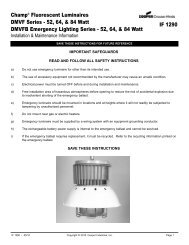
In order to properly select an overcurrent device for a motor starter, four areas<br />
require particular attention:<br />
1. Withstand rating of the contactor.<br />
2. Wire Damage,<br />
3. Cross-over point of the fuse and relay curve,<br />
4. <strong>Motor</strong> Damage.<br />
Please refer to the following graph.<br />
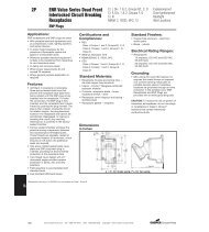
Contactor Withstand Rating<br />
The first area of concern is the withstand rating of the contactor. In order to<br />
prevent damage to the contactor, the maximum peak let-through current (I p )<br />
and maximum clearing energy (I 2 t) (amps 2 seconds) of the fuse must be less<br />
than the equivalent ratings for the contactor. The clearing time and let-through<br />
characteristics of the fuse must be considered when verifying adequate<br />
protection of the contactor.<br />
Wire Damage<br />
Secondly, motor circuit conductors have a withstand rating that must not be<br />
exceeded. If the overcurrent protective device is not capable of limiting the<br />
short-circuit current to a value below the wire with-stand, the wire may be<br />
damaged, or destroyed.<br />
©2005 <strong>Cooper</strong> Bussmann<br />
1,000<br />
TIME IN SECONDS<br />
100<br />
10<br />
1<br />
.1<br />
.01<br />
10<br />
100<br />
1,000<br />
CURRENT IN AMPERES<br />
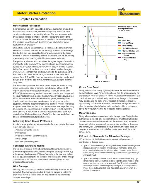
Cross Over Point<br />
Thirdly, the cross-over point (I c ) is the point where the fuse curve intersects<br />
the overload relay curve. For current levels less than the cross-over point the<br />
overload relay opens the circuit. For current values greater than the cross-over<br />
point the fuses open the circuit and prevent thermal damage to the overload<br />
relay, contacts, and the motor circuit. This point of intersection should be<br />
approximately 7-10 times Ie, where Ie is rated current. Ideally the fuse should<br />
allow the overload relay to function under overload conditions, and operate<br />
before the overcurrent reaches the contactor’s breaking capacity.<br />
<strong>Motor</strong> Damage<br />
Finally, all motors have an associated motor damage curve. Single phasing,<br />
overworking, and locked rotor conditions are just a few of the situations that<br />
cause excessive currents in motor circuits. Excessive currents cause motors<br />
to overheat, which in turn causes the motor winding insulation to deteriorate<br />
and ultimately fail. Overload relays and dual-element, time-delay fuses, are<br />
designed to open the motor circuit before current levels reach the motor<br />
damage curve.<br />
IEC and UL Standards for Allowable Damage<br />
IEC 947-4-1 and UL508E differentiate between two different types of<br />
coordination, or damage levels.<br />
— Type “1” Considerable damage, requiring replacement. No external damage to the<br />
enclosure. short circuit protective devices interrupt intermediate to high shortcircuit<br />
currents which exceed the withstand rating of the motor starter. A noncurrent-<br />
limiting device will interrupt these high currents, but this type of damage<br />
will typically result.<br />
— Type “2” “No Damage” is allowed to either the contactor or overload relay. Light<br />
contact welding is allowed, but must be easily separable. (Note: If access is not<br />
possible and the contacts cannot be separated, Type “2” protection cannot be<br />
achieved.) This level of protection typically can only be provided by a currentlimiting<br />
device, that is, one which limits the available short-circuit current to a<br />
significantly lower value.<br />
10,000<br />
<strong>Motor</strong> and <strong>Motor</strong> Circuit<br />
Damage <strong>Protection</strong><br />
10 H.P @ 460V<br />
Legend:<br />
<strong>Motor</strong> Start<br />
Overload Relay<br />
<strong>Motor</strong> Damage<br />
12 AWG Wire Damage<br />
Thermal Withstand Limit<br />
Contactor Breaking<br />
Current<br />
Contactor Withstand<br />
30I 2 e<br />
161
<strong>Motor</strong> <strong>Starter</strong> <strong>Protection</strong><br />
Graphic Explanation<br />
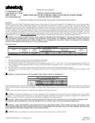
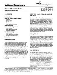
Five Choices — 1 Solution<br />
IEC <strong>Motor</strong> <strong>Starter</strong> <strong>Protection</strong><br />
Five methods of providing motor starter overcurrent protection are delineated<br />
in the five examples that follow. In noting the levels of protection provided by<br />
each method, it becomes apparent that the use of dual-element, time-delay<br />
fuses (Example 5) is the only one that gives protection at all levels whether it<br />
be “Type 2,” “Back-up Overload,” “Back-up Single-Phase,” etc.<br />
These examples are based on a typical motor circuit consisting of an IEC<br />
<strong>Starter</strong>, and a 10 HP, 460V motor (Service factor = 1.15). These “Level of<br />
<strong>Protection</strong>” examples reflect the branch circuit protective device operating in<br />
combination with the IEC starter overload relays sized at approximately 115%<br />
of motor FLA and contactor Ie = 18 amps.<br />
Example 1<br />
Example 2<br />
1,000<br />
TIME IN SECONDS<br />
100<br />
10<br />
1<br />
.1<br />
.01<br />
1,000<br />
TIME IN SECONDS<br />
100<br />
10<br />
10<br />
1<br />
.1<br />
.01<br />
10<br />
100<br />
Crossover<br />
Point<br />
I c = 5.5 ≈ I e<br />
1,000<br />
CURRENT IN AMPERES<br />
100<br />
1,000<br />
CURRENT IN AMPERES<br />
10,000<br />
10,000<br />
<strong>Motor</strong> Circuit Protector<br />
(700% FLA)<br />
Legend:<br />
<strong>Motor</strong> Start<br />
Overload Relay<br />
<strong>Motor</strong> Damage<br />
12 AWG Wire Damage<br />
Thermal Withstand Limit<br />
Contactor Breaking<br />
Current<br />
Contactor Withstand<br />
30I e<br />
2<br />
MCP (700%)<br />
Level of <strong>Protection</strong>:<br />
Type "2"<br />
Single-Phase<br />
Back-up Single-Phase<br />
Overload<br />
Back-up Overload<br />
Meets 110.10<br />
Meets 430.52<br />
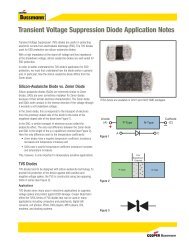
Molded Case Circuit<br />
Breaker<br />
(250% FLA)<br />
Legend:<br />
<strong>Motor</strong> Start<br />
Overload Relay<br />
<strong>Motor</strong> Damage<br />
12 AWG Wire Damage<br />
No<br />
Yes<br />
No<br />
Yes<br />
No<br />
No<br />
Yes<br />
Thermal Withstand Limit<br />
Contactor Breaking<br />
Current<br />
Contactor Withstand<br />
30I e<br />
2<br />
MCCB 40A<br />
Level of <strong>Protection</strong>:<br />
Type "2"<br />
Single-Phase<br />
Back-up Single-Phase<br />
Overload<br />
Back-up Overload<br />
Meets 110.10<br />
Meets 430.52<br />
No<br />
Yes<br />
No<br />
Yes<br />
No<br />
No<br />
Yes<br />
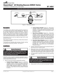
Example 3<br />
Example 4<br />
Example 5<br />
1,000<br />
100<br />
TIME IN SECONDS<br />
10<br />
1<br />
.1<br />
.01<br />
1,000<br />
100<br />
TIME IN SECONDS<br />
10<br />
1<br />
.1<br />
.01<br />
1,000<br />
100<br />
TIME IN SECONDS<br />
10<br />
1<br />
.1<br />
.01<br />
10<br />
10<br />
10<br />
100<br />
Crossover<br />
Point<br />
I c = 10 ≈ I e<br />
1,000<br />
CURRENT IN AMPERES<br />
100<br />
Crossover<br />
Point<br />
I c = 10 X I e<br />
1,000<br />
CURRENT IN AMPERES<br />
100<br />
1,000<br />
CURRENT IN AMPERES<br />
10,000<br />
10,000<br />
10,000<br />
Fast-Acting Fuse<br />
(300% FLA)<br />
Legend:<br />
<strong>Motor</strong> Start<br />
Overload Relay<br />
<strong>Motor</strong> Damage<br />
12 AWG Wire Damage<br />
Thermal Withstand Limit<br />
Contactor Breaking<br />
Current<br />
Contactor Withstand<br />
30I e<br />
2<br />
Fast-Acting Fuse 45A<br />
Level of <strong>Protection</strong>:<br />
Type "2"<br />
Single-Phase<br />
Back-up Single-Phase<br />
Overload<br />
Back-up Overload<br />
Meets 110.10<br />
Meets 430.52<br />
Yes<br />
Yes<br />
No<br />
Yes<br />
No<br />
Yes<br />
Yes<br />
Dual-Element, Time-Delay<br />
Fuse<br />
(175% FLA)<br />
Legend:<br />
<strong>Motor</strong> Start<br />
Overload Relay<br />
<strong>Motor</strong> Damage<br />
12 AWG Wire Damage<br />
Thermal Withstand Limit<br />
Contactor Breaking<br />
Current<br />
Contactor Withstand<br />
30I e<br />
2<br />
Low-Peak, Dual-Element,<br />
Time-Delay 25A<br />
Level of <strong>Protection</strong>:<br />
Type "2"<br />
Single-Phase<br />
Back-up Single-Phase<br />
Overload<br />
Back-up Overload<br />
Meets 110.10<br />
Meets 430.52<br />
Dual-Element, Time-Delay<br />
Fuse<br />
(125% ) - Class RK1 or J<br />
Legend:<br />
Yes<br />
Yes<br />
No<br />
Yes<br />
No<br />
Yes<br />
Yes<br />
I c = 8 I e Thermal Withstand Limit<br />
<strong>Motor</strong> Start<br />
Overload Relay<br />
Crossover<br />
Point<br />
<strong>Motor</strong> Damage<br />
12 AWG Wire Damage<br />
X<br />
Contactor Breaking<br />
Current<br />
Contactor Withstand<br />
30I e<br />
2<br />
Low-Peak, Dual-Element,<br />
Time-Delay 17<br />
1 2 A<br />
Level of <strong>Protection</strong>:<br />
Type "2"<br />
Single-Phase<br />
Back-up Single-Phase<br />
Overload<br />
Back-up Overload<br />
Meets 110.10<br />
Meets 430.52<br />
Yes<br />
Yes<br />
Yes<br />
Yes<br />
Yes<br />
Yes<br />
Yes<br />
162 ©2005 <strong>Cooper</strong> Bussmann
<strong>Motor</strong> <strong>Starter</strong> <strong>Protection</strong><br />
Low Voltage <strong>Motor</strong> Controllers<br />
<strong>Motor</strong> Controller Marking<br />
A new 2005 NEC® 430.8 requirement is that most motor controllers be<br />
marked with their short-circuit current rating (SCCR). Controller manufacturers<br />
have the discretion to test, list, and mark their controllers at the standard fault<br />
levels of UL 508 (shown in the table below) or the manufacturer can choose to<br />
test, list and mark for higher levels of short-circuit currents. A controller with a<br />
marked SCCR makes it easier to establish the short-circuit current rating for<br />
an industrial control panel as is now required in NEC ® 409.110.<br />
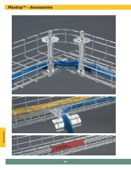
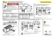
<strong>Motor</strong> Controller <strong>Protection</strong><br />
The diagram below shows a Size 2, combination motor controller supplying a<br />
460 volt, 3Ø, 20Hp motor. The short-circuit withstand of this and other motor<br />
controllers are established so that they may be properly protected from short<br />
circuit damage.<br />
Short Circuit <strong>Protection</strong> of <strong>Motor</strong> Controller<br />
A paragraph in NEC ® 430.52 states:<br />
Where maximum branch circuit short circuit and ground fault protective<br />
device ratings are shown in the manufacturer’s overload relay table for use<br />
with a motor controller or are otherwise marked on the equipment, they<br />
shall not be exceeded even if higher values are allowed as shown above.**<br />
** “Above” refers to other portions of 430-52 not shown here.<br />
This paragraph means that the branch circuit overcurrent protection for<br />
overload relays in motor controllers must be no greater than the maximum<br />
size as shown in the manufacturer’s overload relay table. These maximum<br />
branch circuit sizes must be observed even though other portions of 430.52<br />
allow larger sizing of branch circuit overcurrent protection.<br />
The reason for this maximum overcurrent device size is to provide short circuit<br />
protection for the overload relays and motor controller.<br />
40,000 RMS<br />
Symmetrical<br />
Available<br />
3Ø, 460V<br />
Low-Peak<br />
Dual-Element,<br />
Time-Delay Fuse<br />
M<br />
Typical Size 2 Controller<br />
20HP<br />
3Ø, 460V<br />
27 F.L.A.<br />
There are several independent organizations engaged in regular testing of<br />
motor controllers under short circuit conditions. One of these, Underwriter’s<br />
Laboratories, tests controllers rated one horsepower or less and 300V or less<br />
with 1000 amps short-circuit current available to the controller test circuit.<br />
Controllers rated 50Hp or less are tested with 5000 amps available and<br />
controllers rated above 50Hp to 200Hp are tested with 10,000 amps available.<br />
See the table below for these values.*<br />
<strong>Motor</strong> Controller<br />
Test Short Circuit<br />
HP Rating<br />
Current Available*<br />
1Hp or less and 300V or less<br />
1000A<br />
50Hp or less<br />
5000A<br />
Greater than 50Hp to 200Hp 10,000A<br />
201Hp to 400Hp 18,000A<br />
401Hp to 600Hp 30,000A<br />
601Hp to 900Hp 42,000A<br />
901Hp to 1600Hp 85,000A<br />
* From Industrial Control Equipment, UL508.<br />
It should be noted that these are basic short circuit requirements. Higher,<br />
combination ratings are attainable if tested to an applicable standard.<br />
However, damage is usually allowed.<br />
430.52 of the National Electrical Code ® allows dual-element, time-delay fuses<br />
and other overcurrent protective devices to be sized for branch circuit<br />
protection (short circuit protection only). Controller manufacturers often affix<br />
labels to the inside of the motor starter cover which recommend the maximum<br />
size fuse for each overload relay size.<br />
©2005 <strong>Cooper</strong> Bussmann<br />
163
<strong>Motor</strong> <strong>Starter</strong> <strong>Protection</strong><br />
Type 1 Versus Type 2 <strong>Protection</strong><br />
UL has developed a short circuit test procedure designed to verify that motor<br />
controllers will not be a safety hazard and will not cause a fire.<br />
Compliance to the standard allows deformation of the enclosure, but the door<br />
must not be blown open and it must be possible to open the door after the<br />
test. In the standard short circuit tests, the contacts must not disintegrate, but<br />
welding of the contacts is considered acceptable. Tests allow the overload<br />
relay to be dam-aged with burnout of the current element completely acceptable.<br />
For short circuit ratings in excess of the standard levels listed in UL508,<br />
the damage allowed is even more severe. Welding or complete disintegration<br />
of contacts is acceptable and complete burnout of the overload relay is<br />
allowed. Therefore, a user cannot be certain that the motor starter will not be<br />
damaged just because it has been UL Listed for use with a specific branch<br />
circuit protective device. UL tests are for safety, with the doors closed but do<br />
allow a significant amount of damage as long as it is contained within the<br />
enclosure.<br />
Photo 1 Before Test: MCP as motor<br />
branch circuit protection for 10HP, IEC<br />
<strong>Starter</strong> with 22,000 amps available<br />
at 480V.<br />
Photo 2: Same as Photo 1, but during<br />
the test with MCP as the motor branch<br />
circuit protection. The heater elements<br />
vaporized and the contacts were<br />
severely welded. Extensive starter<br />
repair or total starter replacement<br />
would be required. This level of<br />
damage is permissible by UL508 or<br />
UL508E/IEC60947-4-1 Type 1<br />
protection.<br />
Photo 3 During Test: same test circuit<br />
and same type starter during short<br />
circuit interruption. The difference is<br />
current-limiting fuses provide the motor<br />
branch circuit protection. This<br />
illustrates the level of protection<br />
required by UL508E and IEC 60947-4-<br />
1 for Type 2 “no damage” protection.<br />
The heaters and overload relays<br />
maintained calibration, which is<br />
extremely important to retain circuit<br />
overload protection. This starter could<br />
be put back into service without any<br />
repair.<br />
In order to properly select a branch circuit protective device that not only<br />
provides motor branch circuit protection, but also protects the circuit components<br />
from damage, the designer must look beyond mere safety standards.<br />
Coordination (protection) of the branch circuit protective device and the motor<br />
starter is necessary to insure that there will be no damage or danger to either<br />
the starter or the surrounding equipment. There is an “Outline of Investigation,”<br />
(UL508E) and an IEC (International Electrotechnical Commission) Standard<br />
IEC Publication 60947, “Low Voltage Switchgear and Control, Part 4-1:<br />
Contactors and <strong>Motor</strong> <strong>Starter</strong>s,” that offer guidance in evaluating the level of<br />
damage likely to occur during a short circuit with various branch circuit<br />
protective devices. These standards address the coordination (protection)<br />
between the branch circuit protective device and the motor starter. They<br />
provide a method to measure the performance of these devices should a short<br />
circuit occur. They define two levels of protection (coordination) for the motor<br />
starter:<br />
Type 1.<br />
Type 2.<br />
Considerable damage to the contactor and overload relay<br />
is acceptable. Replacement of components or a<br />
completely new starter may be needed. There must be no<br />
discharge of parts beyond the enclosure.<br />
No damage is allowed to either the contactor or over-load<br />
relay. Light contact welding is allowed, but must be easily<br />
separable.<br />
Where Type 2 protection is desired, the controller manufacturer must verify<br />
that Type 2 protection can be achieved by using a specified protective device.<br />
US manufacturers have both their NEMA and IEC motor controllers verified to<br />
meet the Type 2 requirements outlined in UL508E and IEC 60947-4. As of this<br />
writing only current-limiting devices have been able to provide the current<br />
limitation necessary to provide verified Type 2 protection. In many cases,<br />
Class J, Class RK1, or Class CC fuses are required, because Class RK5<br />
fuses and circuit breakers aren’t fast enough under short circuit conditions to<br />
provide Type 2 protection.<br />
Tables: Type 2 <strong>Motor</strong> <strong>Starter</strong>/<strong>Cooper</strong> Bussmann Fuses<br />
On the following pages are motor starters of several manufacturers that have<br />
been verified by testing for Type 2 protection using the fuses denoted. These<br />
are maximum fuse sizes; for specific applications, it may be desirable to size<br />
closer. In some cases, the fuse type/amp rating shown is greater than that<br />
permitted for branch circuit protection for a single motor per 430.52<br />
(footnoted); however, the size may be applicable for group motor protection<br />
applications. In a few cases, the fuse type/amp rating may be too small for<br />
typical motor starting applications (footnoted). It is recommended to use these<br />
fuse types/amp ratings in conjunction with the fuse type/sizing philosophy<br />
(backup motor overload, optimal or maximum branch circuit protection - see<br />
<strong>Motor</strong> <strong>Protection</strong> Table explanation in <strong>Motor</strong> Circuit <strong>Protection</strong> Section of this<br />
book.) This data was obtained from the manufacturers or their web sites.<br />
The following pages have Fuse/<strong>Starter</strong> (IEC & NEMA) Type 2 “no damage”<br />
Tables for:<br />
General Electric 165 to 169<br />
Rockwell Automation/Allen-Bradley 170 to 171<br />
Square D Co. 172 to 175<br />
Siemens 176 to 177<br />
Cutler-Hammer 178 to 180<br />
164 ©2005 <strong>Cooper</strong> Bussmann
<strong>Motor</strong> Controller & Fuse Selection For Type 2 <strong>Protection</strong><br />
General Electric Company — IEC (UL & CSA Verified)<br />
200 Volt, Three-Phase <strong>Motor</strong>s<br />
MAX FUSE<br />
HP (FLC) CONTACTOR OLR LPJ_SP<br />
CLASS J<br />
0.5 (2.5) CL00, CL01, CL02, CL03, CL04, CL25, CL45 RT*1J 4<br />
0.5 (2.5) CL00, CL01, CL02, CL03, CL04, CL25, CL45 RT*1K 8†<br />
0.75 (3.7) CL00, CL01, CL02, CL03, CL04, CL25, CL45 RT*1K 8<br />
1 (4.8) CL00, CL01, CL02, CL03, CL04, CL25, CL45 RT*1L 10<br />
1.5 (6.9) CL00, CL01, CL02, CL03, CL04, CL25, CL45 RT*1M 12<br />
2 (7.8) CL00, CL01, CL02, CL03, CL04, CL25, CL45 RT*1N 20†<br />
3 (11.0) CL00, CL01, CL02, CL03, CL04, CL25, CL45 RT*1P 20<br />
5 (17.5) CL02, CL03, CL04, CL25, CL45 RT*1S 35<br />
5 (17.5) CL06, CL07, CL08, CL09, CL10 RT*2B 35<br />
5 (17.5) CL03, CL04, CL45 RT*1T 45†<br />
7.5 (25.3) CL04, CL05 RT*1U 45<br />
7.5 (25.3) CL06, CL07, CL08, CL09, CL10 RT*2D 60†<br />
7.5 (25.3) CL04, CL45 RT*1V 60†<br />
10 (32.2) CL45 RT*1W 70<br />
10 (32.2) CL06, CL07, CL08, CL09, CL10 RT*2E 70<br />
15 (48.3) CL07, CL08, CL09, CL10 RT*2G 100<br />
20 (62.1) CL08, CL09, CL10 RT*2H 125<br />
20 (62.1) CK08, CK09, CK95 RT*3B 125<br />
25 (78.2) CK08, CK09 RT*3C 150<br />
230 Volt, Three-Phase <strong>Motor</strong>s<br />
MAX FUSE<br />
HP (FLC) CONTACTOR OLR LPJ_SP<br />
CLASS J<br />
0.5 (2.2) CL00, CL01, CL02, CL03, CL04, CL25, CL45 RT*1J 4<br />
0.75 (3.2) CL00, CL01, CL02, CL03, CL04, CL25, CL45 RT*1K 8†<br />
1 (4.2) CL00, CL01, CL02, CL03, CL04, CL25, CL45 RT*1L 10<br />
1.5 (6.0) CL00, CL01, CL02, CL03, CL04, CL25, CL45 RT*1L 10<br />
2 (6.8) CL00, CL01, CL02, CL03, CL04, CL25, CL45 RT*1M 12<br />
3 (9.6) CL00, CL01, CL02, CL03, CL04, CL25, CL45 RT*1N 20<br />
5 (15.2) CL02, CL03, CL04, CL25, CL45 RT*1S 35†<br />
5 (15.2) CL06, CL07, CL08, CL09, CL10 RT*2B 35†<br />
7.5 (22.0) CL03, CL04, CL45 RT*1T 45<br />
7.5 (22.0) CL06, CL07, CL08, CL09, CL10 RT*2C 45<br />
7.5 (22.0) CL03, CL04, CL45 RT*1U 45<br />
10 (28.0) CL04 RT*1V 60<br />
10 (28.0) CL45 RT*1V 60<br />
10 (28.0) CL06, CL07, CL08, CL09, CL10 RT*2D 60<br />
15 (42.0) CL06, CL07, CL08, CL09, CL10 RT*2F 90<br />
20 (54.0) CL07, CL08, CL09, CL10 RT*2G 100<br />
20 (54.0) CL07, CL08, CL09, CL10 RT*2H 125†<br />
25 (68.0) CK08, CK09, CK95 RT*3B 125<br />
25 (68.0) CL08, CL09, CL10 RT*2J 125<br />
30 (80.0) CK08, CK09, CK95 RT*3B 125<br />
25 (68.0) CK08, CK09 RT*3C 150<br />
* Replace * with “A” or “M”<br />
† Sized larger than code max for single motor.<br />
©2005 <strong>Cooper</strong> Bussmann<br />
165
<strong>Motor</strong> Controller & Fuse Selection For Type 2 <strong>Protection</strong><br />
General Electric Company — IEC (UL & CSA Verified)<br />
460 Volt, Three-Phase <strong>Motor</strong>s<br />
MAX FUSE<br />
HP (FLC) CONTACTOR OLR LPJ_SP<br />
CLASS J<br />
0.5 (1.1) CL00, CL01, CL02, CL03, CL04, CL25, CL45 RT*1F 1.5††<br />
0.5 (1.1) CL00, CL01, CL02, CL03, CL04, CL25, CL45 RT*1G 2<br />
0.75 (1.6) CL00, CL01, CL02, CL03, CL04, CL25, CL45 RT*1H 4†<br />
1 (2.1) CL00, CL01, CL02, CL03, CL04, CL25, CL45 RT*1J 4<br />
1.5 (3.0) CL00, CL01, CL02, CL03, CL04, CL25, CL45 RT*1K 8†<br />
2 (3.4) CL00, CL01, CL02, CL03, CL04, CL25, CL45 RT*1K 8†<br />
3 (4.8) CL00, CL01, CL02, CL03, CL04, CL25, CL45 RT*1L 10<br />
5 (7.6) CL00, CL01, CL02, CL03, CL04, CL25, CL45 RT*1N 20†<br />
7.5 (11.0) CL00, CL01, CL02, CL03, CL04, CL25, CL45 RT*1P 20<br />
10 (14.0) CL02, CL03, CL04, CL25, CL45 RT*1R 25<br />
10 (14.0) CL06, CL07, CL08, CL09, CL10 RT*2A 30<br />
15 (21.0) CL03, CL04, CL45 RT*1T 45<br />
15 (21.0) CL06, CL07, CL08, CL09, CL10 RT*2C 45<br />
20 (27.0) CL04, CL45 RT*1V 60<br />
20 (27.0) CL06, CL07, CL08, CL09, CL10 RT*2D 60<br />
25 (34.0) CL45 RT*1W 70<br />
25 (34.0) CL06, CL07, CL08, CL09, CL10 RT*2E 70<br />
30 (40.0) CL06, CL07, CL08, CL09, CL10 RT*2E 70<br />
30 (40.0) CL06, CL07, CL08, CL09, CL10 RT*2F 90<br />
40 (52.0) CL07, CL08, CL09, CL10 RT*2G 100<br />
50 (65.0) CL08, CL09, CL10 RT*2H 125<br />
50 (65.0) CL08, CL09, CL10 RT*3B 125<br />
50 (65.0) CL08, CL09, CL10 RT*2J 125<br />
60 (77.0) CL09, CL10 RT*3B 125<br />
60 (77.0) CL09, CL10 RT*2K 150<br />
575 Volt, Three-Phase <strong>Motor</strong>s<br />
MAX FUSE<br />
HP (FLC) CONTACTOR OLR LPJ_SP<br />
CLASS J<br />
0.5 (0.9) CL00, CL01, CL02, CL03, CL04, CL25, CL45 RT*1F 1.5<br />
0.75 (1.3) CL00, CL01, CL02, CL03, CL04, CL25, CL45 RT*1G 2<br />
0.75 (1.3) CL00, CL01, CL02, CL03, CL04, CL25, CL45 RT*1H 4†<br />
1 (1.7) CL00, CL01, CL02, CL03, CL04, CL25, CL45 RT*1H 4†<br />
1.5 (2.4) CL00, CL01, CL02, CL03, CL04, CL25, CL45 RT*1J 4<br />
2 (2.7) CL00, CL01, CL02, CL03, CL04, CL25, CL45 RT*1J 4<br />
2 (2.7) CL00, CL01, CL02, CL03, CL04, CL25, CL45 RT*1K 8†<br />
3 (3.9) CL00, CL01, CL02, CL03, CL04, CL25, CL45 RT*1K 8<br />
5 (6.1) CL00, CL01, CL02, CL03, CL04, CL25, CL45 RT*1L 10<br />
5 (6.1) CL00, CL01, CL02, CL03, CL04, CL25, CL45 RT*1M 12<br />
7.5 (9.0) CL00, CL01, CL02, CL03, CL04, CL25, CL45 RT*1N 20<br />
10 (11.0) CL00, CL01, CL02, CL03, CL04, CL25, CL45 RT*1P 20<br />
15 (17.0) CL02, CL03, CL04, CL25, CL45 RT*1S 35<br />
15 (17.0) CL06, CL07, CL08, CL09, CL10 RT*2B 35<br />
20 (22.0) CL03, CL04, CL45 RT*1T 45<br />
20 (22.0) CL06, CL07, CL08, CL09, CL10 RT*2C 45<br />
20 (22.0) CL03, CL04, CL45 RT*1U 45<br />
25 (27.0) CL04, CL45 RT*1V 60<br />
25 (27.0) CL06, CL07, CL08, CL09, CL10 RT*2D 60<br />
30 (32.0) CL04, CL45 RT*1V 60<br />
30 (32.0) CL06, CL07, CL08, CL09, CL10 RT*2D 60<br />
30 (32.0) CL45 RT*1W 70<br />
30 (32.0) CL06, CL07, CL08, CL09, CL10 RT*2E 70<br />
40 (41.0) CL06, CL07, CL08, CL09, CL10 RT*2E 70<br />
40 (41.0) CL06, CL07, CL08, CL09, CL10 RT*2F 90<br />
50 (52.0) CL07, CL08, CL09, CL10 RT*2G 100<br />
60 (62.0) CL07, CL08, CL09, CL10 RT*2H 125<br />
60 (62.0) CK08, CK09, CK95 RT*3B 125<br />
75 (77.0) CK08, CK09, CK95 RT*3B 125<br />
75 (77.0) CK08, CK09 RT*3C 150<br />
* Replace * with “A” or “M”<br />
†† May be too small to allow some motors to start.<br />
† Sized larger than code max for single motor.<br />
166 ©2005 <strong>Cooper</strong> Bussmann
<strong>Motor</strong> Controller & Fuse Selection For Type 2 <strong>Protection</strong><br />
General Electric Company — NEMA (UL & CSA Verified)<br />
200 Volt, Three-Phase <strong>Motor</strong>s<br />
MAX FUSE<br />
LPJ_SP<br />
HP (FLC) OLR CLASS J<br />
0.5 (2.5) CR324CXE 6<br />
0.5 (2.5) CR123C326A 6<br />
0.75 (3.7) CR123C356A 8<br />
0.75 (3.7) CR324CXF 10<br />
1 (4.8) CR324CXF 10<br />
1 (4.8) CR123C526A 10<br />
1.5 (6.9) CR324CXG 15<br />
1.5 (6.9) CR123C778A 15<br />
1.5 (6.9) CR123C695A 15<br />
2 (7.8) CR324CXG 17.5<br />
2 (7.8) CR123C867A 17.5<br />
3 (11.0) CR324CXG 20<br />
3 (11.0) CR123C125B 20<br />
5 (17.5) CR234CXH 35<br />
5 (17.5) CR234FXK 35<br />
5 (17.5) CR123C180B 35<br />
5 (17.5) CR123C198B 35<br />
5 (17.5) CR123F233B 35<br />
230 Volt, Three-Phase <strong>Motor</strong>s<br />
MAX FUSE<br />
LPJ_SP<br />
HP (FLC) OLR CLASS J<br />
0.5 (2.2) CR123C268A 5<br />
0.5 (2.2) CR324CXE 6<br />
0.75 (3.2) CR324CXF 7<br />
0.75 (3.2) CR123C356A 7<br />
1 (4.2) CR324CXF 10<br />
1 (4.2) CR123C466A 10<br />
1.5 (6.0) CR324CXF 15<br />
1.5 (6.0) CR123C695A 15<br />
2 (6.8) CR324CXG 15<br />
2 (6.8) CR324DXG 15<br />
2 (6.8) CR123C778A 15<br />
3 (9.6) CR324CXG 20<br />
3 (9.6) CR324DXG 20<br />
3 (9.6) CR123C104B 20<br />
5 (15.2) CR234CXH 30<br />
5 (15.2) CR234DXH 30<br />
5 (15.2) CR123C163B 30<br />
7.5 (22.0) CR324DXH 45<br />
7.5 (22.0) CR324FXK 45<br />
7.5 (22.0) CR123C228B 45<br />
7.5 (22.0) CR123C250B 45<br />
7.5 (22.0) CR123C270B 45<br />
460 Volt, Three-Phase <strong>Motor</strong>s<br />
MAX FUSE<br />
LPJ_SP<br />
HP (FLC) OLR CLASS J<br />
0.5 (1.1) CR123C131A 2.5<br />
0.5 (1.1) CR324CXD 3<br />
0.75 (1.6) CR324CXD 3.5<br />
0.75 (1.6) CR123C196A 3.5<br />
1 (2.1) CR123C268A 5<br />
1 (2.1) CR324CXE 6<br />
1.5 (3.0) CR324CXE 6<br />
1.5 (3.0) CR123C356A 6<br />
2 (3.4) CR324CXF 7<br />
2 (3.4) CR123C379A 7<br />
3 (4.8) CR324CXF 10<br />
3 (4.8) CR123C526A 10<br />
5 (7.6) CR324CXG 15<br />
5 (7.6) CR324DXG 15<br />
5 (7.6) CR123C867A 15<br />
7.5 (11.0) CR324CXG 20<br />
7.5 (11.0) CR324DXG 20<br />
7.5 (11.0) CR123C125B 20<br />
10 (14.0) CR234CXH 30<br />
10 (14.0) CR234DXH 30<br />
10 (14.0) CR123C163B 30<br />
15 (21.0) CR324CXH 45<br />
15 (21.0) CR324DXH 45<br />
15 (21.0) CR324FXK 45<br />
15 (21.0) CR123C228B 45<br />
15 (21.0) CR123F243B 45<br />
575 Volt, Three-Phase <strong>Motor</strong>s<br />
MAX FUSE<br />
LPJ_SP<br />
HP (FLC) OLR CLASS J<br />
0.5 (0.9) CR123C109A 2<br />
0.5 (0.9) CR324CXD 3<br />
0.75 (1.3) CR324CXD 3<br />
0.75 (1.3) CR123C163A 3<br />
1 (1.7) CR324CXD 3.5<br />
1 (1.7) CR123C196A 3.5<br />
1 (1.7) CR324CXE 3.5<br />
1.5 (2.4) CR324CXE 6<br />
1.5 (2.4) CR123C301A 6<br />
2 (2.7) CR324CXE 6<br />
2 (2.7) CR123C326A 6<br />
3 (3.9) CR324CXF 10<br />
3 (3.9) CR123C419A 10<br />
5 (6.1) CR324CXF 15<br />
5 (6.1) CR123C695A 15<br />
7.5 (9.0) CR324CXG 20<br />
7.5 (9.0) CR324DXG 20<br />
7.5 (9.0) CR123C104B 20<br />
7.5 (9.0) CR123C955A 20<br />
10 (11.0) CR123C125B 20<br />
10 (11.0) CR324CXG 20<br />
10 (11.0) CR324DXG 20<br />
15 (17.0) CR234DXH 35<br />
15 (17.0) CR234FXK 35<br />
15 (17.0) CR123C180B 35<br />
20 (22.0) CR324DXH 45<br />
20 (22.0) CR324FXK 45<br />
20 (22.0) CR123C228B 45<br />
20 (22.0) CR123C250B 45<br />
20 (22.0) CR123C270B 45<br />
©2005 <strong>Cooper</strong> Bussmann<br />
167
<strong>Motor</strong> Controller & Fuse Selection For Type 2 <strong>Protection</strong><br />
General Electric Company — NEMA (UL & CSA Verified)<br />
200 Volt, Three-Phase <strong>Motor</strong>s<br />
MAX FUSE<br />
LPJ_SP KRP-C_SP<br />
HP (FLC) OLR CLASS J CLASS L<br />
7.5 (25.3) CR324DXH 50<br />
7.5 (25.3) CR324FXK 50<br />
7.5 (25.3) CR123C273B 50<br />
7.5 (25.3) CR123C303B 50<br />
7.5 (25.3) CR123F300B 50<br />
10 (32.2) CR324DXJ 70<br />
10 (32.2) CR324FXK 70<br />
10 (32.2) CR123C330B 70<br />
10 (32.2) CR123F395B 70<br />
15 (48.3) CR324DXJ 100<br />
15 (48.3) CR324FXL 100<br />
15 (48.3) CR123F614B 100<br />
20 (62.1) CR324FXL 125<br />
20 (62.1) CR123F772B 125<br />
25 (78.2) CR234FXM 175<br />
25 (78.2) CR324GXP 175<br />
25 (78.2) CR123F104C 175<br />
30 (92.0) CR234FXM 200<br />
30 (92.0) CR324GXP 200<br />
30 (92.0) CR123F118C 200<br />
40 (120.0) CR234FXM 250<br />
40 (120.0) CR324GXP 250<br />
40 (120.0) CR123F161C 250<br />
50 (150.0) CR324GXQ 300<br />
50 (150.0) CR324HXS 300<br />
60 (177.0) CR324GXQ 350<br />
60 (177.0) CR324HXS 350<br />
75 (221.0) CR324GXQ 450<br />
75 (221.0) CR324HXS 450<br />
100 (285.0) CR324HXT 600<br />
125 (359.0) CR324HXT 1000<br />
150 (414.0) CR324HXT 1000<br />
230 Volt, Three-Phase <strong>Motor</strong>s<br />
MAX FUSE<br />
LPJ_SP KRP-C_SP<br />
HP (FLC) OLR CLASS J CLASS L<br />
10 (28.0) CR324DXJ 60<br />
10 (28.0) CR324FXK 60<br />
10 (28.0) CR123C303B 60<br />
10 (28.0) CR123F327B 60<br />
15 (42.0) CR324DXJ 90<br />
15 (42.0) CR324FXL 90<br />
15 (42.0) CR123F567B 90<br />
15 (42.0) CR123F487B 90<br />
15 (42.0) CR123F440B 90<br />
20 (54.0) CR324FXL 110<br />
20 (54.0) CR123F719B 110<br />
25 (68.2) CR324FXL 150<br />
25 (68.2) CR324FXM 150<br />
25 (68.2) CR324GXP 150<br />
25 (68.2) CR123F848B 150<br />
25 (68.2) CR123F914B 150<br />
30 (80.0) CR234FXM 175<br />
30 (80.0) CR324GXP 175<br />
30 (80.0) CR123F104C 175<br />
40 (104.0) CR234FXM 225<br />
40 (104.0) CR324GXP 225<br />
40 (104.0) CR123F133C 225<br />
50 (130.0) CR234FXM 250<br />
50 (130.0) CR324GXP 250<br />
50 (130.0) CR123F161C 250<br />
60 (145.0) CR324GXQ 300<br />
60 (145.0) CR324HXS 300<br />
75 (192.0) CR324GXQ 400<br />
75 (192.0) CR324HXS 400<br />
100 (248.0) CR324GXQ 500<br />
100 (248.0) CR324HXS 500<br />
125 (312.0) CR324HXT 900<br />
150 (360.0) CR324HXT 1000<br />
200 (480.0) CR324HXT 1000<br />
168 ©2005 <strong>Cooper</strong> Bussmann
<strong>Motor</strong> Controller & Fuse Selection For Type 2 <strong>Protection</strong><br />
General Electric Company — NEMA (UL & CSA Verified)<br />
460 Volt, Three-Phase <strong>Motor</strong>s<br />
MAX FUSE<br />
LPJ_SP KRP-C_SP<br />
HP (FLC) OLR CLASS J CLASS L<br />
20 (27.0) CR324DXH 60<br />
20 (27.0) CR324DXJ 60<br />
20 (27.0) CR324FXK 60<br />
20 (27.0) CR123C303B 60<br />
20 (27.0) CR123F327B 60<br />
20 (27.0) CR123C330B 60<br />
25 (34.0) CR324DXJ 70<br />
25 (34.0) CR324FXK 70<br />
25 (34.0) CR123C366B 70<br />
25 (34.0) CR123F430B 70<br />
30 (40.0) CR324DXJ 90<br />
30 (40.0) CR324FXL 90<br />
30 (40.0) CR123C400B 90<br />
30 (40.0) CR123F487B (SIZE 3) 90<br />
30 (40.0) CR123F487B (SIZE 4) 90<br />
40 (52.0) CR324FXL 110<br />
40 (52.0) CR123F658B (SIZE 3) 110<br />
40 (52.0) CR123F658B (SIZE 4) 110<br />
50 (65.0) CR324FXL 125<br />
50 (65.0) CR123F772B 125<br />
50 (65.0) CR324FXM 125<br />
50 (65.0) CR324GXP 125<br />
50 (65.0) CR123F848B 125<br />
60 (77.0) CR324FXM 150<br />
60 (77.0) CR324GXP 150<br />
60 (77.0) R123F104C (SIZE 3) 150<br />
60 (77.0) R123F104C (SIZE 4) 150<br />
75 (96.0) CR234FXM 200<br />
75 (96.0) CR324GXP 200<br />
75 (96.0) CR123F118C 200<br />
100 (124.0) CR234FXM 250<br />
100 (124.0) CR324GXP 250<br />
100 (124.0) CR123F161C 250<br />
125 (156.0) CR324GXQ 350<br />
125 (156.0) CR324HXS 350<br />
150 (180.0) CR324GXQ 400<br />
150 (180.0) CR324HXS 400<br />
200 (240.0) CR324GXQ 500<br />
200 (240.0) CR324HXS 500<br />
250 (302.0) CR324HXT 900<br />
300 (361.0) CR324HXT 1000<br />
350 (414.0) CR324HXT 1000<br />
400 (477.0) CR324HXT 1000<br />
450 (515.0) CR324HXT 1000<br />
575 Volt, Three-Phase <strong>Motor</strong>s<br />
MAX FUSE<br />
LPJ_SP KRP-C_SP<br />
HP (FLC) OLR CLASS J CLASS L<br />
25 (27.0) CR324DXH 60<br />
25 (27.0) CR324DXJ 60<br />
25 (27.0) CR324FXK 60<br />
25 (27.0) CR123C303B 60<br />
25 (27.0) CR123F327B 60<br />
25 (27.0) CR123C330B 60<br />
30 (32.0) CR324DXJ 70<br />
30 (32.0) CR324FXK 70<br />
30 (32.0) CR123C330B 70<br />
30 (32.0) CR123F395B 70<br />
40 (41.0) CR324DXJ 90<br />
40 (41.0) CR324FXL 90<br />
40 (41.0) CR123C400B 90<br />
40 (41.0) CR123F567B 90<br />
40 (41.0) CR123F487B 90<br />
50 (52.0) CR324FXL 110<br />
50 (52.0) CR123F658B (SIZE 3) 110<br />
50 (52.0) CR123F658B (SIZE 4) 110<br />
60 (62.0) CR324FXL 125<br />
60 (62.0) CR123F772B 125<br />
75 (77.0) CR324FXM 150<br />
75 (77.0) CR324GXP 150<br />
75 (77.0) R123F104C (SIZE 3) 150<br />
75 (77.0) R123F104C (SIZE 4) 150<br />
100 (99.0) CR234FXM 200<br />
100 (99.0) CR324GXP 200<br />
100 (99.0) CR123F118C 200<br />
125 (125.0) CR234FXM 250<br />
125 (125.0) CR324GXP 250<br />
125 (125.0) CR123F161C 250<br />
150 (144.0) CR324GXQ 300<br />
150 (144.0) CR324HXS 300<br />
200 (192.0) CR324GXQ 400<br />
200 (192.0) CR324HXS 400<br />
250 (242.0) CR324GXQ 500<br />
250 (242.0) CR324HXS 500<br />
300 (289.0) CR324HXT 800<br />
350 (336.0) CR324HXT 1000<br />
400 (382.0) CR324HXT 1000<br />
450 (412.0) CR324HXT 1000<br />
500 (472.0) CR324HXT 1000<br />
©2005 <strong>Cooper</strong> Bussmann<br />
169
<strong>Motor</strong> Controller & Fuse Selection For Type 2 <strong>Protection</strong><br />
Rockwell Automation, Allen-Bradley — IEC (UL & CSA Verified)<br />
200 Volt, Three-Phase <strong>Motor</strong>s<br />
CONTACTOR OVERLOAD RELAY MAX FUSE<br />
BASIC CAT. # BASIC CAT. # LPJ_SP LP-CC<br />
HP (FLC) (a) (b) CLASS J CLASS CC<br />
0.5 (2.5) 100-C09 193-E**EB 6 6<br />
0.75 (3.7) 100-C09 193-E**EB 10 10<br />
1 (4.8) 100-C09 193-E**FB 15† 15<br />
1.5 (6.9) 100-C09 193-E**FB 15 15<br />
2 (7.8) 100-C09 193-E**FB 15 15††<br />
3 (11) 100-C12 193-E**FB 20 20††<br />
5 (17.5) 100-C23 193-E**GB 30 30††<br />
7.5 (25.3) 100-C30 193-E**HC 40<br />
10 (32.2) 100-C37 193-E**HC 50<br />
15 (48.3) 100-C60 193-E**KE 80<br />
20 (62.1) 100-C72 193-E**KE 100<br />
25 (78.2) 100-C85 193-E**KE 100††<br />
230 Volt, Three-Phase <strong>Motor</strong>s<br />
CONTACTOR OVERLOAD RELAY MAX FUSE<br />
BASIC CAT. # BASIC CAT. # LPJ_SP LP-CC<br />
HP (FLC) (a) (b) CLASS J CLASS CC<br />
0.5 (2.2) 100-C09 193-E**DB 6 6<br />
0.75 (3.2) 100-C09 193-E**EB 10† 10<br />
1 (4.2) 100-C09 193-E**FB 15† 15<br />
1.5 (6) 100-C09 193-E**FB 15 15<br />
2 (6.8) 100-C09 193-E**FB 15 15<br />
3 (9.6) 100-C12 193-E**FB 20 20<br />
5 (15.2) 100-C16 193-E**GB 20†† 20††<br />
7.5 (22) 100-C23 193-E**GB 30†† 30††<br />
10 (28) 100-C30 193-E**HC 40††<br />
15 (42) 100-C43 193-E**JD 50††<br />
20 (54) 100-C60 193-E**KE 80††<br />
25 (68) 100-C72 193-E**KE 100<br />
30 (80) 100-C85 193-E**KE 100††<br />
460 Volt, Three-Phase <strong>Motor</strong>s<br />
CONTACTOR OVERLOAD RELAY MAX FUSE<br />
BASIC CAT. # BASIC CAT. # LPJ_SP LP-CC<br />
HP (FLC) (a) (b) CLASS J CLASS CC<br />
0.5 (1.1) 100-C09 193-E**DB 3 3<br />
0.75 (1.6) 100-C09 193-E**DB 6† 6<br />
1 (2.1) 100-C09 193-E**DB 6 6<br />
1.5 (3) 100-C09 193-E**EB 10† 10<br />
2 (3.4) 100-C09 193-E**EB 10† 10<br />
3 (4.8) 100-C09 193-E**FB 15† 15<br />
5 (7.6) 100-C09 193-E**FB 15 15††<br />
7.5 (11) 100-C12 193-E**FB 20 20††<br />
10 (14) 100-C16 193-E**GB 20†† 20††<br />
15 (21) 100-C23 193-E**GB 30†† 30††<br />
20 (27) 100-C30 193-E**HC 40<br />
25 (34) 100-C37 193-E**HC 50<br />
30 (40) 100-C43 193-E**JD 50††<br />
40 (52) 100-C60 193-E**KE 80<br />
50 (65) 100-C72 193-E**KE 100<br />
60 (77) 100-C85 193-E**KE 100††<br />
575 Volt, Three-Phase <strong>Motor</strong>s<br />
CONTACTOR OVERLOAD RELAY MAX FUSE<br />
BASIC CAT. # BASIC CAT. # LPJ_SP LP-CC<br />
HP (FLC) (a) (b) CLASS J CLASS CC<br />
0.5 (0.9) 100-C09 193-E**DB 3 3<br />
0.75 (1.3) 100-C09 193-E**DB 3 3<br />
1 (1.7) 100-C09 193-E**DB 6† 6<br />
1.5 (2.4) 100-C09 193-E**DB 6 6<br />
2 (2.7) 100-C09 193-E**EB 10† 10<br />
3 (3.9) 100-C09 193-E**FB 10 10<br />
5 (6.1) 100-C09 193-E**FB 15 15<br />
5 (7.6) 100-C09 193-E**FB 15 15††<br />
7.5 (9) 100-C09 193-E**FB 15 15††<br />
10 (11) 100-C12 193-E**FB 20 20††<br />
15 (17) 100-C23 193-E**GB 30 30††<br />
20 (22) 100-C30 193-E**HC 40<br />
25 (27) 100-C37 193-E**HC 50<br />
30 (32) 100-C37 193-E**HC 50<br />
40 (41) 100-C60 193-E**KE 80<br />
50 (52) 100-C72 193-E**KE 100<br />
60 (62) 100-C85 193-E**KE 100<br />
(a) Catalog number is not complete, add coil voltage code and auxiliary contact description.<br />
(b) Catalog number is not complete, replace ** with trip class and reset mode.<br />
†† May be too small to allow some motors to start.<br />
† Sized larger than code max for single motor.<br />
170 ©2005 <strong>Cooper</strong> Bussmann
<strong>Motor</strong> Controller & Fuse Selection For Type 2 <strong>Protection</strong><br />
Rockwell Automation, Allen-Bradley — NEMA (UL & CSA Verified)<br />
200 Volt, Three-Phase <strong>Motor</strong>s<br />
MAX FUSE<br />
STARTER† HEATER LPN-RK_SP/LPJ_SP<br />
HP (FLC) SIZE CAT. # # ELEMENT CLASS RK1/J<br />
1.5 (6.9) 0 509-A W48 15<br />
2 (7.8) 0 509-A W50 15<br />
3 (11.0) 0 509-A W53 20<br />
5 (17.5) 1 509-B W59 30<br />
7.5 (25.3) 2 509-C W63 50<br />
10 (32.2) 3 509-D W65 60<br />
15 (48.3) 3 509-D W68 100<br />
20 (62.1) 3 509-D W71 100<br />
25 (78.2) 3 509-D W75 150<br />
30 (92.0) 4 509-E W77 175<br />
40 (120.0) 4 509-E W81 200<br />
50 (150.0) 5 509-F W37 200††<br />
60 (177.1) 5 509-F W39 250††<br />
75 (221.0) 5 509-F W41 350<br />
230 Volt, Three-Phase <strong>Motor</strong>s<br />
MAX FUSE<br />
STARTER† HEATER LPN-RK_SP/LPJ_SP<br />
HP (FLC) SIZE CAT. # ELEMENT CLASS RK1/J<br />
2 (6.8) 0 509-A W48 15<br />
3 (9.6) 0 509-A W52 20<br />
5 (15.2) 1 509-B W57 30<br />
7.5 (22.0) 2 509-C W61 45<br />
10 (28.0) 3 509-C W64 60<br />
15 (42.0) 3 509-D W66 90<br />
20 (54.0) 3 509-D W69 100<br />
25 (68.2) 3 509-D W73 100††<br />
30 (80.0) 3 509-D W75 150<br />
40 (104.0) 4 509-E W79 175<br />
50 (130.0) 4 509-E W83 200<br />
60 (154.0) 5 509-F W37 200††<br />
75 (192.0) 5 509-F W40 300<br />
100 (248.0) 5 509-F W43 400<br />
460 Volt, Three-Phase <strong>Motor</strong>s<br />
MAX FUSE<br />
STARTER† HEATER LPS-RK_SP/LPJ_SP<br />
HP (FLC) SIZE CAT. # ELEMENT CLASS RK1/J<br />
5 (7.6) 0 509-A W49 15<br />
7.5 (11.0) 1 509-B W53 20<br />
10 (14.0) 1 509-B W56 30<br />
15 (21.0) 2 509-C W61 45<br />
20 (27.0) 2 509-C W63 60<br />
25 (34.0) 3 509-D W66 60<br />
30 (40.0) 3 509-D W66 90<br />
40 (52.0) 3 509-D W69 100<br />
50 (65.0) 3 509-D W72 100<br />
60 (77.0) 4 509-E W74 125<br />
75 (96.0) 4 509-E W77 175<br />
100 (124.0) 4 509-E W82 200<br />
125 (156.0) 5 509-F W37 200††<br />
150 (180.0) 5 509-F W39 250††<br />
200 (240.0) 5 509-F W42 400<br />
575 Volt, Three-Phase <strong>Motor</strong>s<br />
MAX FUSE<br />
STARTER† HEATER LPS-RK_SP/LPJ_SP<br />
HP (FLC) SIZE CAT. # ELEMENT CLASS RK1/J<br />
5 (6.1) 0 509-A W47 12<br />
7.5 (9.0) 1 509-B W51 20<br />
10 (11.0) 1 509-B W53 20<br />
15 (17.0) 2 509-C W58 35<br />
25 (27.0) 2 509-C W63 60<br />
30 (32.0) 3 509-D W64 70<br />
40 (41.0) 3 509-D W66 90<br />
50 (52.0) 3 509-D W69 100<br />
60 (62.0) 4 509-E W71 100<br />
75 (77.0) 4 509-E W74 125<br />
100 (99.0) 4 509-E W78 175<br />
125 (125.0) 5 509-F W35 200<br />
150 (144.0) 5 509-F W36 200††<br />
200 (192.0) 5 509-F W40 300<br />
† Catalog number is not complete. Refer to Bulletin 509 Section of A-B Industrial Control<br />
Catalog to specify complete catalog starter number.<br />
†† May be too small to allow some motors to start.<br />
©2005 <strong>Cooper</strong> Bussmann<br />
171
<strong>Motor</strong> Controller & Fuse Selection For Type 2 <strong>Protection</strong><br />
Square D Company — IEC (UL & CSA Verified)<br />
200 Volt, Three-Phase <strong>Motor</strong>s<br />
MAX FUSE<br />
HP (FLC) CONTACTOR OLR LPJ_SP LPN-RK_SP KRP-C_SP<br />
CLASS J CLASS RK1 CLASS L<br />
0.5 (2.5) LC1D09 LR2D1307 4<br />
0.75 (3.7) LC1D09 LR2D1308 6<br />
1 (4.8) LC1D09 LR2D1310 10<br />
1.5 (6.9) LC1D09 LR2D1312 15<br />
2 (7.8) LC1D09 LR2D1312 15<br />
2 (7.8) LC1D09 LR2D1314 15<br />
3 (11.0) LC1D012 LR2D1316 20<br />
5 (17.5) LC1D018 LR2D1321 25††<br />
5 (17.5) LC1D025 LR2D1322 35<br />
7.5 (25.3) LC1D032 LR2D2353 40<br />
10 (32.2) LC1D040 LR2D3355 60<br />
15 (48.3) LC1D050 LR2D3357 70††<br />
15 (48.3) LC1D050 LR2D3359 80<br />
15 (48.3) LC1D065 LR2D3359 100<br />
20 (62.1) LC1D050 LR2D3359 80††<br />
20 (62.1) LC1D065 LR2D3359 100<br />
30 (92.0) LC1F115 LR2F5367 200 200<br />
40 (120.0) LC1F150 LR2F5569 250 250<br />
50 (150.0) LC1F185 LR2F5569 300 250<br />
50 (150.0) LC1F185 LR2F5571 300 300<br />
60 (177.0) LC1F265 LR2F6573 350<br />
60 (177.0) LC1F265 LR2F5571 350 350<br />
75 (221.0) LC1F400 LR2F6575 450<br />
100 (285.0) LC1F400 LR2F6575 500 500<br />
100 (285.0) LC1F400 LR2F6577 600 601<br />
125 (359.0) LC1F500 LR2F6577 600 800<br />
460 Volt, Three-Phase <strong>Motor</strong>s<br />
MAX FUSE<br />
HP (FLC) CONTACTOR OLR LPJ_SP LPS-RK_SP KRP-C_SP<br />
CLASS J CLASS RK1 CLASS L<br />
0.5 (1.1) LC1D09 LR2D1306 3<br />
0.75 (1.6) LC1D09 LR2D1306 3<br />
1 (2.1) LC1D09 LR2D1307 4<br />
1.5 (3.0) LC1D09 LR2D1308 6<br />
2 (3.4) LC1D09 LR2D1308 6<br />
3 (4.8) LC1D09 LR2D1310 10<br />
5 (7.6) LC1D09 LR2D1312 15<br />
5 (7.6) LC1D09 LR2D1314 15<br />
7.5 (11.0) LC1D012 LR2D1316 20<br />
10 (14.0) LC1D018 LR2D1321 25<br />
15 (21.0) LC1D032 LR2D1322 35<br />
20 (27.0) LC1D032 LR2D2353 40<br />
25 (34.0) LC1D040 LR2D3355 60<br />
30 (40.0) LC1D040 LR2D3355 60<br />
30 (40.0) LC1D050 LR2D3357 70<br />
40 (52.0) LC1D050 LR2D3359 80<br />
40 (52.0) LC1D065 LR2D3359 100<br />
50 (65.0) LC1D050 LR2D3359 80††<br />
50 (65.0) LC1D065 LR2D3359 100<br />
75 (96.0) LC1F115 LR2F5367 200 200<br />
100 (124.0) LC1F150 LR2F5569 250 250<br />
125 (156.0) LC1F185 LR2F5569 300 250<br />
125 (156.0) LC1F185 LR2F5571 350 350<br />
150 (180.0) LC1F265 LR2F6571 400 350<br />
150 (180.0) LC1F265 LR2F6573 400 400<br />
200 (240.0) LC1F400 LR2F6573 450 500<br />
200 (240.0) LC1F400 LR2F6575 500 500<br />
250 (302.0) LC1F400 LR2F6575 500 500<br />
250 (302.0) LC1F400 LR2F6577 600 650<br />
300 (361.0) LC1F500 LR2F6577 600 800<br />
350 (414.0) LC1F500 LR2F7579 800<br />
400 (477.0) LC1F500 LR2F7579 1000<br />
500 (590.0) LC1F630 LR2F7581 1350<br />
600 (720.0) LC1F630 LR2F8583 1600<br />
230 Volt, Three-Phase <strong>Motor</strong>s<br />
MAX FUSE<br />
HP (FLC) CONTACTOR OLR LPJ_SP LPN-RK_SP KRP-C_SP<br />
CLASS J CLASS RK1 CLASS L<br />
0.5 (2.2) LC1D09 LR2D1307 4<br />
0.75 (3.2) LC1D09 LR2D1308 6<br />
1 (4.2) LC1D09 LR2D1310 10<br />
1.5 (6.0) LC1D09 LR2D1310 10<br />
1.5 (6.0) LC1D09 LR2D1312 15<br />
2 (6.8) LC1D09 LR2D1312 15<br />
3 (9.6) LC1D09 LR2D1314 15<br />
3 (9.6) LC1D012 LR2D1316 20<br />
5 (15.2) LC1D018 LR2D1321 25<br />
7.5 (22.0) LC1D032 LR2D1322 35<br />
10 (28.0) LC1D032 LR2D2353 40††<br />
15 (42.0) LC1D050 LR2D3357 70<br />
20 (54.0) LC1D050 LR2D3359 80††<br />
20 (54.0) LC1D065 LR2D3359 100<br />
40 (104.0) LC1F115 LR2F5367 225 200<br />
40 (104.0) LC1F115 LR2F5369 225 225<br />
50 (130.0) LC1F150 LR2F5569 250 250<br />
60 (154.0) LC1F185 LR2F5569 300 250<br />
60 (154.0) LC1F185 LR2F5571 300 300<br />
75 (192.0) LC1F265 LR2F6571 400 350<br />
75 (192.0) LC1F265 LR2F6573 400 400<br />
100 (248.0) LC1F400 LR2F6575 500 500<br />
125 (312.0) LC1F400 LR2F6575 500 500<br />
125 (312.0) LC1F400 LR2F6577 600 700<br />
150 (360.0) LC1F500 LR2F6577 600 800<br />
200 (480.0) LC1F500 LR2F7579 1000<br />
250 (600.0) LC1F630 LR2F7581 1350<br />
300 (720.0) LC1F630 LR2F8583 1600<br />
575 Volt, Three-Phase <strong>Motor</strong>s<br />
MAX FUSE<br />
HP (FLC) CONTACTOR OLR LPJ_SP LPS-RK_SP KRP-C_SP<br />
CLASS J CLASS RK1 CLASS L<br />
0.75 (1.3) LC1D09 LR2D1306 3<br />
1 (1.7) LC1D09 LR2D1306 3<br />
1.5 (2.4) LC1D09 LR2D1307 4<br />
2 (2.7) LC1D09 LR2D1308 6<br />
3 (3.9) LC1D09 LR2D1308 6<br />
5 (6.1) LC1D09 LR2D1312 10<br />
7.5 (9.0) LC1D012 LR2D1314 15<br />
7.5 (9.0) LC1D018 LR2D1316 20<br />
10 (11.0) LC1D018 LR2D1316 20<br />
15 (17.0) LC1D025 LR2D1321 25<br />
15 (17.0) LC1D032 LR2D1322 35<br />
20 (22.0) LC1D032 LR2D1322 35<br />
30 (32.0) LC1D040 LR2D3355 45††<br />
40 (41.0) LC1D050 LR2D3357 70<br />
50 (52.0) LC1D065 LR2D3359 80<br />
50 (52.0) LC1D080 LR2D3359 90<br />
60 (62.0) LC1D065 LR2D3359 80††<br />
60 (62.0) LC1D080 LR2D3359 90††<br />
75 (77.0) LC1F115 LR2D3363 150 125<br />
100 (99.0) LC1F115 LR2F5367 200 200<br />
125 (125.0) LC1F150 LR2F5569 250 250<br />
150 (144.0) LC1F185 LR2F5569 300 250<br />
150 (144.0) LC1F185 LR2F5571 300 300<br />
200 (192.0) LC1F265 LR2F5571 400 350<br />
200 (192.0) LC1F265 LR2F6573 400 400<br />
250 (242.0) LC1F400 LR2F6575 500 500<br />
300 (289.0) LC1F400 LR2F6575 500 500<br />
300 (289.0) LC1F400 LR2F6577 600 601<br />
350 (336.0) LC1F500 LR2F6577 600 700<br />
400 (382.0) LC1F500 LR2F6577 600 800<br />
500 (472.0) LC1F500 LR2F7579 1000<br />
600 (576.0) LC1F630 LR2F7581 1200<br />
800 (770.0) LC1F630 LR2F8583 1600<br />
†† May be too small to allow some motors to start.<br />
172 ©2005 <strong>Cooper</strong> Bussmann
<strong>Motor</strong> Controller & Fuse Selection For Type 2 <strong>Protection</strong><br />
Square D Company — IEC (UL & CSA Verified)<br />
200 Volt, Three-Phase <strong>Motor</strong>s<br />
MAX FUSE<br />
HP (FLC) CONTACTOR OLR LP-CC LPJ_SP TCF<br />
CLASS CC CLASS J CUBEFuse<br />
0.5 (2.5) LC1D09 LRD1508 8 6 6<br />
0.75 (3.7) LC1D09 LRD1508 8 6 6<br />
1 (4.8) LC1D09 LRD1510 25 20 20<br />
1.5 (6.4) LC1D09 LRD1512 25 20 20<br />
2 (7.8) LC1D09 LRD1512 25 20 20<br />
3 (11.0) LC1D12 LRD1516 25 20 20<br />
5 (17.5) LC1D18 LRD1522 25* 25*<br />
7.5 (25.3) LC1D40 LRD1530 50 50<br />
10 (32.2) LC1D40 LRD3555 60 60<br />
15 (48.3) LC1D50 LRD3557 70* 70*<br />
20 (62.1) LC1D65 LRD3559 100 100<br />
25 (78.2) LC1D80 LRD3563 125<br />
30 (92.0) LC1D115 LRD5569 175<br />
40 (120) LC1D150 LRD5569 200<br />
230 Volt, Three-Phase <strong>Motor</strong>s<br />
MAX FUSE<br />
HP (FLC) CONTACTOR OLR LP-CC LPJ_SP TCF<br />
CLASS CC CLASS J CUBEFuse<br />
0.75 (3.4) LC1D09 LRD1508 8 6 6<br />
1 (4.2) LC1D09 LRD1510 25 20 20<br />
1.5 (6.0) LC1D09 LRD1512 25 20 20<br />
2 (6.8) LC1D09 LRD1512 25 20 20<br />
3 (9.5) LC1D12 LRD1516 25 20 20<br />
5 (15.2) LC1D18 LRD1521 25 25<br />
7.5 (22.0) LC1D25 LRD1522 35 35<br />
10 (28.0) LC1D40 LRD1530 50 50<br />
15 (42.0) LC1D50 LRD3557 70 70<br />
20 (54.0) LC1D65 LRD3559 100 100<br />
25 (68.0) LC1D80 LRD3563 125<br />
30 (80.0) LC1D80 LRD3560 125<br />
40 (104) LC1D115 LRD5569 175<br />
460 Volt, Three-Phase <strong>Motor</strong>s<br />
MAX FUSE<br />
HP (FLC) CONTACTOR OLR LP-CC LPJ_SP TCF<br />
CLASS CC CLASS J CUBEFuse<br />
1.5 (3.0) LC1D09 LRD1508 8 6 6<br />
2 (3.4) LC1D09 LRD1508 8 6 6<br />
3 (4.8) LC1D09 LRD1510 25 20 20<br />
5 (7.6) LC1D09 LRD1512 25 20 20<br />
7.5 (11.0) LC1D12 LRD1516 25 20 20<br />
10 (14.0) LC1D18 LRD1521 25 25<br />
15 (21.0) LC1D25 LRD1522 35 35<br />
20 (27.0) LC1D40 LRD1530 50 50<br />
25 (34.0) LC1D40 LRD3555 60 60<br />
30 (40.0) LC1D40 LRD3555 60 60<br />
30 (40.0) LC1D50 LRD3557 70 70<br />
40 (52.0) LC1D50 LRD3559 80 80<br />
50 (65.0) LC1D65 LRD3559 80* 80*<br />
50 (65.0) LC1D65 LRD3559 100 100<br />
60 (77.0) LC1D80 LRD3563 125<br />
75 (96.0) LC1D115 LRD5569 175<br />
100 (124) LC1D125 LRD5569 200<br />
575 Volt, Three-Phase <strong>Motor</strong>s<br />
MAX FUSE<br />
HP (FLC) CONTACTOR OLR LP-CC LPJ_SP TCF<br />
CLASS CC CLASS J CUBEFuse<br />
2 (2.7) LC1D09 LRD1508 8 6 6<br />
3 (3.9) LC1D09 LRD1508 8 6 6<br />
5 (6.1) LC1D09 LRD1512 25 20 20<br />
7.5 (9.0) LC1D09 LRD1514 25 20 20<br />
10 (11.0) LC1D12 LRD1516 25 20 20<br />
10 (11.0) LC1D18 LRD1516 30 20 20<br />
15 (17.0) LC1D18 LRD1522 25 25<br />
20 (22.0) LC1D25 LRD1522 35 35<br />
25 (27.0) LC1D40 LRD1530 50 50<br />
30 (32.0) LC1D40 LRD3555 60 60<br />
40 (41.0) LC1D50 LRD3557 70 70<br />
50 (52.0) LC1D65 LRD3559 100 100<br />
60 (62.0) LC1D80 LRD3561 125<br />
75 (77.0) LC1D115 LR9D5567 150<br />
100 (99.0) LC1D115 LR9D5569 175<br />
125 (125) LC1D150 LR9D5569 200<br />
* May be too small to allow some motors to start.<br />
©2005 <strong>Cooper</strong> Bussmann<br />
173
<strong>Motor</strong> Controller & Fuse Selection For Type 2 <strong>Protection</strong><br />
Square D Company — IEC (UL & CSA Verified)<br />
200 Volt, Three-Phase <strong>Motor</strong>s<br />
MAX FUSE<br />
HP (FLC) CONTACTOR OLR LP-CC LPJ_SP TCF<br />
CLASS CC CLASS J CUBEFuse<br />
0.5 (2.5) LC1D09 LRD07 8 6 6<br />
0.75 (3.7) LC1D09 LRD08 8 6 6<br />
1 (4.8) LC1D09 LRD10 25 17.5 17.5<br />
1.5 (6.9) LC1D09 LRD12 25 17.5 17.5<br />
2 (7.8) LC1D09 LRD12 25 17.5 17.5<br />
3 (11.0) LC1D12 LRD16 25 17.5 17.5<br />
5 (17.5) LC1D18 LRD21 25* 25*<br />
7.5 (25.3) LC1D40 LRD40 50 50<br />
10 (32.2) LC1D40 LRD3555 60 60<br />
15 (48.3) LC1D50 LRD3557 70 70<br />
20 (62.1) LC1D65 LRD3559 100 100<br />
25 (78.2) LC1D80 LRD3563 125<br />
30 (92.0) LC1D115 LRD5569 175<br />
40 (120) LC1D150 LRD5569 225<br />
230 Volt, Three-Phase <strong>Motor</strong>s<br />
MAX FUSE<br />
HP (FLC) CONTACTOR OLR LP-CC LPJ_SP TCF<br />
CLASS CC CLASS J CUBEFuse<br />
0.5 (2.2) LC1D09 LRD07 8 6 6<br />
0.75 (3.2) LC1D09 LRD08 8 6 6<br />
1 (4.2) LC1D09 LRD10 25 17.5 17.5<br />
1.5 (6.0) LC1D09 LRD12 25 17.5 17.5<br />
2 (6.8) LC1D09 LRD12 25 17.5 17.5<br />
3 (9.6) LC1D12 LRD16 25 17.5 17.5<br />
5 (15.5) LC1D18 LRD21 25 25<br />
7.5 (22.0) LC1D25 LRD22 35 35<br />
10 (28.0) LC1D40 LRD32 50 50<br />
15 (42.0) LC1D50 LRD3357 70 70<br />
20 (54.0) LC1D65 LRD3359 100 100<br />
25 (68.0) LC1D80 LRD3363 125<br />
30 (80.0) LC1D80 LRD3363 125<br />
40 (104) LC1D115 LRD5369 175<br />
460 Volt, Three-Phase <strong>Motor</strong>s<br />
MAX FUSE<br />
HP (FLC) CONTACTOR OLR LP-CC LPJ_SP TCF<br />
CLASS CC CLASS J CUBEFuse<br />
0.75 (1.6) LC1D09 LRD06 8 3 3<br />
1 (2.1) LC1D09 LRD07 8 6 6<br />
1.5 (3.0) LC1D09 LRD08 8 6 6<br />
2 (3.4) LC1D09 LRD08 8 6 6<br />
3 (4.8) LC1D09 LRD10 25 17.5 17.5<br />
5 (7.6) LC1D09 LRD12 25 17.5 17.5<br />
7.5 (11.0) LC1D12 LRD16 25 17.5 17.5<br />
10 (14.0) LC1D18 LRD21 25 25<br />
15 (21.0) LC1D25 LRD22 35 35<br />
20 (27.0) LC1D40 LRD32 50 50<br />
25 (34.0) LC1D40 LRD3355 60 60<br />
30 (40.0) LC1D40 LRD3355 60 60<br />
30 (40.0) LC1D50 LRD3357 70 70<br />
40 (52.0) LC1D50 LRD3359 80 80<br />
50 (65.0) LC1D65 LRD3359 100 100<br />
60 (77.0) LC1D80 LRD3363 125<br />
75 (96.0) LC1D115 LRD5369 175<br />
100 (124) LC1D125 LRD5369 225<br />
575 Volt, Three-Phase <strong>Motor</strong>s<br />
MAX FUSE<br />
HP (FLC) CONTACTOR OLR LP-CC LPJ_SP TCF<br />
CLASS CC CLASS J CUBEFuse<br />
0.75 (1.3) LC1D09 LRD06 8 3 3<br />
1 (1.7) LC1D09 LRD07 8 6 6<br />
1.5 (2.4) LC1D09 LRD07 8 6 6<br />
2 (2.7) LC1D09 LRD08 8 6 6<br />
3 (3.9) LC1D09 LRD08 25 6 6<br />
5 (6.1) LC1D09 LRD12 25 17.5 17.5<br />
7.5 (9.0) LC1D09 LRD14 25 17.5 17.5<br />
10 (11.0) LC1D12 LRD16 25 17.5 17.5<br />
10 (11.0) LC1D18 LRD16 30 17.5 17.5<br />
15 (17.0) LC1D18 LRD21 25* 25*<br />
20 (22.0) LC1D25 LRD22 35 35<br />
25 (27.0) LC1D40 LRD32 50 50<br />
30 (32.0) LC1D40 LRD3355 60 60<br />
40 (41.0) LC1D50 LRD3357 70 70<br />
50 (52.0) LC1D65 LRD3359 100 100<br />
60 (62.0) LC1D80 LRD3361 125<br />
75 (77.0) LC1D115 LR9D5367 150<br />
100 (99.0) LC1D115 LR9D5369 175<br />
125 (125) LC1D150 LR9D5369 225<br />
* May be too small to allow some motors to start.<br />
174 ©2005 <strong>Cooper</strong> Bussmann
<strong>Motor</strong> Controller & Fuse Selection For Type 2 <strong>Protection</strong><br />
Square D Company — NEMA (UL & CSA Verified)<br />
200 Volt, Three-Phase <strong>Motor</strong>s<br />
MAX FUSE<br />
HP (FLC) STARTER CAT. # HEATER LPN-RK_SP LPJ_SP<br />
SIZE CLASS RK1 CLASS J<br />
1.5 (6.9) 0 SB02V02S B11.5* 12 15<br />
2 (7.8) 0 SB02V02S B12.8 15 15<br />
3 (11.0) 0 SB02V02S B19.5 17.5 20<br />
5 (17.5) 1 SC03V02S B32 25 30<br />
7.5 (25.3) 1 SC03V02S B50 40 45<br />
10 (32.2) 2 SD01V02S B62 50 60<br />
15 (48.3) 3 SE01V02S CC81.5 70 80<br />
20 (62.1) 3 SE01V02S CC112 100 100<br />
25 (78.2) 3 SE01V02S CC180 125 125<br />
30 (92.0) 4 SF01V02S CC156 150 150<br />
40 (120.0) 4 SF01V02S CC208 175 200<br />
50 (150.0) 5 SG01V02S** B3.70 225 250<br />
60 (177.0) 5 SG01V02S** B4.15 300 300<br />
75 (221.0) 5 SG01V02S** B5.50 350 400<br />
230 Volt, Three-Phase <strong>Motor</strong>s<br />
MAX FUSE<br />
HP (FLC) STARTER CAT. # HEATER LPN-RK_SP LPJ _SP<br />
SIZE CLASS RK1 CLASS J<br />
1.5 (6.0) 0 SB02V02S B10.2 10 12<br />
2 (6.8) 0 SB02V02S B11.5* 12 15<br />
3 (9.6) 0 SB02V02S B15.5 17.5 17.5<br />
5 (15.2) 1 SC03V02S B28.0 25 30<br />
7.5 (22.0) 1 SC03V02S B45 35 50†<br />
10 (28.0) 2 SD01V02S B50 45 50<br />
15 (42.0) 3 SE01V02S CC68.5 70 70<br />
20 (54.0) 3 SE01V02S CC94.0 80 90<br />
25 (68.0) 3 SE01V02S CC132 110 125<br />
30 (80.0) 3 SE01V02S CC196 125 150<br />
40 (104.0) 4 SF01V02S CC180 175 175<br />
50 (130.0) 5 SG01V02S** B3.30 200 200<br />
60 (154.0) 5 SG01V02S** B3.70 225 250<br />
75 (192.0) 5 SG01V02S** B4.15 300 300<br />
100 (248.0) 5 SG01V02S** B6.25 400 400<br />
460 Volt, Three-Phase <strong>Motor</strong>s<br />
MAX FUSE<br />
HP (FLC) STARTER CAT. # HEATER LPS-RK_SP LPJ _SP<br />
SIZE CLASS RK1 CLASS J<br />
3 (4.8) 0 SB02V02S B7.70* 8 9<br />
5 (7.6) 0 SB02V02S B12.8 15 15<br />
7.5 (11.0) 1 SC03V02S B19.5 17.5 20<br />
10 (14.0) 1 SC03V02S B25 20 25<br />
15 (21.0) 2 SD01V02S B36 30 35<br />
20 (27.0) 2 SD01V02S B45 40 45<br />
25 (34.0) 2 SD01V02S B70 50 60<br />
30 (40.0) 3 SE01V02S CC64.3 60 70<br />
40 (52.0) 3 SE01V02S CC87.7 80 90<br />
50 (65.0) 3 SE01V02S CC121 100 110<br />
60 (77.0) 4 SF01V02S CC121 125 125<br />
75 (96.0) 4 SF01V02S CC167 150 175<br />
100 (124.0) 5 SG01V02S** B3.00 200 200<br />
125 (156.0) 5 SG01V02S** B3.70 225 250<br />
150 (180.0) 5 SG01V02S** B4.15 300 300<br />
200 (240.0) 5 SG01V02S** B6.25 400 400<br />
575 Volt, Three-Phase <strong>Motor</strong>s<br />
MAX FUSE<br />
HP (FLC) STARTER CAT. # HEATER LPS-RK_SP LPJ _SP<br />
SIZE CLASS RK1 CLASS J<br />
3 (3.9) 0 SB02V02S B6.25 6 8<br />
5 (6.1) 0 SB02V02S B10.2 10 12<br />
7.5 (9.0) 1 SC03V02S B15.5 15 17.5<br />
10 (11.0) 1 SC03V02S B19.5 17.5 20<br />
15 (17.0) 2 SD01V02S B28.0 25 30<br />
20 (22.0) 2 SD01V02S B40 35 40<br />
25 (27.0) 2 SD01V02S B45 40 45<br />
30 (32.0) 3 SE01V02S CC50.1 50 50<br />
40 (41.0) 3 SE01V02S CC68.5 60 70<br />
50 (52.0) 3 SE01V02S CC87.7 80 90<br />
60 (62.0) 4 SF01V02S CC103 100 100<br />
75 (77.0) 4 SF01V02S CC121 125 125<br />
100 (99.0) 4 SF01V02S CC167 150 175<br />
125 (125.0) 5 SG01V02S** B3.00 200 200<br />
150 (144.0) 5 SG01V02S** B3.70 225 250<br />
200 (192.0) 5 SG01V02S** B4.15 300 300<br />
* These overloads were not tested. Maximum fuse sizes are for the lower value of over-load which was tested.<br />
** Y500<br />
† Sized larger than code max for single motor.<br />
©2005 <strong>Cooper</strong> Bussmann<br />
175
<strong>Motor</strong> Controller & Fuse Selection For Type 2 <strong>Protection</strong><br />
Siemens — IEC (UL & CSA Verified)<br />
200 Volt, Three-Phase <strong>Motor</strong>s<br />
MAX FUSE<br />
HP (FLC) STARTER OLR LPN-RK_SP LPJ_SP LP-CC<br />
CLASS RK1 CLASS J CLASS CC<br />
0.5 (2.5) 3TF30/40 3UA5000-1D 6 6 6<br />
0.75 (3.7) 3TF30/40 3UA5000-1E 6 6 6††<br />
1 (4.8) 3TF30/40 3UA5000-1F 8 8 10<br />
1 (4.8) 3TF30/40 3UA5000-1G 10 10 10<br />
1.5 (6.9) 3TF30/40 3UA5000-1H 15 15 20<br />
2 (7.8) 3TF30/40 3UA5000-1J 15 15 20<br />
3 (11.0) 3TF31/41 3UA5000-1K 20 20 30<br />
3 (11.0) 3TF31/41 3UA5000-2S 25† 25† 30<br />
5 (17.5) 3TF32/42 3UA5200-2B 30 30 30††<br />
7.5 (25.3) 3TF34/44 3UA5500-2D 50 50<br />
10 (32.2) 3TF46 3UA5800-2E 60 60<br />
15 (48.3) 3TF46 3UA5800-2T 90 90<br />
20 (62.1) 3TF47 3UA5800-2V 125 125<br />
25 (78.2) 3TF48 3UA5800-8W 175 175<br />
30 (92.0) 3TF50 3UA6000-2X 200 200<br />
40 (120.0) 3TF50 3UA6000-3J 250 250<br />
50 (150.0) 31T52 3UA6200-3L 300 300<br />
75 (221.0) 3TF54 3UA6600-3C 400 400<br />
75 (221.0) 3TF54 3UA6600-3D 450 450<br />
100 (285.2) 3TF56 3UA6600-3D 500 500<br />
125 (359.0) 3TF56 3UA6600-3E 500 500††<br />
230 Volt, Three-Phase <strong>Motor</strong>s<br />
MAX FUSE<br />
HP (FLC) STARTER OLR LPN-RK_SP LPJ_SP LP-CC<br />
CLASS RK1 CLASS J CLASS CC<br />
0.5 (2.2) 3TF30/40 3UA5000-1C 2.8 3†† 3††<br />
0.75 (3.2) 3TF30/40 3UA5000-1E 6 6 6††<br />
1 (4.2) 3TF30/40 3UA5000-1F 8 8 10<br />
1.5 (6.0) 3TF30/40 3UA5000-1G 10 10 10††<br />
2 (6.8) 3TF30/40 3UA5000-1H 15 15 20<br />
3 (9.6) 3TF30/40 3UA5000-1J 15 15 20<br />
3 (9.6) 3TF31/41 3UA5000-1J 15 15 20<br />
5 (15.2) 3TF32/42 3UA5200-2A 25 25 30<br />
7.5 (22.0) 3TF33/43 3UA5200-2C 40 40 30††<br />
10 (28.0) 3TF34/44 3UA5500-2D 50 50<br />
15 (42.0) 3TF46 3UA5800-2F 70 70<br />
20 (54.0) 3TF46 3UA5800-2T 90 90<br />
25 (68.0) 3TF47 3UA5800-2V 125 125<br />
30 (80.0) 3TF48 3UA5800-8W 175 175<br />
40 (104.0) 3TF50 3UA6000-2X 200 200<br />
50 (130.0) 3TF50 3UA6000-3J 250 250<br />
60 (154.0) 31T52 3UA6200-3L 300 300<br />
75 (192.0) 3TF54 3UA6600-3C 400 400<br />
100 (248.0) 3TF54 3UA6600-3D 450 450<br />
125 (312.0) 3TF56 3UA6600-3D 500 500<br />
150 (360.0) 3TF56 3UA6600-3E 500 500††<br />
460 Volt, Three-Phase <strong>Motor</strong>s<br />
MAX FUSE<br />
HP (FLC) STARTER OLR LPS-RK_SP LPJ_SP LP-CC<br />
CLASS RK1 CLASS J CLASS CC<br />
0.5 (1.1) 3TF30/40 3UA5000-1A 1.6 2 2.25<br />
0.75 (1.6) 3TF30/40 3UA5000-1A 1.6†† 2†† 2.25††<br />
1 (2.1) 3TF30/40 3UA5000-1C 2.8 3†† 3††<br />
1.5 (3.0) 3TF30/40 3UA5000-1D 6 6 6<br />
2 (3.4) 3TF30/40 3UA5000-1E 6 6 6††<br />
3 (4.8) 3TF30/40 3UA5000-1F 8 8 10<br />
3 (4.8) 3TF30/40 3UA5000-1G 10 10 10<br />
5 (7.6) 3TF30/40 3UA5000-1H 15 15 20<br />
5 (7.6) 3TF30/40 3UA5000-1J 15 15 20<br />
7.5 (11.0) 3TF31/41 3UA5000-1K 20 20 30<br />
7.5 (11.0) 3TF31/41 3UA5000-2S 25† 25† 30<br />
10 (14.0) 3TF32/42 3UA5200-2A 25 25 30<br />
15 (21.0) 3TF33/43 3UA5200-2C 40 40 30††<br />
20 (27.0) 3TF34/44 3UA5500-2D 50 50<br />
25 (34.0) 3TF46 3UA5800-2E 60 60<br />
30 (40.0) 3TF46 3UA5800-2F 70 70<br />
40 (52.0) 3TF46 3UA5800-2T 90 90<br />
50 (65.0) 3TF47 3UA5800-2V 125 125<br />
60 (77.0) 3TF48 3UA5800-8W 175† 175†<br />
75 (96.0) 3TF50 3UA6000-2X 200 200<br />
100 (124.0) 3TF50 3UA6000-3J 250 250<br />
125 (156.0) 31T52 3UA6200-3L 300 300<br />
150 (180.0) 3TF54 3UA6600-3B 300 300<br />
200 (240.0) 3TF54 3UA6600-3C 400 400<br />
250 (302.0) 3TF56 3UA6600-3D 500 500<br />
300 (361.0) 3TF56 3UA6600-3E 500 500††<br />
†† May be too small to allow some motors to start.<br />
† Sized larger than code max for single motor.<br />
176 ©2005 <strong>Cooper</strong> Bussmann
<strong>Motor</strong> Controller & Fuse Selection For Type 2 <strong>Protection</strong><br />
Siemens — NEMA (UL & CSA Verified)<br />
200 Volt, Three-Phase <strong>Motor</strong>s<br />
MAX FUSE<br />
HP (FLC) STARTER OLR LPN-RK_SP LPJ_SP LP-CC<br />
CLASS RK1 CLASS J CLASS CC<br />
0.5 (2.5) SXLA 3UA5000-1D 6 6 6<br />
0.75 (3.7) SXLA 3UA5000-1E 6 6 6††<br />
1 (4.8) SXLA 3UA5000-1F 8 8 10<br />
1.5 (6.9) SXLA 3UA5000-1H 15 15 20<br />
2 (7.8) SXLB 3UA5400-1J 15 15 20<br />
3 (11.0) SXLB 3UA5400-1K 20 20 30<br />
5 (17.5) SXLC 3UA5400-2B 30 30 30††<br />
7.5 (25.3) SXLC 3UA5400-2D 50 50<br />
10 (32.2) SXLD 3UA5800-2E 60 60<br />
15 (48.3) SXLE 3UA5800-2T 90 90<br />
20 (62.1) SXLE 3UA5800-2V 125 125<br />
25 (78.2) SXLE 3UA5800-8W 175 175<br />
30 (92.0) SXLF 3UA6200-2X 200 200<br />
40 (120.0) SXLF 3UA6200-3J 250 250<br />
50 (150.0) SXLG 3UA6600-3B 300 300<br />
60 (177.0) SXLG 3UA6600-3C 400† 400†<br />
75 (221.0) SXLG 3UA6600-3D 500† 450<br />
230 Volt, Three-Phase <strong>Motor</strong>s<br />
MAX FUSE<br />
HP (FLC) STARTER OLR LPN-RK_SP LPJ_SP LP-CC<br />
CLASS RK1 CLASS J CLASS CC<br />
0.5 (2.2) SXLA 3UA5000-1C 2.8 3†† 3††<br />
0.75 (3.2) SXLA 3UA5000-1E 6 6 6††<br />
1 (4.2) SXLA 3UA5000-1F 8 8 10<br />
1.5 (6.0) SXLA 3UA5000-1G 10 10 10††<br />
2 (6.8) SXLB 3UA5400-1H 15 15 20<br />
3 (9.6) SXLB 3UA5400-1K 20 20 30<br />
5 (15.2) SXLC 3UA5400-2B 30 30 30<br />
7.5 (22.0) SXLC 3UA5400-2C 40 40 30††<br />
10 (28.0) SXLD 3UA5800-2D 50 50<br />
15 (42.0) SXLD 3UA5800-2F 70 70<br />
20 (54.0) SXLE 3UA5800-2T 90 90<br />
25 (68.0) SXLE 3UA5800-2U 150 150<br />
30 (80.0) SXLE 3UA5800-8W 175 175<br />
40 (104.0) SXLF 3UA6200-3H 225 225<br />
50 (130.0) SXLF 3UA6200-3J 250 250<br />
60 (154.0) SXLG 3UA6600-3B 300 300<br />
75 (192.0) SXLG 3UA6600-3C 400 400<br />
100 (248.0) SXLG 3UA6600-3D 500 450<br />
460 Volt, Three-Phase <strong>Motor</strong>s<br />
MAX FUSE<br />
HP (FLC) STARTER OLR LPS-RK_SP LPJ_SP LP-CC<br />
CLASS RK1 CLASS J CLASS CC<br />
0.5 (1.1) SXLA 3UA5000-1A 1.6 2 2.25<br />
0.75 (1.6) SXLA 3UA5000-1A 1.6 2†† 2.25††<br />
1 (2.1) SXLA 3UA5000-1C 2.8 3†† 3††<br />
1.5 (3.0) SXLA 3UA5000-1D 6 6 6<br />
2 (3.4) SXLA 3UA5000-1E 6 6 6††<br />
3 (4.8) SXLB 3UA5400-1G 10 10 10<br />
5 (7.6) SXLB 3UA5400-1H 15 15 20<br />
7.5 (11.0) SXLC 3UA5400-1K 20 20 30<br />
10 (14.0) SXLC 3UA5400-2A 25 25 30<br />
15 (21.0) SXLD 3UA5800-2C 40 40 30††<br />
20 (27.0) SXLD 3UA5800-2D 50 50<br />
25 (34.0) SXLD 3UA5800-2E 60 60<br />
30 (40.0) SXLE 3UA5800-2F 70 70<br />
40 (52.0) SXLE 3UA5800-2T 90 90<br />
50 (65.0) SXLE 3UA5800-2V 125 125<br />
60 (77.0) SXLF 3UA6200-2W 175† 175†<br />
75 (96.0) SXLF 3UA6200-2X 200 200<br />
100 (124.0) SXLF 3UA6200-3J 250 250<br />
125 (156.0) SXLG 3UA6600-3B 300 300<br />
150 (180.0) SXLG 3UA6600-3C 400 400<br />
200 (240.0) SXLG 3UA6600-3D 500 450<br />
†† May be too small to allow some motors to start.<br />
† Sized larger than code max for single motor.<br />
©2005 <strong>Cooper</strong> Bussmann<br />
177
<strong>Motor</strong> Controller & Fuse Selection For Type 2 <strong>Protection</strong><br />
Cutler Hammer Freedom Series — IEC (UL & CSA Verified)<br />
200 Volt, Three-Phase <strong>Motor</strong>s<br />
MAX FUSE<br />
STARTER HEATER LPJ_SP LP-CC<br />
HP (FLC) NUMBER ELEMENT CLASS J CLASS CC<br />
0.5 (2.5) AE16ANSO_C H2106B-3 6 6<br />
0.75 (3.7) AE16ANSO_C H2107B-3 6 6†<br />
1 (4.8) AE16ANSO_C H2108B-3 10 15<br />
1.5 (6.9) AE16ANSO_C H2109B-3 15 20<br />
2 (7.8) AE16BNSO_C H2110B-3 17.5 25<br />
3 (11.0) AE16CNSO_C H2111B-3 20<br />
5 (17.5) AE16DNSO_C H2112B-3 35<br />
7.5 (25.3) AE16ENSO_B H2114B-3 50<br />
10 (32.2) AE16HNSO_B H2115B-3 70<br />
15 (48.3) AE16JNSO_B H2116B-3 100<br />
20 (62.1) AE16KNSO_B H2117B-3 110<br />
25 (78.2) AE16LNSO_ H2022-3 150<br />
30 (92.0) AE16MNSO_ H2023-3 200<br />
40 (119.6) AE16NNSO_ H2024-3 200<br />
230 Volt, Three-Phase <strong>Motor</strong>s<br />
MAX FUSE<br />
STARTER HEATER LPJ_SP LP-CC<br />
HP (FLC) NUMBER ELEMENT CLASS J CLASS CC<br />
0.5 (2.2) AE16ANSO_C H2106B-3 6 6<br />
0.75 (3.2) AE16ANSO-C H2107B-3 6 6†<br />
1 (4.2) AE16ANSO-C H2108B-3 10 15<br />
1.5 (6.0) AE16ANSO-C H2109B-3 15 20<br />
2 (6.8) AE16BNSO_C H2109B-3 15 20<br />
3 (9.6) AE16BNSO_C H2110B-3 20<br />
5 (15.2) AE16DNSO_C H2112B-3 30<br />
7.5 (22.0) AE16ENSO_C H2113B-3 45<br />
10 (28.0) AE16FNSO_B H2114B-3 50<br />
15 (42.0) AE16HNSO_B H2116B-3 90<br />
20 (54.0) AE16JNSO_B H2117B-3 110<br />
25 (68.2) AE16KNSO_B H2117B-3 110<br />
30 (80.0) AE16LNSO_ H2022-3 150<br />
40 (104.0) AE16MNSO_ H2023-3 200<br />
50 (130.0) AE16NNSO_ H2024-3 200<br />
460 Volt, Three-Phase <strong>Motor</strong>s<br />
MAX FUSE<br />
STARTER HEATER LPJ_SP LP-CC<br />
HP (FLC) NUMBER ELEMENT CLASS J CLASS CC<br />
0.5 (1.1) AE16ANSO_C H2104B-3 3 3<br />
0.75 (1.6) AE16ANSO_C H2105B-3 3 3†<br />
1 (2.1) AE16ANSO_C H2106B-3 6 6<br />
1.5 (3.0) AE16ANSO_C H2106B-3 6 6<br />
2 (3.4) AE16ANSO_C H2107B-3 6 6†<br />
3 (4.8) AE16ANSO_C H2108B-3 10 15<br />
5 (7.6) AE16BNSO_C H2110B-3 15 25<br />
7.5 (11.0) AE16CNSO_C H2111B-3 20<br />
10 (14.0) AE16DNSO_C H2111B-3 30<br />
15 (21.0) AE16ENSO_C H2113B-3 45<br />
20 (27.0) AE16FNSO_B H2114B-3 50<br />
25 (34.0) AE16GNSO_B H2115B-3 70<br />
30 (40.0) AE16HNSO_B H2116B-3 90<br />
40 (52.0) AE16JNSO_B H2116B-3 100<br />
50 (65.0) AE16KNSO_B H2117B_3 110<br />
60 (77.0) AE16LNSO_ H2022-3 150<br />
75 (96.0) AE16MNSO_ H2023-3 200<br />
100 (124.0) AE16NNSO_ H2024-3 200<br />
575 Volt, Three-Phase <strong>Motor</strong>s<br />
MAX FUSE<br />
STARTER HEATER LPJ_SP LP-CC<br />
HP (FLC) NUMBER ELEMENT CLASS J CLASS CC<br />
0.75 (1.3) AE16ANSO_C H2104B-3 3 3<br />
1 (1.7) AE16ANSO_C H2105B-3 3 3†<br />
1.5 (2.4) AE16ANSO_C H2106B-3 6 6<br />
2 (2.7) AE16ANSO_C H2107B-3 6 6<br />
3 (3.9) AE16ANSO_C H2108B-3 10 15<br />
5 (6.1) AE16ANSO_C H2109B-3 15 20<br />
7.5 (9.0) AE16BNSO_C H2110B-3 20<br />
10 (11.0) AE16CNSO_C H2111B-3 20<br />
15 (17.0) AE16DNSO_C H2112B-3 35<br />
20 (22.0) AE16ENSO_C H2113B-3 45<br />
25 (27.0) AE16FNSO_B H2114B-3 50<br />
30 (32.0) AE16GNSO_B H2115B-3 70<br />
40 (41.0) AE16HNSO_B H2116B-3 90<br />
50 (52.0) AE16KNSO_B H2116B-3 100<br />
60 (62.0) AE16LNSO_ H2021-3 110<br />
75 (77.0) AE16LNSO_ H2022-3 150<br />
100 (99.0) AE16MNSO_ H2023-3 200<br />
125 (125.0) AE16NNSO_ H2024-3 200<br />
“-” Empty space designates where coil suffix must be added.<br />
† May be too small to allow some motors to start.<br />
178 ©2005 <strong>Cooper</strong> Bussmann
<strong>Motor</strong> Controller & Fuse Selection For Type 2 <strong>Protection</strong><br />
Cutler Hammer Freedom Series — IEC (UL & CSA Verified)<br />
200 Volt, Three-Phase <strong>Motor</strong>s<br />
STARTER<br />
MAX FUSE<br />
NUMBER LPJ_SP LP-CC<br />
HP (FLC) (Fixed Heaters) CLASS J CLASS CC<br />
0.5 (2.5) AE17ANSO_FJ 6 6<br />
0.75 (3.7) AE17ANSO_FK 6 6<br />
1 (4.8) AE17ANSO_FL 10 15<br />
1.5 (6.9) AE17ANSO_FM 15 15<br />
2 (7.8) AE17BNSO_FP 17.5 25<br />
3 (11.0) AE17CNSO_FQ 20 20†<br />
5 (17.5) AE17DNSO_FR 35<br />
7.5 (25.3) AE17FNSO_FT 50<br />
10 (32.2) AE17HNSO_KC 70<br />
15 (48.3) AE17JNSO_KE 100<br />
20 (62.1) AE17KNSO_KF 110<br />
230 Volt, Three-Phase <strong>Motor</strong>s<br />
STARTER<br />
MAX FUSE<br />
NUMBER LPJ_SP LP-CC<br />
HP (FLC) (Fixed Heaters) CLASS J CLASS CC<br />
0.5 (2.2) AE17ANSO_FH 3† 3†<br />
0.75 (3.2) AE17ANSO_FK 6 6†<br />
1 (4.2) AE17ANSO_FK 6† 6†<br />
1.5 (6.0) AE17ANSO_FM 15 15<br />
2 (6.8) AE17BNSO_FN 15 15<br />
3 (9.6) AE17CNSO_FP 20 20†<br />
5 (15.2) AE17DNSO_FR 30 30†<br />
7.5 (22.0) AE17ENSO_FS 45<br />
10 (28.0) AE17FNSO_FT 60<br />
15 (42.0) AE17HNSO_KD 90<br />
20 (54.0) AE17JNSO_KE 110<br />
25 (68.2) AE17KNSO_KF 110<br />
460 Volt, Three-Phase <strong>Motor</strong>s<br />
STARTER<br />
MAX FUSE<br />
NUMBER LPJ_SP LP-CC<br />
HP (FLC) (Fixed Heaters) CLASS J CLASS CC<br />
0.5 (1.0) AE17ANSO_FF 2 2<br />
0.75 (1.6) AE17ANSO_FG 3 3<br />
1 (2.1) AE17ANSO_FH 3 3†<br />
1.5 (3.0) AE17ANSO_FJ 6 6<br />
2 (3.4) AE17ANSO_FK 6 6†<br />
3 (4.8) AE17ANSO_FM 10 15<br />
5 (7.6) AE17BNSO_FN 15 15<br />
7.5 (11.0) AE17CNSO_FQ 20 20†<br />
10 (14.0) AE17DNSO_FR 30 30†<br />
15 (21.0) AE17ENSO_FS 45<br />
20 (27.0) AE17FNSO_FT 60<br />
25 (34.0) AE17GNSO_KC 70<br />
30 (40.0) AE17HNSO_KD 90<br />
40 (52.0) AE17JNSO_KE 110<br />
50 (65.0) AE17KNSO_KF 110<br />
575 Volt, Three-Phase <strong>Motor</strong>s<br />
STARTER<br />
MAX FUSE<br />
NUMBER LPJ_SP LP-CC<br />
HP (FLC) (Fixed Heaters) CLASS J CLASS CC<br />
0.75 (1.3) AE17ANSO_FF 2 2†<br />
1 (1.7) AE17ANSO_FG 3 3†<br />
1.5 (2.4) AE17ANSO_FH 3† 3†<br />
2 (2.7) AE17ANSO_FJ 6 6<br />
3 (3.9) AE17ANSO-FL 10 15<br />
5 (6.1) AE17ANSO_FM 15 15<br />
7.5 (9.0) AE17BNSO-FP 20 20†<br />
10 (11.0) AE17CNSO_FQ 20 20†<br />
15 (17.0) AE17DNSO_FR 35<br />
20 (22.0) AE17ENSO_FS 45<br />
25 (27.0) AE17FNSO_FT 60<br />
30 (32.0) AE17GNSO_KC 70<br />
40 (41.0) AE17HNSO_KD 90<br />
50 (52.0) AE17KNSO_KE 110<br />
“-” Empty space designates where coil suffix must be added.<br />
† May be too small to allow some motors to start.<br />
©2005 <strong>Cooper</strong> Bussmann<br />
179
<strong>Motor</strong> Controller & Fuse Selection For Type 2 <strong>Protection</strong><br />
Cutler Hammer Freedom Series — NEMA (UL & CSA Verified)<br />
200 Volt, Three-Phase <strong>Motor</strong>s<br />
MAX FUSE<br />
STARTER HEATER LPN-RK_SP<br />
HP (FLC) SIZE CAT. # ELEMENT CLASS RK1<br />
0.5 (2.5) 00 AN16AN0_C H2006B-3 4.5<br />
0.75 (3.7) 00 AN16ANO_C H2008B-3 8<br />
1 (4.8) 00 AN16ANO_C H2009B-3 10<br />
1.5 (6.9) 0 AN16NDO_C H2010B-3 15<br />
2 (7.8) 0 AN16BNO_C H2010B-3 17.5<br />
3 (11.0) 0 AN16BNO_C H2011B-3 20<br />
7.5 (25.3) 1 AN16DNO_B H2013B-3 45<br />
10 (32.2) 2 AN16GNO_B H2015B-3 70<br />
15 (48.3) 3 AN16KNO_ H2021-3 100<br />
20 (62.1) 3 AN16KNO_ H2021-3 110<br />
25 (78.2) 3 AN16KNO H2022-3 175<br />
40 (119.6) 4 AN16NNO_ H2024-3 200<br />
50 (149.5) 5 AN16SNO_B H2007B-3 300<br />
60 (166.8) 5 AN16SNO_B H2007B-3 350<br />
75 (220.8) 5 AN16SNO_B H2008B-3 400<br />
230 Volt, Three-Phase <strong>Motor</strong>s<br />
MAX FUSE<br />
STARTER HEATER LPN-RK_SP<br />
HP (FLC) SIZE CAT. # ELEMENT CLASS RK1<br />
0.5 (2.2) 00 AN16ANO_C H2006B-3 4.5<br />
0.75 (3.2) 00 AN16ANO_C H2007B-3 5.6<br />
1 (4.2) 00 AN16ANO_C H2008B-3 8<br />
1.5 (6.0) 00 AN16ANO_C H2009B-3 12<br />
2 (6.8) 0 AN16BNO_C H2009B-3 12<br />
3 (9.6) 0 AN16BNO_C H2011B-3 20<br />
5 (15.2) 1 AN16DNO_B H2012B-3 30<br />
7.5 (22.0) 1 AN16DNO_B H2013B-3 45<br />
7.5 (22.0) 2 AN16GNO_B H2013B-3 45<br />
10 (28.0) 2 AN16GNO_B H2014B-3 60<br />
15 (42.0) 2 AN16GNO_B H2015B-3 70<br />
20 (54.0) 3 AN16KNO_ H2021-3 110<br />
25 (68.2) 3 AN16KNO_ H2022-3 150<br />
30 (80.0) 3 AN16KNO_ H2022-3 175<br />
30 (92.0) 4 AN16NNO_ H2023-3 200<br />
40 (104.0) 4 AN16NNO_ H2023-3 200<br />
50 (130.0) 4 AN16NNO_ H2024-3 200<br />
60 (145.0) 5 AN16SNO_B H2007B-3 300<br />
75 (192.0) 5 AN16SNO_B H2007B-3 400<br />
100 (248.0) 5 AN16SNO_B H2008B-3 400<br />
460 Volt, Three-Phase <strong>Motor</strong>s<br />
MAX FUSE<br />
STARTER HEATER LPS-RK_SP<br />
HP (FLC) SIZE CAT. # ELEMENT CLASS RK1<br />
0.5 (1.1) 00 AN16ANO_C H2004B-3 2<br />
0.75 (1.6) 00 AN16ANO_C H2005B-3 2.8<br />
1 (2.1) 00 AN16ANO_C H2006B-3 4.5<br />
1.5 (3.0) 00 AN16ANO_C H2007B-3 5.6<br />
2 (3.4) 00 AN16ANO_C H2008B-3 7<br />
3 (4.8) 0 AN16BNO_C H2009B-3 10<br />
5 (7.6) 0 AN16BNO_C H2010B-3 15<br />
7.5 (11.0) 1 AN16DNO_B H2011B-3 20<br />
10 (14.0) 1 AN16DNO_B H2012B-3 30<br />
15 (21.0) 2 AN16GNO_B H2013B-3 45<br />
20 (27.0) 2 AN16GNO_B H2014B-3 60<br />
25 (34.0) 2 AN16GNO_B H2015B-3 70<br />
30 (40.0) 3 AN16KNO_ H2020-3 80<br />
40 (52.0) 3 AN16KNO_ H2021-3 110<br />
50 (65.0) 3 AN16KNO_ H2022-3 125<br />
60 (77.0) 4 AN16NNO_ H2022-3 150<br />
75 (96.0) 4 AN16NNO_ H2023-3 200<br />
100 (124.0) 4 AN16NNO_ H2024-3 200<br />
125 (156.0) 5 AN16SNO_B H2007B-3 350<br />
150 (180.0) 5 AN16SNO_B H2007B-3 400<br />
200 (240.0) 5 AN16SNO_B H2008B-3 400<br />
575 Volt, Three-Phase <strong>Motor</strong>s<br />
MAX FUSE<br />
STARTER HEATER LPS-RK_SP<br />
HP (FLC) SIZE CAT. # ELEMENT CLASS RK1<br />
0.75 (1.3) 00 AN16ANO_C H2005B-3 2.8<br />
1 (1.7) 00 AN16ANO_C H2005B-3 2.8<br />
1.5 (2.4) 00 AN16ANO_C H2006B-3 4.5<br />
2 (2.7) 00 AN16ANO_C H2007B-3 5.6<br />
3 (3.9) 0 AN16BNO_C H2008B-3 8<br />
5 (6.1) 0 AN16BNO_C H2009B-3 12<br />
7.5 (9.0) 1 AN16DNO_B H2010B-3 17.5<br />
10 (11.0) 1 AN16DNO_B H2011B-3 20<br />
15 (17.0) 2 AN16GNO_B H2012B-3 35<br />
20 (22.0) 2 AN16GNO_B H2013B-3 45<br />
25 (27.0) 2 AN16GNO_B H2014B-3 60<br />
30 (32.0) 3 AN16KNO_ H2019-3 60<br />
40 (41.0) 3 AN16KNO_ H2020-3 80<br />
50 (52.0) 3 AN16KNO_ H2021-3 110<br />
60 (62.0) 4 AN16NNO_ H2021-3 110<br />
75 (77.0) 4 AN16NNO_ H2022-3 150<br />
100 (99.0) 4 AN16NNO_ H2023-3 200<br />
125 (125.0) 5 AN16SNO_B H2006B-3 250<br />
150 (144.0) 5 AN16SNO_B H2007B-3 300<br />
200 (192.0) 5 AN16SNO_B H2007B-3 400<br />
“_” Empty space designates where coil suffix must be added.<br />
180 ©2005 <strong>Cooper</strong> Bussmann
<strong>Motor</strong> Circuits With Power Electronic Devices<br />
Power Electronic Device Circuit <strong>Protection</strong><br />
Variable frequency drives, soft starters, and other power electronic devices are<br />
becoming increasingly more common in motor circuits. These power<br />
electronic devices are much more sensitive to the damaging effects of shortcircuit<br />
currents and therefore require a level of protection that may not be<br />
provided by circuit breakers or conventional fuses. In the past, manufacturers<br />
of these devices provided internal protection in the form of high speed fuses,<br />
which are much more current-limiting than conventional branch circuit fuses.<br />
However, as drives and soft-starters have grown smaller and smaller, the<br />
internal fuses have been omitted by starter manufacturers in favor of shortcircuit<br />
testing to UL standards with external protection.<br />
Now, in many cases, drives are shipped without fuses, and it is the<br />
responsibility of the installer or owner to provide this protection. During the<br />
design and installation stages, it is important to check the data sheets, label,<br />
or manual of the power electronic device to understand the short-circuit<br />
protection options. With the proper fuse selection, a safer installation may<br />
result, with better power electronic device protection. This can result in more<br />
productive operation and higher short-circuit current ratings.<br />
©2005 <strong>Cooper</strong> Bussmann<br />
Short Circuit Testing<br />
UL 508C, the standard to which drives and soft starters are listed, provides at<br />
least two levels of short-circuit protection. The Standard Fault Current test is<br />
mandatory to be listed, and there is an optional High Fault Current test which<br />
can be performed during the listing of the device.<br />
UL also provides an “Outline of Investigation”, UL 508E, which can be used to<br />
verify Type 2 (no damage) protection when protected by a specific currentliming<br />
overcurrent protective device.<br />
1. The Standard Fault Current tests evaluate the drives at rather low levels<br />
of fault current, and significant damage to the drive is permitted – i.e. the drive<br />
does not have to be operational after the testing. Examples of the level of fault<br />
currents are 5000 amps for 1.5 to 50Hp drives and 10,000 amps for 51 to<br />
200Hp drives.<br />
The drive must be marked with the maximum short-circuit current rating (at<br />
which it was tested). It does not have to be marked with the type overcurrent<br />
protective device if it has followed certain procedures. However, the<br />
manufacturer can list the drive with fuse protection only and then the label will<br />
be marked to identify that branch-circuit protection shall be provided by fuses<br />
only (either high speed or branch circuit types).<br />
2. The High Fault Current tests can be at any level of short-circuit current<br />
above the standard fault current tests. Significant damage to the drive is<br />
permitted – i.e. the drive does not have to be operational after the testing.<br />
The drive must be marked with the short-circuit current rating at which it was<br />
tested. In addition it must be marked with the type overcurrent protective<br />
device(s) that were used for the test. If current-limiting branch circuit fuses<br />
(such as Class J, T, CC, etc.) are used, then the tests are conducted with<br />
special umbrella fuses. Umbrella fuses have energy let-through levels greater<br />
than the UL limits for various classes and amp rated fuses. These umbrella<br />
fuses have energy let-through levels that are greater than commercially<br />
available fuses.<br />
A drive can be listed and marked for either fuses or circuit breakers or both.<br />
Typically the drives are marked for protection only by fuses since currentlimitation<br />
is necessary to meet the requirements set forth in the product<br />
standard. If the unit is marked for fuse protection only, then only fuses can be<br />
used for protection of that drive unit and the proper type and size must be<br />
used. Some drives will be marked for protection by a specific amp and class<br />
fuse (for branch circuit fuses).<br />
3. Type 2 (no damage) is the best level of protection. With this protection, the<br />
drive cannot be damaged, and the unit is tested and marked with a high shortcircuit<br />
current rating. It must be able to be put into service after the fault has<br />
been repaired and the fuses replaced.<br />
A clear understanding of semiconductor device types is needed when<br />
considering Type 2 coordination with variable speed drives. Only silicon<br />
controlled rectifier (SCR), gate turn-off thyristor (GTO) and diode based<br />
devices can achieve Type 2 protection, and it is only possible with properly<br />
selected high speed fuses. Thyristor type devices can effectively share energy<br />
equally across the PN junction. They have short-circuit energy withstand levels<br />
that are lower than conventional branch circuit fuse let-throughs, however,<br />
Type 2 protection can be achieved with properly selected high-speed fuses.<br />
Equipment that use insulated gate bipolar transistors (IGBT) high frequency<br />
devices cannot presently achieve Type 2 protection levels. IGBTs do not have<br />
enough surface area contact with the actual junction to help share energy<br />
evenly. IGBTs share energy very well during long duration pulses, but during<br />
short duration, high amplitude faults most of the energy is being carried by an<br />
individual bonding wire or contact. Current fuse technology cannot effectively<br />
protect the bonding wires of IGBT based equipment from overcurrent<br />
conditions, and therefore Type 2 no damage protection is not possible.<br />
However, current high speed fuse technology can protect IGBTs from case<br />
rupture under short-circuit conditions.<br />
Protecting Drives and Soft <strong>Starter</strong>s<br />
There are two important considerations when selecting protective devices for<br />
drives and soft starters:<br />
1. The device must be able to withstand the starting current and duty cycle of the<br />
motor circuit without melting.<br />
2. The device must be able to clear a fault quickly enough to minimize damage to<br />
the drive or soft starter.<br />
The melting time current characteristic curve can be used to verify a fuse’s<br />
ability to withstand starting currents and duty cycle, while clearing I 2 t at the<br />
available fault current can be used to verify the various levels of protection<br />
described earlier. For more information on proper sizing of high speed fuses,<br />
please see the High Speed Application Guide, available on<br />
www.cooperbussmann.com.<br />
There are two types of faults that can occur with drives and soft starters –<br />
internal faults and external faults. Internal faults are caused by failures of<br />
components within the drive or soft starter, such as failure of the switching<br />
components (SCRs, thyristors, IGBTs, etc.) External faults occur elsewhere in<br />
the circuit, such as a motor winding faulting to the grounded case.<br />
Most soft starters utilize either silicon-controlled rectifiers (SCRs) or gate turnoff<br />
thyristors (GTOs) for power conversion. These devices depend on high<br />
speed fuses for protection from both internal and external faults. If high speed<br />
fuses are properly selected, Type 2 protection may be achieved.<br />
Modern adjustable speed drives often utilize insulated gate bipolar transistors<br />
(IGBTs) as the main switching components. IGBTs have drastically lower<br />
energy withstands than SCRs and GTOs, which makes protection of these<br />
components very difficult. For external faults, drives using IGBTs incorporate<br />
electronic protection that shut off the switching components when fault<br />
currents are detected. However, over time, transient voltage surges can lead<br />
to the electronics’ inability to shut off the IGBT switching. This can lead to<br />
internal faults as the IGBTs fail and rupture. The violent rupture of IGBTs can<br />
cause additional faults to adjacent components as a result of the expelling of<br />
gases and shrapnel. High speed fuses may not be able to prevent the IGBT<br />
from failing, but properly selected high speed fuses can prevent the violent<br />
rupture of IGBT devices and the resultant additional faults and safety hazard.<br />
Large adjustable speed drives often include internal high speed fusing in order<br />
to protect against rupturing of components. However, small drives (below<br />
181
<strong>Motor</strong> Circuits With Power Electronic Devices<br />
Power Electronic Device Circuit <strong>Protection</strong><br />
200Hp) often do not include internal fusing, so the user must supply<br />
protection. It is important to note that Type 2 or “no damage” protection of<br />
devices utilizing IGBTs is not possible with current fuse technology. However,<br />
with properly sized and applied high speed fuses, repair, replacement and lost<br />
productivity costs will be minimized.<br />
Fuses for Specific Drives<br />
Selection tables for various manufacturers’ drives with <strong>Cooper</strong> Bussmann fuse<br />
recommendations by specific drive model / part # are available on<br />
www.cooperbussmann.com.<br />
New: <strong>Cooper</strong> Bussmann<br />
Series DFJ (Class J) Drive Fuse<br />
The <strong>Cooper</strong> Bussmann Drive Fuse (Series DFJ) provides the performance of<br />
a high speed fuse for protection of semiconductor devices and meets UL<br />
listing requirements for Class J fuses. Unlike traditional high speed fuses, the<br />
<strong>Cooper</strong> Bussmann DFJ Drive Fuse is suitable for branch circuit protection (per<br />
the NEC ® ), and fits in standard Class J fuse clips, holders and disconnects.<br />
Complying with the NEC ®<br />
Traditional high speed fuses come in many different shapes and sizes. They<br />
can be recognized to UL and CSA standard 248-13. This standard does not<br />
contain requirements for overload performance or dimensions, therefore, these<br />
fuses are not considered branch circuit protection per the NEC ® . However,<br />
NEC ® article 430, which covers motor circuits, does allow high speed fuses to<br />
be used in lieu of branch circuit protection when certain conditions are met.<br />
The use of high speed fuses for protection of power electronic devices in lieu<br />
of normal branch circuit overcurrent protective devices is allowed per NEC ®<br />
430.52(C)(5), which states that “suitable fuses shall be permitted in lieu of<br />
devices listed in Table 430.52 for power electronic devices in a solid state<br />
motor controller system, provided that the marking for replacement fuses is<br />
provided adjacent to the fuses.” Please note that this only allows the use of<br />
high speed fuses in lieu of branch circuit protection.<br />
Per NEC ® 430.124(A), if the adjustable speed drive unit is marked that it<br />
includes overload protection, additional overload protection is not required.<br />
NEC® 430.128 states that the disconnecting means for an adjustable speed<br />
drive system shall have a rating not less than 115% of the rated input current<br />
on the drive unit. This means that the disconnect required in front of each<br />
drive unit must be sized in accordance with the drive unit rated input current,<br />
not the motor current. When connecting conductors between the<br />
disconnecting means and the drive, NEC ® 430.122(A) states that “Circuit<br />
conductors supplying power conversion equipment included as part of an<br />
adjustable speed drive system shall have an ampacity not less than 125% of<br />
the rated input to the power conversion equip-ment.” This means that the<br />
conductors shall be sized to the rated current on the conversion unit<br />
nameplate and not the motor rating.<br />
Figure 1 - The above comparison of time-current characteristics<br />
shows the superior performance of the <strong>Cooper</strong><br />
Bussmann DFJ Drive Fuse at three critical performance<br />
points.<br />
Figure 1 represents the typical starting parameters of an AC drive, as well as<br />
the melting characteristics of a traditional, non-time delay, Class J fuse and<br />
the new DFJ Drive Fuse from <strong>Cooper</strong> Bussmann. There are three critical<br />
performance points that are shown:<br />
A: Continuous Region (Amp Rating) – The continuous current-carrying capacity of<br />
the DFJ Drive Fuse is identical to the tradition Class J fuse. This is key to meeting<br />
UL branch circuit opening time requirements.<br />
B: Overload Region – Traditional, non-time delay Class J fuses have far less<br />
overload withstand than the new DFJ Drive Fuse from <strong>Cooper</strong> Bussmann. This<br />
extended withstand allows for more reliable protection without nuisance openings.<br />
C: Short-Circuit Region – The DFJ Drive Fuse has far lower required melting<br />
current and clearing I 2 t than the traditional Class J fuse, allowing for greater current<br />
limitation and lower energy let-through.<br />
182 ©2005 <strong>Cooper</strong> Bussmann
<strong>Motor</strong> Circuits With Power Electronic Devices<br />
Power Electronic Device Circuit <strong>Protection</strong><br />
Figure 2 – The graph shown above is a representation of the energy<br />
let-through by a circuit breaker, a standard, non-time<br />
delay Class J fuse, and the new <strong>Cooper</strong> Bussmann DFJ<br />
Drive Fuse during the same magnitude fault.<br />
Under fault conditions, the DFJ Drive Fuses clear the fault much faster, and<br />
are much more current-limiting, than circuit breakers and standard, non-time<br />
delay Class J fuses. The DFJ Drive Fuse has high speed fuse performance<br />
under fault conditions, which means high speed fuse protection for power<br />
electronic devices.<br />
©2005 <strong>Cooper</strong> Bussmann<br />
183
<strong>Motor</strong> Circuit <strong>Protection</strong><br />
Group <strong>Motor</strong> <strong>Protection</strong><br />
Group Fusing<br />
430.53 covers the requirements for group motor installations. Two or more<br />
motors, or one or more motors and other loads may be protected by the same<br />
branch circuit overcurrent protective device if:<br />
(A)<br />
or (B)<br />
All motors are 1Hp or less, protected at not over 20A at 120V or at 15A at<br />
600V or less, the full load amp rating of each motor does not exceed 6<br />
amps, the device rating marked on the controller is not exceeded, and<br />
individual overload protection conforms to 430.32.<br />
The circuit for the smallest motor is protected per 430.52; i.e. the branch<br />
circuit overcurrent protective device protecting the group meets 430.52<br />
for the circuit with the smallest motor.<br />
Group <strong>Motor</strong> Installation (Group Fusing) NEC ® 430.53<br />
Taps<br />
Branch Circuit<br />
Fuse<br />
Branch Circuit<br />
Conductor<br />
or (C) The complete assembly of properly sized branch circuit overcurrent<br />
protective device, controller, and overload devices is tested, listed, and<br />
marked for a group installation.<br />
and one of the following:<br />
(D)(1) the ampacity of conductors to motors are no less than the ampacity<br />
of the branch circuit conductors<br />
M<br />
M<br />
or<br />
or<br />
(D)(2) the conductors to motors have at least 1 ⁄3 the ampacity of the branch<br />
circuit conductors, are protected from physical damage and are not more than<br />
25 feet long before being connected to the motor overload device.<br />
(D)(3) The tap conductors from the branch circuit overcurrent protective device<br />
(OCPD) to each manual motor controller* marked “Suitable for Tap Conductor<br />
<strong>Protection</strong> in Group Installations” shall have an ampacity of at least 1 ⁄10** the<br />
amp rating of the branch circuit OCPD. These tap conductors shall be 10 feet<br />
or less, enclosed and protected from physical damage; if not, then these<br />
conductors shall have an ampacity of at least the same as the branch circuit<br />
conductors. The conductor ampacity from the controller to the motor shall be<br />
per 430.22.<br />
Another Approach<br />
Typically, group motor installations protected by one branch circuit OCPD<br />
and group switching are considered for cost savings. However, caution<br />
should be taken where a conductor is expected to be protected by an<br />
overcurrent protective device significantly greater than the conductor<br />
ampacity. The NEC ® implies this caution in 430.53(C) FPN, referring back<br />
to 110.10. Under short circuit conditions, smaller conductors are difficult to<br />
protect, especially by non current-limiting protective devices. Also, group<br />
protection sacrifices selective coordination; a fault on one circuit shuts down<br />
all the loads on the group circuit. As a better alternative, consider group<br />
switching with fuses/fuse holders for each motor or other type load. See<br />
page 144 on group switching. Use holders such a OPM-NG, OPM1038SW,<br />
OPM1038, CH Series, JT Series or TCFH & TCF.<br />
* If a manual motor controller is utilized for this application, it must:<br />
1. Be marked “Suitable for Tap Conductor <strong>Protection</strong> in Group Installations”.<br />
2. Be applied within its voltage limitations (slash voltage rating), if applicable.<br />
Group <strong>Motor</strong> <strong>Protection</strong><br />
Group <strong>Motor</strong><br />
Application<br />
(Group Fusing)<br />
Must Meet 430.53<br />
YES<br />
[430.53 (A)]<br />
Are all motors<br />
1 HP or less?<br />
NO<br />
[430.53 (B)]<br />
Is smallest motor<br />
protected according<br />
to 430.52?<br />
NO<br />
[430.53 (C)]<br />
Is the entire assembly<br />
of Branch Circuit Over<br />
current Devices and<br />
motor controllers<br />
tested, listed and<br />
marked for a group<br />
installation?<br />
NO<br />
Group <strong>Motor</strong><br />
installation not<br />
possible. Each motor<br />
branch circuit must be<br />
individually protected<br />
by a branch circuit<br />
overcurrent device.<br />
NO<br />
YES<br />
YES<br />
YES<br />
NO<br />
Single <strong>Motor</strong><br />
Branch Circuit<br />
Must Meet 430.52<br />
NO<br />
NO<br />
NO<br />
[430.53(D)(3)]<br />
Do tap conductors from branch<br />
circuit OCPD that supply<br />
manual motor controller* which<br />
is marked "Suitable for Tap<br />
Conductor <strong>Protection</strong> in Group<br />
Installations" have an ampacity<br />
of at least 1/10** the rating of<br />
the branch circuit OCPD?<br />
YES<br />
[430.53(D)(3)]<br />
Are these tap conductors<br />
(lineside of controller) 10 feet<br />
or less, enclosed, and<br />
protected from physical<br />
damage?<br />
YES<br />
YES<br />
[430.53(D)(1)<br />
Do conductors to motors have<br />
same ampacity as branch<br />
circuit conductors?<br />
[430.53(D)(3)]<br />
Is the ampacity of each tap<br />
conductor from controller to<br />
motor per 430.22?<br />
NO<br />
NO<br />
NO<br />
[430.53 (D)(2)]<br />
Do tapped conductors<br />
to each motor have<br />
an ampacity of at<br />
least 1/3 of the<br />
incoming branch<br />
circuit conductor?<br />
YES<br />
[430.53 (D)(2)]<br />
Are tapped<br />
conductors to<br />
each overload<br />
device 25 feet<br />
or less?<br />
YES<br />
Ok to use Group<br />
<strong>Motor</strong> <strong>Protection</strong><br />
but must still meet<br />
Group Switching<br />
430.112. (<strong>Motor</strong>s<br />
served by a single<br />
disconnecting means)<br />
YES<br />
3. Be protected by a branch circuit protective device that meets all limitations of the<br />
manual motor controller listing criteria. For instance, it may be required to be<br />
protected by a fuse no greater than a specified amp rating.<br />
** Even though permitted by this section, the branch circuit overcurrent<br />
protective device may not be able to provide adequate short-circuit protection<br />
for a conductor having an ampacity 1/10 the rating of the branch circuit<br />
overcurrent protective device. This is especially the case with non currentlimiting<br />
branch circuit protective devices. It is suggested an engineering<br />
conductor protection analysis be conducted for this application (110.10).<br />
184 ©2005 <strong>Cooper</strong> Bussmann