SHA1 decoder EDA385
SHA1 decoder EDA385
SHA1 decoder EDA385

You also want an ePaper? Increase the reach of your titles
YUMPU automatically turns print PDFs into web optimized ePapers that Google loves.
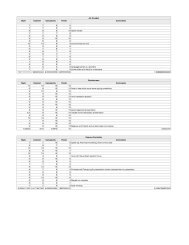
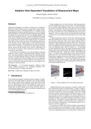
Figure 5: Complete brute forcer second version<br />
called Blank, active high when one of the sync signals are outside of the visual<br />
area. Inside the controller there are also two signals keeping track of the current<br />
relative position on the screen, h_count and v_count. These are used by logic<br />
connected to the controller when displaying images on a certain part of the<br />
screen. In this project these signals are connected to the character generator.<br />
This component has divided the screen into larger tiles, 8x16 pixels large, and<br />
when a new tile is reached by the pixel counters (calculated by dividing the<br />
counters by 8 and 16) the generator calls upon this position in a memory where<br />
the character currently located in each tile is stored and retrieves the value.<br />
This value is then sent to a font memory holding the actual appearance of each<br />
character and the pixel value for the current pixel is masked out and displayed<br />
on the screen. This is done continuously at 60 frames per second, meaning that<br />
the entire screen is redrawn 60 times each second.<br />
The VGA controller in this project is made up of ve main parts, see gure<br />
7. Connecting the entire controller and making it accessible from the Microblaze<br />
processor is a GPU Top that was generated from Xilinx Core Generator and<br />
modied to t the needed preferences. The communication with the Microblaze<br />
processor is done through a PLB bus 32 bits wide. Inside this top is a character<br />
memory and a VGA controller and a memory controller.<br />
4.2 Components<br />
4.2.1 VGA controller<br />
The VGA controller is connected to the VGA port on the FPGA board through<br />
external ports and continuously generates the horizontal and vertical syncsignals<br />
needed by the screen. The controller generates signals at 25 MHz, close<br />
enough to the 25.175 MHz really needed. It also generates the RGB signals<br />
actually displayed on the screen. The sync-signals are generated independently<br />
from the rest of the signals and their implementation comes from the ready-made<br />
VGA controller found on the course home page.<br />
9