SHA1 decoder EDA385
SHA1 decoder EDA385
SHA1 decoder EDA385

You also want an ePaper? Increase the reach of your titles
YUMPU automatically turns print PDFs into web optimized ePapers that Google loves.
<strong>SHA1</strong> <strong>decoder</strong><br />
<strong>EDA385</strong><br />
Erik Hogeman, ada09eho@student.lu.se<br />
Niklas Hjern, ael09nhj@student.lu.se<br />
Jonas Vistrand, ael09jvi@student.lu.se<br />
October 31, 2013
1 Abstract<br />
This report describes a project implementing a hardware accelerated <strong>SHA1</strong><br />
<strong>decoder</strong>. The main idea is for a user to contol the device with a keyboard and the<br />
results and instructions to be output on a VGA display. The project was built<br />
and tested on a Nexys3 using a PLB bus and Microblaze processor. Further, a<br />
pre-constructed ps2 controller, bram and some non-volatile pcm memory were<br />
used.<br />
Custom cores includes a <strong>SHA1</strong> hasher, string generator for brute forcing,<br />
VGA controller and fsl interface. The end result uses 3 parallel <strong>SHA1</strong> hashers<br />
and can compute approximately 6.5 million hashes each second. A dictionary<br />
prestored in the non-volatile memory was also implemented. The end result is<br />
a complete and functional system, very similar to what was intended from the<br />
start.<br />
1
Contents<br />
1 Abstract 1<br />
2 Introduction 3<br />
3 <strong>SHA1</strong> brute forcer 3<br />
3.1 The <strong>SHA1</strong> algorithm . . . . . . . . . . . . . . . . . . . . . . . . . 3<br />
3.2 The brute forcer . . . . . . . . . . . . . . . . . . . . . . . . . . . 5<br />
3.2.1 W-value generator . . . . . . . . . . . . . . . . . . . . . . 5<br />
3.2.2 Main loop . . . . . . . . . . . . . . . . . . . . . . . . . . . 6<br />
3.2.3 <strong>SHA1</strong>-top . . . . . . . . . . . . . . . . . . . . . . . . . . . 6<br />
3.2.4 String generator . . . . . . . . . . . . . . . . . . . . . . . 7<br />
4 VGA controller 8<br />
4.1 VGA theory and basic idea . . . . . . . . . . . . . . . . . . . . . 8<br />
4.2 Components . . . . . . . . . . . . . . . . . . . . . . . . . . . . . . 9<br />
4.2.1 VGA controller . . . . . . . . . . . . . . . . . . . . . . . . 9<br />
4.2.2 Character memory . . . . . . . . . . . . . . . . . . . . . . 10<br />
4.2.3 Character generator . . . . . . . . . . . . . . . . . . . . . 11<br />
4.2.4 Bus2CharMem . . . . . . . . . . . . . . . . . . . . . . . . 11<br />
4.2.5 Font memory . . . . . . . . . . . . . . . . . . . . . . . . . 11<br />
5 Software 12<br />
5.1 Keyboard Controller . . . . . . . . . . . . . . . . . . . . . . . . . 12<br />
5.2 VGA controller . . . . . . . . . . . . . . . . . . . . . . . . . . . . 12<br />
5.3 Dictionary attacker . . . . . . . . . . . . . . . . . . . . . . . . . . 12<br />
5.4 Bruteforce attacker . . . . . . . . . . . . . . . . . . . . . . . . . . 12<br />
5.5 Memory Requirements . . . . . . . . . . . . . . . . . . . . . . . . 13<br />
6 User manual 13<br />
6.1 User interface . . . . . . . . . . . . . . . . . . . . . . . . . . . . . 13<br />
6.2 Providing the hash . . . . . . . . . . . . . . . . . . . . . . . . . . 13<br />
6.3 Selecting the attack . . . . . . . . . . . . . . . . . . . . . . . . . 13<br />
6.4 Brute force attack . . . . . . . . . . . . . . . . . . . . . . . . . . 13<br />
6.5 Dictionary attack . . . . . . . . . . . . . . . . . . . . . . . . . . . 14<br />
6.6 Uploading word list . . . . . . . . . . . . . . . . . . . . . . . . . . 14<br />
7 Problems 14<br />
7.1 Hardware . . . . . . . . . . . . . . . . . . . . . . . . . . . . . . . 14<br />
7.1.1 Brute forcer . . . . . . . . . . . . . . . . . . . . . . . . . . 14<br />
7.1.2 VGA . . . . . . . . . . . . . . . . . . . . . . . . . . . . . . 15<br />
7.1.3 Area constraints . . . . . . . . . . . . . . . . . . . . . . . 15<br />
7.2 Software . . . . . . . . . . . . . . . . . . . . . . . . . . . . . . . . 15<br />
7.2.1 Keyboard controller . . . . . . . . . . . . . . . . . . . . . 15<br />
7.2.2 Memory requirements . . . . . . . . . . . . . . . . . . . . 15<br />
8 Lessons learned 16<br />
9 Contributions 16<br />
2
2 Introduction<br />
The goal of this project has been to build a standalone hardware accelerated<br />
system for hash-decoding for the purpose of retrieving the plain text of hashed<br />
passwords found online. The system is built to tackle the <strong>SHA1</strong> hash algorithm<br />
and is capable of performing two dierent types of attacks, a brute force attack<br />
where the system tries to hash every possible character combination up to a<br />
certain number of characters to nd a match and a dictionary attack where the<br />
system searches roughly 70.000 pre-stored words. The hash value to decode is<br />
entered into the system by a standard USB keyboard and communication with<br />
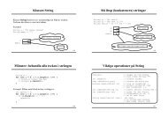
the end user is done by displaying messages on a VGA display. A full overview<br />
of the system can be seen in gure 1. As seen here the system centers around<br />
a Microblaze processor connected to a few dedicated hardware cores. The processor<br />
handles all inputs from the user and controls what is to be displayed on<br />
the VGA display. It also performs the dictionary attack by accessing the PCM<br />
non-volatile memory, where all words are stored through the PLB bus. The<br />
keyboard is controlled by the processor using a readymade polling-based library<br />
and the VGA is controlled by it writing to a certain memory located in the<br />
GPU Top that stores the characters currently being displayed. Both of these<br />
communications are done over the PLB bus. All signals for driving the VGA<br />
display are generated from the custom made VGA core in gure 1 called GPU<br />
Top.<br />
The brute force attack is done in a custom made brute force-core that consists<br />
of two main parts, an encoder and a string generator. The attack is initialized by<br />
the processor sending the hash value entered by the user to the brute force-core<br />
over the FSL bus. The string generator then proceeds to generate all possible<br />
strings for the encoder to encode until a matching value is found, upon which<br />
the result is sent to the processor that displays it on the VGA screen.<br />
The nal realization does not dier that much from the original idea apart<br />
from a few small details. Originally the dictionary attack was to be done in<br />
hardware but this was changed when realizing that it could be implemented<br />
quite easily in software leaving more resources on the FPGA board for a faster<br />
hash encoder for the brute force attack.<br />
3 <strong>SHA1</strong> brute forcer<br />
This section will describe some of the theory behind the <strong>SHA1</strong> algorithm, present<br />
relevant pseudocode examples and explain the dierent parts of the hardware<br />
implementation.<br />
3.1 The <strong>SHA1</strong> algorithm<br />
The hash algorithm chosen for implementation in this project is the so called<br />
<strong>SHA1</strong> hash function. This function is a collision resistant hash function, which<br />
means it is hard to nd two inputs with the same output value. It is built<br />
using the so called Merkle-Damgård construction. This construction is a way<br />
to construct collision resistant hash functions from collision resistant one-way<br />
functions, or more specically if you just use the output from one one-way<br />
function as input to another and chain these together, the whole result will be<br />
3
Figure 1: Overall system architecture<br />
collision resistant as long as the one-way function is. The <strong>SHA1</strong> algorithm uses<br />
this construction, and thus has a loop of size 80 that uses the computed result<br />
from the last iteration each time. In order to decode <strong>SHA1</strong> hashes, a brute force<br />
and a dictionary attack were both implemented.<br />
Pseudo-code for a trimmed version of the algorithm (not supporting strings<br />
over 512 bits) can be found below[3]:<br />
h0 = 0x67452301<br />
h1 = 0xEFCDAB89<br />
h2 = 0x98BADCFE<br />
h3 = 0x10325476<br />
h4 = 0xC3D2E1F0<br />
//Pre-processing:<br />
append the bit '1' to the message<br />
append 0 ≤ k < 512 bits '0', so that the resulting message length<br />
(in bits) is congruent to 448 (mod 512)<br />
append length of message (before pre-processing), in bits, as 64-<br />
bit big-endian integer<br />
//Extend the sixteen 32-bit words into eighty 32-bit words:<br />
for i from 16 to 79<br />
w[i] = (w[i-3] xor w[i-8] xor w[i-14] xor w[i-16])<br />
leftrotate 1<br />
4
Initialize hash value for this chunk:<br />
a = h0<br />
b = h1<br />
c = h2<br />
d = h3<br />
e = h4<br />
//Main loop:<br />
for i from 0 to 79<br />
if 0 ≤ i ≤ 19 then<br />
f = (b and c) or ((not b) and d)<br />
k = 0x5A827999<br />
else if 20 ≤ i ≤ 39<br />
f = b xor c xor d<br />
k = 0x6ED9EBA1<br />
else if 40 ≤ i ≤ 59<br />
f = (b and c) or (b and d) or (c and d)<br />
k = 0x8F1BBCDC<br />
else if 60 ≤ i ≤ 79<br />
f = b xor c xor d<br />
k = 0xCA62C1D6<br />
temp = (a leftrotate 5) + f + e + k + w[i]<br />
e = d<br />
d = c<br />
c = b leftrotate 30<br />
b = a<br />
a = temp<br />
//Produce the final hash value (big-endian):<br />
digest = hash = a append b append c append d append e<br />
3.2 The brute forcer<br />
The two main parts of the brute force related hardware are the string generator<br />
and the actual hardware accelerated <strong>SHA1</strong>-hasher. First, the normal and optimized<br />
version of the <strong>SHA1</strong>-hasher will be explained, then the string generator.<br />
The <strong>SHA1</strong> algorithm can be split into two distinct parts; reading and computing<br />
w-values, and the main loop actually computing the hash. W-values are<br />
named after the w-variable in the pseudocode above, where the initial 16 w-<br />
values are parts of the pre-processed input string. The implementation has also<br />
been split into two dierent hardware cores, explained in more detail below.<br />
3.2.1 W-value generator<br />
This core is in an idle state until a start signal is clocked in with value high,<br />
which triggers the core to start reading 32-bit values on an in-port. These values<br />
represent w[0] to w[15], and one value will be read each clock cycle. After the<br />
5
st value has been read, the core will immediately start clocking out 32-bit<br />
output values for the main loop. Waiting until all values have been read would<br />
be a huge waste of clock cycles, so the output starts the clock cycle after the<br />
input has begun. After clock cycle 16, the core will not read anything more on<br />
the input, but will move to another state and start computing and outputting<br />
w[16]-w[79]. Since the computations involve references to w:s computed 16 clock<br />
cycles earlier, a 16 · 32 = 512 bit shift register must be used to remember the 16<br />
latest computed w-values. This does waste some hardware, but is unavoidable.<br />
The point is that the main loop shall run in parallel as this core, in order<br />
to not waste any clock cycles. After all the values have been output, the core<br />
returns to idle state to await another start signal.<br />
3.2.2 Main loop<br />
This core also waits for a high start signal before it moves from the idle state.<br />
Once such a signal has been found, the 32-bit w-values are being read one each<br />
clock cycle, followed by the necessary computations each round. After a total<br />
amount of 80 clock cycles, which is the same as the amount of iterations, the<br />
main loop will output the 160 bit hash value. Since the main loop and w-value<br />
generator are run in parallel, a complete hash value can be computed in 80 clock<br />
cycles.<br />
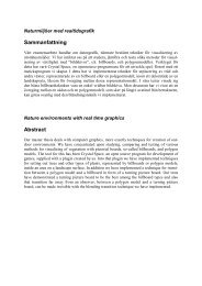
3.2.3 <strong>SHA1</strong>-top<br />
The w-value generator and main loop are both connected to each other using<br />
a top-module. The 16 rst w-values (one value at a time is clocked in) and a<br />
start signal are used as input to this module, and 80 cycles later the hash value<br />
will appear on the output, together with a signal signaling that there is a new<br />
value to be read. The rst version can be seen in gure 2.<br />
Figure 2: <strong>SHA1</strong> hasher rst version<br />
An obvious way of optimizing hardware is to increase the clock frequency if<br />
the longest combinatorial path allows for it. When we synthesized the <strong>SHA1</strong>-<br />
6
hasher, we noticed that our longest combinatorial path had some leeway even<br />
when using the maximum clock frequency that we could choose during the<br />
Nexys3 project building. Thus we decided to do the opposite in order to speed<br />
up our design, in other words make the longest combinatorial path longer. This<br />
way more can be computed each clock cycle, reducing the number of cycles<br />
required.<br />
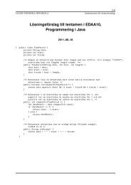
To do this, we increased the input to the w value generator to 64 bits, instead<br />
reading two w-values at a time each cycle. We also created two instances of<br />
the main loop, both connected together in one long combinatorial path, thus<br />
basically unrolling the main loop. With this, the clock cycles required went down<br />
to 40 instead of 80, making each hasher twice as fast. Our longest combinatorial<br />
path was now a little bit longer than the timing constraints seemed to allow in<br />
theory, but in practice it has computed the correct result every time so far so<br />
the optimization has been kept. An image of the optimized version can be seen<br />
in gure 3.<br />
Figure 3: <strong>SHA1</strong> hasher second version<br />
3.2.4 String generator<br />
The basic function of the string generator is to generate all possible strings<br />
of a specic length combined of all letters (small and capital) and numbers.<br />
It achieves this by simulating recursion using a variable keeping track of the<br />
current recursion depth, and a shift register with the current letters in the<br />
current string (which contains the same number of letters as the current depth).<br />
Each clock cycle, a new letter is added, changed or removed depending on the<br />
current depth and the letter at the top of the shift register. To make the design<br />
easy, the communication with the hasher was also done in this core, and the<br />
strings generated was directly generated on the form required for input to the<br />
<strong>SHA1</strong>-hasher.<br />
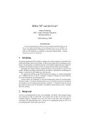
Thus every time a new string was computed, the core also moves to a new<br />
state and start feeding the <strong>SHA1</strong>-top with 32 bit w-values. Then it waits until<br />
the hasher is done, and compares the computed hash value with a reference<br />
7
hash input to it. If the values match, the current string is output. Otherwise,<br />
one clock cycle is spent computing the next string, and then the feeding process<br />
restarts. An image of this version can be seen in gure 4.<br />
Figure 4: Complete brute forcer rst version<br />
Since the string generator spends a lot of time waiting, it could be using that<br />
time to compute the next string and start feeding that to another hasher. We<br />
implemented this, and thus created several <strong>SHA1</strong>-tops in a single string generator.<br />
This required saving several strings at the same time, which introduced<br />
some new hardware in the generator. The hasher was also updated to wait for<br />
conrmation after outputting its hash, to make sure the string generator doesn't<br />
miss it. The new loop for the string generator now instead became to compute a<br />
string, feed it to a hash if there is one not working, and then repeat. If there at<br />
some point is no free hasher working, the generator goes to a waiting state, and<br />
each clock cycle checks for a new free hasher. When there is one, the feeding<br />
process restarts. An image of the optimized version can be seen in gure 5.<br />
We could t 3 optimized 40-cycle hashes on the Spartan 6-board before the<br />
hardware was overused. A VGA-controller and some other things also shared the<br />
hardware though, which limited the number of hashes we could use a bit. Since<br />
the frequency is 88MHz, we can compute approximately 3·88·1000·1000<br />
40<br />
= 6600000<br />
hashes each second.<br />
4 VGA controller<br />
4.1 VGA theory and basic idea<br />
The VGA screen needs two types of signals to be able to display images. Two<br />
sync signals, one horizontal and one vertical, are used to keep track of the current<br />
position on the screen. A gure demonstrating the horizontal sync signal can<br />
be seen in gure 6. As we can see the screen has so called porches used to<br />
retrace the sync signals when the end of the screen is reached. During this<br />
time nothing is displayed and this is controlled by a signal in the controller<br />
8
Figure 5: Complete brute forcer second version<br />
called Blank, active high when one of the sync signals are outside of the visual<br />
area. Inside the controller there are also two signals keeping track of the current<br />
relative position on the screen, h_count and v_count. These are used by logic<br />
connected to the controller when displaying images on a certain part of the<br />
screen. In this project these signals are connected to the character generator.<br />
This component has divided the screen into larger tiles, 8x16 pixels large, and<br />
when a new tile is reached by the pixel counters (calculated by dividing the<br />
counters by 8 and 16) the generator calls upon this position in a memory where<br />
the character currently located in each tile is stored and retrieves the value.<br />
This value is then sent to a font memory holding the actual appearance of each<br />
character and the pixel value for the current pixel is masked out and displayed<br />
on the screen. This is done continuously at 60 frames per second, meaning that<br />
the entire screen is redrawn 60 times each second.<br />
The VGA controller in this project is made up of ve main parts, see gure<br />
7. Connecting the entire controller and making it accessible from the Microblaze<br />
processor is a GPU Top that was generated from Xilinx Core Generator and<br />
modied to t the needed preferences. The communication with the Microblaze<br />
processor is done through a PLB bus 32 bits wide. Inside this top is a character<br />
memory and a VGA controller and a memory controller.<br />
4.2 Components<br />
4.2.1 VGA controller<br />
The VGA controller is connected to the VGA port on the FPGA board through<br />
external ports and continuously generates the horizontal and vertical syncsignals<br />
needed by the screen. The controller generates signals at 25 MHz, close<br />
enough to the 25.175 MHz really needed. It also generates the RGB signals<br />
actually displayed on the screen. The sync-signals are generated independently<br />
from the rest of the signals and their implementation comes from the ready-made<br />
VGA controller found on the course home page.<br />
9
Figure 6: Synchronization diagram for horizontal sync signal[2]<br />
4.2.2 Character memory<br />
The character memory is based on an open source memory[1], and modied to<br />
t the project. It consists of 128x32 8 bit values each representing a character<br />
on the screen. The screen is divided into 80x30 tiles, each tile 8x16 pixels large<br />
and each holding one character. The 8 bit value in the character memory is the<br />
font code for the character currently being displayed in that part of the screen,<br />
a font code that is later used to retrieve the actual pixel composition of the<br />
character. This character memory is read from the Character generator inside<br />
the VGA controller and written to from the Microblaze processor. Software<br />
in the processor keeps track of the current screen position and when messages<br />
are to be output to the user it writes the correct font code of this character in<br />
the correct memory location with a 32 bit message where the rst 12 bits are<br />
position data, the following 8 bits the font code and the last 12 bits are lled<br />
with zeroes.<br />
10
Figure 7: Schematics of VGA controller<br />
4.2.3 Character generator<br />
This component reads an 8 bit value from the character memory and uses this<br />
value as a read address from the font memory. The last 4 bits needed by the<br />
font memory as an address are the y pixel count based on the current position<br />
in the tile, 0 to 15. The received value from the font memory is an 8 bit<br />
vector containing the pixel values for the 8 pixels in the current y position of<br />
the tile. The correct pixel value is then masked out using a counter and the<br />
character generator outputs a single pixel value to the VGA controller. The<br />
character generator is controlled from the VGA controller through a pixel clock<br />
only active when the sync-signals are in the active positions of the screen. The<br />
two memories have a one clock cycle read delay, meaning that the pixel signal<br />
output to the screen is oset three pixels to the right.<br />
4.2.4 Bus2CharMem<br />
This is the memory controller that takes signals from the PLB bus and connects<br />
them to the character memory. All signals necessary for the PLB bus such as<br />
acknowledgements are asserted by this component. It rst checks that the write<br />
address on the bus is equal to that dened as the address of the character<br />
memory and then takes the input signals and writes the correct value in the<br />
correct location of the memory.<br />
4.2.5 Font memory<br />
The font memory is taken in its entirety from an open source project[1] and is<br />
built to take as input a 12 bit address that consists of a font code that is the<br />
base address to the wanted character and a vertical oset that goes from 0 to<br />
15. The memory outputs an 8 bit vector holding the pixel values of the part of<br />
the character indicated by the vertical oset.<br />
11
5 Software<br />
The software on this system is run on simple polling mechanisms. When the<br />
system starts the user is greeted by a greeting screen while the system waits<br />
for an enter key input from the keyboard, which also is polling based. This is<br />
becaue the system will always know when it wants the user to input information<br />
to it. The program then lets the user input a hash value and it will only except<br />
hash values of correct size (40 hexadecimal number). The user is then presented<br />
with the choice to perform a dictionary or a brute force attack. If the brute<br />
force attack is selected the program will ask the user to input the maximum<br />
size of the password which hash value that is going to be decoded. If one of<br />
the attacks is chosen and it fails to retrieve the plain text of the hash the other<br />
attack choice will become available. When the correct plain text is found or<br />
both of the attacks have been performed on the hash the user can choose to try<br />
and decode another hash value or to terminate the program.<br />
5.1 Keyboard Controller<br />
The keyboard communication is done through PLB and is as mentioned above<br />
polling based. The input characters are all converted to ascii and saved in a<br />
string. This string is then printed to the VGA screen and saved on the heap to<br />
allow for processing further down the line.<br />
5.2 VGA controller<br />
The software part of the VGA controller consists mainly of the function<br />
vga_print_string(), which is designed as a general function to be used as the<br />
single method of writing to the screen, be it a single letter when writing on<br />
the keyboard or an entire string as a message to the user. The function reads<br />
the string from the input and calls on the function gen_font_code() for each<br />
character in the string to generate the correct font code for that character. The<br />
function gen_font_code adds the x_count and y_count values to the 8 bit font<br />
code of the current character.<br />
5.3 Dictionary attacker<br />
The dictionary consists of the ten thousand most common passwords and an<br />
english word list. These words and their corresponding hashes are stored in the<br />
FPGA:s non volatile memory. The dictionary attacker simply iterates through<br />
the hashes stored in the memory until one of them matches the hash we want<br />
to decode. The memory address of the hash is saved so that the program can<br />
iterate over the plain text words in the memory until the word with the same<br />
address is found, thus retrieving the plain text. All communication with the<br />
memory is done with a PLB interface.<br />
5.4 Brute force attacker<br />
After the user has provided the hash value and the maximum size of the password,<br />
the hash is converted from a string to hexadecimal values. These hash<br />
values is then sent 32 bits at a time with FSL to the brute force IP core. When<br />
12
the entire hash has been sent the program will wait for either the brute forcer<br />
to return the plain text or until the brute forcer has gone through all possible<br />
password combinations and returns the plain text zero.<br />
5.5 Memory Requirements<br />
All the software on this system needs to be stored on a minimum of 32 kb block<br />
ram.<br />
6 User manual<br />
6.1 User interface<br />
The user interface includes the VGA screen and the keyboard. The VGA screen<br />
will at all times provide the user with instructions. All the user input is done<br />
with a PS2 keyboard.<br />
6.2 Providing the hash<br />
The program will ask the user to input the hash value on which the attack is<br />
to be performed on. This hash value need to be of type <strong>SHA1</strong> and it is always<br />
40 hexadecimal digits long. The program will tell the user if the hash value<br />
is not of the correct size but not if it is the wrong format or if it's containing<br />
non hexadecimal characters. Providing an incorrect hash will not lead to an<br />
error in the execution, the only result will be that no plain text is found in<br />
either the brute force or dictionary attack. If the hash is of the wrong size<br />
however the user will simply be asked to input the hash again. An important<br />
side note is that the <strong>decoder</strong> does not provide support for passwords containing<br />
special characters, only lower- and uppercase letters of the english alphabet and<br />
numbers are supported.<br />
6.3 Selecting the attack<br />
After inputing the hash value, the user will be presented with the choice of<br />
performing a brute force or a dictionary attack. No matter what choice is made,<br />
if the attack comes up empty handed the user will get the chance to perform<br />
the other attack on the same hash value. If the user provides a non valid input<br />
the program will simply let the user input another value until the input is in<br />
the correct format.<br />
6.4 Brute force attack<br />
When the brute force attack is selected the program will ask the user to specify<br />
the maximum length of the password that we have obtained the hash value for.<br />
The program will allow a size up to 7 characters but a size larger than 6 is not<br />
feasible since the number of possible plain text combinations are too large for<br />
the program to have time to go through them all in a reasonable amount of<br />
time. In fact a password of 6 characters will in a worst case scenario take 2 h<br />
and 20 min to decode. If the attack is successful the plain text will be printed<br />
on the screen but if it is unsuccessful the user will be asked if the system should<br />
13
perform a dictionary attack on the hash instead. The user can also choose to<br />
terminate the program or to get the opportunity to input another hash value to<br />
try and decode.<br />
6.5 Dictionary attack<br />
When the dictionary attack is chosen it will start going through the pre-stored<br />
database of words immediately. If the password under attack is one of the ten<br />
thousand most common passwords or a lowercase word in the english dictionary,<br />
the hash will be decoded. If the attack is successful the user will get the chance to<br />
restart the program and if it's unsuccessful a brute force attack can be performed<br />
on the same hash value instead.<br />
6.6 Uploading word list<br />
The FPGA comes pre-loaded with the ten thousand most common passwords<br />
and an english word list with sixty thousand words and their respective hash<br />
values. If the user wishes to upload their own word list this is done by uploading<br />
a ANSI encoded .txt le containing the words seperated by a new line character<br />
to the memory address 0x87000000 (start address of the non volatile memories).<br />
The corresponding hash values are uploaded in the same fashion but to the<br />
memory address 0x87100000 instead. The uploading is done with Adept under<br />
the memory tab. Choose the bpi interface and upload the les starting with the<br />
oset 0 (plain text) and 100000 (hash values).<br />
7 Problems<br />
7.1 Hardware<br />
The rst problem encountered was how to make custom IP cores communicate<br />
with the microblaze processor and what bus system to use. After discovering<br />
that there already was an existing PS2 keyboard controller with a PLB interface<br />
it was decided that the system would use PLB.<br />
7.1.1 Brute forcer<br />
The main problem with implementing the brute forcer was to keep hardware<br />
usage to a minimum. Some problems were very hard to solve without using<br />
quite a bit of new hardware. In the start, only one hasher could be used before<br />
the hardware overowed. This was because a gigantic shift register was used<br />
in the string generator to support very long strings. We decided that only 7<br />
characters were feasible in reality using our design, and thus trimmed this shift<br />
register to only support those 7. This decreased the hardware enough to allow<br />
for 2, almost 3 hashes.<br />
A big cluster of if and case statements were also initially used to append the<br />
bit 1 required for string preprocessing before sending it to the hasher, which<br />
also wasted a lot of hardware. This was nally solved by simply putting this<br />
bit at the top of the shift register in the beginning instead, which automatically<br />
keeps it at the correct position. This decreased the hardware usage enough to<br />
14
allow for a third hash. To support a fourth hash would require more hardware<br />
or a completely new, smarter design.<br />
7.1.2 VGA<br />
A big problem faced was when trying to read from the character memory from<br />
the Microblaze processor. Writing to the memory was never a problem but<br />
when trying to read values from the memory to be able to create a scrolling<br />
eect with the text on the screen some very strange and undened behaviour<br />
occurred. The hardware was modied to also contain a component similar to<br />
the already present Bus2CharMem to function as a read-controller for the bus.<br />
However, due to reasons unknown this never worked as planned and as the idea<br />
was mostly a fun feature from the start this was dropped in favour of working<br />
to optimize the hash-cores.<br />
7.1.3 Area constraints<br />
At rst not much attention was payed to the area constraints of the FPGA board<br />
which lead to a non optimized <strong>SHA1</strong> hasher that took a lot of the available LUT<br />
slices. A lot of optimizing was done to the rst implementation of the algorithm<br />
to allow for more to be placed on the FPGA board.<br />
7.2 Software<br />
One problem was how to nd out which commands in C that would communicate<br />
with the IP cores in the hardware architecture and also what les to include<br />
to enable these commands. This was a recurring problem but after a time of<br />
searching the authors were able to gure it out. Approximately half way into<br />
the projects when when the system rst started to come together the excessive<br />
usage of strings in the code lead to memory leaks and undened behaviour of<br />
the system. This was xed by thoroughly going through the code and freeing<br />
all of the allocated memory.<br />
7.2.1 Keyboard controller<br />
The premade keyboard controller caused a lot of problems in software. Mainly<br />
because it sent a lot of make and break codes instead of just one of each. The<br />
solution contained some workarounds in C which lead to problems later in the<br />
project when sometimes the keyboard didn't read the rst key pressed after the<br />
microblazed had performed an attack on a hash value. This was later solved<br />
with another workaround.<br />
7.2.2 Memory requirements<br />
Not much thought was originally put on how much BRAM the system would<br />
need to store and execute the C code. The size was therefore needed to be<br />
increased two times.<br />
15
8 Lessons learned<br />
The biggest leason learned during this project is to not write hardware implementations<br />
of things that already exists as IP cores in Xilinx. Not doing this<br />
lead to two of the authors dedicating the rst week to writing a keyboard controller<br />
only to discover that one already existed. This knowledge came in handy<br />
when the authors were about to write a memory controller to the non volatile<br />
memories on the FPGA board but checked that there already existed a functioning<br />
ip core with this functionality. Another important discovery was that<br />
the area constraints were much more limiting than imagined, thus not allowing<br />
for as many <strong>SHA1</strong> hashers as wanted.<br />
9 Contributions<br />
• Niklas Hjern:<br />
screen.<br />
Wrote the hardware and software controlling the VGA<br />
• Erik Hogeman: Implemented the <strong>SHA1</strong> hasher and brute force attacker in<br />
hardware. Optimized the <strong>SHA1</strong> algorithm to be as fast and area ecient<br />
as possible.<br />
• Jonas Vistrand: Designed an FSL interface to the brute force attacker and<br />
implemented the dictionary attacker. Wrote software for user interface.<br />
• Testing and assembling of the system was done by all the authors.<br />
References<br />
[1] http://ece320web.groups.et.byu.net/labs/VGATextGeneration/VGA_<br />
Terminal.html Retrieved October 16 2013.<br />
[2] VGA controller reference design from http://www.digilentinc.com/Products/<br />
Detail.cfm?NavPath=2,400,789&Prod=NEXYS2 Retrieved October 16 2013.<br />
[3] http://en.wikipedia.org/wiki/SHA-1 Retrieved October 16 2013.<br />
16