ABB i-bus® EIB 1 x 2-way blind actuator 2-way switch actuator 6172 ...
ABB i-bus® EIB 1 x 2-way blind actuator 2-way switch actuator 6172 ...
ABB i-bus® EIB 1 x 2-way blind actuator 2-way switch actuator 6172 ...

You also want an ePaper? Increase the reach of your titles
YUMPU automatically turns print PDFs into web optimized ePapers that Google loves.
2<br />
2<br />
3<br />
3<br />
4<br />
4<br />
5<br />
5<br />
6<br />
6<br />
2<br />
3<br />
4<br />
5<br />
6<br />
0073-1-6050/24699<br />
1<br />
2<br />
3<br />
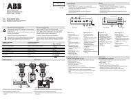
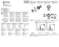
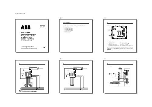
Scope of delivery<br />
Fig. 1<br />
<strong>ABB</strong> i-bus ® <strong>EIB</strong><br />
1 x 2-<strong>way</strong> <strong>blind</strong> <strong>actuator</strong><br />
2-<strong>way</strong> <strong>switch</strong> <strong>actuator</strong><br />
<strong>6172</strong> AG-101-500<br />
GJ B000 6151 A0153<br />
for installation on walls<br />
Operating instructions<br />
Only for qualified electricians with <strong>EIB</strong> training<br />
0073-1-6050<br />
24699<br />
The scope of delivery ex works includes the following components:<br />
- operating instructions<br />
- housing with shutter/series <strong>actuator</strong><br />
- screw/plug-in terminals<br />
- 2 terminals 5-gang (green)<br />
- 2 terminals 4-gang (green)<br />
- 1 terminal 3-gang (green)<br />
- 2 cable entries (closed)<br />
- 1 cable entry (open)<br />
Device view<br />
1<br />
2<br />
3<br />
+ –<br />
X 8<br />
X 1<br />
X 7<br />
X 3<br />
X 2<br />
1 = Programming LED 2 = Programming button<br />
3 = Bus terminal<br />
X 1 = terminal output 1 X 2 = terminal output 2<br />
X 3 = input terminal<br />
X 4 = system overcoupling<br />
X 5 = terminal for pushbutton X 6 = terminal for phase<br />
X 7 = phase selection for output 2 (X2) X 8 = phase selection for output 2 (X1)<br />
CAUTION<br />
The screw/plug-in terminals X 1 - X 5 must be neither inserted nor withdraw<br />
while power is on. Unused plug-in terminals must be clipped on (shock<br />
protection).<br />
X 5<br />
1 7<br />
X 6<br />
X 4<br />
4<br />
5<br />
6<br />
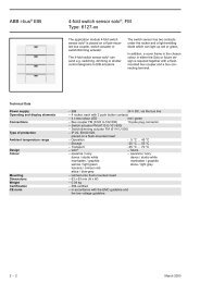
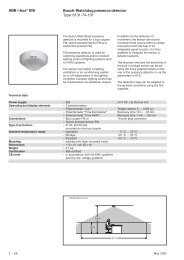
Fig. 2<br />
Fig. 3<br />
Fig. 4<br />
Example of wiring as a 1-gang - 2-<strong>way</strong> <strong>blind</strong> <strong>actuator</strong><br />
Example of wiring as a 2-<strong>way</strong> <strong>switch</strong> <strong>actuator</strong><br />
Internal links<br />
X 5<br />
Pushbutton e.g.<br />
1 x 2020/4 US<br />
X 5<br />
Pushbutton e.g.<br />
2 x 2020 US<br />
1 2 L<br />
X 5<br />
X 8<br />
Jumpers:<br />
X 7 = black<br />
X 8 = brown<br />
X 9 = white<br />
+ –<br />
X 7<br />
1 7<br />
X 6<br />
X 4<br />
Input<br />
X 8<br />
Jumpers:<br />
X 7 = black<br />
X 8 = brown<br />
X 9 = white<br />
+ –<br />
X 7<br />
1 7<br />
X 6<br />
X 4<br />
Input<br />
X 8<br />
X 7<br />
L’<br />
L’’<br />
N<br />
L<br />
L’<br />
L’’<br />
X 4<br />
X 1<br />
M<br />
M<br />
X 3<br />
X 2<br />
X 1<br />
X 3<br />
X 2<br />
Up<br />
X 1<br />
Down N<br />
L<br />
X 6<br />
Up<br />
X 2<br />
Down N<br />
X 3<br />
L’’<br />
L’<br />
L<br />
N<br />
L<br />
N<br />
PE<br />
CAUTION<br />
X7 and X8 must be connected to the same phase!<br />
L<br />
N<br />
PE
0073-1-6050/24699<br />
7<br />
8<br />
9<br />
Important Information<br />
ATTENTION<br />
Work on the 230 V power system may only be performed by qualified<br />
electricians.<br />
DIN-VDE standards and rules, as well as those contained in the <strong>EIB</strong> manual<br />
of the ZVEI/ZVEH, must be adhered to.<br />
The applicable safety requirements (e. g., accident prevention regulations,<br />
"law governing technical equipment") must also be adhered to when<br />
working on connected operating media and installations. For the planning<br />
and erection of electrical installations, the relevant standards, guidelines,<br />
regulations and provisions of that country have to be observed in which the<br />
installation is to be erected and operated.<br />
Please check in any case if these standards and regulations permit<br />
polyphase operation. If polyphase operation is permitted, such a<br />
! wiring system requires an all-pole disconnection of all load and<br />
control lines since there is a danger to life.<br />
Detailed descriptions of application programs and documents to assist planning<br />
are available for planning the installation of the <strong>ABB</strong> i-bus ® in an <strong>ABB</strong> i-bus ® <strong>EIB</strong><br />
system. These documents can be obtained from <strong>ABB</strong>.<br />
The <strong>ABB</strong> manufacturer’s database is constantly updated and contains the latest<br />
applications. Please refer to the Technical Manual for the relevant descriptions.<br />
Should you not have the database and/or the Technical Manual , you can request<br />
these from us.<br />
Device programming is effected with the ETS 2, version 1.1 and higher.<br />
Important Information<br />
When wiring the shutter/series <strong>actuator</strong> <strong>6172</strong> AG-101-500 (hereinafter referred<br />
to as <strong>actuator</strong> <strong>6172</strong> AG-101-500) with incandescent lamps, the instructions of the<br />
lamp/electronic control gear manufacturer regarding making current and power<br />
factor must be adhered to; if necessary, a making current limiter must be used.<br />
ATTENTION<br />
The pushbutton inputs (terminals 1 and 2) must be in phase.<br />
The maximum length of the pushbutton line must not exceed 100 m. Use<br />
only pushbuttons without contact-parallel lighting.<br />
In order to prevent ripple voltage, the connected line must be laid separately<br />
to the pushbutton line.<br />
Fields of Application/Functioning<br />
Function as a shutter <strong>actuator</strong><br />
The <strong>actuator</strong> <strong>6172</strong> AG-101-500 permits the simultaneous control of two shutter<br />
motors. Shuttters can also be raised and lowered and the lamellas adjusted via<br />
conventional shutter pushbuttons (e. g., 2020/4 US). Separate locking (emergency<br />
UP position in the case of high winds) is possible, e. g., via the <strong>ABB</strong> wind sensor.<br />
Function as a series <strong>actuator</strong><br />
The <strong>actuator</strong> <strong>6172</strong> AG-101-500 can <strong>switch</strong> two consumer groups independent of<br />
each other (see also "Technical Data").<br />
Additional functions can be parameterized via the ETS:<br />
- adjustable staircase lighting function<br />
- logic operations (AND/OR)<br />
NOTES<br />
Device selection (shutter or series <strong>actuator</strong>) is effected via the software.<br />
Local operation is possible via conventional pushbuttons.<br />
10<br />
11<br />
12<br />
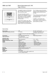
Technical Data<br />
Power supply:<br />
Nominal voltage:<br />
230 V ~ ± 10 % , 50 Hz<br />
Current consumption: ≤ 20 mA<br />
Switching current:<br />
Shutter acutator mode: max. 4 A, cos ϕ = 0.5<br />
Series <strong>actuator</strong> mode: max. 2 x 10 A, cos ϕ = 0.5 (in polyphase operation)<br />
max. 10 A, cos ϕ = 0.5 (in single-phase operation)<br />
Pushbuttons:<br />
Max. line length:<br />
100 m per pushbutton input<br />
No. of pushbuttons (unlit): unlimited<br />
Pushbutton input: 230 V ~ ± 10 % , 50 Hz<br />
Connections (see Fig. 1):<br />
- <strong>ABB</strong> i-bus ® <strong>EIB</strong>: via 2-pole bus terminal 6182<br />
- Pushbutton input: 3-pole screw/plug-in terminal<br />
- System input: 5-pole screw/plug-in terminal<br />
- System overcoupling: 5-pole screw/plug-in terminal<br />
- Switching outputs: 2 x 4-pole screw/plug-in terminal<br />
phase selection by means of a 7-pole plug-in terminal<br />
- Terminal load: max. 10 A for all N and L terminals<br />
General:<br />
Operating temperature: - 5 to + 45 °C<br />
Storage and transport: - 20 to + 70 °C<br />
Type of protection: IP 54 acc. to EN 60529<br />
Dimensions (h x w x d): 105 x 150 x 50 mm<br />
Weight:<br />
0.4 kg<br />
Instructions ref. to installation/Fig. 5<br />
Please observe the following points prior to and during installation:<br />
- Make sure that neither persons nor things are standing in the travelling<br />
range of the shutters, etc.<br />
- The <strong>switch</strong>ing of three-phase loads (e. g., motors) is forbidden.<br />
- In dry locations, the device can be installed on walls as well as on ceilings. In<br />
damp locations, only a vertical installation on walls is permitted (water drain on<br />
the bottom).<br />
- If the device is to be installed on an intermediate ceiling or in a cabinet,<br />
sufficient cooling has to be ensured.<br />
Fig. 5: Location and distance of the bores/drain openings<br />
119 Ø 4,0<br />
81a<br />
Installation<br />
You should in any case read the "Important Information" chapter at the beginning<br />
of these operating instructions.<br />
ATTENTION<br />
De-energize all connecting lines to be installed! Take safety precautions<br />
against an unintentional energizing!<br />
Make sure which application has been provided for the <strong>actuator</strong> <strong>6172</strong> AG-101-500.<br />
This allows you to draw conclusions with respect to:<br />
- the wiring of <strong>actuator</strong> outputs and pushbutton inputs<br />
- parameterization<br />
- the procedure upon commissioning.<br />
ATTENTION<br />
Severe damage may occur, if the wiring of the outputs is not conforming<br />
with the use and the parameterization of the device.<br />
Commissioning must not be effected, unless<br />
- all connections have been laid, made and checked<br />
- all screw/plug-in terminals, even the unwired ones, have been slipped on.<br />
Installation<br />
• Remove the housing cover of the device.<br />
Inside the housing, you will find the connections of the <strong>actuator</strong> <strong>6172</strong> AG-101-500<br />
and another cover. This inner cover remains in its position; during installation,<br />
there is no need to remove this cover (except for "phase selection").<br />
• Mark the bore holes for fixing the housing (see Fig. 5).<br />
The diameter of bores in the housing is 4.0 mm.<br />
• For wall installation, pierce the drain opening positioned below on the rear side<br />
of the housing (see Fig. 5, pos. a).<br />
• Mount the <strong>actuator</strong> <strong>6172</strong> AG-101-500 at the place provided.
X 1<br />
X 5<br />
X 2<br />
X 4<br />
X 3<br />
0073-1-6050/24699<br />
13<br />
14<br />
15<br />
Installation<br />
Connection<br />
• Unless you have done this already before, lay the connecting lines now<br />
- for the connected electrical consumers or shutter motors<br />
- for the pushbutton inputs<br />
When using <strong>actuator</strong> outputs for a shutter control, the pushbuttons for the<br />
(optional) local operation must be designed as shutter pushbuttons.<br />
ATTENTION<br />
Observe the national standards and regulations governing polyphase operation:<br />
- if the voltage for contact interrogation is provided externally by another phase<br />
- if the voltage supply of the <strong>actuator</strong> outputs is effected via several different<br />
phases.<br />
• Before connecting the connecting line(s) to a screw/plug-in terminal, remove<br />
the damp-proof cable gland from the housing and slide it over the ends of the<br />
connecting line(s).<br />
• Strip off approx. 7 mm of the insulation from the connecting line(s) and fix the<br />
bare cable ends in the provided contacts of the screw/plug-in terminal by<br />
screwing.<br />
ATTENTION<br />
Thereby, observe the location and orientation of the pin names at the pushon<br />
terminal strips!<br />
• Position the damp-proof housing cover at an appropriate distance from the<br />
screw/plug-in terminal and push terminal and cable gland into the provided<br />
recesses at the same time. Ensure that no kinks are formed in the connecting<br />
lines.<br />
ATTENTION<br />
The screw/plug-in terminal must snap into place perceptibly in order to<br />
make a reliable connection. Ensure that the screw/plug-in terminals are in<br />
a straight position in the lower part!<br />
Installation<br />
• After all connections have been made and checked, place the unused screw/<br />
plug-in terminals on the associated free locations (shock protection!).<br />
• Close all unused housing openings by means of the supplied closed cable<br />
gands.<br />
• Do not fix the housing cover unless a physical address has been assigned<br />
during commissioning.<br />
Up to this time the power supply must not be <strong>switch</strong>ed on!<br />
Installation: phase selection<br />
ATTENTION<br />
Ensure that all connecting lines to be mounted are still de-energized! Take<br />
safety precautions against an unintentional energizing!<br />
By means of the 7-pole plug-in terminal and the three connecting wires (coloured,<br />
flexible), the Powernet <strong>EIB</strong> path and the two outputs can be randomly assigned<br />
to the input phases (in case of polyphase wiring). The connecting wires are preconfigured<br />
ex works to L ( L1) by means of the plug-in terminal.<br />
Depending on the load conditions, it is possible to reconnect the relays to L‘ ( L2)<br />
or L‘‘ ( L3), respectively.<br />
ATTENTION<br />
When the device is used as a shutter <strong>actuator</strong>, the two lines X7 (black) and<br />
X8 (brown) must only be connected to the same phase.<br />
Reconnection of the connecting wires<br />
ATTENTION<br />
Switch off the power supply before loosening the inner cover. The cover<br />
may only be removed by authorized electricians in acc. with VDE 0100 and<br />
TAB!<br />
• Loosen the two screws (diagonally<br />
1<br />
opposite - see pos. 1) of the inner cover<br />
and withdraw all screw/plug-in terminals.<br />
• Lift off the cover carefully.<br />
• Reconnect the connecting wires as<br />
described above.<br />
1<br />
• Then immediately replace and fasten the<br />
cover.<br />
16<br />
17<br />
Installation: phase selection<br />
ATTENTION<br />
The preferred state of the output relay (in the case of failure or restoration of the<br />
voltage supply of the <strong>actuator</strong> <strong>6172</strong> AG-101-500) is set ex Works to OFF. This<br />
preferred state can be changed via the ETS.<br />
In this case, ensure that the system is not in an undesired or dangerous<br />
operating state when the voltage supply is connected/<strong>switch</strong>ed off.<br />
Commissioning<br />
• Fasten the cover prior to commissioning.<br />
Operation of the device is software-dependent. In order to effect programming,<br />
connect a PC with the ETS 2, version 1.1 or higher, to the <strong>ABB</strong> i-bus ® <strong>EIB</strong> bus line<br />
via an <strong>EIB</strong>-RS 232 interface.<br />
Allocation of the Physical Address<br />
• Switch on the supply voltage.<br />
• Load the physical address and the application in <strong>actuator</strong> <strong>6172</strong> AG-101-500 via<br />
the ETS.<br />
• For this purpose, press the programming key on the device.<br />
- The red programming LED illuminates.<br />
• The red LED extinguishes after the physical address has been programmed.<br />
• Note the number of the physical address on the device, if appropriate, using a<br />
non-smudge pen.<br />
Selection/Parameterization of the Application<br />
Please refer to the current Technical Manual for a description of the available<br />
application versions and appurtenant parameters.