

X5R Dielectric LD Series Tin/Lead Terminations - AVX
X5R Dielectric LD Series Tin/Lead Terminations - AVX
X5R Dielectric LD Series Tin/Lead Terminations - AVX

You also want an ePaper? Increase the reach of your titles
YUMPU automatically turns print PDFs into web optimized ePapers that Google loves.
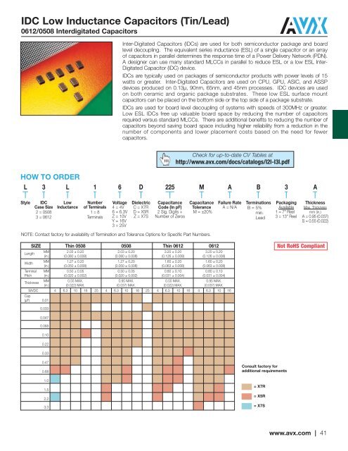
IDC Low Inductance Capacitors (<strong>Tin</strong>/<strong>Lead</strong>)<br />
0612/0508 Interdigitated Capacitors<br />
Inter-Digitated Capacitors (IDCs) are used for both semiconductor package and board<br />
level decoupling. The equivalent series inductance (ESL) of a single capacitor or an array<br />
of capacitors in parallel determines the response time of a Power Delivery Network (PDN).<br />
A designer can use many standard MLCCs in parallel to reduce ESL or a low ESL Inter-<br />
Digitated Capacitor (IDC) device.<br />
IDCs are typically used on packages of semiconductor products with power levels of 15<br />
watts or greater. Inter-Digitated Capacitors are used on CPU, GPU, ASIC, and ASSP<br />
devices produced on 0.13μ, 90nm, 65nm, and 45nm processes. IDC devices are used<br />
on both ceramic and organic package substrates. These low ESL surface mount<br />
capacitors can be placed on the bottom side or the top side of a package substrate.<br />
IDCs are used for board level decoupling of systems with speeds of 300MHz or greater.<br />
Low ESL IDCs free up valuable board space by reducing the number of capacitors<br />
required versus standard MLCCs. There are additional benefits to reducing the number of<br />
capacitors beyond saving board space including higher reliability from a reduction in the<br />
number of components and lower placement costs based on the need for fewer<br />
capacitors.<br />
Check for up-to-date CV Tables at<br />
http://www.avx.com/docs/catalogs/l2l-l3l.pdf<br />
HOW TO ORDER<br />
L 3 L<br />
1<br />
6<br />
D<br />
225<br />
M<br />
A<br />
B<br />
3<br />
A<br />
Style<br />
IDC<br />
Case Size<br />
2 = 0508<br />
3 = 0612<br />
Low<br />
Inductance<br />
Number<br />
of Terminals<br />
1 = 8<br />
Terminals<br />
Voltage<br />
4 = 4V<br />
6 = 6.3V<br />
Z = 10V<br />
Y = 16V<br />
3 = 25V<br />
<strong>Dielectric</strong><br />
C = X7R<br />
D = <strong>X5R</strong><br />
Z = X7S<br />
Capacitance<br />
Code (In pF)<br />
2 Sig. Digits +<br />
Number of Zeros<br />
Capacitance<br />
Tolerance<br />
M = ±20%<br />
Failure Rate<br />
A = N/A<br />
<strong>Terminations</strong><br />
B = 5%<br />
min.<br />
<strong>Lead</strong><br />
Packaging<br />
Available<br />
1 = 7" Reel<br />
3 = 13" Reel<br />
Thickness<br />
Max. Thickness<br />
mm (in.)<br />
A = 0.95 (0.037)<br />
S = 0.55 (0.022)<br />
NOTE: Contact factory for availability of Termination and Tolerance Options for Specific Part Numbers.<br />
SIZE Thin 0508 0508 Thin 0612 0612<br />
Length<br />
MM 2.03 ± 0.20 2.03 ± 0.20 3.20 ± 0.20 3.20 ± 0.20<br />
(in.) (0.080 ± 0.008) (0.080 ± 0.008) (0.126 ± 0.008) (0.126 ± 0.008)<br />
Width<br />
MM 1.27 ± 0.20 1.27 ± 0.20 1.60 ± 0.20 1.60 ± 0.20<br />
(in.) (0.050 ± 0.008) (0.050 ± 0.008) (0.063 ± 0.008) (0.063 ± 0.008)<br />
Terminal MM 0.50 ± 0.05 0.50 ± 0.05 0.80 ± 0.10 0.80 ± 0.10<br />
Pitch (in.) (0.020 ± 0.002) (0.020 ± 0.002) (0.031 ± 0.004) (0.031 ± 0.004)<br />
Thickness<br />
MM 0.55 MAX. 0.95 MAX. 0.55 MAX. 0.95 MAX.<br />
(in.) (0.022) MAX. (0.037) MAX. (0.022) MAX. (0.037) MAX.<br />
WVDC 4 6.3 10 16 25 4 6.3 10 16 25 4 6.3 10 16 4 6.3 10 16<br />
Cap<br />
(μF) 0.01<br />
Not RoHS Compliant<br />
0.033<br />
0.047<br />
0.068<br />
0.10<br />
0.22<br />
0.33<br />
0.47<br />
0.68<br />
1.0<br />
1.5<br />
2.2<br />
3.3<br />
Consult factory for<br />
additional requirements<br />
= X7R<br />
= <strong>X5R</strong><br />
= X7S<br />
www.avx.com | 41


