

X5R Dielectric LD Series Tin/Lead Terminations - AVX
X5R Dielectric LD Series Tin/Lead Terminations - AVX
X5R Dielectric LD Series Tin/Lead Terminations - AVX

You also want an ePaper? Increase the reach of your titles
YUMPU automatically turns print PDFs into web optimized ePapers that Google loves.
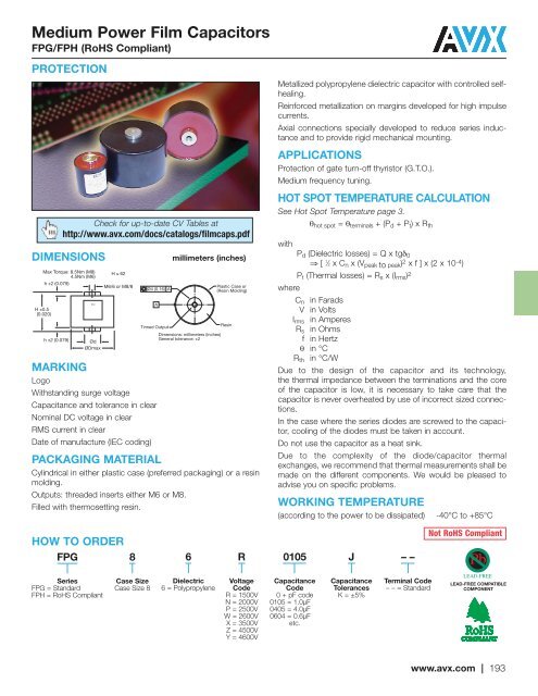
Medium Power Film Capacitors<br />
FPG/FPH (RoHS Compliant)<br />
PROTECTION<br />
DIMENSIONS<br />
Max Torque: 8.5Nm (M8)<br />
4.5Nm (M6)<br />
h ±2 (0.079)<br />
H ±0.5<br />
(0.020)<br />
h ±2 (0.079)<br />
MARKING<br />
Logo<br />
Check for up-to-date CV Tables at<br />
http://www.avx.com/docs/catalogs/filmcaps.pdf<br />
TPC<br />
Ød<br />
ØDmax<br />
H ≤ 62<br />
M6/6 or M8/8<br />
Ø4 (0.16) A<br />
A<br />
<strong>Tin</strong>ned Output<br />
Withstanding surge voltage<br />
Capacitance and tolerance in clear<br />
Nominal DC voltage in clear<br />
RMS current in clear<br />
Date of manufacture (IEC coding)<br />
millimeters (inches)<br />
Dimensions: millimeters (inches)<br />
General tolerance: ±2<br />
Plastic Case or<br />
(Resin Molding)<br />
PACKAGING MATERIAL<br />
Cylindrical in either plastic case (preferred packaging) or a resin<br />
molding.<br />
Outputs: threaded inserts either M6 or M8.<br />
Filled with thermosetting resin.<br />
Resin<br />
Metallized polypropylene dielectric capacitor with controlled selfhealing.<br />
Reinforced metallization on margins developed for high impulse<br />
currents.<br />
Axial connections specially developed to reduce series inductance<br />
and to provide rigid mechanical mounting.<br />
APPLICATIONS<br />
Protection of gate turn-off thyristor (G.T.O.).<br />
Medium frequency tuning.<br />
HOT SPOT TEMPERATURE CALCULATION<br />
See Hot Spot Temperature page 3.<br />
θ hot spot = θ terminals + (P d + P t ) x R th<br />
with<br />
P d (<strong>Dielectric</strong> losses) = Q x tgδ 0<br />
⇒ [ 1 ⁄2 x C n x (V peak to peak ) 2 x f ] x (2 x 10 -4 )<br />
P t (Thermal losses) = R s x (I rms ) 2<br />
where<br />
C n in Farads<br />
V in Volts<br />
I rms in Amperes<br />
R s in Ohms<br />
f in Hertz<br />
θ in °C<br />
R th in °C/W<br />
Due to the design of the capacitor and its technology,<br />
the thermal impedance between the terminations and the core<br />
of the capacitor is low, it is necessary to take care that the<br />
capacitor is never overheated by use of incorrect sized connections.<br />
In the case where the series diodes are screwed to the capacitor,<br />
cooling of the diodes must be taken in account.<br />
Do not use the capacitor as a heat sink.<br />
Due to the complexity of the diode/capacitor thermal<br />
exchanges, we recommend that thermal measurements shall be<br />
made on the different components. We would be pleased to<br />
advise you on specific problems.<br />
WORKING TEMPERATURE<br />
(according to the power to be dissipated)<br />
-40°C to +85°C<br />
HOW TO ORDER<br />
FPG<br />
8<br />
6<br />
R<br />
0105<br />
J<br />
––<br />
Not RoHS Compliant<br />
<strong>Series</strong><br />
FPG = Standard<br />
FPH = RoHS Compliant<br />
Case Size<br />
Case Size 8<br />
<strong>Dielectric</strong><br />
6 = Polypropylene<br />
Voltage<br />
Code<br />
R = 1500V<br />
N = 2000V<br />
P = 2500V<br />
W = 2600V<br />
X = 3500V<br />
Z = 4500V<br />
Y = 4600V<br />
Capacitance<br />
Code<br />
0 + pF code<br />
0105 = 1.0μF<br />
0405 = 4.0μF<br />
0604 = 0.6μF<br />
etc.<br />
Capacitance<br />
Tolerances<br />
K = ±5%<br />
Terminal Code<br />
– – = Standard<br />
LEAD-FREE COMPATIBLE<br />
COMPONENT<br />
www.avx.com | 193


