LM723 - ESR Electronic Components
LM723 - ESR Electronic Components
LM723 - ESR Electronic Components

Create successful ePaper yourself
Turn your PDF publications into a flip-book with our unique Google optimized e-Paper software.
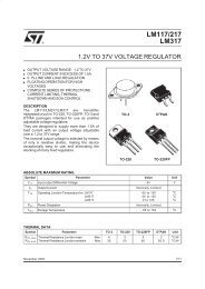
<strong>LM723</strong><br />
HIGH PRECISION VOLTAGE REGULATOR<br />
■<br />
INPUT VOLTAGE UP TO 40V<br />
■ OUTPUT VOLTAGE ADJUSTABLE FROM 2<br />
TO 37V<br />
■ POSITIVE OR NEGATIVE SUPPLY<br />
OPERATION<br />
■ SERIES, SHUNT, SWITCHING OR<br />
FLOATING OPERATION<br />
■ OUTPUT CURRENT TO 150mA WITHOUT<br />
EXTERNAL PASS TRANSISTOR<br />
■ ADJUSTABLE CURRENT LIMITING<br />
DIP-14<br />
DESCRIPTION<br />
The <strong>LM723</strong> is a monolithic integrated<br />
programmable voltage regulator, assembled in<br />
14-lead dual in-line plastic and SO-14 micro<br />
package. The circuit provides internal current<br />
limiting. When the output current exceeds 150mA<br />
an external NPN or PNP pass element may be<br />
used. Provisions are made for adjustable current<br />
limiting and remote shut-down.<br />
SO-14<br />
SCHEMATIC DIAGRAM<br />
September 2003<br />
1/16
<strong>LM723</strong><br />
ABSOLUTE MAXIMUM RATINGS<br />
Symbol<br />
Parameter<br />
<strong>LM723</strong><br />
Value<br />
<strong>LM723</strong>C<br />
Unit<br />
V I DC Input Voltage 40 40 V<br />
∆V I-O Dropout Voltage 40 40 V<br />
I O Output Current 150 150 mA<br />
I REF Current from V REF 15 25 mA<br />
T op Operating Temperature -55to125 0to70 °C<br />
T stg Storage Temperature -65to150 -65to150 °C<br />
T J Junction Temperature 150 125 °C<br />
Absolute Maximum Ratings are those values beyond which damage to the device may occur. Functional operation under these condition is<br />
not implied.<br />
THERMAL DATA<br />
Symbol Parameter DIP14 SO-14 Unit<br />
R thj-amb Thermal Resistance Junction-Ambient Max 200 160 °C/W<br />
PIN CONNECTION (top view)<br />
ORDERING CODES<br />
TYPE DIP-14 SO-14<br />
<strong>LM723</strong><br />
<strong>LM723</strong>N<br />
<strong>LM723</strong>C <strong>LM723</strong>CN <strong>LM723</strong>CD<br />
2/16
<strong>LM723</strong><br />
TEST CIRCUITS (pin configuration relative to the plastic package)<br />
V I =12V;V O =5V:I O =1mA;R 1 /R 2 ≤ 10KΩ<br />
ELECTRICAL CHARACTERISTICS FOR <strong>LM723</strong> (refer to the test circuits, T amb = 25°C,<br />
unless otherwise specified.)<br />
Symbol Parameter Test Conditions Min. Typ. Max. Unit<br />
∆V O /∆V I Line Regulation V I = 12 to 15 V 0.01 0.1 %<br />
V I = 12 to 40 V 0.02 0.2<br />
V I =12to15V, T a = -55 to 125°C 0.3<br />
∆V O /V O Load Regulation I O = 1 to 50 mA 0.03 0.15 %<br />
I O =1to10mA T a = -55 to 125°C 0.6<br />
V REF Reference Voltage I REF = 160 µA 6.95 7.15 7.35 V<br />
SVR Supply Voltage Rejection f = 100 Hz to 10KHz C REF = 0 74 dB<br />
C REF =5µF 86<br />
∆V O /∆T Output Voltage Drift 150 ppm/°C<br />
I SC Output Current Limit R SC =10Ω V O = 0 V 65 mA<br />
V I Input Voltage Range 9.5 40 V<br />
V O Output Voltage Range 2 37 V<br />
V O -V I 3 38 V<br />
I d Quiescent Current V I = 30V, I O = 0 mA 2.3 5 mA<br />
K VH Long Term Stability 0.1 %/1000<br />
hrs<br />
eN Output Noise Voltage BW = 100 Hz to 10 KHz C REF =0 20 µV<br />
C REF = 5µF 2.5<br />
3/16
<strong>LM723</strong><br />
ELECTRICAL CHARACTERISTICS FOR <strong>LM723</strong>C (refer to the test circuits, T amb = 25°C,<br />
unless otherwise specified.)<br />
Symbol Parameter Test Conditions Min. Typ. Max. Unit<br />
∆V O /∆V I Line Regulation V I = 12 to 15 V 0.01 0.1 %<br />
V I = 12 to 40 V 0.1 0.5<br />
V I =12to15V, T a = 0 to 70°C 0.3<br />
∆V O /V O Load Regulation I O = 1 to 50 mA 0.03 0.2 %<br />
I O =1to10mA T a = 0 to 70°C 0.6<br />
V REF Reference Voltage I REF = 160 µA 6.8 7.15 7.5 V<br />
SVR Supply Voltage Rejection f = 100 Hz to 10KHz C REF = 0 74 dB<br />
C REF =5µF 86<br />
∆V O /∆T Output Voltage Drift 150 ppm/°C<br />
I SC Output Current Limit R SC =10Ω V O = 0 V 65 mA<br />
V I Input Voltage Range 9.5 40 V<br />
V O Output Voltage Range 2 37 V<br />
V O -V I 3 38 V<br />
I d Quiescent Current V I = 30V, I O = 0 mA 2.3 4 mA<br />
K VH Long Term Stability 0.1 %/1000<br />
hrs<br />
eN Output Noise Voltage BW = 100 Hz to 10 KHz C REF =0 20 µV<br />
C REF = 5µF 2.5<br />
4/16
<strong>LM723</strong><br />
TYPICAL PERFORMANCE CHARACTERISTICS (unless otherwise specified V O(NOM) =3.3V)<br />
Figure 1 : Maximum Output Current vs Voltage<br />
Drop<br />
Figure 4 : Load Regulation Characteristics<br />
without Current Limiting<br />
Figure 2 : Current Limiting Characteristics<br />
Figure 5 : Load Regulation Characteristics<br />
with Current Limiting<br />
Figure 3 : Current Limiting Characteristics vs<br />
Junction Temperature<br />
Figure 6 : Load Regulation Characteristics<br />
with Current Limiting<br />
5/16
<strong>LM723</strong><br />
Figure 7 : Line Regulation vs Voltage Drop<br />
Figure 10 : Line Transient Response<br />
Figure 8 : Load Regulation vs Voltage Drop<br />
Figure 11 : Load Transient Response<br />
Figure 9 : Quiescent Drain Current vs Input<br />
Voltage<br />
Figure 12 : Output Impedance vs Frequency<br />
6/16
<strong>LM723</strong><br />
TABLE 1: Resistor Values (KΩ) for standard Output Voltages<br />
Output<br />
Voltage<br />
Applicable Figures<br />
* Replace R1/R2 divider with the circuit of fig. 24.<br />
** V+ must be connected to a +3V or greater supply.<br />
TABLE 2: Formula for Intermediate Output Voltages<br />
Fixed Output ± 5% Output Adjustable ± 10% *<br />
R1 R2 R1 P1 R2<br />
+3 13, 16, 17, 18, 21, 23 4.12 3.01 1.8 0.5 1.2<br />
+5 13, 16, 17, 18, 21, 23 2.15 4.99 0.75 0.5 2.2<br />
+6 13, 16, 17, 18, 21, 23 1.15 6.04 0.5 0.5 2.7<br />
+9 14, 16, 17, 18, 21, 23 1.87 7.15 0.75 1 2.7<br />
+12 14, 16, 17, 18, 21, 23 4.87 7.15 2 1 3<br />
+15 14, 16, 17, 18, 21, 23 7.87 7.15 3.3 1 3<br />
+28 14, 16, 17, 18, 21, 23 21 7.15 5.6 1 2<br />
+45 19 3.57 48.7 2.2 10 39<br />
+75 19 3.57 78.7 2.2 10 68<br />
+100 19 3.57 102 2.2 10 91<br />
+250 19 3.57 255 2.2 10 240<br />
-6** 15 3.57 2.43 1.2 0.5 0.75<br />
-9 15 3.48 5.36 1.2 0.5 2<br />
-12 15 3.57 8.45 1.2 0.5 3.3<br />
-15 15 3.65 11.5 1.2 0.5 4.3<br />
-28 15 3.57 24.3 1.2 0.5 10<br />
-45 20 3.57 21.2 2.2 10 33<br />
-100 20 3.57 97.6 2.2 10 91<br />
-250 20 3.57 249 2.2 10 240<br />
Outputs from 2 to 7V<br />
Fig. 13, 16, 17, 18, 21, 23<br />
V O =(V REF xR 2 )/(R 1 +R 2 )<br />
Outputs from 7 to 37V<br />
Fig. 14, 16, 17, 18, 21, 23<br />
V O =V REF x[(R 1 +R 2 )/R 2 ]<br />
Outputs from 4 to 250V<br />
Fig. 19<br />
V O =(V REF /2)x[(R 2 -R 1 )/R 1 ]; R 3 =R 4<br />
Outputs from -6 to -250V<br />
Fig. 15, 20<br />
V O =(V REF /2)x[(R 1 +R 2 )/R 1 ]; R 3 =R 4<br />
Current Limit<br />
I LIMIT =V SENSE /R SC<br />
Foldback Current Limiting<br />
I KNEE =[(V O xR 3 )/(R SC xR 4 )]x[V SENSE x(R 3 +R 4 )]/<br />
(R SC xR 4 )<br />
I SHORTCKT =(V SENSE /R SC )x[(R 3 +R 4 )/R 4 ]<br />
7/16
<strong>LM723</strong><br />
APPLICATIONS INFORMATION<br />
Figure 13 : Basic Low Voltage Regulator (V O =2to7V).<br />
NOTE: R 3 =(R 1 xR 2 )/(R 1 +R 2 ) for minimum temperature drift.<br />
R 3 may be eliminated for minimum component count.<br />
Typical performance<br />
Regulated Output Voltage..................5V<br />
Line Regulation (∆V I = 3V)..........0.5mV<br />
Load Regulation (∆I O = 50mA)...1.5mV<br />
Figure 14 : Basic High Voltage Regulator (V O = 7 to 37V)<br />
NOTE: R 3 =(R 1 xR 2 )/(R 1 +R 2 ) for minimum temperature drift.<br />
R 3 may be eliminated for minimum component count.<br />
Typical performance<br />
Regulated Output Voltage..................15V<br />
Line Regulation (∆V I = 3V)............1.5mV<br />
Load Regulation (∆I O = 50mA).....4.5mV<br />
8/16
<strong>LM723</strong><br />
Figure 15 : Negative Voltage Regulator<br />
Typical performance<br />
Regulated Output Voltage.................15V<br />
Line Regulation (∆V I = 3V)...............1mV<br />
Load Regulation (∆I O = 100mA)......2mV<br />
Figure 16 : Positive Voltage Regulator (External NPN Pass Transistor)<br />
Typical performance<br />
Regulated Output Voltage................15V<br />
Line Regulation (∆V I = 3V)...........1.5mV<br />
Load Regulation (∆I O = 1A)...........15mV<br />
Figure 17 : Positive Voltage Regulator (External PNP Pass Transistor)<br />
Typical performance<br />
Regulated Output Voltage...................5V<br />
Line Regulation (∆V I = 3V)...........0.5mV<br />
Load Regulation (∆I O = 1A)..........1.5mV<br />
9/16
<strong>LM723</strong><br />
Figure 18 : Foldback current limiting<br />
Typical performance<br />
Regulated Output Voltage....................5V<br />
Line Regulation (∆V I = 3V)............0.5mV<br />
Load Regulation (∆I O = 10mA)........1mV<br />
Current Limit Knee...........................20mA<br />
Figure 19 : Positive Floating Regulator<br />
Typical performance<br />
Regulated Output Voltage....................100V<br />
Line Regulation (∆V I = 20V)...............15mV<br />
Load Regulation (∆I O = 50mA)..........20mV<br />
Figure 20 : Negative Floating Regulator<br />
Typical performance<br />
Regulated Output Voltage....................-100V<br />
Line Regulation (∆V I = 20V).................30mV<br />
Load Regulation (∆I O = 100mA)..........20mV<br />
10/16
<strong>LM723</strong><br />
Figure 21 : Positive Switching Regulator<br />
Typical performance<br />
Regulated Output Voltage....................5V<br />
Line Regulation (∆V I = 30V)...........10mV<br />
Load Regulation (∆I O = 2A)............80mV<br />
Figure 22 : Remote Shutdown Regulator with Current Limiting<br />
Note: current limit transistor may be used for shutdown if current limiting is not required.<br />
Typical performance<br />
Regulated Output Voltage...........................5V<br />
Line Regulation (∆V I = 3V)...................0.5mV<br />
Load Regulation (∆I O = 50mA)............1.5mV<br />
Figure 23 : Shunt Regulator<br />
Typical performance<br />
Regulated Output Voltage............................5V<br />
Line Regulation (∆V I = 10V).....................2mV<br />
Load Regulation (∆I O = 100mA)..............5mV<br />
11/16
<strong>LM723</strong><br />
Figure 24 : Output Voltage Adjust<br />
12/16
<strong>LM723</strong><br />
Plastic DIP-14 MECHANICAL DATA<br />
DIM.<br />
mm.<br />
inch<br />
MIN. TYP MAX. MIN. TYP. MAX.<br />
a1 0.51 0.020<br />
B 1.39 1.65 0.055 0.065<br />
b 0.5 0.020<br />
b1 0.25 0.010<br />
D 20 0.787<br />
E 8.5 0.335<br />
e 2.54 0.100<br />
e3 15.24 0.600<br />
F 7.1 0.280<br />
I 5.1 0.201<br />
L 3.3 0.130<br />
Z 1.27 2.54 0.050 0.100<br />
P001A<br />
13/16
<strong>LM723</strong><br />
SO-14 MECHANICAL DATA<br />
DIM.<br />
mm.<br />
inch<br />
MIN. TYP MAX. MIN. TYP. MAX.<br />
A 1.75 0.068<br />
a1 0.1 0.2 0.003 0.007<br />
a2 1.65 0.064<br />
b 0.35 0.46 0.013 0.018<br />
b1 0.19 0.25 0.007 0.010<br />
C 0.5 0.019<br />
c1<br />
45˚ (typ.)<br />
D 8.55 8.75 0.336 0.344<br />
E 5.8 6.2 0.228 0.244<br />
e 1.27 0.050<br />
e3 7.62 0.300<br />
F 3.8 4.0 0.149 0.157<br />
G 4.6 5.3 0.181 0.208<br />
L 0.5 1.27 0.019 0.050<br />
M 0.68 0.026<br />
S<br />
8˚<br />
(max.)<br />
PO13G<br />
14/16
<strong>LM723</strong><br />
Tape & Reel SO-14 MECHANICAL DATA<br />
DIM.<br />
mm.<br />
inch<br />
MIN. TYP MAX. MIN. TYP. MAX.<br />
A 330 12.992<br />
C 12.8 13.2 0.504 0.519<br />
D 20.2 0.795<br />
N 60 2.362<br />
T 22.4 0.882<br />
Ao 6.4 6.6 0.252 0.260<br />
Bo 9 9.2 0.354 0.362<br />
Ko 2.1 2.3 0.082 0.090<br />
Po 3.9 4.1 0.153 0.161<br />
P 7.9 8.1 0.311 0.319<br />
15/16
<strong>LM723</strong><br />
Information furnished is believed to be accurate and reliable. However, STMicroelectronics assumes no responsibility for the<br />
consequences of use of such information nor for any infringement of patents or other rights of third parties which may result from<br />
its use. No license is granted by implication or otherwise under any patent or patent rights of STMicroelectronics. Specifications<br />
mentioned in this publication are subject to change without notice. This publication supersedes and replaces all information<br />
previously supplied. STMicroelectronics products are not authorized for use as critical components in life support devices or<br />
systems without express written approval of STMicroelectronics.<br />
The ST logo is a registered trademark of STMicroelectronics<br />
All other names are the property of their respective owners<br />
© 2003 STMicroelectronics - All Rights Reserved<br />
STMicroelectronics GROUP OF COMPANIES<br />
Australia - Belgium - Brazil - Canada - China - Czech Republic - Finland - France - Germany - Hong Kong - India - Israel - Italy - Japan -<br />
Malaysia - Malta - Morocco - Singapore - Spain - Sweden - Switzerland - United Kingdom - United States.<br />
http://www.st.com<br />
16/16