PDF Download - Glidewell Dental Labs
PDF Download - Glidewell Dental Labs
PDF Download - Glidewell Dental Labs

You also want an ePaper? Increase the reach of your titles
YUMPU automatically turns print PDFs into web optimized ePapers that Google loves.
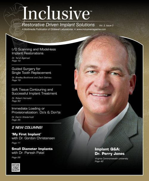
Inclusive<br />
Restorative Driven Implant Solutions Vol. 3, Issue 2<br />
A Multimedia Publication of <strong>Glidewell</strong> Laboratories • www.inclusivemagazine.com<br />
I/O Scanning and Model-less<br />
Implant Restorations<br />
Dr. Tarun Agarwal<br />
Page 13<br />
Guided Surgery for<br />
Single Tooth Replacement<br />
Dr. Bradley Bockhorst and Zach Dalmau<br />
Page 19<br />
Soft Tissue Contouring and<br />
Successful Implant Treatment<br />
Dr. Robert Horowitz<br />
Page 50<br />
Immediate Loading or<br />
Provisionalization: Do’s & Don’ts<br />
Dr. Darrin Wiederhold<br />
Page 35<br />
2 NEW COLUMNS!<br />
‘My First Implant’<br />
with Dr. Gordon Christensen<br />
Page 11<br />
Small Diameter Implants<br />
with Dr. Paresh Patel<br />
Page 26<br />
Implant Q&A:<br />
Dr. Perry Jones<br />
Virginia Commonwealth University<br />
Page 42
On the Web<br />
Here’s a sneak peek at additional<br />
Inclusive magazine content available online<br />
ONLINE Video Presentations<br />
■ Dr. Perry Jones talks about the transforming effects of digital<br />
technology on the quality of dentistry, including how it takes<br />
accuracy and predictability to a new level.<br />
■ Dzevad Ceranic, CDT, and <strong>Glidewell</strong> staff showcase cutting-edge<br />
CAD/CAM processes used to produce a screw-retained crown with<br />
Ivoclar Vivadent’s strong, highly esthetic IPS e.max ® .<br />
■ <strong>Glidewell</strong> VP of R&D Robin Carden sheds light on the intrinsic<br />
material properties of monolithic BruxZir ® Solid Zirconia that make<br />
it ideal for implant restorations.<br />
■ Dr. Darrin Wiederhold outlines the Do’s and Don’ts of immediate<br />
loading, providing guidelines for maximizing short- and long-term<br />
restorative success.<br />
■ Inclusive ® Tooth Replacement Solution Tips and Techniques:<br />
• Proper use of the prosthetic guide.<br />
• How the cemented custom temporary abutment and<br />
BioTemps ® provisional crown can easily be converted to a<br />
one-piece, screw-retained prosthesis.<br />
• The simple process of adjusting and relining the patientspecific<br />
temporary components chairside.<br />
Check out the latest issue of Inclusive<br />
magazine online or via your smartphone at<br />
www.inclusivemagazine.com<br />
gIDE LECTURE-ON-DEMAND PREVIEW<br />
■ Dr. Sascha Jovanovic takes viewers through the planning, surgical<br />
procedure, and immediate provisionalization of a maxillary premolar<br />
in this gIDE video lecture, “Single Implant Placement for Missing<br />
Upper Premolar.”<br />
Look for these icons on the pages that follow<br />
for additional content available online<br />
ONLINE CE credit<br />
■ Get free CE credit for the material in this issue with each test you<br />
complete and pass. To get started, visit our website and look for<br />
the articles marked with “CE.”<br />
– www.inclusivemagazine.com –
Contents<br />
13<br />
Intraoral Scanning and Model-less<br />
Implant Restorations<br />
Discover why digital implant restorations make sense in this photo<br />
essay by Dr. Tarun Agarwal. In his first model-less restoration,<br />
Dr. Agarwal shows how going digital not only simplifies the implant<br />
restoration process, making it available at a reduced lab fee within<br />
a quicker turnaround time, but also offers the convenience of an<br />
open platform that works with almost any digital impression system<br />
on the market today.<br />
19<br />
Guided Implant Surgery for Single-Tooth<br />
Restorations: Streamlining the Process<br />
Digital treatment planning and guided surgery can be of significant<br />
aid in the diagnosis and treatment of dental implant cases,<br />
adding a degree of precision and predictability unmatched by<br />
conventional procedures. Addressing common concerns regarding<br />
time and expense, Dr. Bradley Bockhorst and Zach Dalmau,<br />
DTP and guided surgery production manager at <strong>Glidewell</strong> Laboratories,<br />
provide options for reducing cost and maximizing efficiency<br />
when utilizing this technology, making it feasible even for singletooth<br />
restorations.<br />
35<br />
The Do’s and Don’ts of Immediate Loading or<br />
Provisionalization of <strong>Dental</strong> Implants<br />
As the cosmetic expectations of implant patients increase, clinicians<br />
are strongly motivated to meet the demand for immediate<br />
loading or provisionalization of freshly placed implants. Bearing in<br />
mind the fundamental importance of unimpeded osseointegration,<br />
Dr. Darrin Wiederhold outlines the Do’s and Don’ts of immediate<br />
loading, providing guidelines for maximizing both short- and longterm<br />
restorative success.<br />
– Contents – 1
Contents<br />
42<br />
50<br />
Implant Q&A: An Interview with Dr. Perry Jones<br />
For some dentists, life after the discovery of technology can<br />
be many things — from fascinating to humbling to confidencebuilding<br />
— all in the same moment. Technology advocate Dr. Perry<br />
Jones explores the transforming effects of digital technology on the<br />
quality of dentistry, including how it takes accuracy and predictability<br />
to a new level.<br />
The Critical Nature of Tissue Contouring from a<br />
Periodontist’s Perspective<br />
Peri-implant health and soft tissue contouring are integral to the<br />
successful implant restoration. Dr. Robert Horowitz’s answer to the<br />
limitations of stock components is patient-specific tissue contouring.<br />
As his article demonstrates, working with <strong>Glidewell</strong>’s Inclusive<br />
Tooth Replacement Solution custom temporary components saves<br />
chairtime, minimizes typical errors in soft tissue recording sent to<br />
the lab, and helps patients obtain an ideal restorative outcome.<br />
ALSO IN THIS ISSUE<br />
8 Trends in Implant Dentistry:<br />
Custom Abutments<br />
11 My First Implant:<br />
Dr. Gordon Christensen<br />
17 Product Spotlight:<br />
Prismatik PEEK Prosthetics<br />
26 Small Diameter Implants:<br />
Drilling Protocol for Achieving<br />
Primary Stability<br />
28 Clinical Tip: Using the Inclusive<br />
Tooth Replacement Solution<br />
Prosthetic Guide<br />
31 R&D Corner: Strength and Flexibility<br />
of BruxZir Solid Zirconia Implant<br />
Restorations<br />
39 Clinical Tip: Creating a<br />
Screw-Retained Temporary<br />
47 Lab Sense: Back to the Future<br />
The IPS e.max Screw-Retained Crown<br />
56 Clinical Tip: Modifying Inclusive<br />
Custom Temporary Components<br />
2<br />
– www.inclusivemagazine.com –
Publisher<br />
Jim <strong>Glidewell</strong>, CDT<br />
Editor-in-Chief and clinical editor<br />
Bradley C. Bockhorst, DMD<br />
Managing Editors<br />
David Casper, Barbara Young<br />
Creative Director<br />
Rachel Pacillas<br />
Contributing editors<br />
Greg Minzenmayer; Dzevad Ceranic, CDT<br />
copy editors<br />
Eldon Thompson, Jennifer Holstein,<br />
David Frickman, Megan Strong<br />
digital marketing manager<br />
Kevin Keithley<br />
Graphic Designers/Web Designers<br />
Jamie Austin, Deb Evans, Joel Guerra,<br />
Audrey Kame, Phil Nguyen, Kelley Pelton,<br />
Melanie Solis, Ty Tran, Makara You<br />
Photographers/Videographers<br />
Sharon Dowd, Mariela Lopez,<br />
James Kwasniewski, Andrew Lee,<br />
Marc Repaire, Sterling Wright, Maurice Wyble<br />
Illustrator<br />
Phil Nguyen<br />
coordinatorS/AD Representatives<br />
Teri Arthur, Vivian Tsang<br />
If you have questions, comments or suggestions, e-mail us at<br />
inclusivemagazine@glidewelldental.com. Your comments may<br />
be featured in an upcoming issue or on our website.<br />
© 2012 <strong>Glidewell</strong> Laboratories<br />
Neither Inclusive magazine nor any employees involved in its publication<br />
(“publisher”) makes any warranty, express or implied, or assumes<br />
any liability or responsibility for the accuracy, completeness, or usefulness<br />
of any information, apparatus, product, or process disclosed, or<br />
represents that its use would not infringe proprietary rights. Reference<br />
herein to any specific commercial products, process, or services by<br />
trade name, trademark, manufacturer or otherwise does not necessarily<br />
constitute or imply its endorsement, recommendation, or favoring<br />
by the publisher. The views and opinions of authors expressed<br />
herein do not necessarily state or reflect those of the publisher and<br />
shall not be used for advertising or product endorsement purposes.<br />
CAUTION: When viewing the techniques, procedures, theories and<br />
materials that are presented, you must make your own decisions<br />
about specific treatment for patients and exercise personal professional<br />
judgment regarding the need for further clinical testing or education<br />
and your own clinical expertise before trying to implement new<br />
procedures.<br />
Inclusive is a registered trademark of Inclusive <strong>Dental</strong> Solutions.<br />
4<br />
– www.inclusivemagazine.com –
Letter from the Editor<br />
Welcome to the Summer 2012 issue of Inclusive magazine. As technology<br />
continues to grow at a seemingly exponential rate, there is a point when<br />
all things start to come together. And that’s a great place to be. While<br />
the dental field is not completely there yet — new advancements on the<br />
digital front are ever-present — great strides have been made.<br />
Take this issue’s contributors. On the theme of “technology on the verge,”<br />
Drs. Perry Jones and Tarun Agarwal share how intraoral scanning can<br />
significantly improve the quality of dentistry. Another article simplifies<br />
the process for digital treatment planning and guided surgery.<br />
Our last issue coincided with the launch of the Inclusive ® Tooth Replacement<br />
Solution, an exciting, comprehensive approach to tooth replacement<br />
that could just revolutionize implant dentistry. Along those lines,<br />
Dr. Robert Horowitz discusses the importance of soft tissue contouring<br />
and custom abutments in the optimal shaping of the gingiva for successful<br />
implant restorations. Another piece reviews parameters for immediate<br />
temporization. The three Clinical Tips provide suggestions for properly<br />
using the prosthetic guide, prepping and relining provisional restorations,<br />
and converting a cemented temporary to a screw-retained restoration.<br />
We are also pleased to introduce two new columns. In each issue we will<br />
feature a short piece on Small Diameter Implants to keep you aware of<br />
the possibilities with mini implants, starting with Dr. Paresh Patel. We<br />
will also highlight doctors from around the country taking a moment<br />
to recall their first implant case. Sometimes funny, but always meant to<br />
communicate the singular point that everyone has to start somewhere,<br />
My First Implant features leading clinician Dr. Gordon Christensen in<br />
this inaugural installment. Be sure to let us know what you think of our<br />
evolving format.<br />
Ultimately, our goal is to bring you timely, useful topics — both practical<br />
and on the cutting edge — that are insightful about the world of implants,<br />
so you can provide the highest quality of care to your patients. Education<br />
is key in addressing inhibitions about the learning curve involved with<br />
some of these technologies, and that’s one of the things we do best here<br />
at <strong>Glidewell</strong> Laboratories. To take advantage of the courses offered at our<br />
state-of-the-art technology center, visit www.glidewellce.com.<br />
All the best in your practice,<br />
Dr. Bradley C. Bockhorst<br />
Editor-in-Chief, Clinical Editor<br />
inclusivemagazine@glidewelldental.com<br />
– Letter from the Editor – 5
Contributors<br />
■ Bradley C. Bockhorst, DMD<br />
After receiving his dental degree from Washington<br />
University School of <strong>Dental</strong> Medicine,<br />
Dr. Bradley Bockhorst served as a Navy <strong>Dental</strong><br />
Officer. Dr. Bockhorst is director of clinical<br />
technologies at <strong>Glidewell</strong> Laboratories, where<br />
he oversees Inclusive ® Digital Implant Treatment<br />
Planning services and is editor-in-chief<br />
and clinical editor of Inclusive magazine. A member of the<br />
CDA, ADA, AO, ICOI, and the AAID, Dr. Bockhorst lectures internationally<br />
on an array of dental implant topics. Contact him<br />
at 800-521-0576 or inclusivemagazine@glidewelldental.com.<br />
■ ROBIN A. CARDEN<br />
Robin Carden founded Talon Composites, the<br />
manufacturer of Talbor ® — a composite material<br />
that uses advanced ceramics and metals.<br />
He holds more than 30 patents, mostly related<br />
to metal and ceramic composites. In 1998,<br />
Robin won the Design Engineering Award<br />
from Design News. He is also inventor of the<br />
translucent orthodontic braces for 3M ESPE and Ceradyne<br />
Inc., the latter at which he worked for eight years as a senior<br />
engineer. Ceradyne awarded Robin the prestigious President’s<br />
Award for his work with advanced ceramics. Currently, Robin<br />
is vice president of <strong>Glidewell</strong> Laboratories’ R&D department.<br />
Contact him at inclusivemagazine@glidewelldental.com.<br />
■ TARUN AGARWAL, DDS, PA<br />
Dr. Tarun Agarwal is a 1999 graduate of the<br />
University of Missouri-Kansas City. He maintains<br />
a full-time private practice emphasizing<br />
esthetic, restorative, and implant dentistry<br />
in Raleigh, N.C., and regularly presents programs<br />
to study clubs and dental organizations<br />
nationally. Through his real-world approach to<br />
dentistry, practice enhancement, and life balance, Dr. Agarwal<br />
seeks to motivate dentists and energize team members to increase<br />
productivity and profitability. His work and practice<br />
have been featured in numerous consumer and dental publications.<br />
Contact him at dra@raleighdentalarts.com or visit<br />
www.raleighdentalarts.com.<br />
■ DZEVAD CERANIC, CDT<br />
Dzevad Ceranic began his career at <strong>Glidewell</strong><br />
Laboratories while attending Pasadena<br />
City College’s dental laboratory technology<br />
program. In 1999, Dzevad began working at<br />
<strong>Glidewell</strong> as a waxer and metal finisher, then<br />
as a ceramist. After being promoted to general<br />
manager of the Full-Cast department, he<br />
assisted in facilitating the lab’s transition to CAD/CAM. In<br />
2008, Dzevad took on the company’s rapidly growing Implant<br />
department, and in 2009 completed an eight-month implants<br />
course at UCLA School of Dentistry. Today, Dzevad leads a team<br />
of 170 people at the lab and continues to implement cuttingedge<br />
technology throughout his department. Contact him at<br />
inclusivemagazine@glidewelldental.com.<br />
■ GRANT BULLIS, MBA<br />
Grant Bullis, director of implant R&D<br />
and digital manufacturing at <strong>Glidewell</strong><br />
Laboratories, began his dental industry<br />
career at Steri-Oss (now a subsidiary of Nobel<br />
Biocare) in 1997. Since joining the lab in<br />
2007, Grant has been integral in obtaining<br />
FDA 510(k) clearances for the company’s<br />
Inclusive ® Custom Implant Abutments. In 2010, he was<br />
promoted to director and now oversees all aspects of CAD/CAM,<br />
implant product development and manufacturing. Grant has<br />
a degree in mechanical CAD/CAM from Irvine Valley College<br />
and an MBA from Keller Graduate School of Management.<br />
Contact him at inclusivemagazine@glidewelldental.com.<br />
■ GORDON J. CHRISTENSEN, DDS, MSD, Ph.D<br />
Dr. Gordon Christensen is a practicing prosthodontist<br />
in Provo, Utah. His degrees include<br />
DDS, University of Southern California; MSD,<br />
University of Washington; and Ph.D, University<br />
of Denver. He is a Diplomate of the American<br />
Board of Prosthodontics; Fellow and Diplomate<br />
of the ICOI; Fellow of the AO, ACD, ICD, ACP,<br />
and Royal College of Surgeons of England; Honorary Fellow of<br />
the AGD; and an Associate Fellow of the AAID. Dr. Christensen<br />
is CEO of the nonprofit Gordon J. Christensen CLINICIANS<br />
REPORT ® , which he co-founded with his wife Dr. Rella Christensen.<br />
He also serves as director of Practical Clinical Courses.<br />
Contact him at 801-226-6569 or info@pccdental.com.<br />
6<br />
– www.inclusivemagazine.com –
■ ZACH DALMAU<br />
Zach Dalmau began his dental career in 2006<br />
at the nSequence Center for Advanced Dentistry<br />
in Reno, Nev. As the director of guided<br />
implant surgery and 3-D diagnostic imaging,<br />
he played a key role in building the company’s<br />
CT guided implant surgery and 3-D diagnostic<br />
imaging departments from the ground up. In<br />
September 2009, he moved to Baltimore, Md., to work at Materialise<br />
<strong>Dental</strong> Inc. There, he managed the design and production<br />
of all SimPlant ® SurgiGuides ® for the North American market.<br />
Zach joined the Digital Treatment Planning team at <strong>Glidewell</strong><br />
in October 2011 and currently serves as DTP and guided surgery<br />
production manager. Contact him at inclusivemagazine@<br />
glidewelldental.com.<br />
■ PARESH B. PATEL, DDS<br />
Dr. Paresh Patel is a graduate of the University<br />
of North Carolina at Chapel Hill School of Dentistry<br />
and the Medical College of Georgia/AAID<br />
MaxiCourse. He is cofounder of the American<br />
Academy of Small Diameter Implants and a<br />
clinical instructor at the Reconstructive Dentistry<br />
Institute. Dr. Patel has placed more than<br />
2,500 small-diameter implants and has worked as a lecturer<br />
and clinical consultant on mini implants for various companies.<br />
He belongs to numerous dental organizations, including<br />
the ADA, North Carolina <strong>Dental</strong> Society and AACD. Dr. Patel<br />
is also a member and president of the Iredell County <strong>Dental</strong><br />
Society in Mooresville, N.C. Contact him at pareshpateldds2@<br />
gmail.com or www.dentalminiimplant.com.<br />
■ ROBERT A. HOROWITZ, DDS<br />
Dr. Robert Horowitz graduated from Columbia<br />
University School of <strong>Dental</strong> and Oral Surgery<br />
in 1982. After a one-year general practice<br />
residency, he finished a two-year specialty<br />
training program in periodontics at New York<br />
University and the Manhattan VA Hospital. He<br />
began placing implants in 1985. In 1996, he<br />
completed a two-year fellowship program in implant surgery at<br />
NYU, focusing on bone grafting procedures. Dr. Horowitz is a<br />
clinical assistant professor in the department of periodontology<br />
and implant dentistry at NYU College of Dentistry, where he is<br />
also on faculty and conducts research in the departments of oral<br />
surgery, biomaterials and biomimetics, and oral diagnosis.<br />
Dr. Horowitz has lectured nationally and internationally and<br />
published more than 40 scientific articles and case studies.<br />
Contact him at rahdds@gmail.com.<br />
■ DARRIN M. WIEDERHOLD, DMD, MS<br />
Dr. Darrin Wiederhold received his DMD<br />
in 1997 from Temple University School of<br />
Dentistry and a master’s degree in oral biology<br />
in 2006 from Medical University of Ohio at<br />
Toledo. Before joining <strong>Glidewell</strong> in August<br />
2011, he worked in several private practices<br />
and as a staff dentist for the U.S. Navy. As staff<br />
dentist in <strong>Glidewell</strong>’s Implant division, he performs implant<br />
and conventional restorative procedures at the lab’s on-site<br />
training facility and helps support the lab’s digital treatment<br />
planning and guided surgery services. An integral part of the<br />
lab’s Implant Research & Development group, he is also involved<br />
in training and education on implant surgery and prosthetics.<br />
Contact him at inclusivemagazine@glidewelldental.com.<br />
■ Perry E. Jones, DDS, FAGD<br />
Dr. Perry Jones received his DDS from Virginia<br />
Commonwealth University School of Dentistry,<br />
where he has held adjunct faculty positions<br />
since 1976. He maintains a private practice in<br />
Richmond, Va. One of the first GP Invisalign ®<br />
providers, Dr. Jones has been a member of<br />
Align’s Speaker Team since 2002, presenting<br />
more than 250 Invisalign presentations. He has been involved<br />
with Cadent optical scanning technology since its release to the<br />
GP market and is currently beta testing its newest software.<br />
Dr. Jones belongs to numerous dental associations and is a<br />
fellow of the AGD. Contact him at perry@drperryjones.com.<br />
– Contributors – 7
Trends in<br />
Implant Dentistry<br />
Custom Abutments<br />
With the large number of implant-borne cases fabricated<br />
at <strong>Glidewell</strong> Laboratories, it’s interesting to look at what<br />
types of restorations are being utilized and where.<br />
Which teeth are most<br />
commonly replaced?<br />
Maxilla<br />
l Custom Abutments<br />
Tooth # 1-16<br />
29 %<br />
Mandible<br />
Total Custom Abutments<br />
Tooth # 17-32<br />
are first molars<br />
The many benefits of<br />
custom implant abutments<br />
• Proper support of the soft tissues<br />
• Creation of the emergence profile<br />
• Ideal placement of the margin<br />
• Angle correction as well as retention<br />
• Support of the restoration<br />
8 9 10 11 12 13 14 15<br />
18 19 20 21 22 23 24 25 26 27 28 29 30 31<br />
Total Custom Abutments<br />
(by tooth number in descending order)<br />
Total<br />
Tooth # 1-32<br />
8 7 14 5 12 3 29 20 18 11 31 6 28 21 15 2 23 26 25 24 27 22<br />
Abutment type<br />
by percentage<br />
Titanium is the clear leader with<br />
82% of the total. Zirconia is gaining<br />
popularity with 11%. Currently<br />
representing 7%, gold UCLA-type<br />
abutments are trend ing down.<br />
Abutment Breakdown<br />
Titanium<br />
82%<br />
Maxilla<br />
nium vs. Zirconia<br />
Tooth # 1-16 8<br />
Mandible<br />
Titanium vs. Zirconia<br />
Tooth # 17-32– www.inclusivemagazine.com –
Tooth # 1-16 Tooth # 17-32<br />
Maxilla<br />
Mandible<br />
Custom abutments fabricated by tooth number over a one-year period<br />
Total Custom Abutments<br />
Total Custom Tooth Abutments # 1-16<br />
– Maxilla<br />
Total Custom Abutments<br />
Total Custom Tooth Abutments # 17-32<br />
– Mandible<br />
Tooth #2–#15<br />
Tooth #18–#31<br />
2 3 4 5 6 7 8 9 10 11 12 13 14 15 18 19 20 21 22 23 24 25 26 27 28 29 30 31<br />
2 3 4 5 6 7 8 9 10 11 12 13 14 15<br />
2 3 4 5 6 7 8 9 10 11 12 13 14 15<br />
Total Custom Abutments<br />
(by tooth number in descending order)<br />
Total<br />
Tooth # 1-32<br />
(by tooth number in descending order)<br />
Total Custom Abutments<br />
Total<br />
Tooth # 1-32<br />
Total custom abutments by tooth number in descending order<br />
Total Custom Abutments<br />
(by tooth number in descending order)<br />
Total<br />
Tooth # 1-32<br />
18 19 20 21 22 23 24 25 26 27 28 29 30 31<br />
18 19 20 21 22 23 24 25 26 27 28 29 30 31<br />
19 30 4 10 9 13 8 7 14 5 12 3 29 20 18 11 31 6 28 21 15 2 23 26 25 24 27 22<br />
19 30 4 10 9 13 8 7 14 5 12 3 29 20 18 11 31 6 28 21 15 2 23 26 25 24 27 22<br />
Titanium Maxilla vs. zirconia abutments by tooth Mandible number<br />
Comparing Titanium titanium vs. Zirconia and zirconia abutments by location, the results Titanium are just as you’d vs. Zirconia expect:<br />
zirconia Tooth is used # primarily 1-16 in the anterior maxilla, due to superior esthetic Tooth characteristics. # 17-32<br />
Maxilla<br />
19 30 4 10 9 13 8 7 14 5 12 3 29 20 18 11 31 6 28 21 15 2 23 26 25 24 27 22<br />
Maxilla<br />
Tooth #2–#15<br />
Titanium vs. Zirconia<br />
Tooth # 1-16<br />
Mandible<br />
Mandible<br />
Tooth #18–#31<br />
Titanium vs. Zirconia<br />
Tooth # 17-32<br />
Maxilla<br />
Titanium vs. Zirconia<br />
Tooth # 1-16<br />
Mandible<br />
Titanium vs. Zirconia<br />
Tooth # 17-32<br />
2 3 4 5 6 7 8 9 10 11 12 13 14 15<br />
2 3 4 5 6 7 8 9 10 11 12 13 14 15<br />
Watch here for emerging trends<br />
Titanium Zirconia Titanium Zirconia<br />
The clinical benefits of CAD/CAM technologies are numerous. Based on the number of cases we restore, some clear trends<br />
come to light about your choices in materials. Check back here for more observations in the next issue!<br />
2 3 4 5 6 7 8 9 10 11 12 13 14 15<br />
18 19 20 21 22 23 24 25 26 27 28 29 30 31<br />
Titanium Zirconia Titanium Zirconia<br />
Data Source: <strong>Glidewell</strong> Laboratories March 2011–March 2012<br />
18 19 20 21 22 23 24 25 26 27 28 29 30 31<br />
18 19 20 21 22 23 24 25 26 27 28 29 30 31<br />
Titanium Zirconia Titanium Zirconia<br />
– Trends in Implant Dentistry: Custom Abutments – 9
my first<br />
implant<br />
with Gordon J. Christensen, DDS, MSD, Ph.D<br />
Inclusive magazine would like to thank Dr. Gordon<br />
Christensen for generously agreeing to appear in our<br />
inaugural My First Implant column, where clinicians<br />
take a moment to recall what it was like to place an<br />
implant for the first time — because everyone has to start<br />
somewhere.<br />
Inclusive magazine: What made you decide to start placing<br />
implants?<br />
Gordon Christensen: I have been placing implants for<br />
about 25 years now. My first course was at Mayo with<br />
[Per-Ingvar] Brånemark himself as the instructor. Then<br />
I went to Sweden for subsequent courses. After working<br />
with oral surgeons and periodontists, some of whom did an<br />
excellent job, I decided that the prosthodontic portion was<br />
often more difficult than the surgical portion, so I started<br />
placing implants myself.<br />
IM: Tell me about your first experience. How did you choose<br />
that first patient, and what was the treatment plan?<br />
GC: The first patient was an elderly edentulous female. I<br />
placed two implants in the mandibular canine areas — an<br />
excellent way to start.<br />
IM: Were you nervous before the procedure?<br />
GC: Of course. Any new procedure causes anxiety.<br />
IM: So, how did that first case go? Did it turn out as you’d<br />
expected?<br />
GC: It went perfectly, just as I had planned.<br />
IM: Any surprises? Looking back, would you have done anything<br />
differently?<br />
GC: I placed implants in animal heads that I obtained from<br />
a local slaughterhouse before placing them in an actual<br />
person. This made the first human placement very easy. I<br />
would do that again. In the hands-on courses I personally<br />
provide in Utah through our organization today, Practical<br />
Clinical Courses, we have participants place implants in<br />
two different simulated mandibles. Then, taking that next<br />
step, placing implants in a human, is relatively easy for<br />
course participants.<br />
IM: What implant system did you use? How did you decide<br />
on this?<br />
GC: My first implants were Brånemarks — which are no<br />
longer made. That particular system was the one on which<br />
I originally was instructed.<br />
IM: How long before the final restoration was delivered? What<br />
was it like?<br />
GC: Twenty-five years ago, we were instructed to cover the<br />
implants with soft tissue and wait at least four months —<br />
preferably six — before loading. The prosthesis was an<br />
overdenture. I have subsequently placed hundreds of these<br />
with success.<br />
IM: Did this first case have any impact on your second case?<br />
How long before the next patient was treated?<br />
GC: My second implant case took place within a few weeks.<br />
The success of that initial case made the next one easy and<br />
eagerly anticipated.<br />
IM: What advice would you give to someone looking to get<br />
started placing implants?<br />
GC: My advice would be:<br />
Take a broad-based, overall implant course.<br />
Decide which brand of implants you want to pursue.<br />
Take a course from that company.<br />
Do your first case on a patient with an edentulous<br />
mandible.<br />
Make an overdenture.<br />
Do your next patient as soon as possible after that first<br />
patient.<br />
Continue to enroll in more complex courses.<br />
Join an implant organization such as the American<br />
Academy of Implant Dentistry, the International<br />
Congress of Oral Implantologists or the Academy of<br />
Osseointegration.<br />
Enjoy this relatively simple and highly successful<br />
procedure. IM<br />
– My First Implant: Dr. Gordon Christensen – 11
Photo Essay<br />
Intraoral Scanning and<br />
Model-less Implant Restorations<br />
by<br />
Tarun Agarwal, DDS, PA<br />
Go online for<br />
in-depth content<br />
Digital Implant Restorations<br />
Are you looking to simplify your<br />
implant restoration process? Imagine<br />
being able to offer custom implant<br />
restorations for a reduced lab fee<br />
within a quicker turnaround time. The<br />
answer is simple: Go digital. In this<br />
article, I’d like to show why digital<br />
implant restorations make sense,<br />
using an example of such a case.<br />
The beauty of this technology is that<br />
it’s not limited to a particular brand of<br />
implants and can be used with nearly<br />
every digital impression system on the<br />
market today.<br />
Nearly all custom abutments, with the<br />
exception of UCLA abutments, are digitally<br />
fabricated using a sophisticated<br />
CAD/CAM process. With the conventional<br />
approach, the laboratory<br />
converts an analog impression to a<br />
digital version. But by taking a digital<br />
implant-level impression in the mouth,<br />
you can go directly to digital software,<br />
bypassing the conversion process and<br />
the errors that come with it.<br />
Case Presentation<br />
Figure 2: After treatment possibilities were discussed,<br />
the patient opted for implant therapy. The<br />
tooth was carefully removed using an atraumatic<br />
technique.<br />
Figure 1: A patient presented with a severely fractured tooth #14 that had a questionable prognosis.<br />
Figure 3: An implant was placed at the time of<br />
extraction.<br />
– Intraoral Scanning and Model-less Implant Restorations – 13
Figure 4: Following a six-month osseointegration<br />
period, the implant was ready for loading.<br />
Figure 5: Second-stage surgery was completed with<br />
the placement of a healing abutment.<br />
Figure 6: Taking a digital implant impression in this<br />
case was the same as taking a digital impression<br />
for a traditional crown, the only difference being the<br />
placement of the Inclusive ® Scanning Abutment.<br />
Figure 7: The CEREC ® AC Bluecam (Sirona; Long<br />
Island City, N.Y.) was used to digitally capture the<br />
implant impression.<br />
Figure 8: Another advantage of the digital process<br />
is that any shade photographs are included with the<br />
digital information.<br />
Figure 9: Following the creation and verification of<br />
a virtually articulated digital model, the case was<br />
securely transmitted to <strong>Glidewell</strong> Laboratories via<br />
the Sirona Connect portal.<br />
10a<br />
10b<br />
10c<br />
Figures 10a–10c: The case was virtually designed in the laboratory. The flexibility of the digital system allows fabrication of titanium custom abutments, zirconia custom<br />
abutments, lithium disilicate final restorations, BruxZir ® final restorations, and even my preferred favorite, the all-in-one screw-retained abutment and crown — made from<br />
either IPS e.max ® lithium disilicate (Ivoclar Vivadent; Amherst, N.Y.) or BruxZir Solid Zirconia.<br />
14<br />
– www.inclusivemagazine.com –
11a<br />
11b<br />
Figures 11a, 11b: In this case, an all-in-one screw-retained IPS e.max abutment and crown were fabricated.<br />
A screw-retained crown has all the benefits of a custom abutment emergence profile, the convenience of<br />
retrievability, and cost-saving advantages. However, the most important aspect of a screw-retained implant crown<br />
is the lack of intraoral cementation. In fact, cement sepsis — caused by the incomplete removal of cement from<br />
around implants — is the main cause of implant failure. If you haven’t looked at screw-retained implant crowns<br />
recently, be sure to give them another look.<br />
Figure 12: The healing abutment prior to removal.<br />
Figure 14: A radiograph was taken to verify complete<br />
seating.<br />
Figure 13: The restoration was tried in the mouth.<br />
Figure 15: The restoration was torqued according to<br />
manufacturer recommendation.<br />
By taking<br />
a digital<br />
implant-level<br />
impression ...<br />
you can<br />
go directly<br />
to digital<br />
software,<br />
bypassing the<br />
conversion<br />
process — and<br />
the errors<br />
that come<br />
with it.<br />
Figure 16: Teflon tape was used to plug the access<br />
hole over the screw.<br />
Figure 17: A matching composite restoration was<br />
placed over the plugged access hole.<br />
– Intraoral Scanning and Model-less Implant Restorations – 15
18a<br />
18b<br />
18c<br />
Figures 18a–18c: The completed implant restoration<br />
Let Technology Transform Your Practice<br />
In our practice, we’ve gone completely<br />
digital for single-unit implants — both<br />
for posterior and anterior cases. We<br />
enjoy the speed of acquisition thanks<br />
to the power of CEREC with Bluecam<br />
and the predictable results from the<br />
implant department at <strong>Glidewell</strong> Laboratories.<br />
You owe it to your patients<br />
and your practice to consider moving<br />
toward digital implant impressions. IM<br />
16<br />
– www.inclusivemagazine.com –
PRODUCT<br />
SPOT<br />
light<br />
Prismatik PEEK Prosthetics<br />
Intraoral Components with<br />
Radiographic Visibility<br />
by<br />
Grant Bullis<br />
Director of Implant R&D and Digital Manufacturing<br />
Polyether ether ketone (PEEK) is an engineering<br />
thermoplastic that has many applications<br />
in health care. Its stiffness, toughness, durability,<br />
and biocompatibility make it the material of choice<br />
for everything from temporary dental restorations<br />
to femoral implants. PEEK can be repeatedly sterilized<br />
by various methods (e.g., steam, gamma, and ethylene<br />
oxide) without degrading its mechanical properties<br />
or biocompatibility. It is also radiolucent, appearing<br />
only vaguely on X-ray and CT imaging applications.<br />
This presents an obvious difficulty to the clinician or<br />
radiologist looking to verify the complete seating of<br />
PEEK prosthetic components on dental implants.<br />
Advanced formulations enhance the radiopacity of<br />
PEEK prosthetic components by incorporating a radiopaque<br />
filler. Barium sulfate is a widely used,<br />
dense, insoluble material that can be added in varying<br />
concentrations to increase the radiopacity of PEEK.<br />
Prismatik <strong>Dental</strong>craft’s intraoral scanning abutments,<br />
made from barium sulfate-filled PEEK, provide optimal<br />
function and can be easily viewed radiographically.<br />
The custom healing abutment and custom<br />
temporary abutment featured in <strong>Glidewell</strong>’s Inclusive ®<br />
Tooth Replacement Solution are milled<br />
from the same material, providing<br />
the same high degree of radiographic<br />
visibility. IM<br />
PA demonstrating the visibility of a standard PEEK<br />
component (left) compared to a radiopaque PEEK<br />
component (right)<br />
– Product Spotlight: Prismatik PEEK Prosthetics – 17
Guided Implant Surgery for<br />
Single-Tooth Restorations<br />
Streamlining the Process<br />
Go online for<br />
in-depth content<br />
by<br />
Bradley C. Bockhorst, DMD and<br />
Zach Dalmau, DTP and Guided Surgery Production Manager<br />
T<br />
he use of digital treatment<br />
planning and guided surgery<br />
for the placement of dental<br />
implants entails many benefits, including<br />
the ability to plan cases in<br />
a virtual environment from the surgical<br />
and prosthetic perspectives,<br />
and then to accurately transfer<br />
the plan to the clinical setting. This<br />
technology can be used for essentially<br />
all indications, from single-tooth<br />
to full-arch restorations. There are<br />
certainly specific situations where<br />
the technology is most advantageous,<br />
such as congenitally missing<br />
lateral incisors with narrow interproximal<br />
spaces between adjacent<br />
roots, or mandibular posteriors in<br />
proximity to the inferior alveolar<br />
nerve. However, the additional presurgical<br />
procedures, time, and<br />
expense can often foster a bias<br />
against going guided. Fortunately,<br />
there are now options available that<br />
help streamline the process, provide<br />
enhanced precision, and are<br />
more economical.<br />
– Guided Implant Surgery for Single-Tooth Restorations: Streamlining the Process – 19
Are Scan Appliances Necessary?<br />
While a scan appliance is required for<br />
larger cases such as fully edentulous<br />
arches, they may not be necessary<br />
for single-tooth and short-span cases.<br />
An optical scan of the models can be<br />
performed and the missing tooth virtually<br />
waxed-up in the CAD software.<br />
This provides the prosthetic information<br />
to plan the case without incurring<br />
the cost and time delay of a scan<br />
appliance. It also avoids potential inaccuracy<br />
if the scan appliance is not<br />
fully seated during the CT scan. As<br />
a caveat, if the patient has a large<br />
number of metallic restorations, a<br />
scan appliance may be necessary due<br />
to scatter that may interfere with the<br />
accuracy of merging the patient scan<br />
and model optical scan in the planning<br />
software.<br />
Access and Cost for CT Scans<br />
With the expansion of the CBCT<br />
market, patients can be scanned at a<br />
significantly lower radiation dose and<br />
cost than they can with traditional<br />
spiral beam scanners. If the clinician<br />
does not have a CBCT scanner in their<br />
office, typically a radiology lab can<br />
be found locally. If working with a<br />
radiology lab, make sure the technician<br />
understands the protocol. You may<br />
want to accompany your patients until<br />
you have confidence that the scans are<br />
being performed correctly.<br />
While a<br />
scan appliance<br />
is required for<br />
larger cases such<br />
as fully edentulous<br />
arches, they may<br />
not be necessary<br />
for single-tooth and<br />
short-span cases.<br />
Procedure<br />
Diagnostic Appointment<br />
• Perform a standard diagnostic workup:<br />
review of the patient’s health<br />
and dental history (including the<br />
cause of tooth loss), clinical exam,<br />
periodontal status, and appropriate<br />
radiographs.<br />
• Take very accurate full-arch impressions<br />
(use a custom or metal tray<br />
and VPS final impression material)<br />
and bite registration, and take the<br />
shade (intraoral photos are extremely<br />
helpful).<br />
CT Scan<br />
• The patient should be scanned (at<br />
1 mm or smaller slice intervals/<br />
thickness) with the occlusal surfaces<br />
separated by at least 8 mm. This<br />
may be accomplished with a stack<br />
of tongue depressors (Figs. 1, 2)<br />
or, ideally, with a thick bite registration<br />
fabricated on an articulated<br />
study model (Figs. 3, 4). Whatever<br />
is used must be radiolucent. The<br />
potential problem with using cotton<br />
rolls is that the teeth may overlap if<br />
the patient bites firmly or changes<br />
bite pressure during the scan.<br />
Figure 1: Patient seated in PreXion 3D scanner (PreXion Inc.; San Mateo, Calif.)<br />
20<br />
– www.inclusivemagazine.com –
Figure 2: Tongue depressors used to separate patient’s teeth<br />
• The patient must remain perfectly<br />
still during the scan. One of the<br />
major causes of artifacts and other<br />
quantitative inaccuracies in a CT<br />
scan is patient movement.<br />
Submitting the Case<br />
• Access and fill out your online<br />
digital Rx securely at https://<br />
myaccount.glidewelldental.com (Fig.<br />
5). Note: Quick links are also available<br />
on the Treatment Planning<br />
page of www.inclusivedental.com<br />
under the heading “Submit Digital<br />
Case” (Fig. 6).<br />
• Print out the summary page at the<br />
end of the Rx. Upload the folder<br />
containing the DICOM files of the<br />
patient’s scan.<br />
• Send your impressions and bite registration<br />
with the digital Rx printout<br />
to <strong>Glidewell</strong> Laboratories.<br />
Figure 3: Pin opened on articulator to separate teeth<br />
Figure 4: Bite registration fabricated on articulated<br />
study model with Capture ® Clear Bite (<strong>Glidewell</strong><br />
Direct) for use in CBCT scanning process<br />
Figure 5: Screen capture of the My Account login<br />
page at www.glidewelldental.com<br />
Figure 6: Screen capture of the Treatment Planning<br />
page at www.inclusivedental.com<br />
– Guided Implant Surgery for Single-Tooth Restorations: Streamlining the Process – 21
By eliminating<br />
the need for a<br />
scan appliance,<br />
the cost is<br />
decreased and<br />
treatment time<br />
shortened.<br />
Figure 7: Optical scans of opposing models merged with CT scan in planning software (In2Guide , Cybermed<br />
Inc.; Irvine, Calif.). The mandibular canal has been identified, the missing tooth virtually waxed-up, and the<br />
implant planned.<br />
Digital Treatment Planning and<br />
Surgical Guide Fabrication<br />
• Once your case is received, the<br />
models are poured and optically<br />
scanned. The missing tooth is added<br />
virtually in the CAD program.<br />
• The optical scans of the models and<br />
the patient’s CT scan files (DICOM)<br />
are imported into the implant planning<br />
software (Figs. 7–9).<br />
Digital Plan Review and Acceptance<br />
• A draft of the digital implant plan<br />
is created in the proposed site.<br />
A Web-based teleconference is<br />
conducted with the treating clinician<br />
(or clinicians, if there is a surgicalrestorative<br />
team) to review and<br />
finalize the plan.<br />
Figure 8: The implant is spaced evenly between the adjacent teeth, the trajectory is through the center of the<br />
occlusal table, and there is a good safety margin from the mandibular canal.<br />
• The plan is posted to your online<br />
account. Once you accept the plan,<br />
your surgical guide is fabricated<br />
(Figs. 10a, 10b).<br />
Figure 9: Virtual view of the tooth-borne surgical guide. Inspection windows are added to visualize complete<br />
seating intraorally.<br />
22<br />
– www.inclusivemagazine.com –
10a<br />
Summary<br />
Digital treatment planning and guided<br />
surgery provide tremendous tools<br />
to diagnose and treat implant cases<br />
predictably and precisely. This technology<br />
is not just indicated for fully<br />
edentulous arches; it can also be indicated<br />
for short edentulous spans,<br />
including single tooth replacement.<br />
By eliminating the need for a scan<br />
appliance, the cost is decreased and<br />
treatment time shortened. The keys<br />
are to make accurate impressions,<br />
as the surgical guide is based on the<br />
model, and to CT scan the patient<br />
with their teeth separated. Utilizing a<br />
full-arch intraoral scan instead of<br />
impressions is another option, but that<br />
is the subject for a future article. IM<br />
10b<br />
Figures 10a, 10b: Completed tooth-borne surgical guide<br />
– Guided Implant Surgery for Single-Tooth Restorations: Streamlining the Process – 23
SMALL DIAMETER<br />
implants<br />
Drilling Protocol for<br />
Achieving Primary Stability<br />
with Paresh B. Patel, DDS<br />
Choosing the appropriatesized<br />
drill in combination<br />
with the correct drilling<br />
depth is key to ensuring good<br />
primary stability when placing smalldiameter<br />
implants. Dense mandibular<br />
bone may require site preparation to<br />
full length, particularly when using<br />
wider diameters, which comprise a<br />
larger overall surface area. Conversely,<br />
site preparation in the maxillary<br />
arch might necessitate the use of an<br />
undersized osteotomy drill as well as<br />
decreased drilling depth, depending<br />
on the den sity of cortical bone.<br />
Inclusive ®<br />
Mini Implant<br />
Diameters<br />
Ø 2.2 mm<br />
Ø 2.5 mm<br />
Ø 3.0 mm<br />
Corresponding<br />
cortical bone<br />
drill diameters*<br />
Ø 1.5 mm<br />
Ø 1.7 mm<br />
Ø 2.4 mm<br />
*Dependent on bone density<br />
Mandibular Arch<br />
Before beginning the procedure,<br />
determine the quality of bone. It is<br />
important not to over-prepare or<br />
over-drill the initial osteotomy. It is<br />
best to drill halfway first, and then<br />
assess the underlying bone. Try<br />
using the blunt end of an endodontic<br />
explorer to push on the bone and<br />
determine the level of resistance. If<br />
no trabecular bone is found and you<br />
feel ample resistance, then D1 bone<br />
is present. At that point, it may be<br />
prudent to increase the osteotomy to<br />
the full length of the small-diameter<br />
implant. If you encounter D2 or D3<br />
bone, allow the self-tapping design of<br />
the small-diameter implant to thread<br />
its way to full seating depth.<br />
Maxillary Arch<br />
To achieve good primary stability,<br />
assess the bone before starting. Try<br />
26<br />
– www.inclusivemagazine.com –
Type D1<br />
Type D2<br />
Endodontic probe being used to feel density of the<br />
mandibular cortical bone<br />
Pilot drill taken to one-half the length of the smalldiameter<br />
implant<br />
sounding the bone with the sharp end<br />
of an endodontic explorer, even before<br />
using the drill bit, to determine how<br />
much of a cortical plate there is to<br />
work with. If it is nice and thick, you<br />
will get lots of resistance. If it is thin,<br />
you may find your endodontic explorer<br />
has pierced the outer cortical plate<br />
and you are now in the soft trabecular<br />
bone. If the latter is the case, use the<br />
pilot drill to perforate the cortical<br />
plate only. Then, thread the implant<br />
through, allowing it to condense and<br />
compress the bone. Another way to<br />
achieve additional primary stability in<br />
the maxillary arch is to use the smaller<br />
diameter drill.<br />
For example, if you were going to place<br />
a 3.0 mm implant in the maxillary arch<br />
and the bone happened to be very<br />
soft (D3- or D4-type bone), instead of<br />
using a 2.4 mm pilot bit as suggested<br />
in the placement protocol, a 1.5 mm<br />
or 1.7 mm pilot drill may be used to<br />
remove less bone. In essence, this gives<br />
the implant more bone to act upon as<br />
an osteotome. IM<br />
Bone Types<br />
D1<br />
D2<br />
D3<br />
D4<br />
Almost the entire<br />
jaw is composed of<br />
homogenous compact/<br />
cortical bone.<br />
A thick layer of cortical<br />
bone surrounds a core<br />
of dense trabecular<br />
bone.<br />
A thin layer of cortical<br />
bone surrounds a core<br />
of dense trabecular<br />
bone of favorable<br />
strength.<br />
A thin layer of cortical<br />
bone surrounds a<br />
core of low-density<br />
trabecular bone.<br />
Adapted from the Lekholm-Zarb<br />
bone quality classification<br />
Type D3<br />
Type D4<br />
– Small Diameter Implants: Drilling Protocol for Achieving Primary Stability – 27
CLINICAL<br />
TIP<br />
Go online for<br />
in-depth content<br />
Using the Inclusive Tooth Replacement Solution<br />
Prosthetic Guide<br />
by<br />
Darrin M. Wiederhold, DMD, MS<br />
One of the most innovative and useful aspects of the Inclusive ® Tooth Replacement<br />
Solution is that it provides the implant surgeon and restorative dentist with an array<br />
of custom components, each designed to facilitate the placement and temporization<br />
of implants. Among these innovative components is the prosthetic guide, a custom<br />
stent designed to aid the clinician in selecting the location for the planned implant.<br />
Much like the other components of the Inclusive Tooth Replacement Solution, the<br />
prosthetic guide is based on the ideal placement of the final prosthesis. Its design<br />
is driven not by the characteristics of the edentulous space, but rather where the<br />
final crown will be placed.<br />
28<br />
– www.inclusivemagazine.com –
1Prosthetic guide in situ<br />
Because the prosthetic guide is<br />
based on a study model generated<br />
by a diagnostic wax-up of the<br />
planned restoration, it functions<br />
simply as a reference tool — without<br />
consideration of the soft or<br />
hard tissue of the area, anatomical<br />
landmarks or structures, adjacent<br />
roots, or contraindications. Therefore,<br />
it is imperative that the clinician<br />
utilizes the prosthetic guide in<br />
conjunction with appropriate radiography,<br />
CBCT scans, and other<br />
diagnostic information available.<br />
Doing this will enable the surgeon<br />
to optimize the placement of the<br />
implant, as well as the functionality<br />
and esthetics of the other components of the package, including the custom<br />
temporary abutment and BioTemps ® provisional crown. However, because of this<br />
limitation, it is often the case that the prosthetic guide’s proposed location and<br />
angulation of the implant will need to be modified at the discretion of the clinician<br />
who is placing the implant. Consequently, the experience and acumen of the<br />
surgeon must be brought to bear on every case to determine what adjustments,<br />
if any, are required. If changes are made to the prosthetic guide, the additional<br />
Inclusive Tooth Replacement Solution components likely will need to be adjusted<br />
and modified to accommodate the altered implant location or angulation.<br />
2Lance drill through prosthetic<br />
guide<br />
Once the ideal dimensions have been established for implant placement, the<br />
prosthetic guide is seated in the mouth (Fig. 1), and the lance drill is used to drill<br />
through the pilot hole (Fig. 2). The prosthetic guide is then removed, and the<br />
angulation and location of the lance drill verified with a PA. Once any necessary<br />
adjustments are made to the osteotomy pilot hole, the osteotomy is completed<br />
freehand in the usual and customary surgical manner.<br />
The Inclusive Tooth Replacement Solution prosthetic guide can be a useful tool<br />
for selecting the location of a planned implant, but it should not be regarded<br />
as a standalone resource. The suggested osteotomy site of the prosthetic guide<br />
must be viewed within the larger context of the case, taking into consideration<br />
adjacent teeth and root dilacerations, proximity to vital anatomic structures, and<br />
hard and soft tissue contours. When necessary, the prosthetic guide should be<br />
adjusted to secure the ideal surgical and prosthetic outcome. IM<br />
It is imperative that the clinician utilizes the prosthetic<br />
guide in conjunction with appropriate radiography ...<br />
and other diagnostic information available.<br />
– Clinical Tip: Using the Inclusive Tooth Replacement Solution Prosthetic Guide – 29
R&D<br />
CORNER<br />
Go online for<br />
in-depth content<br />
Strength and Flexibility of BruxZir<br />
Solid Zirconia Implant Restorations<br />
by<br />
Robin A. Carden, VP of Research & Development<br />
A<br />
critical consideration with implant-borne restorations<br />
is the distribution of functional stresses. In<br />
the absence of a periodontal ligament to serve as a<br />
natural shock absorber, it is incumbent on the restoration<br />
to withstand the full force of those stresses. BruxZir ® Solid<br />
Zirconia, a monolithic ceramic restoration with no porcelain<br />
overlay, has the ability to meet this demand with a blend<br />
of strength and flexibility, due to a set of intrinsic material<br />
properties that include high flexural strength, high fracture<br />
toughness, low coefficient of friction, and low coefficient of<br />
thermal expansion.<br />
FLEXURAL STRENGTH<br />
Typical zirconia materials demonstrate a flexural strength of<br />
more than 900 MPa. As a result of the proprietary methods<br />
used to process BruxZir milling blanks, BruxZir zirconia<br />
exhibits an even greater strength, measured as high as<br />
1,510 MPa in accordance with the JIS R 1601 standard on<br />
an Instron-5564 electromechanical testing system (Fig. 1).<br />
This standard, established by the Japan Fine Ceramics<br />
Association, specifies the testing method for three-point and<br />
four-point flexural strength of high-performance ceramics<br />
at room temperature. Compared to the flexural strength of<br />
Figure 1: Instron-5564, used to measure BruxZir zirconia’s flexural strength<br />
conventional PFM restorations, measured at roughly 800<br />
MPa or less, monolithic BruxZir zirconia boasts a strength<br />
advantage of nearly twice that of the traditional alternative,<br />
essentially allowing it to bend without breaking (Fig. 2).<br />
R&D Corner: Strength and Flexibility of BruxZir Solid Zirconia Implant Restorations 31
1400<br />
Average Flexural Strength Distribution<br />
1300<br />
Flexural strength (MPa )<br />
1200<br />
1100<br />
1000<br />
900<br />
800<br />
sagemax ht<br />
zirconia<br />
DoCERaM<br />
zirconia<br />
amann Girrbach<br />
zirconia<br />
Zirkonzahn<br />
zirconia<br />
Cercon<br />
zirconia<br />
BruxZir ®<br />
zirconia<br />
Figure 2: Graph showing the average flexural strength distribution of monolithic zirconia products, as tested by <strong>Glidewell</strong> Laboratories<br />
FRACTURE TOUGHNESS<br />
Fracture toughness (K 1c value) is a quantitative way of<br />
expressing a material’s resistance to brittle fracture when<br />
a crack is present. Materials such as lead or steel, for<br />
example, demonstrate high fracture toughness, whereas<br />
most ceramic and glass-ceramic materials exhibit low and<br />
inconsistent fracture toughness. This means that a crack<br />
can travel through a typical ceramic with little resistance,<br />
resulting in immediate, brittle fracture and catastrophic<br />
failure. Partially stabilized zirconia, however, contains an<br />
internal mechanism that actually inhibits crack propagation.<br />
This “self-healing” event is known as phase transformation<br />
toughening. When faced with a propagating crack tip,<br />
a zirconia grain particle is able to absorb the associated<br />
energy by transforming from its tetragonal phase to the<br />
more stable monoclinic phase. This results in an associated<br />
volumetric expansion, effectively closing the advancing<br />
crack. Transformation toughening gives partially stabilized<br />
zirconia a K 1c value that is three to six times higher than<br />
normal cubic zirconia and most other ceramics, resulting in<br />
tremendous impact resistance.<br />
Figure 3: Spring fabricated from BruxZir zirconia<br />
Figure 4: Compressed BruxZir zirconia spring<br />
32<br />
– www.inclusivemagazine.com –
CONCLUSION<br />
Partially stabilized zirconia …<br />
contains an internal<br />
mechanism that actually<br />
inhibits crack propagation.<br />
The fastest-growing product in the 42-year history of<br />
<strong>Glidewell</strong> Laboratories, BruxZir Solid Zirconia has quickly<br />
proven itself as a reliable, esthetic alternative to traditional<br />
PFM and full-cast restorations. Manufactured from yttriastabilized<br />
zirconia powder specially processed to achieve a<br />
nanocrystalline particle size as small as 3 nm, BruxZir zirconia<br />
exhibits class-leading strength and flexibility in addition<br />
to its high biocompatibility. These mechanical properties<br />
enable it to absorb high levels of functional stress, making<br />
it an ideal material choice for implant-borne restorations,<br />
whether cement-retained or screw-retained (Figs. 5, 6). IM<br />
As a demonstration of this principle, note the fabrication<br />
of BruxZir zirconia into a spring-shaped coil (Fig. 3). Due<br />
in part to its high K 1c value and ability to transform its<br />
structure, this coil can endure repeated compression cycles<br />
(Fig. 4), returning each time to its original shape without<br />
suffering the fracture damage one might expect of a typically<br />
brittle ceramic.<br />
COEFFICIENT OF FRICTION<br />
Although dependent on system variables such as temperature,<br />
velocity and atmosphere, the coefficient of friction<br />
(COF) is often stated as a material property that describes<br />
the ratio of the force of friction between two bodies and<br />
the force pressing them together. Ice on steel, for example,<br />
would tend to have a low COF, while rubber on pavement<br />
tends to have a high COF. A material with a low COF value,<br />
such as that exhibited by BruxZir zirconia, can be perceived<br />
then as having a greater resistance to frictional wear present<br />
in any nanomechanical system, enabling it to better withstand<br />
the rigors of micromovement.<br />
Figure 5: Cement-retained BruxZir crown with Inclusive ® All-Zirconia Custom<br />
Implant Abutment<br />
COEFFICIENT OF THERMAL EXPANSION<br />
The coefficient of thermal expansion (CTE) describes how<br />
the size of an object changes with a change in temperature.<br />
In general, substances expand or contract when their<br />
temperature changes, with expansion or contraction occurring<br />
in all directions. This causes strain within the material,<br />
which again can introduce the potential for fracture. A<br />
lower CTE number indicates greater resistance to thermal<br />
shock. Because the oral environment is highly susceptible<br />
to rapid temperature changes, a material like BruxZir zirconia,<br />
characterized by a relatively low CTE, is better suited<br />
to withstand the rigors of that environment than a material<br />
with a higher CTE.<br />
Figure 6: Screw-retained BruxZir crown<br />
R&D Corner: Strength and Flexibility of BruxZir Solid Zirconia Implant Restorations 33
The Do’s and Don’ts<br />
of Immediate Loading<br />
or Provisionalization<br />
of <strong>Dental</strong> Implants<br />
DO’S<br />
Initial stability of 35 Ncm<br />
Go online for<br />
in-depth content<br />
Figure 1: Torque wrench demonstrating 35 Ncm upon<br />
final implant seating<br />
by Darrin M. Wiederhold, DMD, MS<br />
Much like Hamlet’s ageless lament, “To be, or not<br />
to be,” implant surgeons around the world are<br />
plagued daily by the conundrum: “To immediately<br />
load, or not to load?” Is it far better to suffer a patient’s wrath<br />
over a missing maxillary anterior tooth than endanger the<br />
neophyte implant as it osseointegrates? That is the question,<br />
and this, hopefully, is the answer.<br />
An important distinction that must first be made concerns<br />
the terms “immediate loading” versus “immediate nonfunctional<br />
provisionalization” (or “temporization”). From an<br />
academic point of view, “immediate loading” would be any<br />
component that is attached to the implant within zero to<br />
20 days of implant insertion and is placed under occlusal<br />
stress or load. This term is further applied to any situation<br />
where the implant undergoes micromotion and is designed<br />
to be functional rather than just cosmetic. “Immediate nonfunctional<br />
provisionalization” is a generic term denoting the<br />
temporizing — generally for esthetics — of the implant, but<br />
where the provisional component is purposely taken out<br />
of occlusion in an effort to minimize any micromovement<br />
of the implant that might hinder or compromise its<br />
osseointegration. It is important to differentiate the two<br />
terms and recognize that patients are demanding more<br />
and more that we immediately provisionalize their implant,<br />
but are not generally concerned with whether there is true<br />
occlusal loading of the implant.<br />
As with any surgical procedure, there are certain selection<br />
criteria that, if heeded, can help to maximize the chance<br />
of success. Conversely, there are those guidelines that<br />
clinicians ignore at their own peril. The following are the<br />
classic Do’s and Don’ts of immediate provisionalization or<br />
immediate loading.<br />
ISQ score of 50–80, with a higher<br />
score correlating to a greater<br />
degree of initial stability<br />
Figure 2: Osstell ® ISQ implant stability meter (Osstell<br />
USA; Linthicum, Md.)<br />
1 mm–1.5 mm of facial bone<br />
surrounding the implant<br />
Figure 3: CT scan (cross-sectional view) demonstrating<br />
adequate facial bone width<br />
– The Do’s and Don’ts of Immediate Loading or Provisionalization of <strong>Dental</strong> Implants – 35
DO’S<br />
Healthy, non-infected,<br />
non-compromised bone<br />
DON’TS<br />
Bone that has been compromised,<br />
either through abscess,<br />
periodontal disease, or other<br />
local pathology<br />
Figure 4: Preoperative PA demonstrating healthy bone in<br />
the edentulous space<br />
No history of bruxism or other<br />
parafunctional habits<br />
Figure 7: Large periapical lesion<br />
History of heavy bruxism,<br />
clenching, or other destructive<br />
parafunctional habits<br />
Figure 5: Implant patient with healthy, unworn dentition<br />
DON’TS<br />
Initial stability of less than 35 Ncm<br />
ISQ scores below 50<br />
Deficiency of bone, particularly on<br />
the facial aspect, or where bone<br />
grafting is indicated or performed<br />
Figure 8: Worn dentition suggesting history of heavy<br />
bruxism<br />
An important distinction ...<br />
concerns the terms<br />
“immediate loading” versus<br />
“immediate non-functional<br />
provisionalization” or<br />
“temporization.”<br />
Figure 6: CT (axial slice) showing buccal defect<br />
When deciding whether to immediately provisionalize<br />
or load, it is important to consider the<br />
number of implants being placed and the ability to<br />
splint those implants together. For single implant<br />
36<br />
– www.inclusivemagazine.com –
cases, the caveats noted previously are critical. For multiunit<br />
cases, the ability to splint the implants together via the<br />
provisional prosthesis — be it a complete denture, short- or<br />
long-span bridge, or a hybrid — affords greater flexibility<br />
in the decision to immediately load or provisionalize. There<br />
is greater initial stability, minimization of occlusal stresses<br />
and, therefore, reduced micromovement as a whole when<br />
implants are splinted. As such, the ability of the implant to<br />
integrate successfully into the surrounding osseous matrix<br />
is greatly improved.<br />
Bear in mind that these simple Do’s and Don’ts can help<br />
maximize the odds of success when placing implants.<br />
Patient demand for immediate provisionalization is greater<br />
than ever, and as providers of a service, we are strongly<br />
motivated to meet that demand. But as dental professionals,<br />
we are the final arbiters of what is in the patient’s best<br />
interest. If there is inadequate initial stability, compromised<br />
bone quality or quantity, or if any of the other clinical<br />
parameters are less than ideal, it is imperative that we as<br />
clinicians make the unpopular decision not to immediately<br />
provisionalize or load. It can be difficult to inform a patient<br />
with high esthetic expectations that they will have to<br />
endure a less-than-ideal cosmetic situation for the four to<br />
six months of osseointegration. But, in the long run, what’s<br />
best for the implant is best for the patient.<br />
Custom-fitted components<br />
designed to ... develop soft tissue<br />
architecture, satisfy the patient’s<br />
esthetic demands, and improve<br />
impression quality ... simplify the<br />
implant process.<br />
Once the decision is made to temporize an implant case,<br />
the method must be chosen. There are a variety of materials<br />
and techniques available, but only the Inclusive ® Tooth<br />
Replacement Solution comes packaged with patient-specific<br />
temporary components at the time of surgery, with the<br />
goal of increasing restorative predictability and reducing<br />
chairtime when compared to the use of stock components<br />
or handmade custom components. Additionally, the<br />
Inclusive Tooth Replacement Solution gives the clinician<br />
the flexibility to temporize the case at any point in the<br />
process, be it the day of placement, or at a future date —<br />
whenever it is determined that the implant has achieved<br />
sufficient stability. In those instances where placement of<br />
a custom temporary abutment and BioTemps ® provisional<br />
crown are not immediately indicated, the option exists to<br />
place the custom healing abutment instead. By doing so,<br />
the benefit of immediately beginning to develop the soft<br />
General References<br />
tissue architecture around the implant is achieved<br />
without the worry of any occlusal stress on the<br />
newly placed fixture.<br />
By treatment planning with the end in mind from<br />
the outset, many of the challenges clinicians often<br />
encounter, both surgically and restoratively, can<br />
be minimized. Having custom-fitted components<br />
designed to guide implant placement, develop<br />
soft tissue architecture, satisfy the patient’s<br />
esthetic demands, and improve impression<br />
quality all help to simplify the implant process.<br />
Furthermore, because the process is more<br />
efficient and streamlined, fewer appointments<br />
are required, and there is greater predictability<br />
during those appointments. Greater predictability<br />
means fewer scheduling challenges for the front<br />
office staff, translating to greater profitability for<br />
the practice. IM<br />
• Attard NJ, Zarb GA. Immediate and early implant loading protocols:<br />
a literature review of clinical studies. J Prosthet Dent. 2005<br />
Sep;94(3):242-58.<br />
• Balshi TJ, et al. A prospective analysis of immediate provisionalization<br />
of single implants. J Prosthodont. 2011 Jan;20(1):10-5.<br />
• Block M, et al. Single tooth immediate provisional restoration of<br />
dental implants: technique and early results. J Oral Maxillofac<br />
Surg. 2004 Sep;62(9):1131-8.<br />
• Block MS, et al. Prospective evaluation of immediate and delayed<br />
provisional single tooth restorations. J Oral Maxillofac<br />
Surg. 2009 Nov;67(11 Suppl):89-107.<br />
• Buser D, Martin W, Belser UC. Optimizing esthetics for implant<br />
restorations in the anterior maxilla: anatomic and surgical considerations.<br />
Int J Oral Maxillofac Implants. 2004;19 Suppl:43-61.<br />
• Davidoff SR. Late stage soft tissue modification for anatomically<br />
correct implant-supported restorations. J Prosthet Dent. 1996<br />
Sep;76(3), pp:334-8.<br />
• Degidi M, et al. Five-year outcome of 111 immediate nonfunctional<br />
single restorations. J Oral Implantol. 2006;32(6):277-85.<br />
•Kinsel RP, Lamb RE. Tissue-directed placement of dental implants<br />
in the esthetic zone for long-term biologic synergy: a<br />
clinical report. Int J Oral Maxillofac Implants. 2005 Nov-Dec;<br />
20(6):913-22.<br />
• Kourtis S, et al. Provisional restorations for optimizing esthetics<br />
in anterior maxillary implants: a case report. J Esthetic Restor<br />
Dent. 2007;19(1):6-16.<br />
• Wismeijer D, et al. ITI Treatment Guide, Vol. 4: Loading Protocols<br />
in Implant Dentistry: Edentulous Patients. 2010. Berlin: Quintessence<br />
Publishing Co, Ltd.<br />
– The Do’s and Don’ts of Immediate Loading or Provisionalization of <strong>Dental</strong> Implants – 37
CLINICAL<br />
TIP<br />
Go online for<br />
in-depth content<br />
Creating a Screw-Retained Temporary<br />
by<br />
Bradley C. Bockhorst, DMD<br />
A temporary restoration provides a prosthetic prototype that helps not only<br />
to sculpt the soft tissue contours, but also to simplify the seating of future<br />
components. Think of it as a practice builder: it satisfies the patient because<br />
they get their tooth back more quickly, and clinicians are better able to manage<br />
patient expectations for the final restoration.<br />
The custom temporary abutment and BioTemps ® provisional crown featured<br />
with the Inclusive ® Tooth Replacement Solution from <strong>Glidewell</strong> Laboratories<br />
are intended to provide a cement-on provisional restoration. However, they can<br />
easily be converted into a one-piece, screw-retained restoration.<br />
As the term implies, a temporary restoration will need to be replaced at a future<br />
date. This is easily accomplished with a screw-retained restoration by uncovering<br />
the access opening and loosening the abutment screw.<br />
Advantages of<br />
screw-retained<br />
provisional restorations:<br />
• Retrievability<br />
• Elimination of potential<br />
excess cement<br />
• Ability to push soft tissues<br />
One of the major challenges with cemented implant restorations is removal of<br />
excess cement. In the procedure outlined here, the components are luted together<br />
extraorally, ensuring complete seating of the crown to the abutment and<br />
facilitating removal of excess cement. Using permanent cement will decrease the<br />
chances of the temporary crown inadvertently coming loose.<br />
To create an ideal emergence profile, you may need to displace or “push” the soft<br />
tissues. This is much easier to do with a screw-retained restoration. If you attempt<br />
to manipulate the tissues with a cemented provisional, you run the risk of having<br />
difficulty seating the crown or the provisional coming loose.<br />
Note: Roughening up the surface or creating grooves in<br />
the abutment with a diamond bur or disc will create a<br />
mechanical retention.<br />
– Clinical Tip: Creating a Screw-Retained Temporary – 39
Step-by-Step<br />
1Seat the temporary abutment and<br />
hand-tighten the abutment screw.<br />
2Seat the BioTemps crown on<br />
the abutment. Check interproximal<br />
and occlusal contacts. Make<br />
adjustments as needed. Note: For<br />
immediate non-functional provisionalization,<br />
the crown should<br />
be well out of occlusion.<br />
Remove the BioTemps crown and<br />
3 temporary abutment. Drill a hole<br />
through the BioTemps crown,<br />
following the trajectory of the<br />
abutment screw.<br />
Roughening up the surface or creating grooves in the abutment<br />
with a diamond bur or disc will create a mechanical retention.<br />
Mount the temporary abutment<br />
4 on an implant analog for ease<br />
of handling. Seat the BioTemps<br />
crown on the abutment and verify<br />
the size and position of the access<br />
opening over the abutment screw.<br />
Cover the head of the screw and<br />
5 block out the screw access opening<br />
with Teflon tape, a cotton<br />
pellet and soft wax, or use a guide<br />
pin. Lute the BioTemps crown<br />
onto the temporary abutment with<br />
permanent cement.<br />
Meticulously remove all excess cement.<br />
Finish and polish the screw-<br />
6<br />
retained temporary as needed.<br />
40<br />
– www.inclusivemagazine.com –
Seat the one-piece assembly on the implant and tighten the abutment screw<br />
7 to 15 Ncm. Recheck the contacts.<br />
Cover the head of the screw with Teflon tape or a cotton pellet, and seal the<br />
8 access opening with acrylic or composite.<br />
A key feature of the Inclusive Tooth Replacement Solution’s temporary abutment<br />
and BioTemps crown is versatility. They can be used for cement-on temporary<br />
restorations or easily converted to a screw-retained provisional prosthesis, each<br />
with their own indications and corresponding benefits. IM<br />
– Clinical Tip: Creating a Screw-Retained Temporary – 41
Implant&<br />
Q A:<br />
Go online for<br />
in-depth content<br />
An Interview with Dr. Perry Jones<br />
Interview of Perry E. Jones, DDS, FAGD<br />
by Bradley C. Bockhorst, DMD<br />
Dr. Perry Jones maintains a private general practice in Richmond, Va.,<br />
and also serves as the director of continuing education and faculty<br />
development at Virginia Commonwealth University School of Dentistry.<br />
One of the first certified Invisalign providers, Dr. Jones has been<br />
involved with Cadent optical scanning technology since its release to<br />
the GP market. He took time to talk about his experience with digital<br />
intraoral scanning technology after attending a recent course at the<br />
<strong>Glidewell</strong> International Technology Center.<br />
Dr. Bradley Bockhorst: I wanted to<br />
spend some time talking about one of<br />
your passions, digital intraoral scanning.<br />
Can you tell us a little bit about<br />
how long you’ve been involved with<br />
that technology?<br />
Dr. Perry Jones: I have been involved<br />
in optical/digital scanning in my practice<br />
for the purpose of restorations<br />
probably for the last five or so years.<br />
I started when we did our first beta<br />
testing of digital scanning equipment<br />
and was lucky enough to have one of<br />
the first units to be placed in service<br />
in the United States. Coincidentally, it<br />
happened to occur right when my son<br />
joined my practice. It was pretty phenomenal<br />
to have a young kid come in<br />
and learn and see what digital scanning<br />
was all about. He’s lucky enough not<br />
to have lived through the days of VPS<br />
impression taking, when impressions<br />
didn’t come out the way we thought<br />
they would.<br />
BB: Intraoral scanning is obviously<br />
the buzz right now. Every time you go<br />
to any meeting, whether it’s for specialists<br />
or general dentists, that’s one of the<br />
hot topics. What would you consider the<br />
primary benefits of intraoral scanning?<br />
PJ: A digital scanning system has<br />
many benefits. One is that you can do<br />
any type of restoration — it could be<br />
a gold restoration, a PFM, a porcelain<br />
restoration, an intraoral inlay-onlay. It<br />
could even be a provisional restoration,<br />
anything you can think of that<br />
can be made in the restorative world.<br />
And it can be done either model-less<br />
or on models.<br />
Let’s also talk about some of the other<br />
things we can do. We talked about<br />
modeling. We can make polyurethane<br />
models, and use these models for<br />
a plethora of different things. For<br />
example, we might use them for<br />
thermoplastic materials to be made<br />
on the model. The beauty is, when<br />
42<br />
– www.inclusivemagazine.com –
we separate the plastic material<br />
from the model, there’s no tooth<br />
breakage, so we can reuse it over and<br />
over again. We might make full-arch<br />
thermoplastic retainers, movement<br />
appliances, canine-to-canine retainers,<br />
occlusal guards, bleaching trays,<br />
athletic guards. All of the different<br />
things you can think of that we make<br />
on conventional models, we can make<br />
on the polyurethane models.<br />
We also have the ability to export files.<br />
So the STL files that we create can be<br />
merged with the DICOM files from<br />
cone-beam CT information, and the<br />
merge allows us to do digital planning<br />
to create surgical guides in a 100 percent<br />
digital environment.<br />
BB: Obviously, digital scanning has<br />
a lot of indications. Do you have any<br />
tips for dentists getting involved with<br />
intraoral scanning, and how to easily<br />
integrate it into their practices?<br />
PJ: Let me make two comments. First,<br />
as with anything, there’s a slight learning<br />
curve. The learning curve is very<br />
small, but like backing up a car with<br />
a trailer behind it, your brain has to<br />
think through exactly the placement<br />
of the camera. I took a two-day inoffice<br />
training and was expected to<br />
bring some cases ready to scan. Honestly,<br />
I went home the first night and<br />
thought, “You know, I’m not sure this<br />
is really for me,” because I didn’t grasp<br />
the concept of simply looking at the<br />
monitor and then relating my camera<br />
position. But once I caught on to<br />
that, the next day, I was a scanning<br />
machine! In fact, my son and I would<br />
fight over who got to scan the case —<br />
and we still do to this day. Who gets to<br />
scan — staff or one of the doctors? It’s<br />
so much fun. The learning curve was<br />
short, but there is a learning curve. I<br />
think that’s probably the first thing I<br />
would say about introducing it into<br />
your practice.<br />
The second thing I think that’s really<br />
important is that doctors have to<br />
understand that there will be a big<br />
reduction in the time they spend<br />
in delivery of the restoration. It’s<br />
significant! Everybody I’ve talked to<br />
who uses intraoral scanning finds<br />
that the time they need for delivery<br />
is radically cut by about half. In my<br />
practice, we used to allow 30 minutes<br />
for each restoration. We’ve gotten so<br />
comfortable with it now, we don’t<br />
even make a delivery appointment. We<br />
simply insert them between the other<br />
patient appointments.<br />
“Hello, Mrs. Smith, we’d like to have<br />
you come in today. We’ll see you at<br />
2:30 p.m. to deliver your crown.” We<br />
have such confidence that in a few<br />
minutes we’ll be able to deliver the<br />
crown with no mesial-distal or very<br />
little, if any, occlusal adjustment, that<br />
we prepare to be able to deliver the<br />
case that way.<br />
BB: So part of that is obviously the accuracy<br />
of the system. Also, because you’re<br />
doing intraoral scanning, you’re seeing<br />
on screen whether you’re capturing the<br />
margin, so you’re actually forced to do<br />
a better job. Can you talk about your<br />
experience along those lines?<br />
PJ: Well, Brad, that is a humbling<br />
experience, to be very honest. Let me<br />
tell you a little anecdotal story. A digital<br />
trainer from the Miami area came to<br />
Doctors have to<br />
understand that<br />
there will be a<br />
big reduction in<br />
the time they<br />
spend in delivery<br />
of the restoration.<br />
– Implant Q&A: An Interview with Dr. Perry Jones – 43
We have<br />
been working<br />
with dedicated<br />
implant scanning<br />
abutments to give<br />
us the information<br />
to create a final<br />
restoration ... in a<br />
100 percent<br />
digital environment.<br />
my office to practice and learn, and<br />
to see a doctor who was recently<br />
introduced to digital scanning. She<br />
said she had a funny story. At first she<br />
couldn’t find the doctor. When she<br />
finally found him sitting in his office,<br />
he had his head in his hands, leaning<br />
on his elbows. He was literally almost<br />
in tears because when he looked at<br />
what was displayed on the screen, he<br />
thought, “I am the worst dentist in the<br />
world. I can’t believe the preps that<br />
I’ve cut.” When you see what’s on the<br />
screen, it makes you become a better<br />
doctor, a better clinician.<br />
I wear four-power loupes when I do<br />
preparations, but to see that on the<br />
screen — if you saw where I started<br />
and where I am today, you would be<br />
able to physically see the difference in<br />
the quality of the preps.<br />
BB: You also get a chance to check that<br />
prep, go back and clean things up, and<br />
scan again.<br />
PJ: That’s right. Absolutely. It greatly<br />
shortens the time it takes to evaluate<br />
your prep and then react to what you<br />
see on screen. For example, you can<br />
outline an area where there is insufficient<br />
occlusal reduction, and then<br />
reduce that area and re-scan only that<br />
area — not the whole prep.<br />
BB: You say you’re going modelless.<br />
Can you tell us a little bit about<br />
articulation?<br />
PJ: I’d love to talk about that because<br />
we’ve done it with <strong>Glidewell</strong> and have<br />
had fantastic success. In the last year<br />
plus, we have been delivering fullcoverage,<br />
all-zirconia restorations —<br />
your product BruxZir ® Solid Zirconia.<br />
And of the many benefits we’ve<br />
seen, one is a less aggressive prep<br />
than our PFM prep. That is a huge<br />
benefit. Again we have the accuracy<br />
of delivery, so the delivery time is<br />
cut down. And, Brad, at the very<br />
beginning, it was a challenge to look<br />
in the box and go, “Wow, there’s no<br />
model to go with it.” You think, “Is this<br />
really going to work?” And the answer<br />
is, “Yeah, it works. It works with such<br />
accuracy that we’re fully confident<br />
that in both mesial-distal and occlusal<br />
relationships, we’re good to go.”<br />
In recent months, I have started<br />
using semi-adjustable articulators.<br />
However, I will say that even the hinge<br />
articulation is incredibly accurate.<br />
So often it’s the case — especially if<br />
we have mesial and distal full-tooth<br />
contacts, where the prepped tooth<br />
is between an occlusal mesial stop<br />
and an occlusal distal stop — that incredibly<br />
accurate restorations come<br />
back just on that small partial quadrant.<br />
It’s amazing that, universally,<br />
little to no adjustments are necessary<br />
on our restorations.<br />
BB: A lot of our readers may have seen<br />
your article in a recent issue of Inclusive<br />
magazine, the Fall 2011 issue, “From<br />
Intraoral Scan to Final Custom Implant<br />
Restoration,” where you were working<br />
on a BruxZir anterior bridge. Would<br />
you comment on that case?<br />
PJ: That was a huge leap of faith, to<br />
be very honest. That case had two<br />
screw-retained custom zirconia abutments<br />
with a 4-unit bridge attached<br />
to those two abutments. We were restoring<br />
implants in the site of tooth #7<br />
44<br />
– www.inclusivemagazine.com –
and tooth #10. And the leap of faith<br />
was that this box shows up, and there<br />
are two screw-retained zirconia abutments<br />
and a 4-unit bridge. I put in the<br />
zirconia abutments and, literally, my<br />
hands were almost shaking to think<br />
what was going to happen when I put<br />
the 4-unit bridge in place. I put it in<br />
place, asked the patient to bite together<br />
— a caveat was that this patient had<br />
such a tight anterior coupling that he<br />
would always break his provisional.<br />
He had a little 4-unit flipper over<br />
the two central incisors that would<br />
break time and time again. This 4-unit<br />
bridge went in place, and he said it<br />
fit perfectly. I said, “OK, let’s check it.”<br />
We checked it with articulating paper,<br />
and I still couldn’t believe it. I called<br />
my son in and asked him to check it,<br />
and he said, “It’s amazing. I can’t believe<br />
it. There are contacts. I can see<br />
coupling marks, and the patient’s<br />
posterior teeth fit together perfectly.”<br />
There was no adjustment on that case,<br />
done 100 percent digital.<br />
BB: In the implant world, not only can<br />
you use the intraoral scanner for scanning<br />
preps, but you can also use it for<br />
scanning the implant. You’ve been involved<br />
with us from the beginning utilizing<br />
the scanning abutment, so can you<br />
comment on your experience so far?<br />
PJ: Well, part of the frustration in getting<br />
started was, there were really just<br />
two big companies: Straumann and 3i,<br />
that were sort of the leaders, the innovators,<br />
having a system to place some<br />
sort of scanning abutment on top of<br />
the implant and get an impression via a<br />
model or via scanning. I’m a big Nobel<br />
guy. I’ve worked with those folks for<br />
years and years and really wanted to<br />
use the Nobel system. I was fortunate,<br />
through a crazy combination of events,<br />
to run into a former Nobel employee<br />
who works here at <strong>Glidewell</strong> — Grant<br />
Bullis. Grant and I have become collaborators<br />
on working with a system<br />
to be able to use Nobel implants and<br />
be able to scan the information using<br />
digital scanning. We use what we call<br />
dedicated scanning abutments. They’ve<br />
gone through several iterations. Our<br />
first ones were 13 mm in length.<br />
So the concept was: 13 mm implant,<br />
13 mm scanning abutment — it’ll give<br />
us more information. But we found<br />
out that it’s kind of tough to close into<br />
occlusion. So we’ve gone now to a<br />
6.5 mm height scanning abutment,<br />
which seems to work fine. Certainly<br />
for a period over the last six months,<br />
maybe a little longer than that, we have<br />
been working with dedicated implant<br />
scanning abutments for the Nobel<br />
system to give us the information to<br />
create at <strong>Glidewell</strong> a final restoration<br />
from the information that I send to<br />
you. And that is now done in a 100 percent<br />
digital environment. That’s phenomenal.<br />
Our most current iteration of<br />
that is a custom-milled titanium insert<br />
with an all-zirconia body around it, so<br />
it’s screw-retained. The beauty is that<br />
the interface is titanium-to-titanium<br />
between the implant and the restoration,<br />
so it can be screw-retained. We’re<br />
having phenomenal results with that.<br />
BB: Another benefit of using scanning<br />
abutments is not having to worry about<br />
margins. Do you agree?<br />
PJ: Oh, absolutely. It cannot get more<br />
precise than that. We can take the<br />
analog and reproduce what the scanning<br />
abutment tells us is there. The<br />
phenomenal thing is that it’s done in<br />
a digital environment, as opposed to<br />
modeling. We’ve been very happy with<br />
our results.<br />
BB: Just so our readers understand how<br />
the scanning abutment works, can you<br />
explain the distal impression process?<br />
PJ: Yes. Let’s go through the workflow:<br />
The patient comes in, and let’s say<br />
there’s a healing abutment in place.<br />
We remove the healing abutment and<br />
select the appropriate scanning abutment<br />
for the size of the implant. In<br />
the case of Nobel, it could be a narrow<br />
platform (NP), a regular platform<br />
(RP) or wide body (WP). Then we<br />
place that scanning abutment in place<br />
and digitally scan it. That information<br />
is sent directly to <strong>Glidewell</strong> Laboratories.<br />
Software at <strong>Glidewell</strong> allows<br />
us to design what would then be the<br />
final restoration for that case. It could<br />
be many different things — it could<br />
be a cement-retained, or in the cases<br />
that we’re working with mostly now,<br />
a titanium insert with an all-zirconia<br />
body. Where that is derived from is<br />
the scanning abutment that’s screwed<br />
in place, directly to the implant fixture<br />
itself.<br />
BB: Earlier on, we were talking about<br />
the many different indications for<br />
intraoral scanning, and one you<br />
mentioned was guided surgery. Maybe<br />
you can talk a little bit about your<br />
experience with that.<br />
PJ: This is so new to us that we are<br />
just learning all of the nuances. And<br />
some of the workflow has been a little<br />
awkward as we were beginning to try<br />
to make all the parts work. Let’s just<br />
see if we can walk through what we<br />
were actually able to do.<br />
We can create a 3-D rendering of<br />
the information that represents the<br />
patient’s bone and, to some degree,<br />
soft tissue structure, and we can do<br />
that in a 3-D rendering on a computer<br />
screen. That’s derived by way of taking<br />
a cone-beam CT scan and capturing<br />
the information in DICOM files — the<br />
common medical term for passing<br />
that information. The thing that we’re<br />
missing at that point is the accuracy<br />
of the morphology of the occlusion of<br />
the teeth. So if we were to make, let’s<br />
say, a surgical guide, we’d need to have<br />
that accuracy. You don’t get that level<br />
of accuracy from our cone-beam CT.<br />
So the beauty would be, suppose we<br />
– Implant Q&A: An Interview with Dr. Perry Jones – 45
had another way to put the occlusal<br />
accuracy in the very same rendering.<br />
We can do that with the STL files<br />
created by our scan. When the patient<br />
comes in, they’ll have their cone-beam<br />
CT, and they’ll have their scanning<br />
done in the office. Those files, in my<br />
case, are then sent to a third-party<br />
provider. That third-party provider<br />
merges those files together so you<br />
physically can see in the rendering<br />
the accuracy of the STL files and the<br />
morphology of the occlusion of the<br />
teeth and all the bony structures.<br />
Now, in the virtual world, we can<br />
use what I’ll call a “virtual ceramist.”<br />
We can take a software program that<br />
allows us to create a representation<br />
of the crown of the tooth, or multiple<br />
crowns of the teeth, and we can put<br />
that into virtual occlusion and make<br />
sure they are placed where we want<br />
them to be, and then — we’ll call it<br />
a “crown-down” plan — we can go<br />
to the hard tissue. And as you see in<br />
many different implant planning systems,<br />
we can place those implants in<br />
the bone, be sure that the exit hole, or<br />
its relationship to the physical crown,<br />
is proper to that implant, and create a<br />
plan that tells us: this is where we want<br />
the implant to be in terms of the final<br />
restoration. That virtual planning then<br />
can be carried to the next level, which<br />
allows us to send that information to<br />
a computer that can use a milling process<br />
to create a precise surgical guide.<br />
Usually, in the cases we’re doing now,<br />
a little guided cylinder allows you to<br />
place drills sequentially to place the<br />
implant precisely where you planned<br />
it in all dimensions, including depth.<br />
That’s amazing.<br />
BB: We offer a similar service, and we’ve<br />
found that it’s just phenomenal when<br />
you start merging these technologies.<br />
When you merge the cone-beam scan<br />
and the intraoral scan, you’ve got the<br />
soft tissue information, too, which you<br />
really didn’t have before with just the<br />
cone-beam scan. And what we’ve found<br />
through our research is that the fit of a<br />
surgical guide based on an intraoral<br />
scan is superior to other methods.<br />
PJ: That has been my observation,<br />
too. Absolutely. In fact, a case that was<br />
done at Virginia Commonwealth University<br />
in our oral surgery department<br />
comes to mind. One of our residents<br />
actually did the drilling on the case<br />
and he commented, “I think we could<br />
bring the cleaning lady in and she<br />
could do just as well as I can, you’ve<br />
made it so simple with guided surgery.”<br />
They are now strong believers<br />
in the system.<br />
Before I came out to see you guys,<br />
our chairman asked me if the two of<br />
us would collaborate to do a case —<br />
because they believe so much in the<br />
benefit of guided surgery. We’ve done<br />
it with soft tissue; the trick is now<br />
being able to do it with teeth. I think<br />
it’s going to raise the bar in terms of<br />
what doctors can expect, and raise the<br />
bar in terms of what will be expected<br />
of us across the country.<br />
BB: Along those lines of doing toothborne<br />
surgical guides, do you see that<br />
becoming a standard of care for specific<br />
indications, such as single teeth?<br />
PJ: That’s a healthy discussion. A lot<br />
of folks who do surgical placement<br />
feel very comfortable once they’ve<br />
looked at the CT scan that they’re<br />
where they should be. I’ve got to tell<br />
you though, it’s often the case that I’m<br />
disappointed in the placement, and<br />
I think we could do better. I’m not<br />
just talking about not ending up in<br />
the interior alveolar canal; I’m talking<br />
about the relationship to the crown of<br />
the tooth. I think it’s always a help, and<br />
I think where it’s going is getting the<br />
costs to be reasonable. I know there<br />
are many third parties out there who<br />
are doing planning, and I think we<br />
can see that price being driven down.<br />
I know here at <strong>Glidewell</strong> you have an<br />
awesome deal going. We’re getting<br />
ready to do our first mini implant case<br />
with guided surgery, so I’m looking<br />
forward to seeing how that works. In<br />
fact, I’m here to actually take one of<br />
your courses.<br />
BB: That’s one of our goals, to be<br />
able to provide that service and that<br />
technology at an affordable price, so it<br />
doesn’t become prohibitive. And to let<br />
clinicians know they can use it for other<br />
indications, including single teeth.<br />
PJ: Exactly.<br />
BB: Well, it’s exciting technology, and<br />
it’s obviously the future. I’d like to thank<br />
you for spending time with us today. I’d<br />
also like our readers to know that we’ll<br />
be working with you a lot, and that<br />
there’s going to be a flow of articles like<br />
this in Inclusive magazine.<br />
PJ: I hope to have some articles with<br />
more information about some of the<br />
things that we’re doing. It’s all about<br />
trying to get our family of GPs up to<br />
speed and to understand the things we<br />
can do. I think it’s very exciting. IM<br />
46<br />
– www.inclusivemagazine.com –
LAB<br />
SENSE<br />
Go online for<br />
in-depth content<br />
by<br />
Back to the Future<br />
The IPS e.max<br />
Screw-Retained Crown<br />
Dzevad Ceranic, CDT<br />
Implant Department General Manager<br />
In processing restorations for more than 160,000 implant<br />
cases, the implant department at <strong>Glidewell</strong> Laboratories<br />
has accumulated a unique understanding of the industry<br />
as a whole. Among the recent trends observed at <strong>Glidewell</strong><br />
Laboratories is the demand for monolithic screw-retained<br />
restorations such as the IPS e.max ® screw-retained crown<br />
(Ivoclar Vivadent; Amherst, N.Y.). While screw-retained<br />
restorations represent a long-accepted prosthetic solution,<br />
the combination of this restorative paradigm with strong,<br />
highly esthetic monolithic materials and cutting-edge<br />
CAD/CAM digital technology has allowed us to produce<br />
an exciting alternative to conventionally processed PFM<br />
implant restorations.<br />
IPS e.max lithium disilicate has already established itself<br />
as a leading ceramic in conventional crown & bridge cases,<br />
highly regarded for its unique blend of flexural strength<br />
(360–400 MPa) and natural esthetics. Available in multiple<br />
translucencies, IPS e.max provides lab technicians with<br />
great flexibility and ease of use when it comes to matching<br />
the warmth and shade of natural dentition. And because<br />
there is no porcelain veneer, there is no risk of porcelain<br />
chipping or fracture.<br />
By affixing IPS e.max to a screw-retained titanium base in<br />
the lab, doctors and their patients receive the full benefits<br />
of both the material and a screw-retained design. There<br />
are additional benefits inherent in the CAD/CAM processes<br />
used to fabricate these restorations. One such benefit is<br />
reduced cost, as an IPS e.max screw-retained crown is less<br />
expensive to produce than a traditional screw-retained PFM<br />
from a UCLA wax-up. A second benefit is reduced lab time,<br />
as the typical turnaround for an IPS e.max screw-retained<br />
crown is typically half of that required for a crown over a<br />
custom abutment.<br />
The combination of … strong, highly esthetic<br />
monolithic materials and cutting-edge CAD/CAM<br />
digital technology has allowed us to produce an<br />
exciting alternative to conventionally processed<br />
PFM implant restorations.<br />
– Lab Sense: The IPS e.max Screw-Retained Crown – 47
PRODUCTION WORKFLOW<br />
The following overview provides a brief, insider’s look at<br />
the state-of-the-art process employed at <strong>Glidewell</strong> Laboratories<br />
to digitally design and fabricate an IPS e.max<br />
screw-retained crown.<br />
Step 1: Model Scan<br />
For the first optical scan, a soft tissue study model is<br />
created from conventional impressions, and a scanning<br />
abutment is attached to the implant analog, serving to<br />
capture the implant angulation, position, and abutment<br />
connection orientation (Fig. 1). The scanning abutment is<br />
then removed and the arch is scanned a second time, with<br />
the soft tissue mask in place. A scan of the opposing model,<br />
followed by a scan of the fully articulated casts enables the<br />
design software to construct and properly align a complete<br />
3-D model.<br />
Step 2: Digital Design<br />
Once the fully articulated case exists in a virtual environment,<br />
the restoration can be digitally designed using software that<br />
contains a proprietary library of morphology (Figs. 2, 3).<br />
The software enables the technician to exercise<br />
precise control, measured in mere microns.<br />
The technician refines the emergence profile, interproximal<br />
contacts and occlusion — every aspect that would be<br />
estimated and executed by hand if using a conventional<br />
wax-up technique. The software enables the technician to<br />
exercise precise control, measured in mere microns. Such<br />
detailed, comprehensive control is especially critical with<br />
implant restorations, which must be built up subgingivally<br />
from the implant platform, rather than simply dropped onto<br />
a natural tooth prep.<br />
Step 3: Perfactory Crown Printing<br />
Once the digital restoration is complete, the electronic file is<br />
forwarded to a Perfactory ® printer (envisionTEC; Torrance,<br />
Calif.) for three-dimensional printing. The Perfactory system<br />
builds solid 3-D objects by using a DLP ® projector (Texas<br />
Instruments; Dallas, Texas) to project sequential planes of<br />
data into a photoactive liquid resin, causing the affected<br />
resin to cure from liquid to solid. Each data plane is made<br />
Figure 1: Onscreen display showing full-arch model<br />
scan with digital scanning abutment<br />
Figure 2: Computer-aided design of restoration in a<br />
virtual environment<br />
Figure 3: Completed virtual design of screw-retained<br />
implant crown<br />
Figure 4: Plate of printed Perfactory crowns<br />
Figure 5: Individual Perfactory crown and titanium base<br />
48<br />
– www.inclusivemagazine.com –
up of tiny voxels (volume pixels), allowing the printer to<br />
produce, layer by layer, a physical duplicate that precisely<br />
matches the form set by the design pattern (Figs. 4, 5). The<br />
entire printing and curing process takes a little less than<br />
two hours, after which the physical crown can be tested on<br />
the model to ensure proper fit.<br />
Step 4: Ceramic Pressing<br />
Once proper fit is verified, the Perfactory crown is sprued<br />
and invested for ceramic pressing using a traditional lostwax<br />
technique and the appropriate weight and shade of<br />
IPS e.max Press ingots (Figs. 6, 7). After divesting, the IPS<br />
e.max crown has the exact form and shape of the original<br />
printed pattern.<br />
Step 5: Finishing<br />
During finishing, the pressed IPS e.max crown undergoes<br />
a comprehensive quality control inspection to ensure<br />
accurate fit, contacts, and occlusion. After being trimmed<br />
and polished (Fig. 8), the all-ceramic crown is stained and<br />
glazed to match the doctor’s specific instructions concerning<br />
final esthetics (Fig. 9).<br />
Step 6: Cementation and Delivery<br />
Finally, the IPS e.max crown is luted to a premachined<br />
titanium base (Fig. 10). Performing this step in the lab<br />
makes it easy to remove excess cement (Fig. 11). The crown<br />
is then shipped to the prescribing doctor, along with<br />
a positioning index (jig) that can be used at the time of<br />
delivery to ensure and maintain complete, accurate seating<br />
of the restoration while the abutment screw is inserted<br />
and tightened.<br />
SUMMARY<br />
<strong>Glidewell</strong> Laboratories has long been a proponent of<br />
CAD/CAM technology as a way to produce restorations that<br />
are more precise and less expensive to manufacture, making<br />
them more accessible to a greater number of patients. The<br />
IPS e.max screw-retained crown is another example of this<br />
technology being used to merge proven restorative concepts<br />
with the latest biomimetic materials. For doctors looking<br />
to place a screw-retained restoration that exhibits both<br />
strength and esthetics, IPS e.max represents an advanced<br />
solution at an affordable price. IM<br />
Figure 6: Invested pattern ready for burnout oven<br />
Figure 7: Invested pattern ready for press furnace<br />
Figure 8: Trimming and polishing the all-ceramic<br />
IPS e.max crown<br />
Figure 9: Staining the all-ceramic IPS e.max crown<br />
Figure 10: In-lab cementation of the IPS e.max crown<br />
to its titanium base<br />
Figure 11: Final IPS e.max screw-retained crown<br />
free of excess cement<br />
– Lab Sense: The IPS e.max Screw-Retained Crown – 49
The Critical Nature of Tissue Contouring<br />
from a Periodontist’s Perspective<br />
by Robert A. Horowitz, DDS<br />
■ The Importance of Peri-Implant Health<br />
Most people who need dental implants have lost their<br />
teeth due to restorative or endodontic complications,<br />
or to the ravages of periodontal disease. These conditions<br />
result either from failure of the patient to properly<br />
cleanse, or from iatrogenic dentistry that has left uncleansable<br />
margins.<br />
Once patients lose their teeth, there is often bone loss<br />
as well as a loss of keratinized tissue. This can lead to<br />
black triangle disease, the loss of gingival papillae between<br />
teeth that may result in esthetically compromised<br />
restorations or significant interdental food impaction.<br />
As there is a different attachment apparatus from the<br />
gingiva to implants compared to that of natural teeth,<br />
there is more susceptibility to peri-implant disease from<br />
proximal inflammation. Published periodontal literature<br />
has shown that when periodontal measurements are<br />
taken around implants with inflamed soft tissues, the<br />
endodontic probe tip reaches the alveolar bone. Due to<br />
inflammation, bone loss around implants can be quicker<br />
and more catastrophic than around natural teeth.<br />
An ideal implant-supported restoration, then, should have<br />
the same gingival contours and proximal contacts it would<br />
have were it a natural tooth. It is the goal of the surgeon<br />
to maximize bone and soft tissue preservation at the time<br />
of extraction. If a tooth is not extracted properly, or if the<br />
alveolar bone and keratinized tissue are not preserved at<br />
the time of extraction, multiple surgical procedures may<br />
be required to regenerate or rebuild the alveolar housing,<br />
further lengthening and complicating treatment.<br />
Using properly designed temporary and final restorative<br />
components enables an ideal emergence profile to be<br />
engineered from the shoulder of the implant through the<br />
keratinized tissues to the contact point. When all these<br />
pieces of the restorative puzzle come together properly,<br />
the patient will have an ideal environment for keeping<br />
the area free of inflammation. Minimizing inflammation<br />
increases the longevity of the alveolar bone, keratinized<br />
tissue, and the dental implant.<br />
An ideal implant-supported<br />
restoration should have the<br />
same gingival contours and<br />
proximal contacts it would<br />
have were it a natural tooth.<br />
■ Soft Tissue Contouring and<br />
Successful Implant Restorations<br />
Natural teeth and crowns have certain self-cleansing<br />
contours. Contact points are located at different heights<br />
from the alveolar ridge, depending on the location of the<br />
tooth in the arch. Buccal and lingual contour heights also<br />
vary depending on the tooth. Proper sculpting of the soft<br />
tissues around an implant-supported crown will help keep<br />
the gingiva at a similar height to that of a natural toothsupported<br />
crown. In this manner, the natural actions of<br />
the lips and tongue help move food and plaque away<br />
from the gingival margin, rather than packing it into large<br />
spaces between the contact point and the gingival margin,<br />
or allowing it to build up on the facial or lingual surfaces<br />
in a more receded environment.<br />
50<br />
– www.inclusivemagazine.com –
After most extractions, a loss of facial bone occurs in the<br />
vertical and horizontal dimensions. This bone loss can<br />
be regained surgically or prosthetically; however, adding<br />
facial bone around an implant requires the use of grafts,<br />
barriers, and techniques that are often more advanced<br />
than the average practitioner is prepared for. Therefore,<br />
preserving the facial and lingual surfaces with bone at the<br />
time of extraction is a more predictable procedure. If the<br />
surgeon is not familiar with these techniques, however,<br />
and their value is not communicated to the patient, the<br />
patient will likely experience a site collapse (Figs. 1a–1c).<br />
The most ideal time to augment the soft tissue profile is at<br />
the time of conventional implant placement.<br />
Figure 1c: This can give the final crown the appearance of being “stuck” on<br />
the gingiva.<br />
■ Understanding the Limitations of<br />
Stock Components<br />
Stock or standard abutments are designed in the shape<br />
of a perfect circle at the shoulder, or prosthetic base, of<br />
the abutment. The problem with this standard design is<br />
that no naturally occurring tooth is perfectly round at<br />
the alveolar crest or the cementoenamel junction (CEJ).<br />
While flared healing abutments are available, these<br />
stock components still provide only a generic solution,<br />
forming gingival contours that may be less than ideal for a<br />
specific patient.<br />
Figure 1a: After extraction, there is often site collapse necessitating implant<br />
placement further palatally to ensure 2 mm of bone on the facial aspect of<br />
the implant.<br />
To sculpt the soft tissues around an implant, the surgeon<br />
or restorative dentist should mimic the shape of the soft<br />
tissue around the natural tooth in that same area. There are<br />
numerous ways to do this. Many dentists take an implantlevel<br />
impression, insert a round healing abutment, and<br />
let the laboratory do the rest (Fig. 2). But if the laboratory<br />
makes an overly bulky crown or abutment that squeezes,<br />
pushes or compresses the gingival tissues, there is no way<br />
to account for the potential recession that can result. If the<br />
dentist places a stock final abutment on the implant and<br />
Figure 1b: In such cases, to ensure proper occlusion and esthetics, the restoration<br />
requires a facial cantilever of porcelain.<br />
Figure 2: Implant placed properly in center of ridge. Note there is no tissue<br />
sculpting with this conventional, non-contoured healing abutment.<br />
– The Critical Nature of Tissue Contouring from a Periodontist’s Perspective – 51
attempts to shape the tissues with a cementable temporary<br />
crown, there are two potential problems: depending on<br />
the depths of the margin subgingivally, the crown may<br />
not seat fully, leading to a dislodging of the crown and<br />
the gingiva growing over the margins of the abutment. To<br />
avoid this, the dentist may fill the crown with cement and<br />
seat it using excessive pressure; however, this can cause the<br />
cement to be expressed subgingivally around the abutment<br />
or even the implant itself, leading to inflammation and<br />
bone loss.<br />
The optimal treatment for obtaining an esthetic result<br />
around an implant is to place an ideally shaped transitional<br />
restoration (Figs. 3a, 3b). This includes the crown<br />
and — more importantly — the abutment. The abutment<br />
must be shaped in such a way to develop smooth<br />
transitions from the round prosthetic connection of the<br />
implant to the various unique tooth shapes at the CEJ.<br />
The abutment should be at a proper gingival height,<br />
so that any expressed cement can easily be located and<br />
removed. With this accomplished, the transitional crown<br />
will affect the rest of the tissue sculpting.<br />
After soft tissue sculpting has proceeded for one to three<br />
months, the patient is ready for final impressions (Fig. 4).<br />
At this time, the soft tissue dimensions and positions<br />
must be accurately transferred to the laboratory. Using<br />
Figure 3b: Upon insertion of the crown, the gingival tissue is slightly compressed<br />
facially and on the interproximal surfaces. This cannot be accomplished with a<br />
cement-retained restoration without risking residual subgingival cement.<br />
The problem with this<br />
standard design is that no<br />
naturally occurring tooth<br />
is perfectly round.<br />
Figure 3a: Transitional screw-retained crown.<br />
Figure 4: After the tissue has been sculpted with an ideal provisional restoration,<br />
the emergence profile is established 360 degrees around the shoulder of<br />
the implant, up to the contact points.<br />
52<br />
– www.inclusivemagazine.com –
computer technology, the ideal emergence profile of the<br />
restoration can then be designed (Fig. 5), and a patientspecific<br />
final restoration created (Figs. 6a–6d).<br />
Figure 6c: Final radiograph shows proximal sculpting of the soft tissues by the<br />
restoration, starting at the abutment-fixture junction.<br />
Figure 5: CAD file showing fabrication of a screw-retained BruxZir ® crown.<br />
This one-piece restoration is designed to the ideal contours and contacts in a<br />
virtual environment.<br />
Figure 6d: Ideal gingival contours one month after insertion of the restoration.<br />
Figure 6a: The lab returns the finished abutment and crown.<br />
Figure 6b: Close inspection of the final restoration shows no cement line, with<br />
smooth contours to maintain the shape of the gingival tissues.<br />
■ Patient-Specific Tissue Contouring:<br />
Working with the Inclusive Tooth<br />
Replacement Solution<br />
Making optimal treatment possible, the Inclusive ® Tooth<br />
Replacement Solution from <strong>Glidewell</strong> Laboratories gives<br />
the surgeon the ability to place an implant ideally and<br />
begin sculpting the soft tissue on the day of implant<br />
placement. A prosthetic guide fabricated from highly<br />
accurate diagnostic casts is delivered to the surgeon,<br />
enabling ideal implant placement from a prosthetic<br />
perspective that is unique to the patient. Radiography is<br />
then utilized to determine the appropriate implant size.<br />
This would be for conventional placement. There is also a<br />
CT-based option that includes a digital implant plan and<br />
surgical guide.<br />
– The Critical Nature of Tissue Contouring from a Periodontist’s Perspective – 53
As implant dentistry is a restoratively driven surgical<br />
discipline, an ideal crown surrounded and supported<br />
by keratinized tissue should be the ideal end-point of<br />
most implant therapy. The Inclusive Tooth Replacement<br />
Solution helps the surgeon and the restorative dentist<br />
achieve this goal.<br />
With the team approach, the surgeon places the implant<br />
and — in most cases — the custom healing abutment<br />
(Fig. 7a). This will begin to sculpt the soft tissue and<br />
aid in the creation of an ideal emergence profile, all<br />
before the patient returns to the restorative dentist<br />
(Fig. 7b). When ready to proceed, the restorative dentist<br />
temporizes the patient (utilizing the custom temporary<br />
abutment and crown) and then transfers the soft tissue<br />
contour information to the laboratory using the custom<br />
impression coping. The final custom abutment and crown<br />
are delivered to the dentist and ultimately the patient is<br />
definitively restored.<br />
Figure 7b: After removal of the healing abutment, the gingival tissues have<br />
been shaped to the custom-designed configuration.<br />
As implant dentistry is a<br />
restoratively driven surgical<br />
discipline, an ideal crown<br />
surrounded and supported<br />
by keratinized tissue should<br />
be the ideal end-point of<br />
most implant therapy.<br />
From a specialist’s perspective, this is an excellent practice<br />
builder because the restorative dentist does not incur<br />
any laboratory fees or component charges for either the<br />
temporary crown or final restoration. The patient may also<br />
be temporized sooner than they otherwise would, and the<br />
overall restoration provides for better peri-implant health.<br />
Restoring form, function, and esthetics is a given for all<br />
clinicians involved in implant dentistry. It is of course<br />
critical that clinicians understand the importance of periimplant<br />
health from a preventive standpoint and educate<br />
patients along the way. But as we continue to encounter<br />
those who would benefit most from implant therapy, it<br />
is vital that we appreciate the direct correlation between<br />
patient-specific soft tissue contouring and successful implant<br />
restorations, and start to consider the individualized<br />
solutions that are finally at our disposal. Modern dentistry<br />
continues to evolve toward more precision and predictability<br />
when we are able to address the unique needs of<br />
each patient. IM<br />
Figure 7a: The custom healing abutment included with the Inclusive Tooth<br />
Replacement Solution is packaged with a matching impression coping, custom<br />
temporary abutment and provisional crown. From the occlusal view, the shape<br />
of a molar tooth is evident.<br />
54<br />
– www.inclusivemagazine.com –
CLINICAL<br />
TIP<br />
Go online for<br />
in-depth content<br />
Modifying Inclusive Custom<br />
Temporary Components<br />
by<br />
Bradley C. Bockhorst, DMD<br />
Temporizing implants can provide multiple benefits, including managing the soft<br />
tissues, preventing the adjacent teeth from shifting, and providing the prosthetic<br />
prototype for the final restorations. The custom temporary abutment and<br />
BioTemps ® provisional crown packaged with the Inclusive ® Tooth Replacement<br />
Solution are fabricated presurgically and will most likely need to be adjusted at<br />
the time of delivery.<br />
Each Inclusive custom temporary abutment is precision-milled from<br />
specifically compounded, medical-grade polyether ether ketone (PEEK), a<br />
thermoplastic material with excellent mechanical and chemical resistance<br />
properties. This advanced biomaterial is used in medical implants and<br />
has a proven long-term track record in dental implantology. These<br />
temporary abutments can easily be adjusted and polished chairside.<br />
BioTemps crowns are milled from poly(methyl methacrylate) (PMMA)<br />
and should be relined with a compatible material (i.e., cold-cured<br />
MMA, Jet Acrylic [Lang <strong>Dental</strong>; Wheeling, Ill.], ColdPac [Yates Motloid;<br />
Chicago, Ill.] or Palavit ® 55 [Heraeus Kulzer; South Bend, Ind.]). Other<br />
reline materials such as composites and ethyl methacrylate will only<br />
semi-chemically bond to the BioTemps material.<br />
Note: Roughening up the surface or creating grooves<br />
in the abutment with a diamond bur or disc will create<br />
a mechanical retention. This would be done after the<br />
crown is relined, prior to cementation.<br />
56<br />
– www.inclusivemagazine.com –
Adjusting the Inclusive Custom Temporary Abutment<br />
1Place the temporary abutment on<br />
the implant and tighten the abutment<br />
screw.<br />
2Seat the BioTemps crown on the<br />
abutment and adjust contacts as<br />
needed.<br />
3Remove the BioTemps crown, and<br />
mark the areas on the abutment to<br />
be adjusted.<br />
4Remove the temporary abutment,<br />
and mount it on an implant analog<br />
for ease of handling. Use a<br />
diamond or acrylic bur to do the<br />
bulk reduction.<br />
5 Smooth and polish the abutment with a polishing wheel and bristle brush.<br />
Reseat the temporary abutment intraorally and tighten the abutment screw. Seat<br />
the BioTemps crown to verify the adjustments. Repeat the process as needed.<br />
Once the adjustments are completed, the BioTemps crown should be relined.<br />
– Clinical Tip: Modifying Inclusive Custom Temporary Components – 57
Relining the BioTemps Crown<br />
If there is marginal fit of the BioTemps crown to the temporary abutment, the<br />
reline can be done extraorally. Otherwise, the BioTemps crown should be relined<br />
on the abutment in the mouth following standard procedure. In this case, the<br />
goal was to lower the buccal margin for esthetic purposes, while leaving the<br />
interproximal and palatal margins supragingival to facilitate hygiene and removal<br />
of excess cement. IM<br />
6Roughen the surface of the Bio-<br />
Temps crown where temporary<br />
acrylic will be added.<br />
7Place the crown on the adjusted<br />
temporary abutment.<br />
Add temporary acrylic to the<br />
8 crown.<br />
The custom temporary abutment and BioTemps provisional crown …<br />
are fabricated presurgically and will most likely need to be adjusted<br />
at the time of delivery.<br />
9 Adjust the crown with an acrylic bur and finish with a polishing wheel. Reglaze the crown. Palaseal®<br />
10 (Heraeus Kulzer) would be a<br />
chairside option.<br />
58<br />
– www.inclusivemagazine.com –
Delivering the Provisional Restoration<br />
Seat the abutment on the implant, and ensure the screw is tightened to<br />
11 15 Ncm. Note: If the vertical height is short, you may want to “roughen<br />
up” the coronal section of the abutment to provide additional mechanical<br />
retention for the crown.<br />
Seal the screw access opening<br />
12 with Teflon tape.<br />
Cement the BioTemps crown<br />
13 with a non-eugenol temporary<br />
cement. Important: Ensure all<br />
excess cement is removed.<br />
Recheck the occlusion and<br />
14 schedule the patient for a<br />
follow-up appointment.<br />
– Clinical Tip: Modifying Inclusive Custom Temporary Components – 59
Congratulations, Inclusive Contest Winners!<br />
Thank you to all of the dentists who participated in last issue’s challenge, “How Many Implants?”<br />
Did your estimates come close to the correct answers below?<br />
Length: 13 mm<br />
Diameter: 3.7 mm<br />
Mass: 0.29 g<br />
Surface Area: 319.14 mm 2<br />
Surface Roughness (Ra): 1.5μ<br />
Center of Mass: Y = -6.52 mm<br />
Nitrogen Content (Max.): 0.05%<br />
Oxygen Content (Max.): 0.130%<br />
300<br />
Internal Hex Depth: 2.0 mm<br />
Bonus Question Answer: With these implants inside, this 100 ml beaker would hold 62 ml of water.<br />
To reward your efforts, everyone who participated will receive one free Inclusive ® Custom Abutment<br />
of their choice. The one dentist among you who correctly answered the Bonus Question will also receive<br />
one free BruxZir ® Solid Zirconia crown.<br />
Inclusive Contest entries were individually scored after being sent to the lab via e-mail and standard mail. Prizewinners were notified by standard mail and/or phone.<br />
60<br />
– www.inclusivemagazine.com –