TERZ 94
TERZ 94
TERZ 94

Create successful ePaper yourself
Turn your PDF publications into a flip-book with our unique Google optimized e-Paper software.
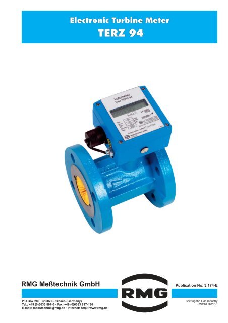
Electronic Turbine Meter<br />
<strong>TERZ</strong> <strong>94</strong><br />
RMG Meßtechnik GmbH<br />
Publication No. 3.174-E<br />
P.O.Box 280 · 35502 Butzbach (Germany)<br />
Tel.: +49 (0)6033 897-0 · Fax: +49 (0)6033 897-130<br />
E-mail: messtechnik@rmg.de · Internet: http://www.rmg.de<br />
Serving the Gas Industry<br />
- WORLDWIDE
1. Method of operation<br />
The <strong>TERZ</strong> <strong>94</strong> electronic turbine meter is a flow meter<br />
which directly measures the flow rate of gases at<br />
measurement conditions. The flow rate measured and<br />
the volume are displayed on an electronic totalizer.<br />
The operating principle of the meter is based on<br />
velocity measurement using a turbine wheel. The gas<br />
flow passes the ring-shaped inlet section of the flow<br />
straightener and reaches the coaxially mounted<br />
turbine wheel, whose speed is proportional to the<br />
mean velocity of the gas flow within the scope of the<br />
measuring range.<br />
The speed of the turbine wheel is recorded inductively<br />
using non-contact measurement by a pulse-wire<br />
sensor and a permanent magnet. Due to the fact that<br />
the signal frequency is directly picked up at the turbine<br />
wheel, the meter is also suitable for control<br />
applications.<br />
2.<br />
Construction<br />
The electronic turbine meters form a series of uniform<br />
construction. Each meter consists of four structural<br />
units (see drawing). An aerodynamic flow straightener<br />
fitted into the meter case constricts the effective cross<br />
section of the pipe to form a ring-shaped crosssectional<br />
area and substantially eliminates turbulence.<br />
This increases the velocity of the flowing gas. The<br />
shaft mounted with ball bearings carries the turbine<br />
wheel on the one side and a permanent magnet<br />
rotating before the sensor on the other. The duct of the<br />
sensor sleeve towards the unpressurized section of<br />
the electronic totalizer is sealed off by a pressure-tight<br />
O-ring. By means of the clamping screw, the electronic<br />
totalizer can be fixed in the most favourable position<br />
for taking readings.<br />
Socket<br />
Totalizer<br />
Earthing screw<br />
Sensor sleeve<br />
Clamping screw<br />
O-ring<br />
O-ring<br />
Sensor<br />
Flow straightener<br />
Permanent magnet<br />
Turbine wheel<br />
Ball bearing<br />
3. Types of gases<br />
The <strong>TERZ</strong> <strong>94</strong> standard design is suitable for all gases<br />
complying with DVGW Code of Practice G260. The<br />
materials used are appropriate for gases and fuel<br />
gases, such as natural gas, refinery gas, liquid gases<br />
and their mixtures, nitrogen, CO (dry), air and all<br />
2<br />
inert gases.<br />
For corrosive and chemical gases, there are special<br />
designs available with PTFE lining, special material,<br />
special lubrication, etc.
max<br />
min<br />
24 VDC<br />
MESSTECHNIK GMBH<br />
Germany<br />
Further data:<br />
press button<br />
Current output 4-20mA yes no<br />
IP65<br />
4. Characteristics<br />
· Electronic totalizers<br />
(Main totalizer, additional start-stop or resettable<br />
totalizer for external totalizer disablement in order to<br />
suppress the slow-down effect of the turbine wheel<br />
after the gas flow has stopped.)<br />
· 2 sensor inputs (option)<br />
with mutual monitoring<br />
· Battery mode (version without a current board)<br />
Service life of the battery is a minimum of 6 years.<br />
· 4-20 mA current output (transmitter)<br />
(only with the version with a current board)<br />
· Low-torque metering system with long-term<br />
stability<br />
(apart from the turbine wheel, there are no<br />
mechanically actuated parts)<br />
· LF and HF pulse outputs<br />
(The pulse value of the LF pulse output is userprogrammable.)<br />
· Intrinsically safe circuit, approved for zone 1<br />
· Degree of protection: IP 65<br />
· Flow display<br />
· Storage of maximum values (Qm)<br />
· Temperature ranges (standard)<br />
Fluid temperature range: -10°C to +50°C<br />
Ambient temperature range: -20°C to +60°C<br />
· Compact construction with a rotatable meter head<br />
· Option for use as a remote totalizer<br />
· Alarm output (option)<br />
5. Approvals<br />
II 2 G EEx ib[ia] II C T4 / T3<br />
as per certificate of conformity No.: TÜV 02 ATEX 1970<br />
DVGW product ID No.: CE-0085BN0292<br />
(Testing in accordance with the Directive for Pressure<br />
Equipment 97/23/EG)<br />
6. Electronic totalizer<br />
Possible connections of the electronic totalizer:<br />
HF pulse output<br />
(high frequency)<br />
direct signal frequency<br />
LF pulse output<br />
(low frequency)<br />
decade-scaled<br />
Switch input<br />
for stopping the totalizer<br />
Transistor, open collector Transistor, open collector Switching contact<br />
(potential-free)<br />
4-20 mA current output<br />
Version with a current board<br />
(option)<br />
U max = 28 V (Ex)<br />
U max = 28 V (Ex)<br />
Totalizer stop:<br />
30 V (non Ex)<br />
30 V (non Ex) closed contact<br />
U max = 28 V<br />
U min = 4.0 V<br />
U min = 4.0 V<br />
U min = 12 V<br />
I max = 30 mA<br />
I max = 30 mA<br />
I max = 23 mA<br />
T pulse =1ms<br />
T pulse = 125 or 250 ms<br />
I min = 3.5 mA<br />
f max = 250 Hz<br />
f max =4Hz<br />
For frequency values, see<br />
table below Overview section<br />
For possible setting values,<br />
see table below Overview<br />
section<br />
Current loop connection<br />
(4-20 mA, 2-wire technology)<br />
Error less than 1% of the final<br />
value.<br />
External power supply unit<br />
required.<br />
Connection of the current output (example for installation in areas subject to explosion hazards)<br />
Volumeter<br />
Type <strong>TERZ</strong> <strong>94</strong><br />
- 0085<br />
DN<br />
Q<br />
Q<br />
PS<br />
Ser.-No.<br />
Year<br />
m³/h<br />
m³/h<br />
bar<br />
4-20 mA current output (option)<br />
LF HF<br />
pulse outputs<br />
Current<br />
loop<br />
24VDC<br />
EEx i supply unit<br />
KFD2-STC3-Ex 1<br />
Current<br />
output<br />
4-20 mA<br />
The <strong>TERZ</strong> <strong>94</strong> version with a current board has a<br />
current-loop connection (4-20 mA, 2-wire technology).<br />
A power supply unit and, if appropriate, a 24 V power<br />
pack are required to power the device and output a<br />
current.<br />
In addition, a back-up battery can be provided as an<br />
emergency power supply.<br />
Hazardous area<br />
Safe area
7 . Overview<br />
Nominal size Measuring range Pulse value Pressure loss Lubrication<br />
Q min -Q max<br />
LF 1) HF 2) Dp<br />
mm in. m 3/h<br />
pulses/m 3 pulses/m 3 mbar permanently<br />
lubricated<br />
oil pump<br />
25<br />
40<br />
50<br />
1<br />
1½<br />
2<br />
2.5 -<br />
6-<br />
6-<br />
25<br />
70<br />
100<br />
10/100<br />
1/10/100<br />
1/10/100<br />
13450<br />
7800<br />
7800<br />
3<br />
4<br />
5<br />
•<br />
•<br />
•<br />
80<br />
100<br />
150<br />
200<br />
250<br />
300<br />
400<br />
500<br />
600<br />
3<br />
4<br />
6<br />
8<br />
10<br />
12<br />
16<br />
20<br />
24<br />
10 -<br />
25 -<br />
40 -<br />
100 -<br />
160 -<br />
250 -<br />
400 -<br />
650 -<br />
1000 -<br />
250<br />
400<br />
1000<br />
1600<br />
2500<br />
4000<br />
6500<br />
10000<br />
16000<br />
0.1/ 1/10<br />
0.1/ 1/10<br />
0.1/ 1/10<br />
0.1/ 1<br />
0.1/ 1<br />
0.1/ 1<br />
0.1/1<br />
0.1/1<br />
0.01/ 0.1<br />
2375<br />
1060<br />
330<br />
135<br />
75<br />
48<br />
24<br />
12<br />
6<br />
6<br />
4<br />
6<br />
3<br />
3<br />
4<br />
3<br />
4<br />
4<br />
•<br />
•<br />
•<br />
•<br />
•<br />
•<br />
•<br />
•<br />
•<br />
3<br />
4<br />
6<br />
8<br />
10<br />
12<br />
16<br />
20<br />
24<br />
25 -<br />
40 -<br />
100 -<br />
160 -<br />
250 -<br />
400 -<br />
650 -<br />
1000 -<br />
1600 -<br />
400<br />
650<br />
1600<br />
2500<br />
4000<br />
6500<br />
10000<br />
16000<br />
25000<br />
0.1/ 1<br />
0.1/ 1/10<br />
0.1/ 1<br />
0.1/ 1<br />
0.1/ 1<br />
0.1/ 1<br />
0.1/1<br />
0.01/ 0.1<br />
0.01/ 0.1<br />
1250<br />
600<br />
190<br />
80<br />
44<br />
28<br />
14<br />
7<br />
4<br />
14<br />
10<br />
12<br />
8<br />
7<br />
9<br />
8<br />
9<br />
9<br />
•<br />
•<br />
•<br />
•<br />
•<br />
•<br />
•<br />
•<br />
•<br />
1) Standard values (set in the factory) are shown in bold type.<br />
2) Approximate value; the exact value is determined during calibration.<br />
8. Pressure loss<br />
The pressure loss Dp stated in the table applies to natural<br />
gas at Qmax<br />
and 1 bar(a). From this, the pressure loss at<br />
measurement conditions can be calculated in accordance<br />
with the formula below.<br />
Pressure loss as per the formula<br />
Dp<br />
m = Pressure loss at measurement conditions<br />
(p m, Q m) in mbar<br />
Dp = Pressure loss at Qmax<br />
and natural gas at 1 bar<br />
in mbar (see table)<br />
rn<br />
= Standard density of the process gas (kg/m 3)<br />
p m = Pressure at measurement conditions<br />
in bar (absolute)<br />
Q m = Flow rate at measurement conditions (m 3/h)<br />
Q = Maximum flow rate<br />
max<br />
2<br />
rn Qm<br />
• • m •<br />
( Qmax )<br />
Dp m = Dp p<br />
0.83<br />
Example: Air, nominal meter size DN 100, measuring<br />
range 20 - 400 m 3/h, p m = 1.1 bar(abs),<br />
rn<br />
= 1.29 kg/m 3, Q m = 250 m 3/h<br />
take from the table: Dp = 4 mbar<br />
Hence:<br />
2<br />
1.29 250<br />
Dp m = 4 • • 1.1 • = 2.7 mbar<br />
0.83 ( 400 )<br />
9. Measuring accuracy<br />
Measuring error: Qmin to 0.2 · Qmax 0.2 · Qmax to Qmax<br />
DN 25: ± 3% ± 2%<br />
DN 40, DN 50: ± 3% ± 1.5%<br />
DN 80: ± 3% ± 1%<br />
³ DN 100: ± 2% ± 1%<br />
Reproducibility: £ ± 0.5%<br />
10. Maintenance<br />
All turbine meters up to and including the nominal size of<br />
DN 150 are fitted with permanently lubricated bearings<br />
and require no maintenance. From the nominal size of<br />
DN 200, the meters are fitted with a lubricator.<br />
Lubrication has to be performed in compliance with the<br />
operating instructions (see also lubrication instruction<br />
plate on the meter).
11. Types of construction and dimensions<br />
A<br />
A<br />
A<br />
A<br />
B<br />
C<br />
B<br />
C<br />
B<br />
C<br />
B<br />
C<br />
L<br />
L<br />
L<br />
L<br />
Flanged-end design ( F)<br />
Sandwich design ( S)<br />
Monoflange design ( M)<br />
Threaded-end design ( G)<br />
(Adaptor-flange mounting)<br />
(only aluminium cases)<br />
Weights and measures<br />
Pressure rating<br />
Case Nominal L A B C Weight PN 10 PN 25 PN 40 ANSI 300 PN 64<br />
design size mm mm mm mm kg1)<br />
PN 16 ANSI 150 PN 100<br />
mm ANSI 600<br />
G<br />
252)<br />
185 80 145 195 4 Alu<br />
Threads 403)<br />
140 80 145 195 4 Alu<br />
50 150 60 180 265 10 • • • •<br />
80 120 35 215 315 14 • • •<br />
100 150 50 225 345 25 • • •<br />
150 175 70 255 410 40 • • •<br />
200 200 70 280 470 60 • • •<br />
F<br />
250 300 135 320 540 70 • •<br />
300 95 325 580 100 • •<br />
300<br />
450 200 325 610 200<br />
• • •<br />
Flanges 400 145 335 650 180 • •<br />
400<br />
600 345 335 680 400<br />
• • •<br />
500<br />
400 110 385 760 300 • •<br />
750 260 385 810 650<br />
• • •<br />
600<br />
600 130 440 870 400 • •<br />
900 280 440 920 850<br />
•<br />
50 80 60 175 255 15<br />
•<br />
80 120 35 200 300 35<br />
• •<br />
M 100 150 50 225 355 50<br />
• •<br />
Mono- 150 175 70 270 445 100<br />
• •<br />
flanges 200 200 70 305 510 130<br />
• •<br />
250 250 85 345 590 200<br />
• • •<br />
50 80 30 145 195 124)<br />
Alu •<br />
80 120 30 200 280 20 • •<br />
100 150 50 220 330 30 • •<br />
S<br />
150 175 70 250 400 50 • •<br />
Sandwich 200 200 70 280 450 70 • •<br />
250 250 85 315 530 110 • •<br />
1) The weights are approximate values. Devices with a lower pressure rating can have a lower weight.<br />
2) External thread R 1½"; with coupling kit: internal thread Rp1 ISO 7-1, overall length 243 mm<br />
3) External thread R 2¼"; with coupling kit: internal thread Rp1½ ISO 7-1, overall length 206 mm<br />
4) 4 kg for PN 10 and PN 16 (aluminium case)<br />
Special designs on request.
DN<br />
Q max<br />
Q min<br />
PS<br />
Ser.-No.<br />
Year<br />
24 VDC<br />
m³/h<br />
m³/h<br />
bar<br />
MESSTECHNIK GMBH<br />
Germany<br />
Further data:<br />
press button<br />
Current output 4-20mA yes no<br />
- 0085<br />
IP65<br />
Electronic Turbine Meter<br />
<strong>TERZ</strong> <strong>94</strong><br />
12. Options for installing the electronic totalizer<br />
By installing the electronic totalizer in different ways,<br />
optimum readings can be taken in any position. If no<br />
special type of installation is specified, the totalizer is to<br />
be installed in accordance with the figure below.<br />
00064419<br />
F 1.4<br />
Standard design<br />
Volumeter<br />
Type <strong>TERZ</strong> <strong>94</strong><br />
Totalizer<br />
00064419<br />
F 1.4<br />
00064419<br />
F 1.4<br />
LIYCY cable<br />
2x0.75 blue<br />
Max. cable length: 50 m<br />
Options for installing the totalizer<br />
Remote totalizer<br />
Measuring<br />
element<br />
13. Device variants<br />
Our product range also includes the following device<br />
types which are based on the electronics of the <strong>TERZ</strong> <strong>94</strong>:<br />
TRZ03-TE/TEL electronic turbine meter<br />
1 or 2 channels, measuring element as with the <strong>TERZ</strong> <strong>94</strong>,<br />
but incorporated into the housing of the TRZ 03 or<br />
TRZ 03-L. The 2-channel version has been approved for<br />
custody transfer measurement (PTB 7.211/02.13).<br />
EC 21 temperature corrector<br />
1 or 2 channels, directly installed on a turbine meter or<br />
volumeter with an electronic measuring element<br />
(Wiegand sensors) or 1-channel version installed together<br />
with a (separate) mechanical totalizer (volume pulses<br />
from reed contact). With a Vm totalizer and a corrector<br />
function with measured temperature values and a fixed<br />
pressure value.<br />
incorporated into the housing.<br />
All variants receiving signals from Wiegand sensors, i.e.<br />
all variants which are directly installed on the meter, have<br />
LF and HF pulse outputs and are available as devices<br />
with a current output.<br />
7.745<br />
04.12<br />
EC 21 temperature corrector<br />
(or totalizer of the TRZ 03-TE/TEL)<br />
EC 24 volume corrector<br />
1 or 2 channels as with the EC 21, directly installed on a<br />
turbine meter or volumeter with electronic measuring<br />
element (Wiegand sensors) or 1-channel version installed<br />
together with a (separate) mechanical totalizer (volume<br />
pulses from reed contact). The EC 24 includes a Vm<br />
totalizer and a corrector function with measured pressure<br />
and temperature values. The pressure transmitter is<br />
7.741<br />
03.53<br />
EC 24 volume corrector<br />
RMG Meßtechnik GmbH<br />
Publication No. 3.174-E<br />
P.O.Box 280 · 35502 Butzbach (Germany)<br />
Tel.: +49 (0)6033 897-0 · Fax: +49 (0)6033 897-130<br />
E-mail: messtechnik@rmg.de · Internet: http://www.rmg.de<br />
Status: 05/2005<br />
Subject to technical modification<br />
without prior notice.