PCIe Devices - PLX Technology
PCIe Devices - PLX Technology
PCIe Devices - PLX Technology

Create successful ePaper yourself
Turn your PDF publications into a flip-book with our unique Google optimized e-Paper software.
Presents<br />
PCI Express Overview<br />
By Pamela Frinzi<br />
Copyright by Dashcourses Inc, 2009
Introduction<br />
n<br />
n<br />
n<br />
Objectives<br />
Specifications Covered<br />
Presentation Layout<br />
Copyright by Dashcourses, Inc. 2009<br />
Intro-2
What This Presentation Is About<br />
n<br />
The basic <strong>PCIe</strong> architectural components and their<br />
interactions<br />
l<br />
<strong>PCIe</strong> high speed serial interconnect, usage, and operations<br />
– <strong>PCIe</strong> terminology<br />
• Fabric, ports, links, paths, packets<br />
– The <strong>PCIe</strong> protocol stack<br />
• Transaction Layer, Data Link Layer, and Physical Layer requirements,<br />
operations, and header formats<br />
– Understand the concept of ‘virtual channels’ and the <strong>PCIe</strong> term<br />
‘differentiated services’<br />
• Bridging, posting, and arbitration<br />
• Effects on latency and ‘differentiated services’<br />
– <strong>PCIe</strong> configuration requirements<br />
• <strong>PCIe</strong> required and optional register sets<br />
Copyright by Dashcourses, Inc. 2009<br />
Intro-3
What This Presentation Is About (continued)<br />
n<br />
<strong>PCIe</strong> is an extension of the basic PCI (Peripheral<br />
Component Interface) specification<br />
l<br />
l<br />
A brief review of the PCI architecture will be provided<br />
– System terminology, operation, and usage<br />
– Basic PCI and PCI-X protocol, bus operations, bus arbitration, and<br />
commands<br />
– Bridging in PCI<br />
– PCI device configuration space and configuration space access<br />
PCI and PCI-X will be discussed as it relates to <strong>PCIe</strong> and<br />
compatibility requirements<br />
Copyright by Dashcourses, Inc. 2009<br />
Intro-4
Specifications<br />
n<br />
The current <strong>PCIe</strong> specifications as published by the<br />
PCI Special Interest group or PCI Sig are<br />
l <strong>PCIe</strong> 2.0 (December 20, 2006)<br />
– Supporting specifications<br />
• PCI Express Card Electromechanical Specification, Revision 1.12.0<br />
• PCI Express to PCI/PCI-X Bridge Specification, Revision 1.0<br />
• PCI Express Mini Card Electromechanical Specification, Revision 1.1<br />
• PCI Local Bus Specification, Revision 3.0<br />
• PCI-X Addendum to the PCI Local Bus Specification, Revision 2.0<br />
• PCI Hot-Plug Specification, Revision 1.1<br />
• PCI Standard Hot-Plug Controller and Subsystem Specification,<br />
Revision 1.0<br />
• PCI-to-PCI Bridge Architecture Specification, Revision 1.2<br />
• PCI Bus Power Management Interface Specification, Revision 1.2<br />
• Advanced Configuration and Power Interface Specification, Revision<br />
2.03.0b<br />
• Guidelines for 64-bit Global Identifier (EUI-64) Registration Authority<br />
Copyright by Dashcourses, Inc. 2009<br />
Intro-5
Standards Body<br />
n<br />
Pioneered by Intel, the PCI specification has<br />
become a ‘defacto’ industry standard<br />
l<br />
Controlled by the PCI Special Interest Group or PCI SIG<br />
PCI special interest group<br />
2575 N.E. Kathryn #17<br />
Hillsboro, Oregon 97124<br />
800-433-5177 (USA)<br />
503-693-6232 (international)<br />
503-693-8344 (fax)<br />
pcisig@pcIsig.com<br />
Http://www.pcisig.com<br />
Copyright by Dashcourses, Inc. 2009<br />
Intro-6
Presentation Layout<br />
Section 1 - PCI Evolution and Architectural Overview<br />
Section 2 - <strong>PCIe</strong> Transaction Layer<br />
Section 3 - <strong>PCIe</strong> Data Link Layer<br />
Section 4 - <strong>PCIe</strong> Physical Layer<br />
Copyright by Dashcourses, Inc. 2009<br />
Intro-7
Section 1<br />
PCI Express Evolution and Architectural Overview<br />
Copyright by Dashcourses Inc, 2009<br />
Copyright by Dashcourses, Inc. 2009
PCI Specification History<br />
n<br />
n<br />
n<br />
PCI Local Bus Specification<br />
l Version 1.0 released by Intel TM June 22, 1992<br />
l Version 2.0 released April of 1993<br />
– Version 2.1 released 1st quarter 1995<br />
– Version 2.2 released February of 1999<br />
– Version 2.3 released March 29, 2002<br />
l Version 3.0 released February 3, 2004<br />
<strong>PCIe</strong> is an extension of the PCI Local Bus Specification<br />
l Version 1.0 released July 22, 2002<br />
– Version 1.0a released April 15, 2003<br />
l Version 1.1 released March 28, 2005<br />
l Version 2.0 released December 20, 2007<br />
PCI is not a ‘PC’ standard 1 , but is a computing I/O<br />
specification<br />
1 PCI is not a standards body specification, it is a vendors consortium specification.<br />
Copyright by Dashcourses, Inc. 2009<br />
1-9
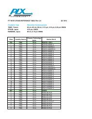
PCI I/O Bandwidth Evolution<br />
10,000<br />
2.5 and 5.0 GT/s<br />
Packetized<br />
<strong>PCIe</strong><br />
Bandwidth (MB/s)<br />
1,000<br />
100<br />
10<br />
12 MHz<br />
32-bit<br />
EISA<br />
33 MHz<br />
32/64-bit<br />
PCI<br />
66 MHz<br />
32/64-bit<br />
PCI<br />
66/100/133/266/512 MHz<br />
32/64-bit<br />
PCI-X<br />
1<br />
ISA<br />
6 MHz<br />
16-bit<br />
1986 1988 1990 1992 1994 1996 1998 2000 2002 2004<br />
Copyright by Dashcourses, Inc. 2009<br />
1-10
<strong>PCIe</strong> Compatibility and New Features<br />
n<br />
<strong>PCIe</strong> is backwards compatible at the binary level<br />
with PCI and PCI-X<br />
l<br />
Configuration space, commands, and device access are<br />
indistinguishable<br />
– <strong>PCIe</strong> adds a mandatory new register set and several optional<br />
register sets<br />
• Provides foundation for most of <strong>PCIe</strong> new features<br />
n<br />
<strong>PCIe</strong> hardware interconnect is entirely new<br />
l<br />
l<br />
High speed serial interconnect<br />
– Can be striped providing speed enhancements (scaling)<br />
• Signaling enhancements are planned<br />
Introduces a three layer protocol stack<br />
– Provides end-to-end, point-to-point, and electrical service<br />
• Protocol stack mostly built in hardware and silicon<br />
Copyright by Dashcourses, Inc. 2009<br />
1-11
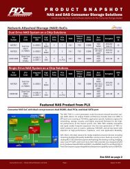
<strong>PCIe</strong> Interconnects – Chip-to-Chip<br />
CPU<br />
CPU<br />
<strong>PCIe</strong> Serial Links<br />
<strong>PCIe</strong> Serial Links<br />
DVD<br />
MONITOR<br />
AGP<br />
Chip<br />
Set<br />
System<br />
Memory<br />
Camera<br />
Copyright by Dashcourses, Inc. 2009<br />
1-12
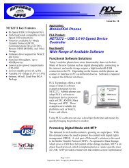
<strong>PCIe</strong> Interconnect – Chip-to-Board<br />
CPU<br />
CPU<br />
<strong>PCIe</strong> Serial Links<br />
<strong>PCIe</strong> Serial Links<br />
DVD<br />
MONITOR<br />
AGP<br />
Chip<br />
Set<br />
System<br />
Memory<br />
Camera<br />
<strong>PCIe</strong> Serial<br />
Links<br />
PCI Bridge 1<br />
PCI Embedded<br />
<strong>PCIe</strong><br />
NIC<br />
<strong>Devices</strong> 1 Connectors<br />
PCI Bus<br />
PCI Connectors 1<br />
1<br />
Referred to as ‘Legacy <strong>Devices</strong>’<br />
Copyright by Dashcourses, Inc. 2009<br />
1-13
<strong>PCIe</strong> Interconnect – External Connections<br />
<strong>PCIe</strong> Serial Links<br />
(specification released January 2007)<br />
<strong>PCIe</strong> Device<br />
<strong>PCIe</strong> Switch<br />
<strong>PCIe</strong> Device <strong>PCIe</strong> Device <strong>PCIe</strong> Device<br />
Copyright by Dashcourses, Inc. 2009<br />
1-14
<strong>PCIe</strong> Design Possibilities<br />
Embedded <strong>Devices</strong><br />
CPU<br />
CPU<br />
Video<br />
Graphics<br />
Root Complex<br />
Memory<br />
Switch<br />
Switch<br />
Sound System<br />
Synthesizer<br />
SCSI<br />
Controller<br />
Ethernet<br />
Controller<br />
Bridge<br />
USB<br />
Controller<br />
Multiple 192 Kbps Channels<br />
<strong>PCIe</strong> Add-In Connectors<br />
PCI/PCI-X Add-In Connectors<br />
Copyright by Dashcourses, Inc. 2009<br />
1-15
<strong>PCIe</strong> Protocol Stack Logical Layering<br />
Application and<br />
System Software<br />
Application and<br />
System Software<br />
Transaction Layer<br />
Transaction Layer<br />
Data Link Layer<br />
Physical Layer<br />
Logical Sub-block<br />
<strong>PCIe</strong><br />
Specification<br />
Data Link Layer<br />
Physical Layer<br />
Logical Sub-block<br />
Physical Sub-block<br />
Physical Sub-block<br />
TX<br />
RX<br />
Packet<br />
TX<br />
RX<br />
Packet<br />
Copyright by Dashcourses, Inc. 2009<br />
1-16
Compatibility with Existing PCI Specification<br />
n<br />
n<br />
Ability to enumerate and configure <strong>PCIe</strong> hardware<br />
using PCI system configuration software (OS) with<br />
no modifications<br />
l<br />
l<br />
l<br />
PCI devices (across a <strong>PCIe</strong>-PCI bridge) must be accessible by<br />
existing OSs and device drivers<br />
<strong>PCIe</strong> add-in card must be accessible to existing OSs and<br />
capable of being configured<br />
Compatibility includes<br />
– Boot over existing OS<br />
– Support existing I/O device drivers (at binary level)<br />
– Support existing applications<br />
New software required to configure/enable new<br />
<strong>PCIe</strong> functionality by adopting the PCI<br />
configuration paradigm<br />
Copyright by Dashcourses, Inc. 2009<br />
1-17
Low Latency and High Bandwidth<br />
n<br />
n<br />
n<br />
Low-overhead<br />
l<br />
Maximize application payload bandwidth, and link efficiency<br />
– Application and/or local OS determines required mix<br />
Low-latency communications<br />
l<br />
Maximum allowable delay or processing time through link<br />
devices within the fabric<br />
– Can calculate (deterministic) delay on end-to-end basis within<br />
the fabric<br />
High speed serial interconnect<br />
l<br />
l<br />
l<br />
2.5 and 5.0 Gbps wire speed – called GT/s or giga transfers<br />
per second<br />
– Can be aggregated<br />
Low pin count per device and connector interface<br />
Longer connection runs<br />
– Traces on PCBs or cables external<br />
Copyright by Dashcourses, Inc. 2009<br />
1-18
New Features<br />
n<br />
Improved data integrity<br />
l<br />
l<br />
Link-level data integrity for all types of transactions and<br />
packets<br />
– Sequence Number and Link CRC (LCRC) within data link layer<br />
header provided<br />
End-to-end CRC (ECRC) data integrity for high availability<br />
solutions<br />
n<br />
Error handling<br />
l<br />
l<br />
Legacy PCI-level error handling<br />
Advanced error reporting and handling for improved fault<br />
isolation and recovery<br />
Copyright by Dashcourses, Inc. 2009<br />
1-19
New Features (continued)<br />
n<br />
Ability to differentiate services (Quality of<br />
Service or QoS)<br />
l<br />
l<br />
l<br />
l<br />
Configurable arbitration policy within every component<br />
End-to-end QoS tag with each packet<br />
Support for isochronous traffic<br />
Packet prioritization<br />
n<br />
Hot Plug and Hot Swap Support<br />
l<br />
l<br />
Support for legacy PCI<br />
Software model for all form factors<br />
Copyright by Dashcourses, Inc. 2009<br />
1-20
Scalable Topologies<br />
n<br />
Hierarchies using PCI bridge and switch<br />
configurations<br />
l<br />
l<br />
<strong>PCIe</strong>-PCI bridge<br />
– Box-to-box connection to legacy PCI based machines<br />
– <strong>PCIe</strong> to PCI or PCI-X bus bridging<br />
Network type capability with point-to-point serial<br />
connections by way of <strong>PCIe</strong> switches<br />
n<br />
Ability to aggregate ‘Lanes’ to increase<br />
bandwidth through core hierarchical fabric<br />
components<br />
l<br />
Greater bandwidth by ‘striping’ <strong>PCIe</strong> Links<br />
Copyright by Dashcourses, Inc. 2009<br />
1-21
PCI and PCI-X Commands<br />
n<br />
100% binary compatibility with existing PCI/PCI-X<br />
C/BE[0:3]#<br />
0000b<br />
0001b<br />
0010b<br />
0011b<br />
0100b<br />
0101b<br />
0110b<br />
0111b<br />
1000b<br />
1001b<br />
1010b<br />
1011b<br />
1100b<br />
1101b<br />
1110b<br />
1111b<br />
PCI<br />
Command<br />
Interrupt Acknowledge<br />
Special Cycle<br />
I/O Read<br />
I/O Write<br />
Reserved<br />
Reserved<br />
Memory Read<br />
Memory Write<br />
Reserved<br />
Reserved<br />
Configuration Read<br />
Configuration Write<br />
Memory Read Multiple<br />
Dual Address Cycle<br />
Memory Read Line<br />
Memory Write and<br />
Invalidate<br />
PCI-X<br />
Command<br />
Interrupt Acknowledge<br />
Special Cycle<br />
I/O Read<br />
I/O Write<br />
Reserved<br />
Device ID Message 1<br />
Memory Read DWord<br />
Memory Write<br />
Alias to Memory Read Block<br />
Alias to Memory Write Block<br />
Configuration Read<br />
Configuration Write<br />
Split Completion 1<br />
Dual Address Cycle<br />
Memory Read Block 1<br />
Memory Write Block 1<br />
Length<br />
DWord<br />
DWord<br />
DWord<br />
DWord<br />
N/A<br />
Burst<br />
DWord<br />
Burst<br />
Burst<br />
Burst<br />
DWord<br />
DWord<br />
Burst<br />
N/A<br />
Burst<br />
Burst<br />
1 Commands added in PCI-X<br />
Copyright by Dashcourses, Inc. 2009<br />
1-22
PCI and PCI-X Architecture and Command Execution<br />
Host System<br />
PCI Device<br />
Device Function<br />
Configuration R/W<br />
Configuration R/W<br />
Memory R/W<br />
I/O R/W<br />
Requestor<br />
(Completer)<br />
Completer<br />
(Requestor)<br />
Memory R/W<br />
I/O R/W<br />
Messages<br />
Messages<br />
Host-to-PCI<br />
Bus Bridge<br />
PCI Bus<br />
Device Interface<br />
PCI Bus 0<br />
Copyright by Dashcourses, Inc. 2009<br />
1-23
<strong>PCIe</strong> Commands<br />
TLP Type<br />
Fmt<br />
[1:0]<br />
Type<br />
[4:0] Description<br />
MRd<br />
00 and 01<br />
0 0000<br />
Memory Read Request<br />
MRdLk<br />
00 and 01<br />
0 0001<br />
Memory Read Request Locked<br />
MWr<br />
10 and 11<br />
0 0000<br />
Memory Write Request<br />
IORd<br />
00<br />
0 0010<br />
I/O Read Request<br />
IOWr<br />
CfgRd0<br />
CfgWr0<br />
CfgRd1<br />
CfgWr1<br />
Msg<br />
MsgD<br />
10 0 0010 I/O Write Request<br />
00 0 0100 Configuration Read Type 0<br />
10 0 0100 Configuration Write Type 0<br />
00 0 0101 Configuration Read Type 1<br />
10 0 0101 Configuration Write Type 1<br />
01 1 0r 2<br />
r 1<br />
r 0<br />
Message Request, sub-field r[2:0]<br />
Specifies the Message routing mechanism<br />
11 1 0r 2<br />
r 1<br />
r 0<br />
Message Request with data payload, sub-field r[2:0]<br />
Specifies Message routing mechanism<br />
Copyright by Dashcourses, Inc. 2009<br />
1-24
<strong>PCIe</strong> Command Execution<br />
Host System<br />
<strong>PCIe</strong> Device<br />
Device Function<br />
Configuration R/W<br />
Configuration R/W<br />
Memory R/W<br />
Requestor<br />
Completer<br />
Memory R/W<br />
I/O R/W<br />
I/O R/W<br />
Messages<br />
Messages<br />
Root Complex<br />
Transaction Layer<br />
Transaction Layer<br />
Data Link Layer<br />
Data Link Layer<br />
Physical Layer<br />
Physical Layer<br />
<strong>PCIe</strong> Link<br />
<strong>PCIe</strong> Packet<br />
<strong>PCIe</strong> Transaction<br />
Copyright by Dashcourses, Inc. 2009<br />
1-25
<strong>PCIe</strong> Link is a Point-to-Point Connection<br />
n<br />
<strong>PCIe</strong> Link connection is a dual-simplex channel<br />
between two components<br />
l<br />
l<br />
Components can be endpoints, bridges, or switches<br />
An <strong>PCIe</strong> Link consists of two, low-voltage, differentially<br />
driven signal pairs<br />
– One transmit pair (simplex) and one receive pair (simplex)<br />
• Data encoded in formatted packets<br />
Serial Packets<br />
Device<br />
A<br />
Device<br />
B<br />
Serial Packets<br />
<strong>PCIe</strong> Link<br />
Packets<br />
Copyright by Dashcourses, Inc. 2009<br />
1-26
<strong>PCIe</strong> Transactions and Packets<br />
n<br />
<strong>PCIe</strong> transactions consist of one or more serial<br />
packets<br />
l<br />
Packets can vary in size depending on the command<br />
– Information about the transaction is defined in the fields in the<br />
<strong>PCIe</strong> packet headers<br />
• Packets may or may not have a payload and CRC(s)<br />
– Two basic packet types (Transaction Layer packets or TLPs<br />
and Data Link Layer packets or DLLPs )<br />
Physical/Data Link<br />
Header<br />
Transaction Layer<br />
Header<br />
Payload ECRC LCRC<br />
11010110100100010101101001011010001011100010111010001011010010111101011101111101101001011<br />
Device<br />
A<br />
<strong>PCIe</strong> Link<br />
Serial Packets<br />
Serial Packets<br />
Device<br />
B<br />
Copyright by Dashcourses, Inc. 2009<br />
1-27
<strong>PCIe</strong> Packet Delineation or Framing<br />
n<br />
<strong>PCIe</strong> packets are detected or delineated at<br />
receiver by matching predefined symbols<br />
l<br />
l<br />
l<br />
Referred to as framing symbols<br />
Detection of predefined symbol sets determines where the<br />
first bit of the packet is and how the packet will be decoded<br />
– Received as a TLP or DLLP<br />
Beginning and ending packet symbols are required for all<br />
validated packets<br />
Physical/Data Link<br />
Header<br />
Transaction Layer<br />
Header<br />
Payload ECRC LCRC<br />
11010110100100010101101001011010001011100010111010001011010010111101011101000101111001010000001011010110101<br />
Device<br />
A<br />
<strong>PCIe</strong> Link<br />
Serial Packets<br />
Serial Packets<br />
Device<br />
B<br />
Packet Framing Symbols<br />
Copyright by Dashcourses, Inc. 2009<br />
1-28
PCI <strong>Devices</strong><br />
n<br />
n<br />
n<br />
PCI is based on a defined bus structure<br />
One or more PCI compliant devices attached to<br />
the PCI bus<br />
l<br />
Each PCI device may contain up to eight PCI functions<br />
– PCI function - a logical device<br />
• For example a sound card, a video card, or an IDE controller<br />
– <strong>Devices</strong> control 1-8 logical functions<br />
<strong>Devices</strong> may be a master or a target<br />
l<br />
l<br />
l<br />
Masters may initiate a bus transaction<br />
– Require a request/grant (REQ#/GNT#) pair wired to an arbiter<br />
for each master on the bus<br />
Targets may not initiate a bus transaction<br />
– Exception is a PCI-X target completing a split transaction<br />
response<br />
<strong>Devices</strong> attach to PCI busses by way of bridges<br />
Copyright by Dashcourses, Inc. 2009<br />
1-29
PCI/PCI-X Device/Function<br />
PCI Single Function Device<br />
PCI Bus<br />
PCI Bus and<br />
Control Signals<br />
UART<br />
(Function)<br />
I/O<br />
PCI Multiple Function Device<br />
PCI Bus<br />
PCI Bus and<br />
Control Signals<br />
FDDI<br />
(Function)<br />
SCSI<br />
(Function)<br />
IDE Bus<br />
SCSI Bus<br />
Copyright by Dashcourses, Inc. 2009<br />
1-30
PCI Topology with Multiple Host/PCI Bus Bridge<br />
Processor Processor Processor<br />
Bus=0<br />
Subor=2<br />
Host/PCI<br />
Bridge 1<br />
Main<br />
Memory<br />
Host/PCI-X<br />
Bridge<br />
Bus=3<br />
Subor=4<br />
PCI Bus 0<br />
PCI/PCI<br />
Bridge<br />
Pri=0<br />
Sec=1<br />
Subor=2<br />
Pri=3<br />
Sec=4<br />
Subor=4<br />
PCI-X/PCI-X<br />
Bridge<br />
PCI Bus 3<br />
Pri=1<br />
Sec=2<br />
Subor=2<br />
PCI/PCI<br />
Bridge<br />
PCI Bus 1<br />
PCI Bus 4<br />
PCI Bus 2<br />
1 Only 1 Host/PCI bus numbered ‘0’. Initial<br />
starting point for bus enumeration.<br />
Copyright by Dashcourses, Inc. 2009<br />
1-31
<strong>PCIe</strong> <strong>Devices</strong><br />
n<br />
Same definition as for PCI and PCI-X devices<br />
with the following additions/modifications<br />
l<br />
l<br />
<strong>PCIe</strong> devices must be compliant with ‘legacy’ operating<br />
system plug-and-play software utilities<br />
– Means PCI enumeration, configuration, device driver,<br />
application, and, if applicable, interrupt utilities<br />
– <strong>PCIe</strong> devices (accept the Root Complex) must implement PCI<br />
required and optional configuration space<br />
• May optionally implement <strong>PCIe</strong> optional configuration space<br />
Connections between <strong>PCIe</strong> compliant devices is now over a<br />
serial link<br />
– Communications over the link is controlled by an <strong>PCIe</strong> three<br />
layer protocol stack<br />
Copyright by Dashcourses, Inc. 2009<br />
1-32
<strong>PCIe</strong> Device/Function<br />
<strong>PCIe</strong> Single Function Device<br />
<strong>PCIe</strong><br />
Link<br />
<strong>PCIe</strong><br />
Protocol Stack<br />
1G NIC<br />
(Function)<br />
I/O<br />
<strong>PCIe</strong> Multiple Function Device<br />
<strong>PCIe</strong><br />
Link<br />
<strong>PCIe</strong><br />
Protocol Stack<br />
IDE<br />
(Function)<br />
SCSI<br />
(Function)<br />
I/O<br />
SCSI Bus<br />
Copyright by Dashcourses, Inc. 2009<br />
1-33
<strong>PCIe</strong> Topology Originates from a Root Complex<br />
<strong>PCIe</strong> Root Complex<br />
<strong>PCIe</strong> Switch<br />
<strong>PCIe</strong> Switch<br />
<strong>PCIe</strong> Device <strong>PCIe</strong> Device <strong>PCIe</strong> Switch<br />
<strong>PCIe</strong> Device<br />
<strong>PCIe</strong> Device<br />
<strong>PCIe</strong> Device<br />
<strong>PCIe</strong> Device<br />
n<br />
Root Complex defines the origin of the root hub<br />
l All interconnects are hierarchical, point-to-point connections<br />
l<br />
All devices in the hierarchy constitute the <strong>PCIe</strong> ‘fabric’<br />
Copyright by Dashcourses, Inc. 2009<br />
1-34
<strong>PCIe</strong> System Fabric<br />
<strong>PCIe</strong> Root Complex<br />
<strong>PCIe</strong> Switch<br />
<strong>PCIe</strong> Switch<br />
<strong>PCIe</strong> Device <strong>PCIe</strong> Device <strong>PCIe</strong> Switch<br />
<strong>PCIe</strong> Device<br />
<strong>PCIe</strong> Device<br />
<strong>PCIe</strong> Device<br />
<strong>PCIe</strong> Device<br />
n<br />
The <strong>PCIe</strong> specification defines the rules, behaviors,<br />
requirements, and options for all devices within the fabric<br />
Copyright by Dashcourses, Inc. 2009<br />
1-35
<strong>PCIe</strong> Port Fabric<br />
<strong>PCIe</strong> Root Complex<br />
<strong>PCIe</strong> Switch<br />
<strong>PCIe</strong> Switch<br />
<strong>PCIe</strong> Device <strong>PCIe</strong> Device <strong>PCIe</strong> Switch<br />
<strong>PCIe</strong> Device<br />
<strong>PCIe</strong> Device<br />
<strong>PCIe</strong> Device<br />
<strong>PCIe</strong> Device<br />
n<br />
Each Root Port in the Root Complex defines its own fabric<br />
hierarchy<br />
Copyright by Dashcourses, Inc. 2009<br />
1-36
PCI/PCI-X/<strong>PCIe</strong> Bridges<br />
n<br />
Bridges are the mechanism that PCI devices use<br />
communicate to the host system resources, to<br />
other PCI devices, and to other PCI busses in the<br />
system<br />
n<br />
Several bridge types have been defined<br />
l<br />
l<br />
Host/PCI and host/PCI-X bridges<br />
– If multiple host bridges in system, one must be hardwired to<br />
indicate access to PCI bus 0<br />
– PCI/PCI (P-P bridge), PCI-X/PCI-X, and PCI/PCI-X bridges are<br />
defined<br />
The <strong>PCIe</strong> root complex is the equivalent to the PCI host-to-<br />
PCI bus bridge, only it implements the <strong>PCIe</strong> added<br />
functions, the <strong>PCIe</strong> protocol stack, and the <strong>PCIe</strong> serial link<br />
– <strong>PCIe</strong> switches are defined in terms of P-P bridges<br />
Copyright by Dashcourses, Inc. 2009<br />
1-37
<strong>PCIe</strong> and Bridges<br />
<strong>PCIe</strong> Root Complex<br />
<strong>PCIe</strong> Switch<br />
<strong>PCIe</strong> Switch<br />
<strong>PCIe</strong> Device <strong>PCIe</strong> Device <strong>PCIe</strong> Switch<br />
<strong>PCIe</strong> Device<br />
<strong>PCIe</strong> Device<br />
<strong>PCIe</strong> Device<br />
<strong>PCIe</strong> Device<br />
n<br />
A root complex and <strong>PCIe</strong> switches are P-P bridge structures<br />
l Every port connection from a switch or root complex logically<br />
operates as a P-P bridge<br />
Copyright by Dashcourses, Inc. 2009<br />
1-38
PCI/PCI-X Arbitration Example<br />
n<br />
n<br />
Four PCI devices are plugged into a PCI bus<br />
l<br />
l<br />
<strong>Devices</strong> A and B are grouped as high priority masters<br />
<strong>Devices</strong> X and Y are low priority masters<br />
If all masters make requests at same time, the<br />
sequence in which grants are made may be as<br />
follows<br />
Device Execution Priority<br />
Arbiter<br />
l A - first<br />
l B - second<br />
l X - third<br />
l A - fourth<br />
l B - fifth<br />
l Y - sixth<br />
A<br />
B<br />
X<br />
PCI Bus<br />
Y<br />
Copyright by Dashcourses, Inc. 2009<br />
1-39
<strong>PCIe</strong> Device and Bridge Processing<br />
n<br />
PCI bridge processing is based on ordering rules<br />
l<br />
l<br />
Based on transaction type<br />
– Rules on how, when, and if READ can pass WRITE operations<br />
– Which transactions are buffered or posted in the bridge<br />
– Whether operations can be combined or collapsed<br />
All transactions processed equally based on ordering rules<br />
Transmit Buffer<br />
TLP Read<br />
TLP Write<br />
DLLP<br />
PM Message<br />
Queued Packets<br />
Which packet goes first ???<br />
Copyright by Dashcourses, Inc. 2009<br />
1-40
<strong>PCIe</strong> Processing and Priorities<br />
n<br />
<strong>PCIe</strong> is based on the same bridge processing<br />
rules and adds the capability to ‘differentiate’<br />
transactions in several ways<br />
l<br />
Differentiation provided by a ‘Traffic Class’ or TC label in a<br />
<strong>PCIe</strong> packet<br />
– TC’s are assigned to ‘Virtual Channels’ or VCs<br />
– Bridge buffer space and control logic must be provided for<br />
each VC assigned in the system<br />
n<br />
Arbitration is based on P-P bridge processing<br />
and ordering rules on a per VC basis<br />
l<br />
Arbitration on one VC is independent of arbitration on any<br />
other VC<br />
Copyright by Dashcourses, Inc. 2009<br />
1-41
<strong>PCIe</strong> Switch Arbitration and Virtual Channels<br />
<strong>PCIe</strong> Switch Port<br />
Port arbitration within<br />
a VC ingress port<br />
VC arbitration for<br />
a egress port<br />
RX<br />
TX<br />
TC/VC<br />
Mapping<br />
VC0 P1<br />
Arbitration<br />
VC0<br />
Arbitration<br />
RX<br />
TX<br />
VC0 Pn<br />
VC1<br />
VC0<br />
RX<br />
TX<br />
TC/VC<br />
Mapping<br />
VC1 P1<br />
Arbitration<br />
VC1 Pn<br />
VC1<br />
These structures and<br />
queues are replicated<br />
for each egress port<br />
VC = virtual channel<br />
Copyright by Dashcourses, Inc. 2009<br />
1-42
Mythical Example VC ID and Priority Order<br />
VC<br />
Resource<br />
VC ID<br />
Extended VC count = 7<br />
8 th VC<br />
VC7<br />
HIGH<br />
7 th VC<br />
6 th VC<br />
5 th VC<br />
4 th VC<br />
VC6<br />
VC5<br />
VC4<br />
VC3<br />
Priority Order<br />
Strict<br />
Priority<br />
For Isochronous Traffic<br />
Lo Priority Extended VC count = 3<br />
(Defined by software in port VC<br />
capability register 1)<br />
3 ed VC<br />
2 nd VC<br />
VC2<br />
VC1<br />
Governed by<br />
VC Arbitration<br />
Capability field<br />
1 st VC<br />
VC0<br />
LOW<br />
Copyright by Dashcourses, Inc. 2009<br />
1-43
<strong>PCIe</strong> Traffic Differentiation<br />
n<br />
Separate data flows can be assigned different<br />
TC/VC combinations<br />
l<br />
If priorities are assigned, switch arbitration rules are<br />
handled on a per VC basis<br />
<strong>PCIe</strong> Device<br />
<strong>PCIe</strong> Link<br />
<strong>PCIe</strong> Device<br />
VC0/TC0 Packets<br />
VC0/TC0 Packets<br />
VC1/TC1 Packets<br />
VC0/TC0 Packets<br />
VC1/TC1 Packets<br />
VC0/TC0 Packets<br />
VC1/TC1 Packets<br />
VC1/TC1 Packets<br />
Copyright by Dashcourses, Inc. 2009<br />
1-44
<strong>PCIe</strong> Root Complex<br />
n<br />
A Root Complex (RC) denotes the root of an I/O<br />
hierarchy that connects a CPU/memory<br />
subsystem to the I/O subsystem 1<br />
l<br />
A Root Port is a virtual PCI/PCI bridge that originates a<br />
<strong>PCIe</strong> Hierarchy domain from a Root Complex<br />
1 In PCI this would be the ‘host/PCI’ bus bridge providing access to bus 0<br />
Copyright by Dashcourses, Inc. 2009<br />
1-45
<strong>PCIe</strong> Root Complex Example<br />
CPU CPU CPU CPU<br />
Links originating from the<br />
Root Complex are<br />
associated with the fabric<br />
belonging to that machine<br />
<strong>PCIe</strong><br />
Endpoint<br />
Chip Set<br />
Root Complex<br />
System<br />
Memory<br />
PCI-<strong>PCIe</strong> Bridge<br />
Switch<br />
PCI/PCI-X<br />
Legacy <strong>Devices</strong><br />
Legacy Endpoint<br />
<strong>PCIe</strong> Endpoint<br />
Copyright by Dashcourses, Inc. 2009<br />
1-46
<strong>PCIe</strong> Root Complex Model<br />
Host system’s ‘front side’ bus<br />
Root Complex<br />
Register Block<br />
Host/PCI Bridge<br />
PCI Bus #0<br />
PCI/PCI Bridge<br />
Configuration<br />
Registers<br />
Device #X on<br />
PCI Bus #0<br />
PCI/PCI Bridge<br />
Configuration<br />
Registers<br />
Device #X+1 on<br />
PCI Bus #0<br />
PCI /<strong>PCIe</strong> Interface<br />
PCI /<strong>PCIe</strong> Interface<br />
<strong>PCIe</strong> Links<br />
Device Endpoint<br />
Device Endpoint<br />
PCI Bus #N, device #0 PCI Bus #N+1, device #0<br />
Copyright by Dashcourses, Inc. 2009<br />
1-47
PCI IDSEL and Host/PCI Bridge Implementation<br />
Host<br />
Processor<br />
IDSEL decoder<br />
designed into bridge and<br />
routed on individual traces<br />
to PCI devices<br />
Host/PCI Bridge<br />
PCI<br />
Device 1<br />
I<br />
D<br />
S<br />
E<br />
L<br />
PCI<br />
Device 2<br />
I<br />
D<br />
S<br />
E<br />
L<br />
PCI<br />
Device 3<br />
I<br />
D<br />
S<br />
E<br />
L<br />
Copyright by Dashcourses, Inc. 2009<br />
1-48
<strong>PCIe</strong> Switch Structure<br />
Upstream Port<br />
Connection made to<br />
Root Complex or towards Root Complex<br />
<strong>PCIe</strong> Link<br />
PCI/PCI<br />
With Bridge<br />
Configuration Space<br />
<strong>PCIe</strong> Switch<br />
Virtual PCI Bus<br />
PCI/PCI<br />
With Bridge<br />
Configuration Space<br />
PCI/PCI<br />
With Bridge<br />
Configuration Space<br />
<strong>PCIe</strong> Links<br />
Downstream Port<br />
Connection made to<br />
device away from Root Complex<br />
Downstream Port<br />
Connection made to<br />
device away from Root Complex<br />
Switches in <strong>PCIe</strong> are multi-port PCI/PCI bridges<br />
Links are given PCI bus numbers; devices addressed as in PCI by<br />
bus number, device number, and function number<br />
Copyright by Dashcourses, Inc. 2009<br />
1-49
<strong>PCIe</strong> Arbitration<br />
n<br />
In all Root Complex devices and switches,<br />
arbitration capabilities must be provided<br />
l<br />
l<br />
l<br />
Can be any method as previously used in PCI<br />
– Round robin, weighted round robin, or a combination<br />
Can optionally implement time-based arbitration<br />
– Used for isochronous applications<br />
Can assign priorities to any and all of the above on an<br />
individual platform basis<br />
n<br />
Capabilities will be heavily dependent on vendor<br />
chip set capabilities, as the Root Complex will be<br />
one of the built-in functions of the chip set<br />
l<br />
Usually comes with vendor defined power-up settings, but<br />
may be re-configured by software<br />
Copyright by Dashcourses, Inc. 2009<br />
1-50
<strong>PCIe</strong> Interrupts<br />
Host System Bus<br />
When INTx asserted<br />
bridge sends message<br />
to the Root Complex<br />
identifying the source<br />
Root<br />
Complex<br />
PCI/Express<br />
Bridge<br />
System<br />
Memory<br />
Express<br />
Connectors<br />
PCI Bus<br />
INTA<br />
INTB<br />
INTC<br />
INTD<br />
PCI<br />
Connectors<br />
INTA<br />
INTB<br />
INTC<br />
INTD<br />
Copyright by Dashcourses, Inc. 2009<br />
1-51
<strong>PCIe</strong> Compatibility with PCI Error Methods<br />
n<br />
<strong>PCIe</strong> requires all devices to have PCI<br />
configuration space<br />
l<br />
Registers will have same definitions and field formats as in<br />
PCI plus a new <strong>PCIe</strong> Capabilities register<br />
– All new required <strong>PCIe</strong> error capabilities, where appropriate, will<br />
be mapped to appropriate PCI error Status register bits<br />
• All required <strong>PCIe</strong> error Capabilities will also be set in the <strong>PCIe</strong><br />
register set Status and Capabilities fields<br />
– Optionally an <strong>PCIe</strong> device may implement the Advanced Error<br />
Logging and Reporting register set<br />
n<br />
Error capabilities are very system dependent and<br />
discussed in another chapter<br />
Copyright by Dashcourses, Inc. 2009<br />
1-52
<strong>PCIe</strong> Link is a Point-to-Point Connection<br />
n<br />
<strong>PCIe</strong> Link connection is a dual-simplex channel<br />
between two components<br />
l<br />
l<br />
Components can be endpoints, bridges, or switches<br />
An <strong>PCIe</strong> Link consists of two, low-voltage, differentially<br />
driven signal pairs<br />
– One transmit pair (simplex) and one receive pair (simplex)<br />
• Data encoded in formatted packets<br />
Serial Packets<br />
Device<br />
A<br />
Device<br />
B<br />
Serial Packets<br />
<strong>PCIe</strong> Link<br />
Packets<br />
Copyright by Dashcourses, Inc. 2009<br />
1-53
<strong>PCIe</strong> Dual Simplex x1 Link<br />
<strong>PCIe</strong> Device<br />
<strong>PCIe</strong> Device<br />
Tx<br />
D+<br />
D+<br />
Rx<br />
D-<br />
D-<br />
To/from <strong>PCIe</strong> device<br />
Physical Layer 8B/10B<br />
encoding/decoding logic<br />
To/from <strong>PCIe</strong> device<br />
Physical Layer 8B/10B<br />
encoding/decoding logic<br />
Rx<br />
D+<br />
D-<br />
D+<br />
D-<br />
Tx<br />
n<br />
Transmitters drive, and receivers must detect a 0.8 to<br />
1.2 V peak-to-peak signal when driven into a 50 ohm load<br />
l<br />
l<br />
Copyright by Dashcourses, Inc. 2009<br />
Each dual-simplex pair form a x1, 2.5 or 5 GT/s, connection referred to as<br />
a Lane<br />
<strong>PCIe</strong> Links are composed of one or more Lanes, each Lane<br />
1-54
<strong>PCIe</strong> Differential Drivers<br />
n <strong>PCIe</strong> defines two analog signals as D+ and D-<br />
l Peak-to-peak differential determines whether it is a ‘1’ or ‘0’<br />
D+<br />
Logical 1<br />
V D+<br />
D-<br />
D+<br />
D-<br />
V D-<br />
V DIFF<br />
V DIFF<br />
Logical 0<br />
Copyright by Dashcourses, Inc. 2009<br />
1-55
<strong>PCIe</strong> Lane Attributes<br />
n<br />
Key design attributes for a <strong>PCIe</strong> Lane are:<br />
l<br />
Basic Lane<br />
– Dual unidirectional differential Links (Transmit and Receive)<br />
– Data clock embedded using 8B/10B encoding<br />
• Maximum data throughput is 2 Gbps (enhancements planned)<br />
l<br />
Signaling<br />
– Once initialized, each <strong>PCIe</strong> Link must operate at one of the<br />
supported signaling levels<br />
• Only currently defined signaling level is 2.5 Gbps/Lane/direction<br />
of raw bandwidth (enhancements planned)<br />
n<br />
A <strong>PCIe</strong> Link is composed of one or more lanes<br />
Copyright by Dashcourses, Inc. 2009<br />
1-56
<strong>PCIe</strong> Link Attributes (continued)<br />
n<br />
Key design attributes for a <strong>PCIe</strong> Link are:<br />
l<br />
l<br />
Lanes<br />
– A Link must support at least one Lane<br />
• Each Lane represents a set of differential signal pairs (Transmit<br />
and Receive)<br />
– A Link may aggregate multiple Lanes denoted by xN<br />
• Currently supported values of N are<br />
– x1, x2, x4, x8, x12, x16, and x32<br />
– A maximum of 80/160 Gbps of raw bandwidth in each<br />
direction<br />
Initialization<br />
– Link initialized in hardware (no firmware or OS software)<br />
– Link set up follows a negotiation of Lane widths and frequency<br />
of operation by agents embedded at each end of the Link<br />
l<br />
Symmetry<br />
– Each Link must support a symmetric number of Lanes in each<br />
direction<br />
Copyright by Dashcourses, Inc. 2009<br />
1-57
Links vs. Lanes<br />
n<br />
<strong>PCIe</strong> Links are made up of one or more Lanes<br />
l<br />
l<br />
Links are configured when devices are attached<br />
– May optionally be reconfigured by software<br />
x1, x2, x4, x8, x12, x16, and x32 currently allowed<br />
configurable Links<br />
One x4 Link<br />
Four x1 Links<br />
TX1-RX1<br />
TX2-RX2<br />
TX3-RX3<br />
TX4-RX4<br />
TX1-RX1<br />
TX2-RX2<br />
TX3-RX3<br />
TX4-RX4<br />
Lane 0 Lane 1 Lane 2 Lane 3<br />
Link A<br />
Lane 0<br />
Link A<br />
Lane 1<br />
Link B<br />
Lane 2<br />
Link C<br />
Lane 3<br />
Link D<br />
Copyright by Dashcourses, Inc. 2009<br />
1-58
<strong>PCIe</strong> Can be Aggregated<br />
n<br />
<strong>PCIe</strong> devices may contain multiple x1 lanes that<br />
may be configured as one or more <strong>PCIe</strong> Links<br />
Lane 0<br />
x1 Link<br />
Lane 1<br />
Lane 2<br />
x1 Link<br />
x1 Link<br />
x4 Link<br />
Device<br />
A<br />
Lane 3<br />
Lane 4<br />
x1 Link<br />
x1 Link<br />
x8 Link<br />
Lane 5<br />
x1 Link<br />
Lane 6<br />
x1 Link<br />
Lane 7<br />
x1 Link<br />
Copyright by Dashcourses, Inc. 2009<br />
1-59
Need for I/O Bandwidth<br />
Bandwidth (MB/s)<br />
10,000<br />
1,000<br />
100<br />
10<br />
1<br />
ISA<br />
12 MHz<br />
32-bit<br />
EISA<br />
6 MHz<br />
16-bit<br />
33 MHz<br />
32/64-bit<br />
PCI<br />
66 MHz<br />
32./64-bit<br />
PCI<br />
66/100/133/266/512 MHz<br />
32/64-bit<br />
PCI-X<br />
32-Bit Transfers<br />
33 = 1.056 Gbps<br />
64-Bit Transfers<br />
33 = 2.012 Gbps<br />
x1 = 2.5 or 5 GT/s<br />
x4 = 10 or 20 GT/s<br />
x8 = 20 or 40 GT/s<br />
x16 = 40 or 80 GT/s<br />
x32 = 80 or 160 GT/s<br />
<strong>PCIe</strong><br />
2.5 or 5 GT/s<br />
Packetized<br />
32-Bit Transfers<br />
66 = 2.11 Gbps<br />
100 = 3.2 Gbps<br />
133 = 4.256 Gbps<br />
266 = 8.44 Gbps<br />
512 = 16.384 Gbps<br />
64-Bit Transfers<br />
66 = 4.21 Gbps<br />
100 = 6.4 Gbps<br />
133 = 8.5 Gbps<br />
266 = 16.384 Gbps<br />
512 = 32.768 Gbps<br />
1986 1988 1990 1992 1994 1996 1998 2000 2002 2004<br />
Copyright by Dashcourses, Inc. 2009<br />
1-60
MBps vs. Gbps??<br />
n<br />
Comparing data rate exchange capabilities between<br />
parallel based and serial based technologies is<br />
difficult<br />
l<br />
l<br />
l<br />
l<br />
Parallel – usually expressed in M (10 6 ) or G (10 9 ) bytes per<br />
second<br />
Serial – usually expressed in the same terms only in bits per<br />
second<br />
Examples<br />
– Which technology transfers data faster<br />
• 66 MHz 32-bit PCI bus or <strong>PCIe</strong> over a 4x link or a 1 Gbps Ethernet<br />
link??<br />
– Is a parallel bus better for multi-media applications<br />
or for data base type applications??<br />
Analysis is difficult<br />
– Must account for wait states, latency, delay, bus or link utilization,<br />
arbitration scheme, protocol overhead (present in parallel and<br />
serial based systems)<br />
Copyright by Dashcourses, Inc. 2009<br />
1-61
PCI Configuration Address Space<br />
n<br />
n<br />
n<br />
Most processors have a linear range of<br />
addressable read/write memory capability<br />
l Such as 0-64k, or 0-16M, or 0-4G, or 0-64G<br />
PCI defines addressable memory as 0 to 4G and<br />
everything above 4G<br />
l<br />
PCI I/O memory space must be located between 0-4GB<br />
– Whether this is memory mapped or uses special I/O based<br />
instruction (i.e., IN or OUT instruction in conjunction with<br />
hardware controlled I/ORD# and I/OWR#) is not specified by<br />
PCI<br />
PCI configuration space is a separate, dedicated<br />
configuration memory area on each PCI device<br />
for each function within a device<br />
l<br />
This is not related to host memory or I/O address space<br />
Copyright by Dashcourses, Inc. 2009<br />
1-62
PCI Configuration Header Types<br />
n<br />
First 16 DWords of a PCI function’s configuration<br />
memory is called the header space<br />
n<br />
Three header formats are currently defined<br />
l<br />
l<br />
l<br />
Header type zero<br />
– All PCI devices other than PCI-to-PCI bridges<br />
Header type one<br />
– PCI-to-PCI bridges<br />
Header type two<br />
– Cardbus bridges (not covered in this class)<br />
n<br />
Each PCI function on a device has its own<br />
configuration space<br />
Copyright by Dashcourses, Inc. 2009<br />
1-63
PCI Configuration Address Space<br />
DWord<br />
63<br />
Configuration<br />
Space (optional)<br />
Conventional PCI<br />
Configuration Space<br />
16<br />
15<br />
00<br />
Configuration<br />
Space (required)<br />
Copyright by Dashcourses, Inc. 2009<br />
1-64
PCI Configuration Header Type 0<br />
PCI Configuration Space<br />
Device ID<br />
Status Register<br />
Class Code<br />
Vendor ID<br />
Command Register<br />
Device ID<br />
BIST Header Type Latency Timer Cache Line Size<br />
Subsystem ID<br />
Base Address 0<br />
Base Address 1<br />
Base Address 2<br />
Base Address 3<br />
Base Address 4<br />
Base Address 5<br />
CardBus CIS Pointer<br />
Expansion ROM Base Address<br />
Reserved<br />
Reserved<br />
Subsystem ID Vendor<br />
Capabilities<br />
Pointer<br />
Max_Lat Min_Gnt Interrupt Pin Interrupt Line<br />
Dword<br />
00<br />
01<br />
02<br />
03<br />
04<br />
05<br />
06<br />
07<br />
08<br />
09<br />
10<br />
11<br />
12<br />
13<br />
14<br />
15<br />
Shaded registers are required on all PCI devices,<br />
registers not shaded are optional<br />
Copyright by Dashcourses, Inc. 2009<br />
1-65
PCI Configuration Header Type 1 (PCI Bridge)<br />
Device ID<br />
Status Register<br />
Class Code<br />
BIST Header Type Latency Timer<br />
Secondary<br />
Latency Timer<br />
Secondary Status<br />
Memory Limit<br />
Prefetchable<br />
Memory Limit<br />
I/O Limit<br />
Upper 32 Bits<br />
Bridge Control<br />
Base Address Register 0<br />
Base Address Register 1<br />
Subordinate<br />
Bus Number<br />
Expansion ROM Base Address<br />
Vendor ID<br />
Command Register<br />
I/O Limit<br />
Prefetchable Base<br />
Upper 32 Bits<br />
Prefetchable Limit<br />
Upper 32 Bits<br />
Reserved<br />
Secondary<br />
Bus Number<br />
Interrupt Pin<br />
Memory Base<br />
Prefetchable<br />
Memory Base<br />
Revision ID<br />
Cache Line<br />
Size<br />
Primary<br />
Bus Number<br />
I/O Limit<br />
I/O Base<br />
Upper 32 Bits<br />
Capabilities<br />
Pointer<br />
Interrupt Line<br />
Dword<br />
00<br />
01<br />
02<br />
03<br />
04<br />
05<br />
06<br />
07<br />
08<br />
09<br />
10<br />
11<br />
12<br />
13<br />
14<br />
15<br />
Copyright by Dashcourses, Inc. 2009<br />
1-66
Host PCI Bridge Discovery<br />
n<br />
n<br />
n<br />
Access to a PCI bus is by a host/PCI bus bridge<br />
and is always referred to as PCI bus 0<br />
– There can be several host/PCI bus bridges<br />
– Each host/PCI bus bridge will be uniquely numbered<br />
• How each bridge is numbered/identified will be system specific<br />
and dependent on the host processor(s) and local OS<br />
A PCI/PCI bridge or P-P bridge may provide<br />
access to other PCI busses<br />
l<br />
PCI devices reside on either a primary or a secondary PCI<br />
bus<br />
– A primary bus is the bus closer to the host/PCI bridge or<br />
upstream PCI bus<br />
– A secondary bus is the bus further away from the host<br />
processor or downstream PCI bus<br />
Configuration Reads/Writes used to discover<br />
busses and devices from host/PCI bus bridge<br />
Copyright by Dashcourses, Inc. 2009<br />
1-67
PCI/PCI-X Primary/Secondary Bus Scheme<br />
Processor Processor Processor<br />
Bus=0<br />
Subor=2<br />
Host/PCI<br />
Bridge 1<br />
Main<br />
Memory<br />
Host/PCI-X<br />
Bridge<br />
Bus=3<br />
Subor=4<br />
PCI Bus 0<br />
PCI/PCI<br />
Bridge<br />
Pri=0<br />
Sec=1<br />
Subor=2<br />
Pri=3<br />
Sec=4<br />
Subor=4<br />
PCI-X/PCI-X<br />
Bridge<br />
PCI Bus 3<br />
Pri=1<br />
Sec=2<br />
Subor=2<br />
PCI/PCI<br />
Bridge<br />
PCI Bus 2<br />
PCI Bus 1<br />
PCI Bus 4<br />
• Primary bus or upstream bus<br />
• Moves transaction towards Host/PCI bridge<br />
• Secondary bus or downstream bus<br />
• moves transaction away from Host/PCI bridge<br />
Copyright by Dashcourses, Inc. 2009<br />
1-68
<strong>PCIe</strong> Primary/Secondary Bus Scheme<br />
<strong>PCIe</strong> Root Complex<br />
<strong>PCIe</strong> Switch<br />
Links are given bus<br />
numbers during<br />
configuration<br />
<strong>PCIe</strong> Switch<br />
<strong>PCIe</strong> Device <strong>PCIe</strong> Device <strong>PCIe</strong> Switch<br />
<strong>PCIe</strong> Device<br />
<strong>PCIe</strong> Device<br />
<strong>PCIe</strong> Device<br />
<strong>PCIe</strong> Device<br />
Upstream Port<br />
Downstream Port<br />
n<br />
<strong>PCIe</strong> links are numbered as in PCI – a numerically assigned bus<br />
hierarchy<br />
l Each end of a link defines a ‘port’ connection<br />
l Packets move in and out of ports in upstream or downstream directions<br />
Copyright by Dashcourses, Inc. 2009<br />
1-69
Optional Configuration Space<br />
n<br />
If the PCI/PCI-X device has optional or enhanced<br />
capabilities, the capabilities register will contain<br />
an offset to optional configuration space<br />
l<br />
Pointer will be entry point into a predefined structure defining<br />
the enhanced feature<br />
Format of Capability register set<br />
Pointer to<br />
Next Capability<br />
Capability ID Dword 0<br />
Feature specific configuration registers<br />
(i.e., PCI-X device or PM capable)<br />
Dword 1<br />
Dword N<br />
Copyright by Dashcourses, Inc. 2009<br />
1-70
Optional Registers (continued)<br />
Last pointer contains ‘0’<br />
Optional Space<br />
Mandatory Space<br />
63<br />
16<br />
15<br />
• More than one capability<br />
register set may be offered<br />
by a function<br />
• Capabilities pointer points<br />
to next register set, with ‘0’<br />
indicating the last set in the chain<br />
0<br />
Copyright by Dashcourses, Inc. 2009<br />
1-71
<strong>PCIe</strong> Configuration Space<br />
n<br />
Configuration space on all <strong>PCIe</strong> devices are<br />
identical to PCI configuration space<br />
l<br />
<strong>PCIe</strong> devices will have optional PCI and/or PCI-X register<br />
sets pointed to in optional PCI configuration space<br />
– Must be PCI PM compliant<br />
– Must support PCI-X for legacy PCI-X devices<br />
– Must use MSI if capable of generating interrupts<br />
– Will have the new <strong>PCIe</strong> register set<br />
l<br />
<strong>PCIe</strong> devices may optionally implement an extra 3 KB (up to<br />
1 KW) of configuration space<br />
– Enhanced error reporting/logging register set and virtual<br />
channel register sets located in this area<br />
Copyright by Dashcourses, Inc. 2009<br />
1-72
<strong>PCIe</strong> Configuration Space<br />
DWord<br />
1000<br />
<strong>PCIe</strong><br />
Extended Configuration<br />
Space<br />
Optional extended <strong>PCIe</strong><br />
configuration space.<br />
Parameters and capabilities<br />
defined that are not available on<br />
existing systems<br />
Conventional PCI<br />
Configuration Space<br />
64<br />
15<br />
0<br />
<strong>PCIe</strong> required capability<br />
structure located in PCI optional<br />
configuration Space<br />
PCI 3.0 required<br />
configuration header<br />
Copyright by Dashcourses, Inc. 2009<br />
1-73
Section 2<br />
<strong>PCIe</strong> Transaction Layer<br />
Copyright by Dashcourses Inc, 2009<br />
Copyright by Dashcourses, Inc. 2009
Key Aspects of Transaction Layer<br />
n<br />
n<br />
At a high level, key aspects of<br />
the Transaction Layer are<br />
l<br />
l<br />
l<br />
l<br />
Pipelined full split-transaction<br />
protocol<br />
Differentiating TLPs based on<br />
ordering and processing<br />
requirements<br />
Credit-based flow control<br />
Optional support for data poisoning<br />
and end-to-end data integrity<br />
Interaction is to/from a<br />
Requestor and to/from the<br />
Data Link Layer<br />
Requestor<br />
Transaction Layer<br />
Data Link Layer<br />
Physical Layer<br />
Logical Sub-block<br />
Physical Sub-block<br />
<strong>PCIe</strong><br />
Protocol Stack<br />
Copyright by Dashcourses, Inc. 2009<br />
2-75
Functional Requirements of Transaction Layer<br />
n<br />
TLP construction and processing<br />
l<br />
l<br />
Packet construction by originator<br />
Segmentation by Requestor according to max payload size<br />
– Reassembly at destination by Completer<br />
n<br />
Association of Express transaction-level<br />
mechanisms with device resources<br />
l<br />
l<br />
l<br />
Addressing<br />
Flow control<br />
Virtual Channel management (Traffic Class differentiation)<br />
n<br />
Rules for ordering and management of TLPs<br />
PCI/PCI-X compatible ordering<br />
Copyright by Dashcourses, Inc. 2009<br />
2-76
<strong>PCIe</strong> Transactions<br />
n<br />
Software will target Express transactions<br />
between system memory, I/O, and device<br />
configuration operations<br />
l<br />
Originator of transaction will deliver command to the<br />
Transaction Layer of the Express protocol stack<br />
– Serial conditioning begins by moving the operation<br />
through the fabric<br />
l<br />
The <strong>PCIe</strong> Requestor/Completer relationship is shown on the<br />
following slide<br />
– Requestor/Completer relationship is as defined by the<br />
PCI-X software model<br />
Copyright by Dashcourses, Inc. 2009<br />
l<br />
Transaction Layer provides end-to-end services<br />
– Enough information in packet to define transaction type<br />
from Requestor to Completer<br />
2-77
Transaction Layer Provides End-to-End Service<br />
Host System<br />
Requestor<br />
(Completer)<br />
Completer<br />
(Requestor)<br />
<strong>PCIe</strong> Device<br />
Application<br />
Application<br />
Root Complex<br />
Transaction Layer<br />
Data Link Layer<br />
Physical Layer<br />
End-to-End<br />
Switch<br />
Transaction Layer<br />
Data Link Layer<br />
Physical Layer<br />
Data Link Layer<br />
Physical Layer<br />
Data Link Layer<br />
Physical Layer<br />
Copyright by Dashcourses, Inc. 2009<br />
2-78
Address Space and Transaction Type<br />
n<br />
<strong>PCIe</strong> defines four address areas or spaces, and<br />
several transaction types<br />
l<br />
Each transaction type has its own unique intended usage<br />
– Construction of TLP headers can vary depending on<br />
transaction type<br />
Address Space<br />
Memory<br />
I/O<br />
Configuration<br />
Message<br />
Transaction Types<br />
Read<br />
Write<br />
Read<br />
Write<br />
Read<br />
Write<br />
Baseline<br />
Vendor-Defined<br />
Transaction Usage<br />
Transfer data to/from a<br />
memory-mapped location<br />
Transfer data to/from an<br />
I/O-mapped location<br />
Device configuration/setup<br />
and control<br />
From event signaling mechanism<br />
to general purpose messaging<br />
Copyright by Dashcourses, Inc. 2009<br />
2-79
Address Method and TLP Headers<br />
n<br />
The following address methods are allowed<br />
l<br />
Memory reads and writes<br />
– Uses 1 or 2 DW defining address (32-bit or 64-bit)<br />
• Mapped to system memory resources<br />
l<br />
I/O reads and writes<br />
– Uses 1 DW defining I/O address (32-bit I/O addressing<br />
only)<br />
• Mapped to system I/O resources (1 DW payload)<br />
l<br />
Configuration reads and writes<br />
– Uses 1 DW defining targeted bus, device, function<br />
number, and DW location in devices configuration space<br />
Copyright by Dashcourses, Inc. 2009<br />
l<br />
Implicit<br />
– Destination address defined in the command<br />
2-80
TLP size Varies<br />
n<br />
TLP construction and size depends on the<br />
command and the addressing method<br />
DW<br />
0 1 2 3 4 5 4134 4135<br />
TLP Header<br />
TLP Header<br />
TLP (3 DW header only)<br />
TLP (4 DW header only)<br />
TLP Header<br />
ECRC<br />
TLP (3 DW header w/ ECRC)<br />
TLP Header ECRC TLP (4 DW header w/ ECRC)<br />
TLP Header<br />
Data<br />
TLP (3 DW header w/data)<br />
TLP Header<br />
Data (4 KB max)<br />
ECRC<br />
TLP (3 DW header w/data<br />
and ECRC)<br />
TLP Header<br />
Data<br />
TLP (4 DW header w/data)<br />
TLP Header<br />
Data (4 KB max)<br />
ECRC<br />
TLP (4 DW header w/data<br />
and ECRC)<br />
Copyright by Dashcourses, Inc. 2009<br />
2-81
TLPs and Transactions<br />
n<br />
Transactions are carried using Requests and<br />
Completions<br />
l<br />
Allowable combinations of Read/Write Request and<br />
Completion operations vary depending on transaction type<br />
n<br />
TLP headers and TLP packet size are variable<br />
l<br />
TLP headers can be 3 or 4 DW in length<br />
– TLP packet may optionally have a 32-bit ECRC<br />
appended to the packet<br />
– A TLP packet may or may not carry a data payload<br />
• 4 KB maximum data payload, 1 DW minimum payload<br />
Copyright by Dashcourses, Inc. 2009<br />
2-82
<strong>PCIe</strong> Transaction Movement<br />
Host System<br />
<strong>PCIe</strong> Device<br />
Device Function<br />
Configuration R/W<br />
Configuration R/W<br />
Memory R/W<br />
Requestor<br />
Completer<br />
Memory R/W<br />
I/O R/W<br />
I/O R/W<br />
Messages<br />
Messages<br />
Root Complex<br />
Transaction Layer<br />
Transaction Layer<br />
Data Link Layer<br />
Data Link Layer<br />
Physical Layer<br />
Physical Layer<br />
Transaction Layer Packet<br />
<strong>PCIe</strong> Link<br />
Express Packet<br />
Copyright by Dashcourses, Inc. 2009<br />
2-83
TLP Packet Components<br />
n<br />
DWORD<br />
DW 0<br />
DW 1<br />
DW 2<br />
Packets are usually illustrated as a stacked<br />
sequence of DWs (4 bytes)<br />
l<br />
Packet length is always in DW increments (TLP with 3 DW<br />
header shown)<br />
7 6 5 4 3 2 1 0 7 6 5 4 3 2 1 0 7 6 5 4 3 2 1 0 7 6 5 4 3 2 1 0<br />
Data Byte 0<br />
BYTE<br />
+0 +1 +2 +3<br />
TLP Header<br />
Data Payload<br />
DW n-1<br />
DW n<br />
TLP Digest (optional)<br />
Data Byte (N-1)<br />
Copyright by Dashcourses, Inc. 2009<br />
2-84
TLP Packet Components<br />
n<br />
TLP packets are sent in bit-wise serial format as<br />
shown below<br />
l<br />
Three distinct parts of a TLP packet<br />
– TLP Header<br />
• Defines how packet will be constructed and processed by<br />
source and destination (and any fabric devices in<br />
between)<br />
– Data Payload (when applicable)<br />
– An optional TLP Digest (ECRC)<br />
TLP Header<br />
Data Payload<br />
(OPTIONAL)<br />
TLP Digest<br />
(OPTIONAL)<br />
DWord 0<br />
1 2 N-1<br />
N<br />
TLP Packet<br />
Copyright by Dashcourses, Inc. 2009<br />
2-85
TLP Transmit Processing<br />
Application and<br />
System Software<br />
n<br />
Command received from application<br />
l<br />
TLPs created as specified by the command<br />
Transaction Layer<br />
Data Link Layer<br />
DWord<br />
TLP Header<br />
0 1 2<br />
Data Payload<br />
N-1<br />
TLP Digest<br />
(optional)<br />
N<br />
TLP<br />
Packet<br />
Physical Layer<br />
Logical Sub-block<br />
Physical Sub-block<br />
TX RX<br />
n<br />
Passed to Data Link Layer for further<br />
processing<br />
Copyright by Dashcourses, Inc. 2009<br />
2-86
TLP Receiver Processing<br />
n<br />
Received by Data Link layer,<br />
analyzed, and processed<br />
l<br />
If appropriate, data or command passed<br />
to application layer<br />
Application and<br />
System Software<br />
Transaction Layer<br />
TLP Header<br />
X<br />
Data Payload<br />
To Application Layer<br />
Data Payload<br />
DWord 0 1 2<br />
N-1<br />
TLP Packet<br />
TLP Digest<br />
(optional)<br />
X<br />
N<br />
Data Link Layer<br />
Physical Layer<br />
Logical Sub-block<br />
Physical Sub-block<br />
From Data Link Layer<br />
TX<br />
RX<br />
Copyright by Dashcourses, Inc. 2009<br />
2-87
Common Part of TLP Header<br />
n<br />
All <strong>PCIe</strong> TLPs contain the following common TLP<br />
header fields<br />
l<br />
The Fmt and Type fields determine the size and<br />
interpretation of the remaining part of the header<br />
+0 +1 +2 +3<br />
7 6 5 4 3 2 1 0 7 6 5 4 3 2 1 0 7 6 5 4 3 2 1 0 7 6 5 4 3 2 1 0<br />
R Fmt Type R TC R<br />
T<br />
D E P<br />
Attr AT Length<br />
TLP Header<br />
Data Payload<br />
TLP Digest<br />
Byte<br />
0 1 2<br />
3<br />
Remainder of TLP Header<br />
Copyright by Dashcourses, Inc. 2009<br />
2-88
Message Codes<br />
n<br />
Messages are defined for 7 groups (Message<br />
Code Field)<br />
l<br />
l<br />
l<br />
l<br />
l<br />
l<br />
l<br />
INTx interrupt Signaling -------- (0010 XXXX)<br />
Power Management ------------- (0001 XXXX)<br />
Error Signaling -------------------- (0011 XXXX)<br />
Locked Transaction Support -- (0000 XXXX)<br />
Slot Power Limit Support ------- (0101 XXXX)<br />
Vendor-Defined messages ---- (0111 XXXX)<br />
Hot-Plug Signaling --------------- (0100 XXXX)<br />
Copyright by Dashcourses, Inc. 2009<br />
2-89
<strong>PCIe</strong> Flow Control<br />
n<br />
Two types of Flow Control (FC) are provided<br />
l<br />
l<br />
At the Transaction layer<br />
– Used to prevent overflow of Receiver buffers and enable<br />
compliance with ordering rules<br />
– Used by Requestor to track queue/buffer space<br />
available in the Agent across the Link and control TLP<br />
injection rate<br />
– The Transaction Layer performs FC accounting<br />
functions for Received TLPs and ‘gates’ TLP<br />
transmissions based on available ‘credits’ for<br />
transmission<br />
At the Data Link Layer<br />
– Exchanges ‘credits’ on the Link in a Data Link Layer<br />
Packet (DLLP) between Transaction Layers at each end<br />
of the link<br />
• This form of FC is transparent to the Transaction Layer<br />
Copyright by Dashcourses, Inc. 2009<br />
2-90
Section 3<br />
<strong>PCIe</strong> Data Link Layer<br />
Copyright by Dashcourses Inc, 2008<br />
Copyright by Dashcourses, Inc. 2009
Data Link Layer Provides Point to Point Service<br />
Host System<br />
<strong>PCIe</strong> Device<br />
Requestor<br />
Completer<br />
Application<br />
Application<br />
Root Complex<br />
Transaction Layer<br />
Data Link Layer<br />
Physical Layer<br />
End-to-End<br />
Switch<br />
Transaction Layer<br />
Data Link Layer<br />
Physical Layer<br />
Point-to-Point<br />
Data Link Layer<br />
Data Link Layer<br />
Point-to-Point<br />
Physical Layer<br />
Physical Layer<br />
Copyright by Dashcourses, Inc. 2009<br />
3-92
Key Aspects of Data Link Layer<br />
n<br />
At a high level, key aspects of the<br />
Data Link Layer are<br />
l<br />
l<br />
Accept TLPs from the Transaction<br />
Layer, provide Data Link processing,<br />
and pass to Physical Layer<br />
Accept TLPs from the Physical Layer,<br />
process Data Link Layer header, and, if<br />
appropriate, pass to the Transaction<br />
Layer<br />
Transaction Layer<br />
Data Link Layer<br />
Physical Layer<br />
Logical Sub-block<br />
n<br />
Data Link Layer is responsible for<br />
Link initialization, Link<br />
maintenance, and data integrity<br />
on a link-by-link basis<br />
Physical Sub-block<br />
<strong>PCIe</strong><br />
Protocol Stack<br />
Copyright by Dashcourses, Inc. 2009<br />
3-93
Transmit Side of Data Link Layer<br />
n<br />
Two packets types are created and<br />
processed at the Data Link Layer<br />
l<br />
l<br />
Conditioned TLPs<br />
– TLPs received from the<br />
Transaction Layer<br />
• Pre-pended with a 16-bit Sequence<br />
Number<br />
• Appended with a 32-bit Data Link Layer<br />
CRC (LCRC)<br />
Data Link Layer created packets (DLLPs)<br />
– TLP Ack/Nak packets<br />
• Ack/Nak for receive side<br />
– Link management packets<br />
• Link training, initialization, and PM<br />
management<br />
• Flow Control (FC) packets<br />
Transaction Layer<br />
Data Link Layer<br />
Physical Layer<br />
Logical Sub-block<br />
Physical Sub-block<br />
<strong>PCIe</strong><br />
Protocol Stack<br />
Copyright by Dashcourses, Inc. 2009<br />
3-94
Data Link Layer Created Packets - Transmit<br />
Transaction Layer block<br />
passed to Data Link Layer<br />
Transaction Layer<br />
DLLP created solely by<br />
and at the Data Link Layer;<br />
link management packets<br />
Data Link Layer<br />
Data Link Layer ‘conditions’<br />
block to create a TLP packet<br />
Physical Layer<br />
Logical Sub-block<br />
Physical Sub-block<br />
Physical Link<br />
Copyright by Dashcourses, Inc. 2009<br />
3-95
Receive Side of Data Link Layer<br />
n<br />
Data Link Layer receiver<br />
l<br />
Processes received TLPs<br />
– Validates Sequence number,<br />
computes and compares LCRC<br />
• Strips fields and passes to Transaction<br />
Layer<br />
Transaction Layer<br />
Data Link Layer<br />
l<br />
Processes received DLLPs<br />
– Processing of Ack/Nak, PM, and<br />
FC DLLPs is done in hardware<br />
• May or may not have information passed to<br />
Transaction Layer as a result of DLLP<br />
processing<br />
Physical Layer<br />
Logical Sub-block<br />
Physical Sub-block<br />
Physical Link<br />
Copyright by Dashcourses, Inc. 2009<br />
3-96
Data Link Layer Received Packets<br />
Passed to Transaction<br />
Layer receiver<br />
Transaction Layer<br />
Link management<br />
DLLPs processed and destroyed<br />
Data Link Layer<br />
Physical Layer<br />
Logical Sub-block<br />
Physical Sub-block<br />
Data Link Layer validates<br />
Received TLP Sequence<br />
Number and verifies LCRC<br />
Physical Link<br />
Copyright by Dashcourses, Inc. 2009<br />
3-97
Functional Requirements of Data Link Layer<br />
n<br />
The Data Link Layer comprehends the following<br />
l<br />
DLLP construction<br />
– Packets for Link services<br />
• Link initialization, training, link power management<br />
– Packets for TLP acknowledgements<br />
• All received TLPs generate an Ack or Nak DLLP<br />
– ID routed to Transaction ID from the received TLP<br />
n<br />
Data Link Layer provides conditioning and<br />
tracking of TLPs for normal operation<br />
n<br />
DLLPs and TLPs are the primary packets seen on<br />
the Link<br />
Copyright by Dashcourses, Inc. 2009<br />
3-98
Data Link Layer Handling of TLPs<br />
n<br />
Data Link Layer stores a copy of every transmitted<br />
TLP until receipt has been acknowledged<br />
l Purges copies only when acknowledgement (Ack) has been<br />
received<br />
– Received Nak forces re-transmission<br />
– Data Link Layer timer roll over also causes retransmission<br />
l<br />
Memory buffer and control for this storage will be vendor<br />
specific<br />
Copyright by Dashcourses, Inc. 2009<br />
3-99
Data Link Layer Control<br />
n<br />
The Data Link Layer may be in any of three states<br />
and provides two status indicator outputs<br />
l Data Link Layer states<br />
– DL_Inactive<br />
• Link is non-operational or nothing is happening<br />
– DL_Init<br />
• Link is operational<br />
• Flow control initialized for default VC (VC0)<br />
– DL_Active<br />
• Normal operational mode<br />
l Data Link Layer status outputs<br />
– DL_Down<br />
• Link is not communicating with component at the other end<br />
– DL_Up<br />
• Communications established with component at the other end<br />
Copyright by Dashcourses, Inc. 2009<br />
3-100
Link Initialization and Flow Control Protocol<br />
n<br />
The first VC initialized must be VC0 and set up for<br />
the FC default<br />
l<br />
Each subsequent VC must be initialized in the same manner<br />
before being enabled<br />
n<br />
VC initialization is triggered by<br />
l<br />
Power-on Reset, software generated Fundamental Reset,<br />
Link re-training, or when initially attached<br />
Copyright by Dashcourses, Inc. 2009<br />
3-101
Initialization - TS1 and TS2 Ordered Sets<br />
Switch<br />
TS1 TS1 TS1 TS1<br />
TS1<br />
TS1<br />
TS1<br />
Bit and symbol lock, link width<br />
determination, and lane-to-lane de-skew<br />
Endpoint<br />
TS1<br />
TS2 TS2 TS2<br />
TS2<br />
Switch<br />
TS2<br />
TS1<br />
TS1<br />
TS1<br />
TS1<br />
Endpoint<br />
Link established with least common denominator between two points determined.<br />
Data Link layer now starts sending FC_INITF1 sequences to establish flow control.<br />
Copyright by Dashcourses, Inc. 2009<br />
3-102
Initialization<br />
n<br />
Example TS1/TS2<br />
l<br />
LeCroy PETracer<br />
Copyright by Dashcourses, Inc. 2009<br />
3-103
Flow Control - Phase of Initialization<br />
n<br />
FC_INIT1<br />
l<br />
l<br />
Initial transmission started by endpoints<br />
– Repeated sequence of three FC_INIT1 DLLPs<br />
• InitFC1 – P (posted Requests)<br />
• InitFC1 – NP (non-posted Requests)<br />
• InitFC1 – Cpl (associated with non-posted Requests)<br />
– Process all incoming DLLPs for FC_INIT1, INIT2<br />
– Sequence repeated at wire speed until complete<br />
sequence returned<br />
• Set FC_INIT1 P, NP, and Cpl flags set as FC_INIT1 DLLPs are<br />
received; check for all flags set (FI1 = 1)<br />
– When FI1 flag is set enter FC_INIT2 phase<br />
– Set FC_INIT2 P, NP, and CLP flags as FC_INIT 2 DLLPs are<br />
received, setting F2 flag when all are received<br />
• Exit when F2 flag set<br />
Link is now operational<br />
Copyright by Dashcourses, Inc. 2009<br />
3-104
Flow Control<br />
n<br />
Example credit exchange<br />
l<br />
LeCroy PETracer<br />
Copyright by Dashcourses, Inc. 2009<br />
3-105
Data Link Layer Created Packets<br />
n<br />
The Data Link Layer creates and processes two<br />
types of packets<br />
l<br />
DLLPs<br />
– Used for Link management and control<br />
l<br />
TLPs<br />
– Adds header (sequence number) and LCRC to<br />
TLP received from Transaction Layer<br />
• LCRC provides data integrity for the TLP between two ports of a<br />
Link<br />
Copyright by Dashcourses, Inc. 2009<br />
3-106
Basic DLLP Header Fields<br />
n<br />
All Data Link Layer service DLLPs include the<br />
following fields<br />
l<br />
l<br />
Type – identifies the interpretation of the DLLP<br />
A 16-bit CRC<br />
– Not the same as ECRC or LCRC<br />
– Only applies to DLLPs, not TLPs<br />
Format depends on<br />
DLLP type<br />
+0 +1 +2 +3<br />
7 6 5 4 3 2 1 0 7 6 5 4 3 2 1 0 7 6 5 4 3 2 1 0 7 6 5 4 3 2 1 0<br />
DLLP type<br />
16-bit CRC<br />
Copyright by Dashcourses, Inc. 2009<br />
3-107
n<br />
n<br />
Data Link Layer Services<br />
<strong>PCIe</strong> defines the following DLLP types relating to Link<br />
services<br />
l<br />
l<br />
l<br />
l<br />
Ack/Nak of DLLPs received from the Physical Layer<br />
Initialization and Flow Control Update<br />
Power Management (PM)<br />
Vendor Specific<br />
Services provided to Transaction Layer<br />
l<br />
l<br />
Receive TLP from Transaction Layer<br />
– Pre-pending a sequence number to the TLP<br />
– Calculating and adding a 32 bit Link CRC (LCRC) to<br />
the TLP<br />
• Sending to Physical Layer<br />
Validates received packets sent to Transaction Layer<br />
– Ack/Nak as appropriate<br />
– Error log/generation as appropriate<br />
Copyright by Dashcourses, Inc. 2009<br />
3-108
Transaction Layer Buffer Space and Credits<br />
n<br />
Credits reported by the Data Link Layer indicate<br />
buffer space available for receiving at the other<br />
end of the link<br />
Device A<br />
Device B<br />
Transaction Layer<br />
Transaction Layer<br />
PH<br />
PD<br />
Data Link Layer<br />
Data Link Layer<br />
1 Flow Control credit<br />
received here<br />
2. Indicate buffer<br />
space available<br />
here<br />
Physical Layer<br />
Logical Sub-block<br />
Physical Sub-block<br />
Physical Layer<br />
Logical Sub-block<br />
Physical Sub-block<br />
Copyright by Dashcourses, Inc. 2009<br />
3-109
<strong>PCIe</strong> Link PM State Diagram<br />
L0s<br />
L0<br />
L2<br />
L1<br />
L2/L3<br />
Ready<br />
L3<br />
Copyright by Dashcourses, Inc. 2009<br />
3-110
<strong>PCIe</strong> Power Management Overview<br />
n<br />
<strong>PCIe</strong> PM provides the following services<br />
l<br />
l<br />
l<br />
l<br />
Mechanism to identify power management capabilities of a<br />
given function<br />
Ability to transition a function into a certain PM state<br />
Notification of the current PM state of a function<br />
The option to wakeup the system on a specific event<br />
n<br />
<strong>PCIe</strong> PM is compatible with the PCI PM<br />
l PCI Bus Power Management Interface Specification Revision<br />
1.1 and the Advanced Configuration and Power Interface (ACPI)<br />
Specification revision 2.0<br />
– Legacy PM software will have to be re-written to<br />
take advantage of <strong>PCIe</strong> PM enhanced capabilities<br />
• <strong>PCIe</strong> PM states are not directly visible to legacy bus driver software<br />
Copyright by Dashcourses, Inc. 2009<br />
3-111
<strong>PCIe</strong> Power Management Overview<br />
n<br />
n<br />
<strong>PCIe</strong> PM involves transitioning devices through L<br />
states<br />
l <strong>PCIe</strong> Active State Power Management (ASPM) allows<br />
autonomous hardware based active state control of a device<br />
– If the Link is inactive for a period of time,<br />
ASPM transitions the device to a lower power<br />
state<br />
PCI PM involves ‘D’ states<br />
l<br />
Express devices emulate D state transitions by moving the<br />
device through Express L states<br />
n<br />
The Link Training and Status State Machine<br />
(LTSSM) controls device’s Data Link and<br />
Physical Layer operation<br />
Copyright by Dashcourses, Inc. 2009<br />
3-112
Link Training and Status State Machine (LTSSM)<br />
L states represent<br />
Express power level<br />
transitions<br />
Detect<br />
Polling<br />
Disabled<br />
Configuration<br />
Hot Reset<br />
L2<br />
L0<br />
Loopback<br />
L1<br />
L0s<br />
Recovery<br />
Copyright by Dashcourses, Inc. 2009<br />
3-113
Link Training and Status State Machine (LTSSM)<br />
Copyright by Dashcourses, Inc. 2009<br />
3-114
Normal Operations<br />
n<br />
Once the Link is initialized and operational, the<br />
Data Link Layer conditions TLPs received from<br />
the Transport Layer and passes them to the<br />
Physical Layer<br />
l Data Link Layer service DLLPs will show up as traffic<br />
intermittently<br />
– Exchange of flow control credits, Ack/Nak,<br />
power transition commands<br />
n<br />
Data Link Layer TLP conditioning consists of<br />
l<br />
l<br />
Pre-pending a Sequence Number to the TLP and<br />
appending a 32-bit link layer CRC (LCRC)<br />
Validating received LCRCs, acknowledgement, and passing<br />
TLP to Transaction Layer on the receiver side<br />
Copyright by Dashcourses, Inc. 2009<br />
3-115
Normal Data Link Layer Operation<br />
n<br />
<strong>PCIe</strong> describes Sequence Number generation in<br />
terms of conceptual counters, timers, and flags<br />
l<br />
Actual silicon implementation (registers and field bit<br />
definitions) of these functions will be vendor specific<br />
n<br />
Normal operation involves passing conditioned<br />
TLPs to the Physical Layer and receiving an Ack<br />
or Nak referencing a specific TLP<br />
l<br />
Flow control, buffer sizes, and link utilization will be<br />
determined by use of these counters, timers, and flags<br />
n<br />
Implemented on a link-by-link basis throughout<br />
the fabric<br />
Copyright by Dashcourses, Inc. 2009<br />
3-116
Sequence Number - Transmit<br />
Requestor<br />
Transaction Layer<br />
n<br />
NEXT_TRANSMIT_SEQ counter number<br />
appended to TLP (plus 4 reserved bits)<br />
l Incremented for each successive TLP sent<br />
Seq1<br />
Seq2<br />
Seq1<br />
TLP<br />
TLP<br />
TLP LCRC<br />
Seq2 TLP<br />
TLP LCRC<br />
TLP LCRC<br />
LCRC<br />
Data Link<br />
Layer<br />
n<br />
ACKD_SEQ counter represents latest<br />
Ackor Nakreply<br />
l Copy of TLP Seq’X’ retained until Ack<br />
received<br />
l If (NEXT_TRANSMIT_SEQ – ACKD_SEQ)<br />
mod 4096 >= 2048 then the Data Link Layer<br />
transmitter must stop accepting TLPs from<br />
the Transaction Layer<br />
Physical Layer<br />
Ack1 DLLP<br />
NEXT_TRANSMIT_SEQ<br />
Counter<br />
ACKD_SEQ<br />
Counter<br />
TLP Seq1<br />
Copyright by Dashcourses, Inc. 2009<br />
3-117
Priority of Scheduled Transmission<br />
n<br />
<strong>PCIe</strong> lists the following order of priority for<br />
transmission of TLPs and DLLPs (this is<br />
recommended and is not mandatory)<br />
l<br />
l<br />
l<br />
l<br />
l<br />
l<br />
Completion of any TLP or DLLP currently in progress<br />
Nak DLLP transmissions<br />
Ack DLLP transmissions<br />
– Scheduled as soon as possible after receipt of<br />
a duplicate TLP or expiration of the Ack<br />
latency timer<br />
FC DLLP transmissions<br />
– Flow Control credit exchange<br />
Retry Buffer re-transmissions<br />
TLPs from the Transaction Layer<br />
Copyright by Dashcourses, Inc. 2009<br />
3-118
Section 4<br />
<strong>PCIe</strong> Physical Layer<br />
Copyright by Dashcourses Inc, 2009<br />
Copyright by Dashcourses, Inc. 2009
Physical Layer Transmits/Receives 1s and 0s<br />
Host System<br />
<strong>PCIe</strong> Device<br />
Requestor<br />
Completer<br />
Application<br />
Application<br />
Root Complex<br />
Transaction Layer<br />
Data Link Layer<br />
Physical Layer<br />
End-to-End<br />
Switch<br />
Transaction Layer<br />
Data Link Layer<br />
Physical Layer<br />
Point-to-Point<br />
Bits<br />
Data Link Layer<br />
Physical Layer<br />
Data Link Layer<br />
Physical Layer<br />
Bits<br />
Point-to-Point<br />
10010101100 10110101101<br />
Copyright by Dashcourses, Inc. 2009<br />
4-120
Physical Layer Overview<br />
n<br />
The <strong>PCIe</strong> Physical Layer is<br />
composed of two sub-blocks<br />
that work in concert<br />
l<br />
l<br />
Logical sub-block<br />
Electrical sub-block<br />
Transaction Layer<br />
Data Link Layer<br />
n<br />
A second volume (<strong>PCIe</strong> Card<br />
Electromechanical<br />
Specification Revision 1.0a)<br />
details connector types and<br />
associated electrical and<br />
mechanical requirements<br />
Physical Layer<br />
Logical Sub-Block<br />
Electrical Sub-Block<br />
Fabric Connection<br />
Copyright by Dashcourses, Inc. 2009<br />
4-121
Sub-Block Interaction<br />
n<br />
Logical and Electrical sub-blocks each have two main<br />
sections<br />
l Transmit section<br />
– Logical sub-block prepares outgoing packets received<br />
from the Data Link Layer, performs 8B/10B symbol<br />
encoding, and passes symbols to the Electrical subblock<br />
– Electrical sub-block takes conditioned symbols received<br />
from Logical sub-block and transmits in a serial bit<br />
stream out the device’s physical transmit port<br />
l Receive section<br />
– Electrical sub-block receives a serial bit stream over the<br />
device’s physical receive port, recovers the clock, strips<br />
the framing bits, and passes a symbols to the Logical<br />
sub-block<br />
– Logical sub-block performs 10B/8B decoding and<br />
passes packet to the Data Link Layer<br />
Copyright by Dashcourses, Inc. 2009<br />
4-122
Physical Layer Packets<br />
Packet delivered to<br />
Data Link Layer<br />
Block passed from<br />
Data Link Layer to<br />
Physical Layer<br />
Transaction Layer<br />
Data Link Layer<br />
Physical Layer<br />
Logical Sub-block<br />
Encoded and framing<br />
Symbols added<br />
Physical Sub-block<br />
Framing and packet<br />
decoded, framing<br />
stripped<br />
Physical Link<br />
1<br />
1<br />
0<br />
0<br />
0<br />
0<br />
1<br />
1<br />
0<br />
1<br />
Copyright by Dashcourses, Inc. 2009<br />
4-123
Electrical Layer Block Diagram<br />
8 Bit<br />
Logical Sub-Block<br />
8 Bit<br />
10 Bit symbols<br />
8B/10B Encoding<br />
Framing symbols<br />
added<br />
10B/8B Decoding<br />
Framing symbols<br />
stripped<br />
10 Bit symbols<br />
Parallel<br />
To<br />
Serial<br />
Converter<br />
Serial<br />
To<br />
Parallel<br />
Converter<br />
Bits<br />
1<br />
0<br />
0<br />
1<br />
Serial Bit Stream<br />
to 1.2 V Differential<br />
Signal<br />
Electrical Sub-Block<br />
1.2 V Differential<br />
Signal to<br />
Serial Bit stream<br />
Bits<br />
1<br />
0<br />
0<br />
1<br />
Tx<br />
Rx<br />
x1 Physical Lane<br />
(card electrical and mechanical<br />
specification)<br />
Copyright by Dashcourses, Inc. 2009<br />
4-124
Scrambling<br />
n<br />
Scrambling is a technique for rearranging the 1s<br />
and 0s for any given 8 bit/10 bit conversion<br />
n<br />
Preformed in hardware prior to 8B/10B conversion by<br />
the transmitter and after 10B/8B conversion by the<br />
receiver<br />
n<br />
n<br />
Default is enabled<br />
Used to consecutive 1s or 0s transmitted to reduce<br />
power levels/cross-talk during transmission<br />
n<br />
If used on a multi-lane link same hardware will<br />
algorithm will be used on all lanes<br />
n<br />
Framing characters will not be scrambled<br />
Copyright by Dashcourses, Inc. 2009<br />
4-125
Logical Sub-Block Services<br />
n<br />
The Physical Layer Logical sub-block performs the<br />
following<br />
l Symbol encoding/decoding<br />
– Per ANSI X3.230-1994, clause 11, and IEEE 802.3z,<br />
36.2.4<br />
• Encoding allows for 12 special symbols used for framing and Link<br />
management<br />
• Used for Link Transmitting<br />
– Adding framing symbols to symbol encoded packet, feeding packet<br />
byte stream to the appropriate Physical Layer Lane<br />
• Used for Receiving<br />
– Receiving serial byte stream from device’s receive port, stripping<br />
framing symbols, decoding received packet, and passing packet to<br />
the Data Link Layer<br />
l<br />
Link initialization, training, and status state rules<br />
l<br />
Link error recovery<br />
Copyright by Dashcourses, Inc. 2009<br />
4-126
8B/10B Signal Encoding<br />
Data Byte<br />
Name<br />
Data Byte<br />
Value<br />
Current Current<br />
Bits<br />
RD-<br />
RD+<br />
HGF EDCBA abcdei fghj abcdei fghj<br />
D0.0<br />
00<br />
000 00000 100111 0100<br />
011000 1011<br />
D31.7<br />
FF<br />
111 11111 101011 0001 010100 1110<br />
Byte stream<br />
8 bits<br />
3 bits 5 bits<br />
4 bits 6 bits<br />
Symbol stream<br />
10 bits<br />
To physical transmitter<br />
Copyright by Dashcourses, Inc. 2009<br />
4-127
Encoded Packets<br />
“D” Characters<br />
STP<br />
Sequence #<br />
Transaction Layer Packet (TLP)<br />
LCRC<br />
END<br />
“K” Characters<br />
(framing)<br />
“D” Characters<br />
SDP<br />
Data Link Layer Packet (DLLP)<br />
END<br />
“K” Characters<br />
(framing)<br />
Copyright by Dashcourses, Inc. 2009<br />
4-128
Special Symbols<br />
n<br />
Framing and Link management use special ‘K’<br />
coded symbols<br />
l<br />
l<br />
l<br />
l<br />
l<br />
l<br />
l<br />
l<br />
l<br />
COM (comma) – used for Lane and Link initialization and<br />
management<br />
STP (start TLP) – marks the start of a TLP packet<br />
SDP (start DLLP) – marks the start of a DLLP packet<br />
END (end) – marks the end of a TLP or DLLP packet<br />
EDB (end bad) – marks the end of a nullified TLP<br />
PAD (pad) – used in framing, Link Width, and Lane ordering<br />
negotiations<br />
SKP (skip) – used for compensating for different bit rates for<br />
two communicating ports<br />
FTS (fast training sequence) – used within an ordered set to<br />
exit from L0s to L0<br />
IDL (idle) – used in electrical ordered set<br />
Copyright by Dashcourses, Inc. 2009<br />
4-129
TS1 and TS2 Ordered Sets<br />
Symbol<br />
Number<br />
0<br />
1<br />
2<br />
3<br />
4<br />
5<br />
6<br />
13<br />
14<br />
15<br />
Symbol<br />
COM<br />
Link#<br />
Lane#<br />
N_TSF<br />
Rate ID<br />
Train Ctl<br />
TS ID<br />
TS ID<br />
TS ID<br />
K28.5<br />
D0.0-D31.0, K23.7 (0-255)<br />
D0.0-D31.0, K23.7 (0-31)<br />
Number of FTSs required by receiver to obtain bit and symbol lock<br />
D2.0 = 2.5 Gbps<br />
Training Control<br />
D10.2 for TS1, D5.2 for TS2<br />
D10.2 for TS1, D5.2 for TS2<br />
D10.2 for TS1, D5.2 for TS2<br />
Bit 0 0 = De-assert Hot Reset<br />
1 = Assert Hot Reset<br />
Bit 1 0 = De-assert Disable Link<br />
1 = Assert Disable Link<br />
Bit 2 0 = De-assert Loop back<br />
1 = Assert Loop back<br />
Bit 3 0 = De-assert Disable Scrambling<br />
1 = Assert Disable Scrambling<br />
Bits Reserved<br />
4-7<br />
Copyright by Dashcourses, Inc. 2009<br />
4-130
Other Ordered Sets<br />
n<br />
n<br />
Electrical Idle<br />
l<br />
l<br />
Skip<br />
l<br />
Transmitted to a receiver prior to the transmitter placing its<br />
transmit half in electrical idle condition<br />
COM symbol followed by three IDL symbols<br />
– After transmitting this ordered set, transmitter<br />
drives a differential of less than 20 mV peakto-peak<br />
COM symbol followed by three SKP symbols<br />
– Used for clock tolerance compensation<br />
– Must be scheduled for insertion once every<br />
1180 symbols<br />
– Transmitted simultaneously on all lanes of a<br />
link if a multi-lane link connection<br />
Copyright by Dashcourses, Inc. 2009<br />
4-131
Link Initialization<br />
n<br />
Link Initialization consists of the following<br />
l Configuring<br />
– Discovering and determining Link width, data rate, lane<br />
reversal, and polarity inversion<br />
– Restarting a port from low power states<br />
l Link training<br />
– Data rate negotiation<br />
– Bit lock, symbol lock, and lane priority on a per lane<br />
basis<br />
– Link width negotiation<br />
n<br />
Receivers may optionally check for violations of the Link<br />
Initialization and Training protocols<br />
l If enabled to do so and a training error occurs it is reported as a<br />
Training error with the associated port<br />
– A Training error is considered to be fatal to the Link<br />
Copyright by Dashcourses, Inc. 2009<br />
4-132
Link Training Ordered Sets<br />
n<br />
Using training ordered sets TS1 and TS2, each end of the<br />
link determines the following<br />
l Bit lock<br />
– frequent 1 0 transitions allow receiver to ‘bit lock’ onto<br />
the transmitters clock<br />
– Link signaling rate<br />
• 2.5 Gbps current support (enhancements planed)<br />
l Symbol lock<br />
– Uses COMM symbol as the start of TS1 and TS2<br />
training sets<br />
• Establishes symbol boundary sensing at receiver<br />
l Lane-to-Lane de-skew<br />
– Receiver adding/removing fixed latency on each lane of<br />
a link to align serial bit stream of the packet across the<br />
link<br />
• Compensates for trace and impedance mismatches due to routing, board<br />
materials, and within transceivers<br />
Copyright by Dashcourses, Inc. 2009<br />
4-133
End<br />
This presentation just scratches the surface…<br />
Learn more http://dashcourses.com/courses/pcie/pcie-fundamentals.html<br />
As for the <strong>PLX</strong> discount.<br />
Copyright by Dashcourses Inc, 2009<br />
Copyright by Dashcourses, Inc. 2009