MV design guide - Schneider Electric
MV design guide - Schneider Electric
MV design guide - Schneider Electric

You also want an ePaper? Increase the reach of your titles
YUMPU automatically turns print PDFs into web optimized ePapers that Google loves.
Switchgear<br />
definition<br />
Medium voltage circuit breaker<br />
c For low resistive circuits such as generator incomers, %DC can be<br />
higher, with a peak value of maximum current equal to 2.7 • Isc.<br />
In this case use the τ4 graph.<br />
For all constants of between τ1 and τ4, use the equation:<br />
-(Top + Tr)<br />
% DC = 100 • e<br />
τ1, …, 4<br />
c Values of rated short-circuit breaking current:<br />
6.3 - 8 - 10 - 12.5 - 16 20 - 25 - 31.5 - 40 - 50 - 100 kA.<br />
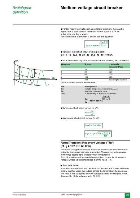
I (A)<br />
c Short-circuit breaking tests must meet the five following test sequences:<br />
Sequence % Isym. % aperiodic<br />
IMC<br />
IAC<br />
t (s)<br />
component %DC<br />
1 10 ≤ 20<br />
2 20 ≤ 20<br />
3 60 ≤ 20<br />
4 100 ≤ 20<br />
5* 100 according to equation<br />
IDC<br />
* for circuit breakers opening in less than 80 ms<br />
IMC : making current<br />
IAC : periodic component peak value (Isc peak)<br />
Idc : aperiodic component value<br />
%DC : % asymmetry or aperiodic component:<br />
- (Top + Tr)<br />
IDC<br />
τ (1, …, 4)<br />
• 100 = 100 • e<br />
IAC<br />
c Symmetric short-circuit current (in kA):<br />
Isym = IAC<br />
r<br />
c Asymmetric short-circuit current (in kA):<br />
Iasym 2 = I 2 AC + I 2 DC<br />
Iasym = Isym 1 + 2( %DC ) 2<br />
100<br />
Rated Transient Recovery Voltage (TRV)<br />
(cf. § 4.102 IEC 60 056)<br />
This is the voltage that appears across the terminals of a circuit breaker<br />
pole after the current has been interrupted. The recovery voltage wave<br />
form varies according to the real circuit configuration.<br />
A circuit breaker must be able to break a given current for all recovery<br />
voltages whose value remains less than the rated TRV.<br />
c First pole factor<br />
For three-phase circuits, the TRV refers to the pole that breaks the circuit<br />
initially, in other words the voltage across the terminals of the open pole.<br />
The ratio of this voltage to a simple voltage is called the first pole factor,<br />
it is equal to 1.5 for voltages up to 72.5 kV.<br />
<strong>Schneider</strong> <strong>Electric</strong><br />
Merlin Gerin <strong>MV</strong> <strong>design</strong> <strong>guide</strong><br />
49