MV design guide - Schneider Electric
MV design guide - Schneider Electric
MV design guide - Schneider Electric

Create successful ePaper yourself
Turn your PDF publications into a flip-book with our unique Google optimized e-Paper software.
Design rules<br />
Busbar calculation<br />
Let's check<br />
the thermal withstand<br />
of the busbars!<br />
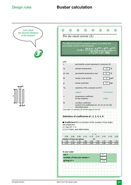
For the rated current (Ir)<br />
The MELSON & BOTH equation allows us to define the<br />
permissible current in the conductor:<br />
I = K • 24.9 (θ - θn)0.61 • S 0.5 • p 0.39<br />
ρ 20 [1+ α (θ - 20)]<br />
with:<br />
I : permissible current expressed in amperes (A)<br />
θn : ambient temperature 40 °C<br />
(θ - θn) : permissible temperature rise* 50 °C<br />
S : busbar cross-section 10 cm 2<br />
e<br />
p : busbar perimeter 22 cm<br />
ρ 20 : resistivity of the conductor at 20°C<br />
copper:<br />
1.83 µΩ cm<br />
a<br />
α : temperature coefficient<br />
for the resistivity: 0.004<br />
e<br />
K : condition coefficient<br />
product of 6 coefficients (k1, k2, k3, k4, k5, k6),<br />
described below<br />
*(see table V in standard CEI 60 694 pages 22 and 23)<br />
Definition of coefficients k1, 2, 3, 4, 5, 6:<br />
c Coefficient k1 is a function of the number of bar strips<br />
per phase for:<br />
v 1 bar (k1 = 1)<br />
v 2 or 3 bars, see table below:<br />
e / a<br />
0.05 0.06 0.08 0.10 0.12 0.14 0.16 0.18 0.20<br />
number of bars per phase k1<br />
2 1.63 1.73 1.76 1.80 1.83 1.85 1.87 1.89 1.91<br />
3 2.40 2.45 2.50 2.55 2.60 2.63 2.65 2.68 2.70<br />
In our case:<br />
e/a =<br />
number of bars per phase =<br />
giving k1 =<br />
0.1<br />
2<br />
1.80<br />
<strong>Schneider</strong> <strong>Electric</strong><br />
Merlin Gerin <strong>MV</strong> <strong>design</strong> <strong>guide</strong><br />
31