MV design guide - Schneider Electric
MV design guide - Schneider Electric
MV design guide - Schneider Electric

Create successful ePaper yourself
Turn your PDF publications into a flip-book with our unique Google optimized e-Paper software.
Design rules<br />
Short-circuit currents<br />
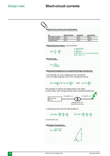
c Synchronous motors and compensators<br />
Xsc Sub-transient transient permanent<br />
high speed motors 15 % 25 % 80 %<br />
low speed motors 35 % 50 % 100 %<br />
compensators 25 % 40 % 160 %<br />
c Asynchronous motors only sub-transient<br />
Ir<br />
Z(Ω) =<br />
Id<br />
c Fault arcing<br />
•<br />
U 2<br />
Sr<br />
Isc z 5 to 8 Ir<br />
Isc z 3∑ Ir,<br />
contribution to Isc by current feedback<br />
(with I rated = Ir)<br />
Isc<br />
Id =<br />
1.3 to 2<br />
c Equivalent impedance of a component through a transformer<br />
v for example, for a low voltage fault, the contribution<br />
of an HV cable upstream of an HV/LV transformer will be:<br />
R2 = R1( U2 ) 2<br />
U1<br />
et<br />
X2 = X1 ( U2 ) 2<br />
U1<br />
ainsi<br />
U2<br />
Z2 = Z1 ( ) 2<br />
U1<br />
This equation is valid for all voltage levels in the cable,<br />
in other words, even through several series-mounted transformers.<br />
Power source<br />
Ra, Xa<br />
HV cable R1, X1<br />
n<br />
transformer RT, XT<br />
impedance at primary<br />
LV cable R2, X2<br />
A<br />
v Impedance seen from the fault location A:<br />
∑ R = R2 + RT R1 Ra<br />
+ + ∑ X =<br />
n 2 n 2 n 2 X2 + XT+ X1<br />
+<br />
n 2 n 2<br />
n: transformation ratio<br />
Xa<br />
n 2<br />
c Triangle of impedances<br />
Z = (R 2 + X 2 )<br />
Z<br />
X<br />
ϕ<br />
R<br />
16 Merlin Gerin <strong>MV</strong> <strong>design</strong> <strong>guide</strong> <strong>Schneider</strong> <strong>Electric</strong>