

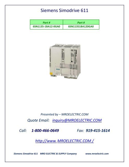
6SN1135-1BA12-0GA0 - FANUC & SIEMENS CNC
6SN1135-1BA12-0GA0 - FANUC & SIEMENS CNC
6SN1135-1BA12-0GA0 - FANUC & SIEMENS CNC

You also want an ePaper? Increase the reach of your titles
YUMPU automatically turns print PDFs into web optimized ePapers that Google loves.
Siemens Simodrive 611<br />
Part # Part #<br />
<strong>6SN1135</strong>-<strong>1BA12</strong>-<strong>0GA0</strong> <strong>6SN1135</strong><strong>1BA12</strong><strong>0GA0</strong><br />
Presented by – MROELECTRIC.COM<br />
Quote Email: inquiry@MROELECTRIC.COM<br />
Call: 1-800-466-0649 Fax: 919-415-1614<br />
http://www. MROELECTRIC.COM /<br />
Siemens Simodrive 611 MRO ELECTRIC & SUPPLY Company www.mroelectric.com
SIMODRIVE 611 <br />
Drive Converter<br />
Configuration Manual · 02/2012<br />
SIMODRIVE<br />
s
Preface, Table of Contents<br />
SIMODRIVE 611 digital<br />
Drive Converters<br />
Configuration Manual<br />
Valid for<br />
Equipment series 6SN11–<br />
Overview of the<br />
Drive System<br />
System Configuration<br />
Motor Selection and<br />
Position/Speed Sensing<br />
Control Units<br />
Power Modules<br />
Infeed Modules<br />
Line Supply Connection<br />
Important Circuit Information<br />
Cabinet Design and EMC<br />
Connection Diagrams<br />
Service and Spare Parts<br />
Dimension Drawings<br />
Abbreviations and Terminology<br />
References<br />
Certificates/<br />
Declarations of Conformity<br />
Index<br />
1<br />
2<br />
3<br />
4<br />
5<br />
6<br />
7<br />
8<br />
9<br />
10<br />
11<br />
12<br />
A<br />
B<br />
C<br />
D<br />
02/2012 Edition
3ls<br />
SIMODRIVE ® documentation<br />
Printing history<br />
Brief details of this edition and previous editions are listed below.<br />
The current configuring manual replaces the previous version.<br />
The status of each edition is shown by the code in the ”Remarks” column.<br />
Status code in the ”Remarks” column:<br />
A.... New documentation<br />
B.... Unrevised reprint with new Order No.<br />
C.... Revised edition with new status<br />
If technical changes have been made on the page since the last edition, this is indicated by a<br />
new edition coding in the header on that page.<br />
Edition Order No. Remarks<br />
04.93 6SN1060–0AA01–0BA0 A<br />
08.93 6SN1197–0AA00–0BP0 C<br />
12.94 6SN1197–0AA00–0BP1 C<br />
11.95 6SN1197–0AA00–0BP2 C<br />
02.98 6SN1197–0AA00–0BP3 C<br />
08.98 6SN1197–0AA00–0BP4 C<br />
05.01 6SN1197–0AA00–0BP5 C<br />
02.03 6SN1197–0AA00–0BP6 C<br />
10.04 6SN1197–0AA00–0BP7 C<br />
11.05 6SN1197–0AA00–0BP8 C<br />
02.07 6SN1197–0AA00–1BP0 C<br />
05.08 6SN1197–0AA00–1BP1 C<br />
02.12 6SN1197–0AA00–1BP2 C<br />
Trademarks<br />
All products mentioned may be trademarks or product designations of Siemens AG or their suppliers,<br />
whose use by third parties for their own purposes may infringe the rights of the trademark owners.<br />
We have checked that the contents of this publication agree with the<br />
hardware and software described here. Nevertheless, differences might<br />
exist and therefore we cannot guarantee that they are completely identical.<br />
The information in this document is regularly checked and necessary<br />
corrections are included in reprints. Suggestions for improvement are also<br />
welcome.<br />
© Siemens AG 2012 All rights reserved.<br />
Subject to change without prior notice.<br />
Printed in the Federal Republic of Germany<br />
Siemens–Aktiengesellschaft
Foreword<br />
Reader’s note<br />
The Configuration Manual describes a reference state, which when<br />
observed, ensures the required reliable operation and compliance with<br />
the standards that have been taken into account.<br />
For deviations from the requirements laid down in the Configuration<br />
Manual, suitable measures must be applied, for example, measurements,<br />
securing or verifying that the required reliable operation is guaranteed<br />
and that the standards to be taken into account are complied<br />
with from a regulatory perspective.<br />
The documentation must be completely read, understood and taken<br />
into account before the devices are commissioned.<br />
If parts of the documentation have not been adequately understood,<br />
then please contact your local Siemens person before you continue to<br />
work with the devices.<br />
The contents of this document are neither part of an earlier or existing<br />
agreement, commitment or contractual relationship, nor do they<br />
change this. Siemens is obliged to fulfill all requirements specified in<br />
the applicable sales contract, which also contains all the valid terms of<br />
warranty.<br />
Any statements contained herein neither create new warranties nor<br />
modify the existing warranty.<br />
Structure of the<br />
documentation<br />
Additional information<br />
My Documentation<br />
Manager<br />
Training<br />
The SIMODRIVE documentation is subdivided into the following levels:<br />
General Documentation/Catalogs<br />
User Documentation<br />
Manufacturer/Service Documentation<br />
You can find information on the following topics under the following link:<br />
Ordering documentation/overview of documents<br />
Links to download documents<br />
Using documentation online (searching and scanning through manuals/information)<br />
http://www.siemens.com/motioncontrol/docu<br />
If you have any questions regarding the technical documentation (e.g., suggestions,<br />
corrections), then please send an e–mail to the following address<br />
docu.motioncontrol@siemens.com<br />
Information is provided under the following link as to how you can individually<br />
compile documentation based on Siemens content, and adapt this for your own<br />
machine documentation:<br />
http://www.siemens.com/mdm<br />
Information about SITRAIN – Siemens training courses for products, systems<br />
and solutions in automation technology – is provided under the following link:<br />
http://www.siemens.com/sitrain<br />
© Siemens AG 2012 All Rights Reserved<br />
SIMODRIVE 611 Configuration Manual (PJU) – 02/2012 Edition<br />
v
Forword 02.12 05.01<br />
1.2 Systemkonfiguration 1<br />
FAQs<br />
You can find Frequently Asked Questions in the Service&Support pages under<br />
Product Support:<br />
http//support.automation.siemens.com<br />
Target group<br />
Technical Support<br />
This documentation addresses machine manufacturing companies (OEMs) that<br />
wish to configure, construct and commission a drive line–up based on<br />
SIMODRIVE components.<br />
Local country telephone numbers for technical support are provided in the Internet<br />
under Contact:<br />
http://www.siemens.com automation/service&support<br />
Certificates<br />
You will find the certificates for the products described in this documentation in<br />
the Internet: http://www.support.automation.siemens.com<br />
under the Product/Order No. 15257461<br />
or contact the relevant branch office of the A&D MC group of Siemens AG.<br />
All declarations of conformity and certificates such as CE, UL, etc., are performed<br />
with the system components described in the associated Configuration<br />
Manuals or catalogs and, thus, are only valid if the described components are<br />
used in the device or facility.<br />
Note<br />
The use of components not released by Siemens may require the user to<br />
prepare new certificates/declarations of conformity.<br />
vi<br />
© Siemens AG 2012 All Rights Reserved<br />
SIMODRIVE 611 Configuration Manual (PJU) – 02/2012 Edition
05.01 02.12<br />
Forword<br />
Repairs<br />
Note<br />
Repairs may be performed only by workshops authorized by Siemens who<br />
must use genuine spare parts. Unauthorized repairs and the use of other spare<br />
parts can result in personal injuries and property damage as well as loss of UL<br />
approvals and safety functions, such as Safety Integrated.<br />
!<br />
Warning<br />
SIMODRIVE converters are used in high voltage installations and are operated<br />
at voltages that when touched can cause serious injuries or death!<br />
Proper use<br />
Note the following:<br />
!<br />
Warning<br />
Siemens products may only be used for the intended use in applications<br />
described in the catalog and the associated technical documentation. If<br />
third–party products and components are used, then these must either be<br />
recommended or certified by Siemens. The perfect and safe operation of<br />
products assumes that they have been correctly transported, correctly stored,<br />
located, mounted, installed, commissioned, operated and maintained. The<br />
permissible environmental conditions must be complied with.<br />
Information and instructions in the associated documentation must be<br />
observed.<br />
Definition:<br />
Who are qualified<br />
personnel?<br />
Objectives<br />
Setup and operation of the device/equipment/system in question must only be<br />
performed using this documentation. Commissioning and operation of a device/<br />
system may only be performed by qualified personnel. Qualified personnel as<br />
referred to in the safety instructions in this documentation are persons authorized<br />
to start up, ground, and label devices, systems, and circuits in accordance<br />
with the relevant safety standards.<br />
This Configuration Manual provides all of the detailed information required to<br />
use and handle SIMODRIVE components.<br />
Should you wish for additional information or should exceptional problems arise<br />
that are not addressed in sufficient detail in this manual, you can request the<br />
required information from your local Siemens office.<br />
The Configuration Manual describes a modular drive system. It is permissible to<br />
use the constellations and general versions described here. All other combinations<br />
must be separately and individually released by Siemens.<br />
© Siemens AG 2012 All Rights Reserved<br />
SIMODRIVE 611 Configuration Manual (PJU) – 02/2012 Edition<br />
vii
Forword 12.06 02.07 11.05 05.01<br />
Information for<br />
using this Manual<br />
The following should be observed when using this manual:<br />
1. Help: The following help is available for the reader:<br />
Complete table of contents<br />
Header line (as orientation):<br />
the main chapter is in the upper header line<br />
the sub–chapter is in the lower header line<br />
Appendix with<br />
– Abbreviations and List of References<br />
– Index<br />
If you require information regarding a specific term, then look for this in<br />
the Appendix under the Chapter ”Index”.<br />
The Chapter number as well as the page number is specified where information<br />
on this term can be found.<br />
2. Edition of the documentation:<br />
The history of the document editions is summarized in the printing history.<br />
The header of the document indicates the current edition (12/2006).<br />
Reader’s note<br />
Only the digital components for a SIMODRIVE group with High Performance/<br />
High Standard and 611 universal modules are described in Edition A10.04 and<br />
higher. Please refer to the overview in Chapter 4.1 regarding from which<br />
software releases, use is possible.<br />
The descriptions for the relevant controls in the Configuration Manual, Edition<br />
02.03, still remain valid for the analog components that have been discontinued<br />
(not for new configurations)!<br />
Safety information<br />
This documentation contains information that must be observed to ensure your<br />
personal safety and to prevent material damage. The instructions for your personal<br />
safety are marked by a warning triangle. Instructions relating solely to<br />
material damage are not marked by a warning triangle. The warnings appear in<br />
decreasing order of risk as given below.<br />
!<br />
Danger<br />
indicates that death or serious injury will result if proper precautions are not<br />
taken.<br />
!<br />
Warning<br />
indicates that death or serious injury may result if proper precautions are not<br />
taken.<br />
viii<br />
© Siemens AG 2012 All Rights Reserved<br />
SIMODRIVE 611 Configuration Manual (PJU) – 02/2012 Edition
05.01 05.08<br />
Forword<br />
!<br />
Caution<br />
with a safety alert signal indicates that minor personal injury can result if proper<br />
precautions are not taken.<br />
Caution<br />
without a safety alert symbol, indicates that property damage can result if<br />
proper precautions are not taken.<br />
Notice<br />
indicates that an undesirable result or state may arise if the relevant note is not<br />
observed.<br />
Additional<br />
information<br />
Note<br />
This symbol indicates important information about the product or part of the<br />
document, where the reader should take special note.<br />
Reader’s note<br />
This symbol is shown, if it relates to important information which the reader<br />
must observe.<br />
Technical information<br />
!<br />
Warning: High leakage current<br />
As a result of the high switching frequencies, capacitances (parasitic and<br />
integrated) with respect to ground may cause high leakage currents. This is the<br />
reason that a permanent PE connection is required at the control cabinet and<br />
at the line filter!<br />
Measures according to EN 50178/94 Part 5.3.2.1 must be implemented, e.g.<br />
1. Copper protective conductor with a minimum cross–section of 10 mm 2<br />
should be connected, or<br />
2. A second conductor should be connected in parallel with the protective<br />
conductor through separate terminals.<br />
This conductor must also fully meet the requirements for PE conductors<br />
according to IEC 364–5–543.<br />
© Siemens AG 2012 All Rights Reserved<br />
SIMODRIVE 611 Configuration Manual (PJU) – 02/2012 Edition<br />
ix
Forword 02.12 05.01<br />
Note<br />
The SIMODRIVE 611 drive converter system can be directly connected to TN<br />
line supplies with rated voltages 3–ph. 380 V AC (with derating), 3–ph. 400 V<br />
AC, 3–ph. 415 V AC and 3–ph. 480 V AC. Matching transformers, which are<br />
tailored to the system, are available to connect the system to other line supply<br />
types, for example, to IT or TT line supplies.<br />
Upstream devices providing protection against hazardous leakage currents or<br />
for fire protection (such as residual–current protective devices) must be<br />
AC/DC–sensitive in accordance with the requirements of DIN EN 50178. In the<br />
case of other residual current protective devices, a transformer with separate<br />
windings must be connected upstream of the converter for purposes of<br />
decoupling. See Chapter 7.<br />
!<br />
Warning<br />
When electrical equipment is operated, certain parts of this equipment are<br />
inevitably under dangerous voltage.<br />
Incorrect handling of these units, i.e. not observing the warning information, can<br />
therefore lead to death, severe bodily injury or significant material damage.<br />
Only appropriately qualified personnel may commission/start up this<br />
equipment.<br />
These personnel must be thoroughly familiar with all warnings and<br />
maintenance procedures described in these operating instructions.<br />
Perfect, safe and reliable operation of the equipment assumes that it has been<br />
appropriately transported and repaired and professionally stored, mounted and<br />
installed as well as carefully operated and serviced. Failure to observe these<br />
requirements can endanger the user (electrical shock, fire hazard) or damage<br />
the device.<br />
Hazardous axis motion can occur when working with the equipment.<br />
Further, all of the relevant national, local land plant/system–specific regulations<br />
and specifications must be taken into account.<br />
!<br />
Caution<br />
The DC link discharge voltage hazard warning in the local language must be<br />
clearly attached to the appropriate modules.<br />
Note<br />
When handling cables, please observe the following:<br />
are not damaged<br />
they may not be stressed,<br />
they may not come into contact with rotating components.<br />
x<br />
© Siemens AG 2012 All Rights Reserved<br />
SIMODRIVE 611 Configuration Manual (PJU) – 02/2012 Edition
05.01 05.08<br />
Forword<br />
Notice<br />
M600 and M500 are not PE voltages. Hazardous voltages of between<br />
300 ... 400 V with respect to PE are present at the terminals. These potentials<br />
(voltages) may not be connected to PE.<br />
Note<br />
The machine builder must ensure that the voltage drop between the start of the<br />
consumer’s installation and the power drive system (PDS) does not exceed 4%<br />
when operating with rated values.<br />
!<br />
Warning<br />
The ”protective separation” can only be guaranteed when using the<br />
components permitted/certified by Siemens for the system.<br />
”Protective separation” can only be guaranteed when it is absolutely certain<br />
that the system components have the appropriate degree of protection.<br />
The ensure ”protective separation”, the shield of the brake cable must be<br />
connected to PE through the largest possible surface area.<br />
”Protective separation” is required between the temperature sensor and motor<br />
winding.<br />
If these limitations and constraints are not carefully observed then this can<br />
result in injury due to electric shock.<br />
!<br />
Warning<br />
Start–up/commissioning is absolutely prohibited until it has been ensured that<br />
the machine in which the components described here are to be installed, fulfills<br />
the regulations/specifications of the Directive 89/392/EEC. If this is not<br />
observed, this can result in injury.<br />
!<br />
Warning<br />
The information and instructions in all of the documentation supplied and any<br />
other instructions must always be observed to eliminate hazardous situations<br />
and damage.<br />
<br />
<br />
For special versions of the machines and equipment, the information in the<br />
associated catalogs and quotations applies.<br />
Further, all of the relevant national, local land plant/system–specific<br />
regulations and specifications must be taken into account.<br />
All work should be undertaken with the system in a no–voltage condition!<br />
If this is not observed, this can result in injury.<br />
© Siemens AG 2012 All Rights Reserved<br />
SIMODRIVE 611 Configuration Manual (PJU) – 02/2012 Edition<br />
xi
Forword 12.07 05.01<br />
!<br />
Warning<br />
Even after the disconnection of all power, a dangerous residual voltage as high<br />
as 60 V DC can still be present. For capacitor modules, this hazardous voltage<br />
can be present for up to 30 min.<br />
In order to ensure that no hazardous voltages are present, the voltage must be<br />
first carefully measured (generator principle when motors are rotating). If this is<br />
not observed, then this can result in injury due to electric shock.<br />
For this reason, opening the device or removing the cover is permitted only<br />
after up to 30 minutes have elapsed (depending on the degree of expansion)<br />
since the device was switched to the voltage–free state. All covers must be<br />
reattached before the line voltage is switched on. Operation of the plant with<br />
damaged DC link covers is not permitted!<br />
Danger of death!<br />
Touching live terminals, cables or device parts can result in serious injury or<br />
death!<br />
!<br />
Warning<br />
Do not switch off devices, e.g. using a line supply isolating device (main<br />
switch), before disabling the pulse inhibit (T 48) on the infeed/regenerative<br />
feedback modules. Otherwise, the device can be destroyed along with other<br />
devices in the control cabinet.<br />
!<br />
Warning<br />
The rated current of the connected motor must match the rated converter<br />
current. If this is not the case, then the protection of the motor cables is no<br />
longer guaranteed. The cross–section of the motor feeder cable must be<br />
dimensioned for the rated drive converter current. If this is not carefully<br />
observed, cables can overheat and can even cause an equipment fire.<br />
Caution<br />
When using mobile radios (e.g. cellular phones, mobile phones, 2–way radios)<br />
with a transmission power of > 1 W close to the equipment (< 1.5 m) the<br />
function of the equipment can be disturbed.<br />
Note<br />
This device/module is an open–type device corresponding to UK 50 and, thus,<br />
may only be operated in enclosures/cabinets that ensure protection against<br />
mechanical damage. To ensure protection against mechanical damage, the<br />
devices may only be operated in enclosures/cabinets with degree of protection<br />
IP54 in accordance with EN 60529.<br />
xii<br />
© Siemens AG 2012 All Rights Reserved<br />
SIMODRIVE 611 Configuration Manual (PJU) – 02/2012 Edition
05.01 02.12<br />
Forword<br />
Note<br />
The terminal blocks of the SIMODRIVE 611 modules are used for electrical<br />
connection of the particular module. If the terminal blocks are used for another<br />
purpose (e.g. to carry the module), this can damage the module. If the<br />
insulation is damaged, then this can cause injury due to electric shock.<br />
Note<br />
For a minimum fault current, the machine manufacturer must ensure that the<br />
upstream overcurrent protection devices trip within 5 s (see Chapter 7.3; Table<br />
7–5 and Fig. 7–8<br />
Note<br />
The following secondary conditions/limitations must be carefully observed if the<br />
machine is subject to a high–voltage test:<br />
1. Power–down the unit.<br />
2. Withdraw the overvoltage module in order to prevent the voltage limiting<br />
responding.<br />
3. Disconnect the line filter so that the test voltage does not dip.<br />
4. Connect M600 to PE through resistor 100 kΩ (the grounding clip in the NE<br />
modules is open). In the factory, the units are subject to a high–voltage test<br />
at 2.25 kV DC phase–PE. The NE modules are shipped with the grounding<br />
clip open.<br />
5. The maximum permissible voltage for a high–voltage machine test is<br />
1.kV DC phase–PE.<br />
!<br />
Danger<br />
The control and drive components for a power drive system (PDS) are allowed<br />
for industrial and commercial use in industrial networks. Their use in public<br />
networks requires a different configuration and/or additional measures.<br />
© Siemens AG 2012 All Rights Reserved<br />
SIMODRIVE 611 Configuration Manual (PJU) – 02/2012 Edition<br />
xiii
Forword 02.07 05.01<br />
ESDS information<br />
and instructions<br />
ElectroStatic Discharge Sensitive Devices<br />
Components, which can be destroyed by electrostatic discharge are individual<br />
components, integrated circuits, or boards, which when handled, tested, or<br />
transported, could be destroyed by electrostatic fields or electrostatic<br />
discharge. These components are referred to as ESDS (ElectroStatic<br />
Discharge Sensitive Devices).<br />
Handling ESDS modules:<br />
When handling devices which can be damaged by electrostatic discharge,<br />
personnel, workstations and packaging must be well grounded!<br />
Generally, electronic modules may not be touched unless work has to be<br />
carried out on them.<br />
Personnel may only touch components if<br />
– they are continuously grounded through ESDS wristlets,<br />
– they wear ESDS shoes, ESDS shoe grounding strips in conjunction with<br />
an ESDS floor surface.<br />
Boards/modules must only be placed on conductive surfaces (table with<br />
ESDS surface, conductive ESDS foam, ESDS packaging, ESDS transport<br />
container).<br />
Modules may not be brought close to data terminals, monitors or television<br />
sets (minimum clearance to the screen > 10 cm).<br />
Do not bring ESDS–sensitive modules into contact with chargeable and<br />
highly–insulating materials, such as plastic sheets, insulating table tops or<br />
clothing made of synthetic materials.<br />
Measuring work may only be carried out on the components if<br />
– the measuring unit is grounded (e.g. via a protective conductor) or<br />
– when floating measuring equipment is used, the probe is briefly<br />
discharged before making measurements (e.g. a bare–metal control<br />
housing is touched).<br />
!<br />
!<br />
Warning<br />
If static discharge occurs on surfaces or interfaces that cannot be easily<br />
accessed, malfunctions and/or defects will result.<br />
Warning<br />
When the system boots, this represents a critical operating state with increased<br />
risk. In this phase, especially when activating drives, it is not permissible that<br />
personnel are close to the hazardous area.<br />
!<br />
Warning<br />
After hardware and/or software components have been modified or replaced, it<br />
is only permissible that the system runs–up and the drives are activated with<br />
the protective devices closed (could possibly result in death). Personnel shall<br />
not be present within the danger zone.<br />
It may be necessary to carry–out a new, partial or complete acceptance test<br />
after every change or replacement.<br />
Before entering the hazardous area, it should be carefully checked that all of<br />
the drives exhibit stable behavior by briefly moving the drives in both directions<br />
(+/–).<br />
xiv<br />
© Siemens AG 2012 All Rights Reserved<br />
SIMODRIVE 611 Configuration Manual (PJU) – 02/2012 Edition
05.01<br />
Forword<br />
!<br />
Warning<br />
If the ”safe standstill” function or a stop function, Category 0 in accordance with<br />
EN 60204–1, is activated, the motor can no longer provide any torque. As a<br />
result of this, potentially hazardous motion can occur, e.g. for:<br />
When the drive axes are subject to an external force.<br />
Vertical and inclined axes without weight equalization.<br />
Axes that are moving (coasting down).<br />
Direct drives with low friction and self–clocking behavior.<br />
Possible hazards must be clearly identified using a risk analysis that must be<br />
carried out by the manufacturer. Using the assessment based on this risk<br />
analysis, it must be defined as to which additional measures are required (e.g.<br />
external brakes).<br />
!<br />
Warning<br />
If the ”safe standstill” function is activated, when a fault condition occurs, the<br />
mechanical axis system can make a jerky movement (possibility of injury,<br />
crushing) as a result of the principle of operation. The magnitude of this<br />
movement depends on the following parameters:<br />
Design/configuration and mechanical ratios between the motor/mechanical<br />
system.<br />
Speed and acceleration capability of the motor<br />
Magnitude of the selected monitoring clock cycle.<br />
Size of the selected standstill tolerance window.<br />
The danger and warning information above must always be unconditionally observed<br />
in order to avoid personal injury and property damage.<br />
© Siemens AG 2012 All Rights Reserved<br />
SIMODRIVE 611 Configuration Manual (PJU) – 02/2012 Edition<br />
xv
Forword 02.07 05.01<br />
Health and safety<br />
in the workplace<br />
The professional associations for precision and electrical engineering specify<br />
limits for electrical load in the workplace. Compliance with Federal Emission<br />
Control Law is mandatory in the Federal Republic of Germany!<br />
Adherence to the RFI suppression limits for EMC does not also ensure adherence<br />
to the requirements for workplaces.<br />
In particular, machine construction, control cabinet structure, shop environment,<br />
infeed conditions and other installations have a substantial impact on adherence<br />
to the limits required by the trade association for the respective workplace.<br />
Therefore, the operator must always clarify whether wearers of pacemakers<br />
may be employed at the planned workplace without endangering their health.<br />
xvi<br />
© Siemens AG 2012 All Rights Reserved<br />
SIMODRIVE 611 Configuration Manual (PJU) – 02/2012 Edition
05.01 02.07<br />
Forword<br />
Residual risks<br />
When carrying out a risk assessment of the machine in accordance with the EU<br />
Machinery Directive, the machine manufacturer must consider the following<br />
residual risks associated with the control and drive components of a power drive<br />
system (PDS).<br />
1. Unintentional movements of driven machine components during commissioning,<br />
operation, maintenance, and repairs caused by, for example:<br />
– Hardware defects and/or software errors in the sensors, controllers,<br />
actuators, and connection technology<br />
– Response times of the controller and drive<br />
– Operation outside the specification<br />
– Errors when parameterizing, programming and wiring<br />
– Use of radio devices/cellular phones in the immediate vicinity of the<br />
controller<br />
– External effects<br />
2. Exceptional temperatures as well as emissions of light, noise, particles, or<br />
gas caused by, for example:<br />
– Component malfunctions<br />
– Software errors<br />
– Operation outside the specification<br />
– External effects<br />
3. Hazardous shock voltages caused by, for example:<br />
– Component malfunctions<br />
– Static charges<br />
– Operation outside the specification<br />
– Condensation/conductive contamination<br />
– External effects<br />
4. Electrical, magnetic, and electromagnetic fields that can pose a risk to<br />
people with a pacemaker and/or implants if they are too close.<br />
5. Emission of pollutants if components or packaging are not disposed of<br />
properly.<br />
An assessment of the residual risks (see points 1 to 5 above) established that<br />
these risks do not exceed the specified limit values (risk priority number in<br />
accordance with EN 60812 RPZ = 100).<br />
For additional information, refer to the relevant sections of the Configuration<br />
Manual.<br />
At the present time, other known residual risks are:<br />
<br />
Acceleration of the spindle or axes due to:<br />
– Encoder errors, e.g. errors in the absolute measuring system (CD track),<br />
loose contacts in encoder cables or unsuitable encoders.<br />
– Cyclically interchanged phases of the motor connections<br />
(V–W–U instead of U–V–W).<br />
– Interchanged control sense.<br />
– Electric faults (defective components, etc.).<br />
– Operation of a demagnetized synchronous motor with saturation–based<br />
pole position identification.<br />
– Transfer of an incorrect, but plausible actual value in absolute measuring<br />
systems (encoder does not signal an error).<br />
© Siemens AG 2012 All Rights Reserved<br />
SIMODRIVE 611 Configuration Manual (PJU) – 02/2012 Edition<br />
xvii
Forword 02.12 05.01<br />
<br />
If two power transitions in the inverter are simultaneously destroyed, depending<br />
on the motor pole number, this can cause brief axis movement.<br />
– Example: Synchronous motor:<br />
For a 6–pole synchronous motor, the maximum mechanical motion<br />
on the motor shaft can be 30 degrees.<br />
With a ballscrew that is directly driven (e.g. 10 mm per revolution) this<br />
corresponds to a maximum linear motion of approximately 0.8 mm.<br />
– Example, synchronous linear motor:<br />
<br />
<br />
<br />
<br />
<br />
<br />
For a synchronous linear motor, the movement can be a maximum of<br />
one pole width, refer to the Motors Configuration Manual.<br />
For a 1–encoder system, encoder faults are detected by various HW and<br />
SW monitoring functions. It is not permissible that these monitoring functions<br />
are deactivated and they must be parameterized carefully.<br />
Stop function Category 0 according to EN 60204–1 means that the spindle/<br />
axes are not braked. Depending on the kinetic energy involved, they can<br />
coast–down for a long time.<br />
This must be integrated in the logic of the protective door interlocking (e.g.<br />
with a logic operation with the signal n < nx).<br />
Violation of limits may briefly lead to a speed higher than the speed setpoint,<br />
or the axis may pass the defined position to a certain extent, depending on<br />
the dynamic response of the drive and on parameter settings (MD).<br />
Parameterization and programming errors made by the machinery construction<br />
OEM cannot be identified. The required level of safety can only be<br />
assured by a thorough and careful acceptance testing.<br />
When replacing power modules or motors, the same type must always be<br />
used as otherwise the selected parameters may result in different responses.<br />
When an encoder is replaced, the axis involved must be re–calibrated.<br />
If the line infeed units are connected to the line supply, where the minimum<br />
short–circuit current is not reached, then the overcurrent protection devices<br />
will not be able to trip within the appropriate time. There is a risk of fire in the<br />
case of a fault!<br />
<br />
xviii<br />
© Siemens AG 2012 All Rights Reserved<br />
SIMODRIVE 611 Configuration Manual (PJU) – 02/2012 Edition
Contents<br />
1 Overview of the Drive System . . . . . . . . . . . . . . . . . . . . . . . . . . . . . . . . . . . . . . . . 1-25<br />
1.1 Overview of SIMODRIVE 611 . . . . . . . . . . . . . . . . . . . . . . . . . . . . . . . . . 1-25<br />
1.2 Engineering steps . . . . . . . . . . . . . . . . . . . . . . . . . . . . . . . . . . . . . . . . . . . . 1-29<br />
1.3 Engineering a drive . . . . . . . . . . . . . . . . . . . . . . . . . . . . . . . . . . . . . . . . . . 1-31<br />
1.3.1 Calculation of the required DC link power (PZK) for dimensioning<br />
the supply system, infeed unit . . . . . . . . . . . . . . . . . . . . . . . . . . . . . . . . . 1-33<br />
1.3.2 Dynamic operation . . . . . . . . . . . . . . . . . . . . . . . . . . . . . . . . . . . . . . . . . . . 1-34<br />
1.3.3 Braking operation . . . . . . . . . . . . . . . . . . . . . . . . . . . . . . . . . . . . . . . . . . . . 1-35<br />
1.3.4 Calculation of the DC link power (engineering sheet) . . . . . . . . . . . . . . 1-36<br />
1.3.5 Checking the permissible power supply rating . . . . . . . . . . . . . . . . . . . 1-37<br />
2 System Configuration . . . . . . . . . . . . . . . . . . . . . . . . . . . . . . . . . . . . . . . . . . . . . . . . 2-41<br />
2.1 Arrangement of the modules and their mounting . . . . . . . . . . . . . . . . . 2-42<br />
2.1.1 Arrangement of the modules . . . . . . . . . . . . . . . . . . . . . . . . . . . . . . . . . . 2-42<br />
2.1.2 Mounting and installing the modules . . . . . . . . . . . . . . . . . . . . . . . . . . . . 2-45<br />
2.2 Ambient conditions . . . . . . . . . . . . . . . . . . . . . . . . . . . . . . . . . . . . . . . . . . . 2-46<br />
2.3 Motor selection . . . . . . . . . . . . . . . . . . . . . . . . . . . . . . . . . . . . . . . . . . . . . . 2-48<br />
2.4 Position sensing/actual speed value sensing . . . . . . . . . . . . . . . . . . . . 2-49<br />
2.4.1 Position sensing, direct . . . . . . . . . . . . . . . . . . . . . . . . . . . . . . . . . . . . . . . 2-49<br />
2.4.2 Position detection, indirect . . . . . . . . . . . . . . . . . . . . . . . . . . . . . . . . . . . . 2-50<br />
2.4.3 Drive module . . . . . . . . . . . . . . . . . . . . . . . . . . . . . . . . . . . . . . . . . . . . . . . . 2-51<br />
2.5 Power modules . . . . . . . . . . . . . . . . . . . . . . . . . . . . . . . . . . . . . . . . . . . . . . 2-51<br />
2.5.1 Function of the power modules . . . . . . . . . . . . . . . . . . . . . . . . . . . . . . . . 2-52<br />
2.5.2 Connecting–up the power modules . . . . . . . . . . . . . . . . . . . . . . . . . . . . . 2-52<br />
2.6 Control units . . . . . . . . . . . . . . . . . . . . . . . . . . . . . . . . . . . . . . . . . . . . . . . . 2-53<br />
2.6.1 General . . . . . . . . . . . . . . . . . . . . . . . . . . . . . . . . . . . . . . . . . . . . . . . . . . . . 2-53<br />
2.6.2 AC motors . . . . . . . . . . . . . . . . . . . . . . . . . . . . . . . . . . . . . . . . . . . . . . . . . . 2-53<br />
2.6.3 Modules included in the scope of supply . . . . . . . . . . . . . . . . . . . . . . . . 2-53<br />
2.6.4 NCU box for SINUMERIK 840D . . . . . . . . . . . . . . . . . . . . . . . . . . . . . . . 2-54<br />
2.7 Infeed modules . . . . . . . . . . . . . . . . . . . . . . . . . . . . . . . . . . . . . . . . . . . . . . 2-55<br />
2.7.1 Cooling components . . . . . . . . . . . . . . . . . . . . . . . . . . . . . . . . . . . . . . . . . 2-57<br />
2.7.2 Internal cooling . . . . . . . . . . . . . . . . . . . . . . . . . . . . . . . . . . . . . . . . . . . . . . 2-59<br />
2.7.3 External cooling . . . . . . . . . . . . . . . . . . . . . . . . . . . . . . . . . . . . . . . . . . . . . 2-60<br />
3 Motor Selection, Position/Speed Sensing . . . . . . . . . . . . . . . . . . . . . . . . . . . . . 3-63<br />
3.1 Motor selection . . . . . . . . . . . . . . . . . . . . . . . . . . . . . . . . . . . . . . . . . . . . . . 3-63<br />
3.1.1 Motor protection . . . . . . . . . . . . . . . . . . . . . . . . . . . . . . . . . . . . . . . . . . . . . 3-63<br />
3.1.2 Motors with holding brake . . . . . . . . . . . . . . . . . . . . . . . . . . . . . . . . . . . . . 3-63<br />
3.2 Motor encoder . . . . . . . . . . . . . . . . . . . . . . . . . . . . . . . . . . . . . . . . . . . . . . . 3-64<br />
3.3 Indirect position and motor speed sensing . . . . . . . . . . . . . . . . . . . . . . . 3-68<br />
© Siemens AG 2012 All Rights Reserved<br />
SIMODRIVE 611 Configuration Manual (PJU) – 02/2012 Edition<br />
xix
02.12 05.01<br />
3.4 Direct position sensing . . . . . . . . . . . . . . . . . . . . . . . . . . . . . . . . . . . . . . . 3-68<br />
3.4.1 Encoder systems that can be evaluated . . . . . . . . . . . . . . . . . . . . . . . . . 3-68<br />
3.4.2 Encoder power supply . . . . . . . . . . . . . . . . . . . . . . . . . . . . . . . . . . . . . . . . 3-72<br />
3.4.3 Encoder power supply for SSI encoders . . . . . . . . . . . . . . . . . . . . . . . . 3-74<br />
3.4.4 Signal amplifier electronics . . . . . . . . . . . . . . . . . . . . . . . . . . . . . . . . . . . . 3-76<br />
3.5 Overview, position sensing . . . . . . . . . . . . . . . . . . . . . . . . . . . . . . . . . . . . 3-78<br />
3.6 Ordering information . . . . . . . . . . . . . . . . . . . . . . . . . . . . . . . . . . . . . . . . . 3-80<br />
4 Control Units . . . . . . . . . . . . . . . . . . . . . . . . . . . . . . . . . . . . . . . . . . . . . . . . . . . . . . . . 4-81<br />
4.1 Closed–loop control with digital setpoint interface . . . . . . . . . . . . . . . . 4-83<br />
4.1.1 Interface overview, closed–loop drive control . . . . . . . . . . . . . . . . . . . . 4-87<br />
4.2 ”SIMODRIVE 611 universal HRS” control board . . . . . . . . . . . . . . . . . . 4-91<br />
4.2.1 Control board for 1 or 2 axes . . . . . . . . . . . . . . . . . . . . . . . . . . . . . . . . . . 4-93<br />
4.2.2 Description of the terminals and interfaces . . . . . . . . . . . . . . . . . . . . . . 4-98<br />
4.3 ”HLA module” control board . . . . . . . . . . . . . . . . . . . . . . . . . . . . . . . . . . . 4-104<br />
4.3.1 System overview . . . . . . . . . . . . . . . . . . . . . . . . . . . . . . . . . . . . . . . . . . . . 4-105<br />
4.3.2 Wiring . . . . . . . . . . . . . . . . . . . . . . . . . . . . . . . . . . . . . . . . . . . . . . . . . . . . . . 4-107<br />
4.3.3 Test sockets (diagnostics) . . . . . . . . . . . . . . . . . . . . . . . . . . . . . . . . . . . . . 4-111<br />
4.4 ”ANA module” control board . . . . . . . . . . . . . . . . . . . . . . . . . . . . . . . . . . . 4-112<br />
4.4.1 System overview . . . . . . . . . . . . . . . . . . . . . . . . . . . . . . . . . . . . . . . . . . . . 4-113<br />
4.4.2 Wiring . . . . . . . . . . . . . . . . . . . . . . . . . . . . . . . . . . . . . . . . . . . . . . . . . . . . . . 4-115<br />
4.4.3 Bus interfaces . . . . . . . . . . . . . . . . . . . . . . . . . . . . . . . . . . . . . . . . . . . . . . . 4-119<br />
5 Power Modules . . . . . . . . . . . . . . . . . . . . . . . . . . . . . . . . . . . . . . . . . . . . . . . . . . . . . . 5-121<br />
5.1 Description . . . . . . . . . . . . . . . . . . . . . . . . . . . . . . . . . . . . . . . . . . . . . . . . . 5-121<br />
5.2 Operating modes . . . . . . . . . . . . . . . . . . . . . . . . . . . . . . . . . . . . . . . . . . . . 5-123<br />
5.3 Technical data . . . . . . . . . . . . . . . . . . . . . . . . . . . . . . . . . . . . . . . . . . . . . . . 5-124<br />
5.4 Current reduction/derating . . . . . . . . . . . . . . . . . . . . . . . . . . . . . . . . . . . . 5-128<br />
5.4.1 Pulse frequency power modules . . . . . . . . . . . . . . . . . . . . . . . . . . . . . . . 5-128<br />
5.4.2 Temperature–dependent derating . . . . . . . . . . . . . . . . . . . . . . . . . . . . . . 5-130<br />
5.4.3 Installation height–dependent derating . . . . . . . . . . . . . . . . . . . . . . . . . . 5-130<br />
5.4.4 Calculation examples . . . . . . . . . . . . . . . . . . . . . . . . . . . . . . . . . . . . . . . . . 5-131<br />
5.5 Operating power modules from an unregulated infeed . . . . . . . . . . . . 5-134<br />
5.6 Interfaces and terminals . . . . . . . . . . . . . . . . . . . . . . . . . . . . . . . . . . . . . . 5-136<br />
5.6.1 Interface overview . . . . . . . . . . . . . . . . . . . . . . . . . . . . . . . . . . . . . . . . . . . 5-136<br />
5.6.2 Connectable cable cross–sections . . . . . . . . . . . . . . . . . . . . . . . . . . . . . 5-137<br />
5.6.3 Motor terminals A1 and A2 . . . . . . . . . . . . . . . . . . . . . . . . . . . . . . . . . . . . 5-138<br />
6 Infeed Modules . . . . . . . . . . . . . . . . . . . . . . . . . . . . . . . . . . . . . . . . . . . . . . . . . . . . . . 6-141<br />
6.1 Description . . . . . . . . . . . . . . . . . . . . . . . . . . . . . . . . . . . . . . . . . . . . . . . . . 6-141<br />
6.2 Interface overview . . . . . . . . . . . . . . . . . . . . . . . . . . . . . . . . . . . . . . . . . . . 6-147<br />
6.2.1 Interface overview, NE modules . . . . . . . . . . . . . . . . . . . . . . . . . . . . . . . 6-147<br />
6.2.2 5 kW UI module interface overview . . . . . . . . . . . . . . . . . . . . . . . . . . . . . 6-150<br />
6.2.3 Cable cross–sections that can be connected . . . . . . . . . . . . . . . . . . . . 6-152<br />
6.2.4 Three–conductor connection (standard circuit) . . . . . . . . . . . . . . . . . . . 6-153<br />
6.2.5 Description of the interfaces and functions . . . . . . . . . . . . . . . . . . . . . . 6-154<br />
6.3 Function overview and settings . . . . . . . . . . . . . . . . . . . . . . . . . . . . . . . . 6-162<br />
xx<br />
© Siemens AG 2012 All Rights Reserved<br />
SIMODRIVE 611 Configuration Manual (PJU) – 02/2012 Edition
05.01 02.12<br />
6.4 Technical data . . . . . . . . . . . . . . . . . . . . . . . . . . . . . . . . . . . . . . . . . . . . . . . 6-165<br />
6.4.1 General information . . . . . . . . . . . . . . . . . . . . . . . . . . . . . . . . . . . . . . . . . . 6-165<br />
6.4.2 Permissible duty cycles/derating . . . . . . . . . . . . . . . . . . . . . . . . . . . . . . . 6-169<br />
6.4.3 Technical data of the supplementary components . . . . . . . . . . . . . . . . 6-172<br />
6.5 HFD reactor . . . . . . . . . . . . . . . . . . . . . . . . . . . . . . . . . . . . . . . . . . . . . . . . . 6-174<br />
6.5.1 Assignment of the HFD reactors/damping resistors to<br />
the NE modules . . . . . . . . . . . . . . . . . . . . . . . . . . . . . . . . . . . . . . . . . . . . . 6-175<br />
6.6 Monitoring module . . . . . . . . . . . . . . . . . . . . . . . . . . . . . . . . . . . . . . . . . . . 6-179<br />
6.6.1 Integration into the overall system . . . . . . . . . . . . . . . . . . . . . . . . . . . . . . 6-179<br />
6.6.2 Technical data (supplement to the general technical data) . . . . . . . . . 6-179<br />
6.6.3 Mode of operation . . . . . . . . . . . . . . . . . . . . . . . . . . . . . . . . . . . . . . . . . . . 6-181<br />
6.7 DC link options . . . . . . . . . . . . . . . . . . . . . . . . . . . . . . . . . . . . . . . . . . . . . . 6-183<br />
6.7.1 Capacitor module with 2.8 mF, 4.1 mF or 20 mF . . . . . . . . . . . . . . . . . 6-183<br />
6.7.2 Pulsed resistor module and unregulated line supply infeed<br />
with pulsed resistor . . . . . . . . . . . . . . . . . . . . . . . . . . . . . . . . . . . . . . . . . . 6-191<br />
6.7.3 External pulsed resistors . . . . . . . . . . . . . . . . . . . . . . . . . . . . . . . . . . . . . . 6-194<br />
6.7.4 Engineering information is applicable for UI 5 kW, 10 kW, 28 kW<br />
and PR module . . . . . . . . . . . . . . . . . . . . . . . . . . . . . . . . . . . . . . . . . . . . . . 6-197<br />
7 Line Supply Connection . . . . . . . . . . . . . . . . . . . . . . . . . . . . . . . . . . . . . . . . . . . . . 7-199<br />
7.1 Line supply connection conditions for line supply infeed . . . . . . . . . . . 7-199<br />
7.2 Voltage matching . . . . . . . . . . . . . . . . . . . . . . . . . . . . . . . . . . . . . . . . . . . . 7-205<br />
7.2.1 General . . . . . . . . . . . . . . . . . . . . . . . . . . . . . . . . . . . . . . . . . . . . . . . . . . . . 7-205<br />
7.2.2 Line supply types . . . . . . . . . . . . . . . . . . . . . . . . . . . . . . . . . . . . . . . . . . . . 7-205<br />
7.2.3 Minimum cross–sections for PE (protective conductor)/equipotential<br />
bonding conductor . . . . . . . . . . . . . . . . . . . . . . . . . . . . . . . . . . . . . . . . . . . 7-209<br />
7.2.4 Transformers . . . . . . . . . . . . . . . . . . . . . . . . . . . . . . . . . . . . . . . . . . . . . . . . 7-210<br />
7.3 Overcurrent protective devices, transformers and main switch . . . . . 7-215<br />
7.3.1 Assignment of the line fuses to the NE modules . . . . . . . . . . . . . . . . . . 7-215<br />
7.3.2 Assigning autotransformers to the I/R modules . . . . . . . . . . . . . . . . . . 7-220<br />
7.3.3 Assigning isolating transformers to the I/R modules . . . . . . . . . . . . . . 7-224<br />
7.3.4 Assignment of the isolating transformer to the UI modules . . . . . . . . . 7-225<br />
7.3.5 Assigning the main switches . . . . . . . . . . . . . . . . . . . . . . . . . . . . . . . . . . 7-226<br />
7.3.6 Use of a leading contact for line isolating device . . . . . . . . . . . . . . . . . 7-226<br />
7.4 Line filters for I/R and UI modules . . . . . . . . . . . . . . . . . . . . . . . . . . . . . . 7-230<br />
7.4.1 General information . . . . . . . . . . . . . . . . . . . . . . . . . . . . . . . . . . . . . . . . . . 7-230<br />
7.4.2 Wideband line filter . . . . . . . . . . . . . . . . . . . . . . . . . . . . . . . . . . . . . . . . . . . 7-232<br />
7.4.3 Line Filter . . . . . . . . . . . . . . . . . . . . . . . . . . . . . . . . . . . . . . . . . . . . . . . . . . . 7-234<br />
7.4.4 Basic line filter for I/R modules . . . . . . . . . . . . . . . . . . . . . . . . . . . . . . . . 7-235<br />
7.4.5 Adapter sets . . . . . . . . . . . . . . . . . . . . . . . . . . . . . . . . . . . . . . . . . . . . . . . . 7-238<br />
8 Important Circuit Information . . . . . . . . . . . . . . . . . . . . . . . . . . . . . . . . . . . . . . . . . 8-239<br />
8.1 General information . . . . . . . . . . . . . . . . . . . . . . . . . . . . . . . . . . . . . . . . . . 8-239<br />
8.2 Infeed modules . . . . . . . . . . . . . . . . . . . . . . . . . . . . . . . . . . . . . . . . . . . . . . 8-242<br />
8.2.1 Connecting several NE modules to a main switch . . . . . . . . . . . . . . . . 8-242<br />
8.2.2 Application, mode of operation and connection of the line contactor . 8-243<br />
8.2.3 Timing diagram for the ready signal in the I/R module . . . . . . . . . . . . . 8-244<br />
8.3 Axis expansion using a monitoring module . . . . . . . . . . . . . . . . . . . . . . 8-245<br />
8.3.1 Connection example, power supply (standard) . . . . . . . . . . . . . . . . . . . 8-245<br />
© Siemens AG 2012 All Rights Reserved<br />
SIMODRIVE 611 Configuration Manual (PJU) – 02/2012 Edition<br />
xxi
02.12 05.01<br />
8.3.2 Connection example, pulse enable . . . . . . . . . . . . . . . . . . . . . . . . . . . . . 8-246<br />
8.3.3 Description of the interfaces and functions . . . . . . . . . . . . . . . . . . . . . . 8-247<br />
8.4 Drive modules . . . . . . . . . . . . . . . . . . . . . . . . . . . . . . . . . . . . . . . . . . . . . . . 8-249<br />
8.4.1 611 feed module with High Performance/High Standard . . . . . . . . . . . 8-249<br />
8.4.2 Description of the interfaces and functions . . . . . . . . . . . . . . . . . . . . . . 8-250<br />
8.5 Start inhibit in the drive modules/safe standstill . . . . . . . . . . . . . . . . . . 8-252<br />
8.5.1 Start inhibit applications . . . . . . . . . . . . . . . . . . . . . . . . . . . . . . . . . . . . . . 8-252<br />
8.5.2 Mode of operation of the start inhibit . . . . . . . . . . . . . . . . . . . . . . . . . . . . 8-253<br />
8.5.3 Connecting–up the start inhibit . . . . . . . . . . . . . . . . . . . . . . . . . . . . . . . . . 8-254<br />
8.5.4 Sequence and timing when using the start inhibit . . . . . . . . . . . . . . . . . 8-256<br />
8.5.5 Checking the start inhibit . . . . . . . . . . . . . . . . . . . . . . . . . . . . . . . . . . . . . . 8-257<br />
8.5.6 Example ”safe standstill” with contactor safety combination . . . . . . . . 8-258<br />
8.5.7 Example, ”safe standstill” for several drive groups . . . . . . . . . . . . . . . . 8-260<br />
8.6 Application examples with SIMODRIVE 611 . . . . . . . . . . . . . . . . . . . . . 8-262<br />
8.6.1 Block diagram of the application example . . . . . . . . . . . . . . . . . . . . . . . 8-262<br />
8.6.2 Function description of the application example . . . . . . . . . . . . . . . . . . 8-263<br />
8.6.3 Safety systems and Standards . . . . . . . . . . . . . . . . . . . . . . . . . . . . . . . . 8-266<br />
8.7 Circuit examples =1 to =9 with SIMODRIVE 611 . . . . . . . . . . . . . . . . . 8-268<br />
8.7.1 Function description, circuit examples =1 to =9 . . . . . . . . . . . . . . . . . . 8-280<br />
8.8 Information and instructions regarding applications<br />
with 611 digital/611 universal . . . . . . . . . . . . . . . . . . . . . . . . . . . . . . . . . . 8-294<br />
8.8.1 Circuit example, 611 digital with SINUMERIK 840D . . . . . . . . . . . . . . . 8-295<br />
8.8.2 Circuits with 611 digital . . . . . . . . . . . . . . . . . . . . . . . . . . . . . . . . . . . . . . . 8-295<br />
8.8.3 Circuits with 611 universal HRS . . . . . . . . . . . . . . . . . . . . . . . . . . . . . . . . 8-296<br />
8.9 Master/slave operation, SIMODRIVE 611 . . . . . . . . . . . . . . . . . . . . . . . 8-297<br />
8.10 Star–delta mode . . . . . . . . . . . . . . . . . . . . . . . . . . . . . . . . . . . . . . . . . . . . . 8-298<br />
8.11 Series reactor in the motor lead . . . . . . . . . . . . . . . . . . . . . . . . . . . . . . . . 8-301<br />
8.12 Induction motor operation . . . . . . . . . . . . . . . . . . . . . . . . . . . . . . . . . . . . . 8-303<br />
8.12.1 Operating several induction motors in parallel . . . . . . . . . . . . . . . . . . . . 8-303<br />
8.12.2 Selecting individual induction motors 611 . . . . . . . . . . . . . . . . . . . . . . . . 8-305<br />
8.13 Operation when the power fails . . . . . . . . . . . . . . . . . . . . . . . . . . . . . . . . 8-307<br />
8.13.1 Application and mode of operation . . . . . . . . . . . . . . . . . . . . . . . . . . . . . 8-307<br />
8.13.2 Functions . . . . . . . . . . . . . . . . . . . . . . . . . . . . . . . . . . . . . . . . . . . . . . . . . . . 8-307<br />
8.13.3 DC link buffering . . . . . . . . . . . . . . . . . . . . . . . . . . . . . . . . . . . . . . . . . . . . . 8-310<br />
8.14 SINUMERIK Safety Integrated . . . . . . . . . . . . . . . . . . . . . . . . . . . . . . . . . 8-311<br />
8.15 Examples of correctly and incorrectly connecting NE<br />
to the line supply . . . . . . . . . . . . . . . . . . . . . . . . . . . . . . . . . . . . . . . . . . . . 8-312<br />
8.15.1 Three–conductor connection to the line supply . . . . . . . . . . . . . . . . . . . 8-312<br />
8.15.2 Six–conductor connection to the line supply . . . . . . . . . . . . . . . . . . . . . 8-316<br />
8.16 VPM Voltage Protection Module . . . . . . . . . . . . . . . . . . . . . . . . . . . . . . . 8-322<br />
8.16.1 General information . . . . . . . . . . . . . . . . . . . . . . . . . . . . . . . . . . . . . . . . . . 8-322<br />
8.16.2 Integration . . . . . . . . . . . . . . . . . . . . . . . . . . . . . . . . . . . . . . . . . . . . . . . . . . 8-324<br />
8.16.3 Mounting . . . . . . . . . . . . . . . . . . . . . . . . . . . . . . . . . . . . . . . . . . . . . . . . . . . 8-333<br />
xxii<br />
© Siemens AG 2012 All Rights Reserved<br />
SIMODRIVE 611 Configuration Manual (PJU) – 02/2012 Edition
05.01 02.12<br />
9 Cabinet Design and EMC . . . . . . . . . . . . . . . . . . . . . . . . . . . . . . . . . . . . . . . . . . . . . 9-335<br />
9.1 Installation and connecting–up regulations . . . . . . . . . . . . . . . . . . . . . . 9-335<br />
9.1.1 Shielded connecting plates . . . . . . . . . . . . . . . . . . . . . . . . . . . . . . . . . . . . 9-338<br />
9.1.2 Mounting conditions, internal cooling . . . . . . . . . . . . . . . . . . . . . . . . . . . 9-341<br />
9.1.3 Two–tier equipment configuration . . . . . . . . . . . . . . . . . . . . . . . . . . . . . . 9-344<br />
9.2 High–voltage test in the system . . . . . . . . . . . . . . . . . . . . . . . . . . . . . . . . 9-346<br />
9.3 Safety of machinery – safety–related parts of controls according<br />
to EN ISO 13849–1:2008 . . . . . . . . . . . . . . . . . . . . . . . . . . . . . . . . . . . . . 9-347<br />
9.3.1 General information . . . . . . . . . . . . . . . . . . . . . . . . . . . . . . . . . . . . . . . . . . 9-347<br />
9.3.2 Safety–related stop functions of electric drive systems according<br />
to DIN EN 61800–5–2 . . . . . . . . . . . . . . . . . . . . . . . . . . . . . . . . . . . . . . . . 9-347<br />
9.3.3 Control modules safety–related circuit . . . . . . . . . . . . . . . . . . . . . . . . . . 9-348<br />
9.3.4 Safety–related circuit infeed modules . . . . . . . . . . . . . . . . . . . . . . . . . . . 9-350<br />
9.3.5 Safety functions . . . . . . . . . . . . . . . . . . . . . . . . . . . . . . . . . . . . . . . . . . . . . 9-351<br />
9.3.6 Principle of STO in a safety function . . . . . . . . . . . . . . . . . . . . . . . . . . . . 9-352<br />
9.3.7 Principle of SS1 in a safety function . . . . . . . . . . . . . . . . . . . . . . . . . . . . 9-353<br />
9.4 Application examples . . . . . . . . . . . . . . . . . . . . . . . . . . . . . . . . . . . . . . . . . 9-354<br />
9.4.1 EMERGENCY STOP at a converter ” SS1 . . . . . . . . . . . . . . . . . . . . . . 9-354<br />
9.4.2 EMERGENCY STOP and protective door monitoring at a<br />
converter ” SS1 . . . . . . . . . . . . . . . . . . . . . . . . . . . . . . . . . . . . . . . . . . . . . 9-360<br />
9.4.3 EMERGENCY STOP and protective door at several<br />
converters ” SS1 . . . . . . . . . . . . . . . . . . . . . . . . . . . . . . . . . . . . . . . . . . . . 9-372<br />
9.5 Using programmable safety components . . . . . . . . . . . . . . . . . . . . . . . . 9-377<br />
10 Connection Diagrams . . . . . . . . . . . . . . . . . . . . . . . . . . . . . . . . . . . . . . . . . . . . . . . . 10-379<br />
11 Spare Parts and Service . . . . . . . . . . . . . . . . . . . . . . . . . . . . . . . . . . . . . . . . . . . . . . 11-383<br />
11.1 Fan . . . . . . . . . . . . . . . . . . . . . . . . . . . . . . . . . . . . . . . . . . . . . . . . . . . . . . . . 11-383<br />
11.2 Terminals . . . . . . . . . . . . . . . . . . . . . . . . . . . . . . . . . . . . . . . . . . . . . . . . . . . 11-386<br />
11.3 DC link covers . . . . . . . . . . . . . . . . . . . . . . . . . . . . . . . . . . . . . . . . . . . . . . . 11-386<br />
11.4 Inspection of the DC link capacitors of the PM modules . . . . . . . . . . . 11-387<br />
12 Dimension Drawings . . . . . . . . . . . . . . . . . . . . . . . . . . . . . . . . . . . . . . . . . . . . . . . . . 12-391<br />
A Abbreviations and Terminology . . . . . . . . . . . . . . . . . . . . . . . . . . . . . . . . . . . . . . A-459<br />
B References . . . . . . . . . . . . . . . . . . . . . . . . . . . . . . . . . . . . . . . . . . . . . . . . . . . . . . . . . . B-463<br />
C Certificates/Declarations of Conformity . . . . . . . . . . . . . . . . . . . . . . . . . . . . . . . C-465<br />
D Index . . . . . . . . . . . . . . . . . . . . . . . . . . . . . . . . . . . . . . . . . . . . . . . . . . . . . . . . . . . . . . . D-479<br />
© Siemens AG 2012 All Rights Reserved<br />
SIMODRIVE 611 Configuration Manual (PJU) – 02/2012 Edition<br />
xxiii
02.12 05.01<br />
xxiv<br />
© Siemens AG 2012 All Rights Reserved<br />
SIMODRIVE 611 Configuration Manual (PJU) – 02/2012 Edition
Overview of the Drive System<br />
1<br />
1<br />
1.1 Overview of SIMODRIVE 611<br />
Supply system<br />
Transformer<br />
(optional)<br />
Chapter 7<br />
Switches, contactors, fuses<br />
Filter<br />
Optional<br />
Reactor<br />
Chapter 6<br />
Infeed<br />
Chapter 4<br />
Chapter 5<br />
Power module<br />
Closed–loop<br />
Closed–l<br />
control<br />
oop<br />
control<br />
E.g.:<br />
611 digital<br />
611 universal<br />
Cable, reactor,<br />
VPM, cable<br />
protection<br />
Chapter 3<br />
Motor<br />
G<br />
Motor with position/<br />
speed sensing<br />
Fig. 1-1<br />
Basic system structure<br />
© Siemens AG 2012 All Rights Reserved<br />
SIMODRIVE 611 Configuration Manual (PJU) – 02/2012 Edition<br />
1-25
1 Overview of the Drive System 10.04 02.12 05.01<br />
1.1 Overview of SIMODRIVE 611<br />
1<br />
Line supply connection<br />
See Chapter 7<br />
Infeed modules<br />
See Chapter 6<br />
Power modules<br />
See Chapter 5<br />
Damping<br />
resistor<br />
HF commutating<br />
reactors<br />
Line filter<br />
TN system<br />
3–ph. 360 V AC with Derating<br />
3–ph. 400 V AC<br />
3–ph. 415 V AC<br />
3–ph. 480 V AC<br />
Infeed/regenerative<br />
feedback module,<br />
internal cooling 1)<br />
Power module<br />
Internal cooling<br />
with internal fan<br />
Line filter<br />
HF commutating<br />
reactor for 28 kW<br />
UI module<br />
Unregulated<br />
infeed module<br />
or<br />
Power<br />
module<br />
External<br />
cooling<br />
Mounting frame<br />
with mounted<br />
fan<br />
600 V DC<br />
Monitoring module<br />
3–ph. 400 V AC<br />
Matching, isolating<br />
transformer<br />
Types, graduated from<br />
3–ph. 200 V AC to<br />
3–ph. 575 V AC for<br />
TN systems<br />
TT systems<br />
<br />
<br />
<br />
Capacitor<br />
module<br />
Refer to<br />
Chapter<br />
6.7.1<br />
Residual current devices<br />
Installation altitude > 2000 m<br />
External<br />
pulsed<br />
resistor 2)<br />
0.3/25 kW<br />
Pulsed<br />
resistor<br />
module<br />
External<br />
pulsed resistor<br />
1.5/25 kW<br />
Power module with<br />
hose cooling<br />
1) Alternatively, external cooling and hose cooling possible.<br />
Version as for the power modules.<br />
2) Only for 28 kW UI module<br />
Fig. 1-2<br />
Overview of the SIMODRIVE 611 drive system<br />
1-26<br />
© Siemens AG 2012 All Rights Reserved<br />
SIMODRIVE 611 Configuration Manual (PJU) – 02/2012 Edition
05.01 10.04 02.12<br />
1 Overview of the Drive System<br />
1.1 Overview of SIMODRIVE 611<br />
Control units<br />
See Chapter 4<br />
Motors<br />
See Chapter 3<br />
1<br />
Control units with analog setpoint interface/PROFIBUS<br />
For 1FT6/1FK/1FN/1FW6–1PH/1FE1 motors<br />
and induction motors<br />
1–axis version (with resolver only)<br />
<br />
<br />
<br />
<br />
2–axis version (resolver and motor encoder)<br />
Standard: analog setpoint interface<br />
Option modules: PROFIBUS DP or TERMINALS<br />
1FK7<br />
Induction motor,<br />
e.g. 1LA<br />
Control units with digital setpoint interface<br />
1PH4<br />
1PH7<br />
For 1FT6/1FT7/1FK7/1PH/1PM/2SP1/1FE1 motors<br />
<br />
2–axis version (with High–Standard control)<br />
– for motor encoders<br />
– additional measuring system, voltage signals<br />
1PH2<br />
1FW6<br />
For 1FT6/1FT7/1FK7/1FN3/1FW6/1PH/1PM/2SP1/1FE1 motors<br />
<br />
<br />
1–axis version (with High–Performance control)<br />
– for motor encoders<br />
– additional measuring system, voltage signals<br />
2–axis version (with High–Performance control)<br />
– for motor encoders<br />
– additional measuring system, voltage signals<br />
EnDat and SSI encoders<br />
1FE1<br />
2SP1<br />
1FN3<br />
1FT<br />
1PM<br />
For hydraulic linear axes (HLA/ANA)<br />
2–axis version<br />
Control valve for hydraulic linear axes<br />
(not included in the scope of supply)<br />
Fig. 1-3<br />
Overview of the drive system<br />
© Siemens AG 2012 All Rights Reserved<br />
SIMODRIVE 611 Configuration Manual (PJU) – 02/2012 Edition<br />
1-27
1 Overview of the Drive System 11.05 05.01<br />
1.1 Overview of SIMODRIVE 611<br />
1<br />
Note<br />
Siemens accepts the warranty for satisfactory and reliable operation of the<br />
drive system under the clear understanding that only original SIMODRIVE<br />
system components are used in conjunction with the original accessories<br />
described in this Configuration Manual and in Catalog NC 60.<br />
The user must take the planning and engineering data into consideration.<br />
Combinations that differ from the engineering specifications – where relevant,<br />
also in conjunction with third–party products, require a special, contractual<br />
agreement.<br />
The converter system is designed for installation in control cabinets which<br />
conform with the relevant standards for processing machines, especially<br />
EN 60204.<br />
Description<br />
The converter system comprises the following modules (refer to Fig. 1-2 and<br />
1-3):<br />
<br />
<br />
<br />
<br />
<br />
<br />
<br />
<br />
Transformer<br />
Switching and protective elements<br />
Line filter<br />
Commutating reactors<br />
Infeed modules<br />
Power modules<br />
Control units harmonized to the application technology/process and motor<br />
types<br />
Special modules and other accessories<br />
Various cooling methods are available for the power–dependent line supply<br />
infeed and drive modules:<br />
<br />
<br />
<br />
Internal cooling<br />
External cooling<br />
Hose cooling<br />
1-28<br />
© Siemens AG 2012 All Rights Reserved<br />
SIMODRIVE 611 Configuration Manual (PJU) – 02/2012 Edition
05.01 05.08<br />
1 Overview of the Drive System<br />
1.2 Engineering steps<br />
1.2 Engineering steps<br />
1<br />
Note<br />
Depending on the result of a hazard analysis/risk assessment to be performed<br />
according to the Machinery Directive 98/37/EC and EN 292–1, EN 954–1,<br />
EN ISO 13849–1 and EN 1050, the machinery construction company must<br />
configure, for all its machine types and versions, the safety–relevant control<br />
sections for the complete machine, incorporating all of the integrated<br />
components. These also include the electric drives.<br />
Note<br />
When engineering SIMODRIVE 611, it is assumed that the motors to be used<br />
are known.<br />
Reference: refer to the appropriate references for motors in the Appendix<br />
Procedure<br />
A SIMODRIVE drive group is configured in two phases:<br />
Phase 1 Selecting the components (refer to Fig. 1-4)<br />
Phase 2 Connection configuration (refer to Fig. 1-5)<br />
Note<br />
A selection guide is available for engineering the 6SN series, e.g.:<br />
<br />
NCSD Configurator<br />
For additional information, please contact your local Siemens office.<br />
The functions of SIMODRIVE control units are described with keywords in this<br />
Configuration Manual. Limit values may be specified in some cases. For<br />
additional details, please refer to the appropriate documentation.<br />
Detailed ordering information and instructions are provided in Catalogs NC 60<br />
and NC Z.<br />
© Siemens AG 2012 All Rights Reserved<br />
SIMODRIVE 611 Configuration Manual (PJU) – 02/2012 Edition<br />
1-29
1 Overview of the Drive System 02.12 05.01<br />
1.2 Engineering steps<br />
1<br />
Phase 1 when<br />
engineering<br />
Selecting components<br />
Motor selection See Chapter 3<br />
Position sensing<br />
See Chapter 3<br />
Control units<br />
See Chapter 4<br />
Power modules<br />
See Chapter 5<br />
Infeed modules<br />
See Chapter 6<br />
Line supply connection<br />
See Chapter 7<br />
Fig. 1-4<br />
Selecting components<br />
Phase 2 when<br />
engineering<br />
Connecting–up<br />
Important<br />
circuit information<br />
See Chapter 8<br />
Cabinet design and EMC<br />
See Chapter 9<br />
Block diagrams<br />
See Chapter 4<br />
Connection diagrams<br />
See Chapter 10<br />
Dimension drawings See Chapter 12<br />
Fig. 1-5<br />
Connecting–up<br />
Selecting<br />
cables, cable<br />
protection and<br />
switching devices<br />
Cables, cable protection and switching devices must be selected carefully taking<br />
into account the relevant regulations, standards and the requirements of the<br />
location where the system is installed.<br />
Reference: /NCZ/ Catalog, Connecting System<br />
and System Components<br />
Reference: /NSK/ Catalog, Low Voltage<br />
Switchgear<br />
1-30<br />
© Siemens AG 2012 All Rights Reserved<br />
SIMODRIVE 611 Configuration Manual (PJU) – 02/2012 Edition
05.01 10.04<br />
02.07<br />
1 Overview of the Drive System<br />
1.3 Engineering a drive<br />
1.3 Engineering a drive<br />
1<br />
Dimensioning<br />
The power modules are selected depending on the motors to be used and the<br />
drive requirements (torque, speed ratio).<br />
The infeed module is selected using the DC link power required by the group<br />
and the active power requirement of all of the power modules:<br />
<br />
Taking into account the coincidence factor (value determined from the load<br />
duty cycle or experience value). Not all of the motors are subject to a full<br />
load at the same time.<br />
––> refer to Fig. 1-6<br />
<br />
The maximum permissible power to charge the DC link capacitors.<br />
––> refer to Chapter 6.6 and Table 1-4<br />
When calculating the DC link power P ZK , refer to Fig. 1-6.<br />
Feed axes<br />
In this case it must be noted that the DC link will be over–dimensioned if the<br />
motor outputs are simply added together:<br />
<br />
<br />
Because, from experience, feed axes are not operated at their rated torque<br />
and rated speed<br />
Because generally, the feed drives are not simultaneously operated<br />
In the engineering sheet (refer to Fig. 1-6) to calculate the DC link power, these<br />
factors are taken into account by the speed ratio ñ/nN (ratio between the operating<br />
speed and the rated speed) and coincidence factor K.<br />
Power supply<br />
rating<br />
Gating and electronic points used to determine the load limits of the power supply.<br />
It is not possible to specify the power rating of an individual voltage source<br />
as several power supplies are coupled with one another. If the number of gating<br />
or electronic points is exceeded, an additional power supply must be used – the<br />
”monitoring module”.<br />
When determining the gating (AP) and electronic points (EP) refer to Chapter 6.6.<br />
When calculating the power supply rating, refer to Chapter C.1.1.<br />
DC link<br />
capacitance<br />
Every infeed module has a maximum value that applies when expanding the<br />
DC link capacitors. It must be ensured that the DC link capacitance in the selected<br />
drive group is not exceeded (refer to Table 1-1).<br />
The sum (total) of the DC link capacitances (refer to Chapter C.1.1, Table 1-4) of<br />
all modules must be less than or equal to the charge limit corresponding to the<br />
following table of the infeed modules:<br />
© Siemens AG 2012 All Rights Reserved<br />
SIMODRIVE 611 Configuration Manual (PJU) – 02/2012 Edition<br />
1-31
1 Overview of the Drive System 05.08 05.01<br />
1.3 Engineering a drive<br />
1<br />
Table 1-1<br />
DC link power<br />
P ZK [kW]<br />
Infeed, unregulated<br />
Infeed modules<br />
Peak power<br />
[kW]<br />
Infeed module<br />
Order No.<br />
Charge limit<br />
[μF]<br />
5 10 6SN1146–1AB0–0BA 1200<br />
10 25 6SN1145–1AA0–0AA 6000<br />
28 50 6SN114–1AA0–0CA 20000<br />
Infeed/regenerative feedback module, regulated<br />
16 35 6SN114–1BA0–0BA 20000<br />
36 70 6SN114–1BA0–0CA 20000<br />
55 91 6SN114–1B0–0DA 20000<br />
80 131 6SN114–1BB0–0EA 20000<br />
120 175 6SN114–1BA0–0FA 20000<br />
1-32<br />
© Siemens AG 2012 All Rights Reserved<br />
SIMODRIVE 611 Configuration Manual (PJU) – 02/2012 Edition
05.01 02.07<br />
1 Overview of the Drive System<br />
1.3 Engineering a drive<br />
1.3.1 Calculation of the required DC link power (P ZK ) for dimensioning<br />
the supply system, infeed unit<br />
1<br />
Steady–state operation:<br />
P ZK = P VSA ZK + P MSD ZK<br />
P ZK Pn infeed module<br />
<br />
Feed axes with rotary motors<br />
The following formula is used in the engineering sheet to determine the calculated<br />
power:<br />
P calc FD = 0.105 ⋅ M 0 ⋅ n n ⋅ 10 –3 [kW]<br />
Where:<br />
P calc FD calculated power for feed axes [kW]<br />
0.105 factor 2 ⋅ π/60<br />
For feed axes, calculated with M 0<br />
M 0<br />
n n<br />
stall torque [Nm]<br />
rated speed [RPM]<br />
<br />
Feed axes with linear motors<br />
P = F n ⋅ V MAX, FN ⋅ 10 –3 [kW]<br />
Where:<br />
F n<br />
rated force [N]<br />
V MAX, Fn maximum velocity at the rated force [m/min]<br />
The DC link power P VSA ZK of the feed axes is calculated using the engineering<br />
sheet. The following factors must be taken into account:<br />
<br />
<br />
Speed ratio ñ/n N<br />
Coincidence factor K for the number of feed axes per area<br />
If the exact values of the speed ratio ñ/n N and coincidence factor K are known<br />
for the application in question, these should be used.<br />
<br />
Main spindles<br />
For main spindle drives, the efficiencies must be included in the calculation<br />
and are roughly estimated using the following factors:<br />
– Motors 4 kW<br />
P MSD ZK<br />
1.45 ⋅ P MSD motor shaft [kW]<br />
– Motors 4 kW<br />
P MSD ZK 1.25 ⋅ P MSD motor shaft [kW]<br />
Where:<br />
P MSD ZK DC link power for the main spindle drive [kW]<br />
1.45 or 1.25 Assumed factor for the motor efficiency<br />
P motor shaft MSD mechanical power [kW] used at the shaft of the<br />
main spindle motor<br />
The rated motor current may not exceed the rated output current of the<br />
power modules. The maximum motor current must always be less than the<br />
maximum converter current.<br />
© Siemens AG 2012 All Rights Reserved<br />
SIMODRIVE 611 Configuration Manual (PJU) – 02/2012 Edition<br />
1-33
1 Overview of the Drive System 10.04 05.01<br />
1.3 Engineering a drive<br />
1<br />
1.3.2 Dynamic operation<br />
The peak infeed power must also be calculated for acceleration and deceleration<br />
operations.<br />
<br />
Feed axes<br />
The peak infeed power expected for feed axes can be roughly calculated<br />
according to the following formula:<br />
<br />
P S FD<br />
= 0.6 V DC link ⋅ I max ⋅ ñ/n N ⋅ 10 –3 [kW]<br />
Where:<br />
P S FD<br />
peak infeed power (calculated) [kW] for feed axes<br />
0.6 empirical factor: DC link energy and<br />
and EMF of the motor are taken into account<br />
V DC link DC link voltage [V] (600 V)<br />
I max<br />
peak current [A] set for an axis<br />
ñ/n N<br />
max. axis speed referred to the<br />
motor rated speed<br />
Feed axes with linear motors<br />
P S FD<br />
= F MAX ⋅ V MAX, FMAX + (I MAX /I N ) 2 ⋅ P VN [kW]<br />
~<br />
= 0.5 ... 0.9 ⋅ U ZK ⋅ I MAX ⋅ v/V MAX, FMAX ⋅ 10 –3 [kW]<br />
Where:<br />
F MAX<br />
V MAX, FMAX<br />
I max<br />
I N<br />
P VN<br />
~<br />
v/V MAX, FMAX<br />
maximum force [N]<br />
maximum velocity at the maximum force [m/min]<br />
peak current [A] set for an axis<br />
rated current [A] set for an axis<br />
rated motor power loss [kW]<br />
max. axis velocity referred to the maximum velocity at the<br />
maximum force<br />
<br />
Main spindles<br />
The peak infeed power expected for main spindles is calculated according<br />
to the following formula:<br />
– Motors 4 kW<br />
P S MSD<br />
= 1.45 ⋅ P S motor shaft MSD [kW]<br />
– Motors > 4 kW<br />
P S MSD = 1.25 ⋅ P S motor shaft MSD [kW]<br />
Where:<br />
P S MSD<br />
peak power (calculated) for main spindles [kW]<br />
1.25 or 1.45 factor to take into account the motor efficiency<br />
P S motor shaft MSD peak power [kW] used at the shaft of the<br />
main spindle motor<br />
1-34<br />
© Siemens AG 2012 All Rights Reserved<br />
SIMODRIVE 611 Configuration Manual (PJU) – 02/2012 Edition
05.01 02.07<br />
1 Overview of the Drive System<br />
1.3 Engineering a drive<br />
The sum of P S FD and P S MSD should be calculated from all of the feed axes<br />
and main spindles that are simultaneously operated. This calculated power<br />
must be less than the peak power of the regenerative feedback module.<br />
1<br />
1.3.3 Braking operation<br />
With the UI modules, only deceleration with pulsed resistors is possible.<br />
With I/R modules, a regenerative feedback of excess energy to the supply<br />
system also occurs. For required braking operations in the event of a power<br />
failure, the braking module and pulsed resistors are also needed.<br />
The regenerative feedback power is dependent on the available energy to be<br />
braked in the system:<br />
<br />
<br />
<br />
<br />
The mass<br />
Speed/velocity<br />
Braking ramps/braking time<br />
Efficiencies<br />
© Siemens AG 2012 All Rights Reserved<br />
SIMODRIVE 611 Configuration Manual (PJU) – 02/2012 Edition<br />
1-35
1 Overview of the Drive System 10.04 05.01<br />
1.3 Engineering a drive<br />
1<br />
1.3.4 Calculation of the DC link power (engineering sheet)<br />
Axis<br />
name<br />
Order No. of the motor n N M 0<br />
[RPM] [Nm]<br />
I N<br />
[A]<br />
I 0 (PM)<br />
[A]<br />
P calcFD<br />
[kW]<br />
n/n N<br />
P calcFD<br />
[kW]<br />
n/n N<br />
Range I for P calc FD from 0...1.8 kW<br />
1<br />
2<br />
3<br />
4<br />
5<br />
6<br />
Range II for P calc FD from 1.8...8.8 kW<br />
1<br />
2<br />
3<br />
4<br />
5<br />
6<br />
Sum, range I<br />
Sum, range II<br />
Range III for P calc FD from 8.8...27 kW<br />
1<br />
2<br />
3<br />
4<br />
5<br />
6<br />
K I<br />
Sum, range I x =<br />
K II<br />
+<br />
Sum, range III<br />
DC link power<br />
P VSA DC link<br />
Sum, range II x =<br />
x 1.1 =<br />
kW<br />
K II +<br />
Sum, range III x =<br />
+<br />
DC link power<br />
P ZK FD<br />
kW<br />
Application<br />
scenario<br />
Speed<br />
ratio<br />
Feed drives 0.4 to 0.7<br />
Robot drives 0.9 to 1<br />
n/n N<br />
Feed axes<br />
per range<br />
1 1<br />
2 0.63<br />
Coincidence<br />
factor k per range<br />
=<br />
DC link power<br />
P ZK<br />
kW<br />
Robot drives<br />
with 1FT<br />
1<br />
3<br />
4<br />
0.5<br />
0.38<br />
5<br />
6<br />
0.33<br />
0.28<br />
Fig. 1-6<br />
Engineering sheet to calculate the DC link power PzK<br />
1-36<br />
© Siemens AG 2012 All Rights Reserved<br />
SIMODRIVE 611 Configuration Manual (PJU) – 02/2012 Edition
05.01 02.12<br />
1 Overview of the Drive System<br />
1.3 Engineering a drive<br />
1.3.5 Checking the permissible power supply rating<br />
The infeed or monitoring module used offers a basic equipping of the electronic<br />
(EP values) and control power supply (AP values).<br />
1<br />
The following table is used to determine the power supply requirement of a drive<br />
line–up.<br />
The number of modules used should be entered. The product from ”Evaluation<br />
factor individual module” and ”Number of modules” should be formed.<br />
An (additional) monitoring module must be provided if one of these values is<br />
exceeded. The following tables should be used again for the module line–up,<br />
supplied from the monitoring module.<br />
The monitoring module must be located to the left in front of the modules to be<br />
monitored.<br />
© Siemens AG 2012 All Rights Reserved<br />
SIMODRIVE 611 Configuration Manual (PJU) – 02/2012 Edition<br />
1-37
1 Overview of the Drive System 02.12 05.01<br />
1.3 Engineering a drive<br />
1<br />
Table 1-2 Engineering table for drive modules with SIMODRIVE 611 universal HRS/universal E HRS<br />
Assessment factors<br />
<br />
SIMODRIVE 611 universal HRS SIMODRIVE 611 universal E HRS <br />
<br />
<br />
<br />
<br />
<br />
<br />
<br />
<br />
<br />
<br />
<br />
<br />
1–axis version<br />
<br />
6SN11 2.x - 1AA00 - 0HA1<br />
6SN11 2 . - 1AA00 - 0AA1<br />
6SN11 2 . - 1AA00 - 0BA1<br />
6SN11 2 . - 1AA00 - 0CA1<br />
6SN11 2 . - 1AA00 - 0DA1<br />
6SN11 2 . - 1AA00 - 0LA1<br />
6SN11 2 . - 1AA00 - 0EA1<br />
6SN11 2 . - 1AA01 - 0FA1<br />
6SN11 2 . - 1AA00 - 0JA1 1)<br />
6SN11 2 . - 1AA00 - 0KA1 1)<br />
6SN11 23 - 1AA02 - 0FA1 1)<br />
2–axis version<br />
<br />
<br />
<br />
<br />
<br />
<br />
<br />
<br />
<br />
<br />
<br />
<br />
<br />
<br />
<br />
<br />
<br />
<br />
<br />
<br />
<br />
<br />
<br />
<br />
<br />
<br />
<br />
<br />
<br />
<br />
<br />
<br />
<br />
<br />
<br />
<br />
<br />
<br />
<br />
<br />
<br />
<br />
<br />
<br />
<br />
<br />
<br />
<br />
<br />
<br />
<br />
<br />
<br />
<br />
<br />
<br />
<br />
<br />
<br />
<br />
<br />
<br />
<br />
<br />
<br />
<br />
<br />
<br />
<br />
<br />
<br />
<br />
<br />
<br />
<br />
<br />
<br />
<br />
<br />
<br />
<br />
<br />
<br />
<br />
<br />
<br />
<br />
<br />
<br />
<br />
<br />
<br />
<br />
<br />
<br />
<br />
<br />
<br />
<br />
6SN11 2 . - 1AB00 - 0HA1<br />
6SN11 2 . - 1AB00 - 0AA1<br />
6SN11 2 . - 1AB00 - 0BA1<br />
6SN11 2 . - 1AB00 - 0CA1<br />
<br />
<br />
<br />
<br />
<br />
<br />
<br />
<br />
<br />
<br />
<br />
<br />
<br />
<br />
<br />
<br />
<br />
<br />
<br />
<br />
<br />
<br />
<br />
<br />
<br />
<br />
<br />
<br />
<br />
<br />
<br />
<br />
<br />
<br />
<br />
<br />
<br />
<br />
<br />
<br />
<br />
<br />
<br />
<br />
<br />
<br />
<br />
<br />
<br />
1-38<br />
© Siemens AG 2012 All Rights Reserved<br />
SIMODRIVE 611 Configuration Manual (PJU) – 02/2012 Edition
05.01 02.12<br />
1 Overview of the Drive System<br />
1.3 Engineering a drive<br />
Table 1-3<br />
<br />
<br />
Engineering table for drive modules with digital interface<br />
Assessment factors<br />
Control unit, digital<br />
<br />
<br />
<br />
<br />
<br />
<br />
<br />
<br />
<br />
<br />
<br />
1<br />
1–axis version<br />
6SN11 2 . - 1AA00 - 0HA1<br />
6SN11 2 . - 1AA00 - 0AA1<br />
6SN11 2 . - 1AA00 - 0BA1<br />
6SN11 2 . - 1AA00 - 0CA1<br />
6SN11 2 . - 1AA00 - 0DA1<br />
6SN11 2 . - 1AA00 - 0LA1<br />
6SN11 2 . - 1AA00 - 0EA1<br />
6SN11 2 . - 1AA01 - 0FA1<br />
6SN11 2 . - 1AA00 - 0JA1<br />
1)<br />
6SN11 2 . - 1AA00 - 0KA1<br />
1)<br />
6SN11 23 - 1AA02 - 0FA1<br />
1)<br />
2–axis version<br />
<br />
<br />
<br />
<br />
<br />
<br />
<br />
<br />
<br />
<br />
<br />
<br />
<br />
<br />
<br />
<br />
<br />
<br />
<br />
<br />
<br />
<br />
<br />
<br />
<br />
<br />
<br />
<br />
<br />
<br />
<br />
<br />
<br />
<br />
<br />
<br />
<br />
<br />
<br />
<br />
<br />
<br />
<br />
<br />
<br />
<br />
<br />
<br />
<br />
<br />
<br />
<br />
<br />
<br />
<br />
<br />
<br />
<br />
<br />
<br />
<br />
<br />
<br />
<br />
<br />
<br />
<br />
<br />
<br />
<br />
<br />
<br />
<br />
<br />
<br />
<br />
<br />
<br />
<br />
<br />
<br />
<br />
<br />
<br />
<br />
<br />
<br />
<br />
<br />
<br />
<br />
<br />
<br />
<br />
<br />
<br />
<br />
<br />
<br />
6SN11 2 . - 1AB00 - 0HA1<br />
6SN11 2 . - 1AB00 - 0AA1<br />
6SN11 2 . - 1AB00 - 0BA1<br />
6SN11 2 . - 1AB00 - 0CA1<br />
<br />
<br />
<br />
<br />
<br />
<br />
<br />
<br />
<br />
<br />
<br />
<br />
<br />
<br />
<br />
<br />
<br />
<br />
<br />
<br />
<br />
<br />
<br />
<br />
<br />
<br />
<br />
<br />
<br />
<br />
<br />
<br />
<br />
<br />
<br />
<br />
<br />
<br />
<br />
<br />
<br />
<br />
<br />
<br />
<br />
<br />
<br />
<br />
<br />
<br />
<br />
© Siemens AG 2012 All Rights Reserved<br />
SIMODRIVE 611 Configuration Manual (PJU) – 02/2012 Edition<br />
1-39
1 Overview of the Drive System 02.12 05.01<br />
1.3 Engineering a drive<br />
1<br />
Table 1-4<br />
Engineering sheet to calculate the DC link power PzK<br />
Electronic points (EP) Gating points (AP) DC link capacitance<br />
<br />
<br />
<br />
<br />
<br />
<br />
<br />
<br />
<br />
<br />
<br />
<br />
<br />
<br />
<br />
<br />
<br />
<br />
<br />
<br />
<br />
<br />
<br />
<br />
<br />
<br />
<br />
SIMODRIVE 611<br />
<br />
<br />
<br />
<br />
<br />
<br />
<br />
<br />
<br />
<br />
<br />
<br />
<br />
<br />
<br />
<br />
<br />
<br />
<br />
<br />
<br />
<br />
<br />
<br />
<br />
<br />
<br />
<br />
<br />
<br />
<br />
<br />
<br />
<br />
<br />
<br />
<br />
<br />
<br />
<br />
<br />
<br />
<br />
<br />
<br />
<br />
<br />
<br />
<br />
<br />
<br />
<br />
<br />
<br />
<br />
<br />
1) <br />
<br />
<br />
<br />
<br />
<br />
<br />
<br />
<br />
<br />
<br />
<br />
<br />
<br />
<br />
<br />
<br />
<br />
<br />
<br />
<br />
<br />
<br />
<br />
<br />
<br />
<br />
<br />
<br />
<br />
<br />
<br />
<br />
<br />
<br />
<br />
<br />
<br />
<br />
<br />
<br />
<br />
<br />
<br />
<br />
<br />
<br />
<br />
<br />
<br />
<br />
<br />
<br />
<br />
<br />
<br />
<br />
<br />
<br />
<br />
<br />
<br />
<br />
<br />
<br />
<br />
<br />
<br />
<br />
<br />
<br />
<br />
<br />
<br />
<br />
<br />
<br />
<br />
<br />
<br />
<br />
<br />
<br />
<br />
<br />
<br />
<br />
<br />
SINUMERIK 810D powerline 2)<br />
<br />
<br />
<br />
<br />
<br />
<br />
<br />
<br />
<br />
<br />
<br />
<br />
<br />
SINUMERIK 840D powerline with<br />
<br />
<br />
<br />
<br />
<br />
<br />
<br />
<br />
<br />
<br />
<br />
<br />
<br />
<br />
<br />
<br />
<br />
<br />
<br />
<br />
<br />
<br />
<br />
<br />
3)<br />
3)<br />
<br />
<br />
<br />
<br />
<br />
<br />
<br />
<br />
<br />
<br />
<br />
<br />
<br />
<br />
<br />
<br />
<br />
<br />
<br />
<br />
<br />
<br />
<br />
<br />
<br />
1-40<br />
© Siemens AG 2012 All Rights Reserved<br />
SIMODRIVE 611 Configuration Manual (PJU) – 02/2012 Edition
System Configuration<br />
2<br />
2<br />
Drive line–up<br />
A SIMODRIVE drive group has a modular configuration comprising line filter,<br />
commutating reactor, line supply infeed module, drive modules as well as, when<br />
required: monitoring, pulsed resistor and capacitor module(s).<br />
Satisfactory operation is ensured only in conjunction with the components that<br />
are described in this Configuration Manual or published in the Catalog NC60<br />
(Internet Mall) and with adherence to the required boundary/application conditions.<br />
Failure to observe this along with improper use and application conditions can<br />
void your certifications, conformity declarations or warranty claims. In order to<br />
avoid contamination, the modules should be installed in a control cabinet with<br />
degree of protection IP 54.<br />
Modules can also be arranged in several tiers one above the other or next to<br />
one another.<br />
Note<br />
Tightening torques for screw connections are:<br />
Screw size ––> tightening torque<br />
M3 ––> 0.8 Nm<br />
M4 ––> 1.8 Nm<br />
M5 ––> 3.0 Nm<br />
M6 ––> 6.0 Nm<br />
M8 ––> 13.0 Nm<br />
M10 ––> 25.0 Nm<br />
Tolerance ––> 0/+30%<br />
For tightening torque deviations for connections to the HF/HFD reactors, see<br />
the specifications in Chapter 6.5.<br />
The screws at terminal connections, e.g. DC link busbars, terminals should be<br />
checked and tightened each time that the equipment is transported or when<br />
performing maintenance work, however at the latest after 5 years.<br />
Note<br />
According to IEC 61800–5–1, a PDS (Power Drive System) with leakage<br />
currents over 3.6 mA requires a secure ground connection (e.g. at least<br />
10 mm 2 Cu or multiple connection) or an automatic shutdown in case of a<br />
ground connection fault.<br />
The housings of the SIMODRIVE 611 converter system modules are enclosed<br />
and EMC–compatible as specified in EN 60529 (IEC 60529).<br />
The electrical system is designed to comply with EN 50178 (VDE 0160) and<br />
EN 60204, and an EC declaration of conformity is available.<br />
The connections in the module group, motor cables, encoder lines and bus<br />
lines must be made using preassembled MOTION–CONNECT lines (see Catalog<br />
NC 60).<br />
© Siemens AG 2012 All Rights Reserved<br />
SIMODRIVE 611 Configuration Manual (PJU) – 02/2012 Edition<br />
2-41
2 System Configuration<br />
2.1 Arrangement of the modules and their mounting<br />
05.08 05.01<br />
2.1 Arrangement of the modules and their mounting<br />
2<br />
2.1.1 Arrangement of the modules<br />
The modules must be arranged in a particular layout. The following criteria must<br />
be taken into account:<br />
<br />
Function of the module<br />
Cross–section of the DC link busbar<br />
The I/R or UI module is always located to the left of the module group at the<br />
beginning. The power modules (PM) are located to the right next to the I/R or UI<br />
modules (refer to Fig. 2-1).<br />
For the NC control system<br />
The largest power module must be located after<br />
the infeed module; all of the other power<br />
modules are then located to the right<br />
corresponding to their size (power rating).<br />
The infeed module should always<br />
be located to the left<br />
of the module group.<br />
Drive bus cable 1)<br />
Equipment bus cable<br />
The shield connecting plates<br />
are necessary to ensure that<br />
the wiring meets EMC<br />
requirements.<br />
The capacitor modules<br />
must be located at the<br />
end of the drive line–up<br />
after the power<br />
modules.<br />
1) Note:<br />
A round drive bus cable fed from the module group (6SX2002–xxxx) should preferably<br />
be attached to the 6SN1162–0FA00–0AAx shield connection or clamped to the<br />
provided insert nut on the module housing!<br />
Fig. 2-1<br />
Connection example<br />
Due to the limited conductivity of the DC link busbars of the modules with module<br />
width 150 mm, the DC link power P ZK of these modules must not exceed<br />
55 kW. Larger DC link busbars must be used if this restriction cannot be complied<br />
with (refer to Fig. 2-2 and 2-3).<br />
The DC link power P ZK of the subsequent modules is calculated according to<br />
the engineering rule specified in Chapter 1.3.<br />
The larger DC link busbars can be ordered as a set with<br />
Order No. [MLFB] 6SN1161–1AA02–6AA0. The set includes reinforced DC link<br />
busbars for module widths 50 mm, 100 mm and 150 mm.<br />
The standard DC link brackets between the modules may not be changed, even<br />
when strengthened DC link busbars are used.<br />
2-42<br />
© Siemens AG 2012 All Rights Reserved<br />
SIMODRIVE 611 Configuration Manual (PJU) – 02/2012 Edition
05.01 05.08<br />
2 System Configuration<br />
2.1 Arrangement of the modules and their mounting<br />
I/R 300 mm<br />
PM 300 mm<br />
PM 150 mm<br />
PM 150 mm<br />
PM 100 mm<br />
PM 50 mm<br />
PM 50 mm<br />
PM 50 mm<br />
2<br />
Other<br />
modules<br />
P ZK 55 kW<br />
Subsequent modules<br />
Fig. 2-2<br />
Module group without larger DC link busbars<br />
I/R 300 mm<br />
PM 300 mm<br />
PM 150 mm<br />
PM 150 mm<br />
PM 100 mm<br />
PM 50 mm<br />
PM 50 mm<br />
PM 50 mm<br />
Other<br />
modules<br />
P ZK 55 kW<br />
P ZK 55 kW<br />
I/R 300 mm<br />
PM 100 mm<br />
PM 100 mm<br />
PM 50 mm<br />
PM 50 mm<br />
PM 50 mm<br />
PM 50 mm<br />
Note:<br />
Reinforced<br />
DC link busbars must be<br />
used in the<br />
modules<br />
Other<br />
modules<br />
P ZK 55 kW<br />
P ZK 55 kW<br />
Fig. 2-3<br />
Module group with larger busbars<br />
© Siemens AG 2012 All Rights Reserved<br />
SIMODRIVE 611 Configuration Manual (PJU) – 02/2012 Edition<br />
2-43
2 System Configuration<br />
2.1 Arrangement of the modules and their mounting<br />
02.07 05.08 05.01<br />
2<br />
Pulsed resistor<br />
module<br />
Drive bus<br />
Subject to certain conditions, several pulsed resistor modules can be connected<br />
in parallel (refer to Chapter C.1.1, Table 1-4).<br />
The drive bus length may not exceed 11 m.<br />
For more than six modules, control units, round cables must be used (refer to<br />
Chapter 2.1.2).<br />
Equipment bus<br />
The equipment bus cable that is looped–through a drive group at an infeed or<br />
monitoring module may not exceed 2.1 m from the supply connection point. For<br />
a two–tier configuration, two equipment bus branches are possible, each with a<br />
maximum length of 2.1 m from the branch point at the supply connection point.<br />
Cable length<br />
The permitted cable lengths depend on the used line filters, refer to the line filters<br />
in Section 7.4.<br />
Reader’s note<br />
For cable lengths for SIMODRIVE POSMO SI/CD/CA, refer to<br />
Reference: /POS3/ User Manual SIMODRIVE POSMO SI/CD/CA<br />
2-44<br />
© Siemens AG 2012 All Rights Reserved<br />
SIMODRIVE 611 Configuration Manual (PJU) – 02/2012 Edition
05.01 05.08<br />
2 System Configuration<br />
2.1 Arrangement of the modules and their mounting<br />
2.1.2 Mounting and installing the modules<br />
When mounting and installing the SIMODRIVE modules on the rear cabinet<br />
panel, proceed in the following sequence:<br />
1. Screw–in the retaining screws up to a clearance of approx. 4 mm from the<br />
surface of the mounting panel.<br />
2. Locate the modules in the screws and then tighten the screws with 6 Nm.<br />
3. Locate the DC link connecting bar in the adjacent module under the screws<br />
provided and tighten these screws with 1.8 Nm –0/+30%.<br />
2<br />
The DC link covers must only be installed with the power turned off. Check the<br />
spring elements for exact positioning prior to installation. Covers with warped<br />
spring elements must be replaced.<br />
Drive bus<br />
For drives with a digital setpoint interface, a drive bus cable is required for the<br />
control and communications interface SINUMERIK 840D powerline (refer to<br />
Fig. 2-1).<br />
Table 2-1<br />
Order number assignment<br />
Designation<br />
Order number (MLFB)<br />
for module width<br />
50 mm 6SN11 61–1CA00–0AA<br />
100 mm 6SN11 61–1CA00–0BA<br />
150 mm 6SN11 61–1CA00–0CA<br />
300 mm 6SN11 61–1CA00–0DA0<br />
––> 0: Ribbon cable<br />
––> 1: Round cable (control units required<br />
from six axes onwards)<br />
In order to jumper monitoring/pulsed<br />
resistor modules, select the drive bus<br />
cable to be 50 mm longer!<br />
350 mm round long cable 6SN11 61–1CA00–0EA1<br />
200 mm long ribbon cable 6SN11 61–1CA00–0FA0<br />
Equipment bus<br />
The electronics power supply between the individual modules is established<br />
using the equipment bus cable (refer to Fig. 2-1). The equipment bus cable is<br />
included in the scope of supply of the power module.<br />
© Siemens AG 2012 All Rights Reserved<br />
SIMODRIVE 611 Configuration Manual (PJU) – 02/2012 Edition<br />
2-45
2 System Configuration<br />
2.2 Ambient conditions<br />
02.12 05.01<br />
2.2 Ambient conditions<br />
2<br />
Note<br />
The components are insulated in compliance with DIN EN 50178.<br />
Overvoltage category III for industrial line supplies<br />
Degree of pollution II, especially no conductive pollution, moisture<br />
condensation is not permissible<br />
<br />
<br />
<br />
Installation altitude up to max. 2000 m above sea level<br />
Installation altitude 2000 m – 6500 m possible in conjunction with isolating<br />
transformer with neutral point on grounded the secondary side, grounded<br />
module housing.<br />
As a result of the ”thinner air” (poor thermal dissipation), above 1000 m, the<br />
drive power must be derated (reduced). Refer to Chapter C.1.3 and 5.4.<br />
Star point of the line supply is directly grounded, the module housing is<br />
grounded.<br />
According to EN 61800–5–1 and UL 508 only protective extra low voltages with<br />
safety separation may be connected at all connections and terminals of the<br />
electronic modules.<br />
!<br />
Warning<br />
Any conductive dirt/pollution can result in the safe electrical separation<br />
being lost and can therefore result in hazards to personnel (electric<br />
shock).<br />
Note<br />
Appropriate measures (filter, waiting cycles, etc.) must be adopted to prevent<br />
contamination of the cooling system, because otherwise fan damage and thus<br />
loss of the cooling effect can occur.<br />
2-46<br />
© Siemens AG 2012 All Rights Reserved<br />
SIMODRIVE 611 Configuration Manual (PJU) – 02/2012 Edition
05.01 02.12<br />
2 System Configuration<br />
2.2 Ambient conditions<br />
Table 2-2<br />
Ambient conditions<br />
Designation<br />
Description<br />
Vibratory load Long–term storage in the transport packaging Class 1M2 in accordance with EN60721–3–1<br />
Transport in the transport packaging<br />
Class 2M3 in accordance with EN60721–3–2<br />
Test values:<br />
Operation<br />
Frequency range: 10 Hz to 56 Hz<br />
With constant 0.075 mm deflection<br />
Frequency range: 58 Hz to 200 Hz<br />
With constant 1 g acceleration<br />
Shock load Long–term storage in the transport packaging Class 1M2 in accordance with EN60721–3–1<br />
Transport in the transport packaging<br />
Class 2M3 in accordance with EN60721–3–2<br />
Operation<br />
Test values:<br />
Modules/devices without drive:<br />
5 g/11 ms<br />
Modules/devices with drive:<br />
5 g/30 ms<br />
Protection Modules with internal cooling<br />
against ingress Modules with external cooling/pipe cooling<br />
IP20 1)<br />
of solid foreign – Heatsink in cooling area IP54<br />
bodies and water – Electronics area IP20<br />
Transportation<br />
and storage<br />
Ambient climatic<br />
conditions in<br />
operation<br />
Temperature range –40 °C – +70 °C<br />
Dew–point temperature<br />
Annual average U = 75%<br />
t d and relative<br />
td = 17 °C<br />
air humidity U<br />
On 30 days (24 h) annually U = 95%<br />
td = 24 °C<br />
These days should be naturally distributed over the complete year.<br />
On the other days (
2 System Configuration<br />
2.3 Motor selection<br />
02.12 05.01<br />
2.3 Motor selection<br />
2<br />
Selection<br />
The Motor Configuration Manuals are used to select the drive motors.<br />
Reader’s note<br />
You can find information on the following motors under the following link:<br />
Ordering documentation/overview of documents<br />
– → Printed documentation → Docu_SIMOTICS<br />
– → DoConCD/User Manual Collection<br />
<br />
<br />
Links to download documents<br />
→ Download documentation<br />
→ SIMOTICS S servomotors<br />
→ SIMOTICS M main motors<br />
Using documentation online (finding and searching in manuals/information)<br />
http://www.siemens.com/motioncontrol/docu<br />
The selection of the motor and the (brief) overload capability determines he size<br />
(rating) of the power module (refer to Chapter 4).<br />
VP module (VPM)<br />
A voltage protection module (VPM) is required for motors 1FE1 and 2SP1 with<br />
an EMF > 800 V and maximum < 2 kV (> 565 V eff up to a maximum 1400 V eff ).<br />
When a fault condition develops, the VPM limits the DC link voltage at the drive<br />
converter.<br />
Technical data and ordering data, refer to 8.16.<br />
Reader’s note<br />
Reference: /PJFE/ Configuration Manual, 1FE1 Synchronous Built–in<br />
Motors<br />
/BU/ Catalog NC 60<br />
/PMS/ Configuration Manual ECO Motor Spindles for<br />
2SP1 Main Spindle Drives<br />
2-48<br />
© Siemens AG 2012 All Rights Reserved<br />
SIMODRIVE 611 Configuration Manual (PJU) – 02/2012 Edition
05.01 02.07<br />
2 System Configuration<br />
2.4 Position sensing/actual speed value sensing<br />
2.4 Position sensing/actual speed value sensing<br />
Description<br />
The encoder system is used for precise positioning and to determine the actual<br />
speed value of the drive motor for the particular application. The resolution of<br />
the measuring system and the control board selected are decisive when it<br />
comes to positioning accuracy.<br />
2<br />
2.4.1 Position sensing, direct<br />
Measuring<br />
systems<br />
that can be<br />
evaluated<br />
<br />
<br />
<br />
Rotary encoders with sine/cosine–shaped voltage signals.<br />
Linear scales with sine/cosine–shaped voltage signals.<br />
Distance–coded measuring systems (only SIMODRIVE 611 digital with NC)<br />
Measuring systems with sine/cosine–shaped voltage signals and EnDat/SSI<br />
interface (linear scales, singleturn and multiturn encoders)<br />
The feed and main spindle drive modules can be supplied with a second measuring<br />
system evaluation, e.g. for a table–top measuring system or for spindle<br />
position sensing. A direct measuring system is needed, for example, when a<br />
high degree of accuracy has to be achieved on the workpiece with a linear<br />
scale or exact positioning is required with a multi–stage gear unit.<br />
SIMODRIVE 611<br />
digital, universal<br />
The optimum measuring system for position detection is suitable for the evaluation<br />
of incremental encoders with sine/cosine voltage signals. It is possible to<br />
connect linear scales and rotary encoders with sinusoidal voltage signals to<br />
drive controls to operate 1FT6 and 1FK6 feed motors. The measuring signals<br />
supplied by the encoder system are evaluated with a high degree of resolution.<br />
Example:<br />
With a linear scale (20 μm grid constant) a position resolution of 0.01 mm (Digital<br />
High Performance control) is achieved.<br />
© Siemens AG 2012 All Rights Reserved<br />
SIMODRIVE 611 Configuration Manual (PJU) – 02/2012 Edition<br />
2-49
2 System Configuration<br />
2.4 Position sensing/actual speed value sensing<br />
02.12 05.01<br />
2.4.2 Position detection, indirect<br />
2<br />
Measuring<br />
systems<br />
that can be<br />
evaluated<br />
<br />
<br />
Integrated incremental encoder in feed and main spindle motors<br />
Integrated absolute encoder with EnDat interface in feed motors<br />
<br />
Incremental encoder (SIMAG H) for sensing the rotary angle and the rotary<br />
angle velocity<br />
SIMAG H is used for hollow–shaft applications with 1FE1 and 1PH2 direct<br />
drives and third–party spindles. It is also used as autonomous spindle encoder.<br />
Reader’s note<br />
Reference: /PMH/ Measuring System for Main Spindle Drives<br />
SIMODRIVE 611<br />
digital/universal<br />
When the SINUMERIK 810D/840D and SIMODRIVE 611 are digitally linked,<br />
the measuring systems are connected to the digital control units.<br />
The controls are equipped by default with a connection for the measuring<br />
system integrated in the feed and main spindle modules. Together with the high<br />
resolution position detection of the digital controls, the integrated motor measuring<br />
system achieves a resolution of 4,000,000 increments per revolution (Performance<br />
Control). In many cases, also for the main spindle, it means that an<br />
additional C–axis encoder is not required.<br />
The high–resolution actual position value is also transferred to the NC position<br />
control loops via the drive bus so that, given the right mechanical conditions, a<br />
direct table–top measuring system is no longer required.<br />
The same secondary conditions/limitations apply for SIMODRIVE 611 universal<br />
and POSMO SI/CD/CA. The only difference is the drive link established using<br />
PROFIBUS DP.<br />
2-50<br />
© Siemens AG 2012 All Rights Reserved<br />
SIMODRIVE 611 Configuration Manual (PJU) – 02/2012 Edition
05.01 10.04<br />
2 System Configuration<br />
2.5 Power modules<br />
2.4.3 Drive module<br />
The drive modules comprise the following components: Power module, control<br />
unit, equipment bus cable and where relevant, a drive bus cable and option<br />
module.<br />
The permissible combinations of power module and control unit are saved in the<br />
engineering tables (refer to Chapter C.1.1). Depending on the cooling method<br />
employed or the power module’s size, additional cooling components have to<br />
be ordered or be provided by the user.<br />
Depending on the application, the drive modules of the SIMODRIVE 611 converter<br />
system can function as feed, main spindle or induction motors, and comprise<br />
the power module, control unit, and drive bus cable components. Option<br />
modules can be added where applicable.<br />
A drive module is created by inserting the control unit into the power module,<br />
e.g. for feed or main spindle applications.<br />
The modular design of the drive modules allows a large number of applications<br />
to be implemented using only a small number of individual components.<br />
2<br />
Note<br />
Combinations that differ from the engineering information and instructions –<br />
where relevant, also in conjunction with third–party products, require a special,<br />
contractual agreement.<br />
We accept a warranty for our scope of supply up to the system interfaces that<br />
we have defined.<br />
2.5 Power modules<br />
A wide range of 1–axis or 2–axis power modules is available. These modules<br />
are graded according to the current ratings and can be supplied with three different<br />
cooling techniques. The range of power modules allows a seamless,<br />
modular and space–saving drive solution for:<br />
Small, compact machines (required feed torques and main spindle power<br />
ratings – e.g. 80 Nm at 500 RPM and 11 kW S1 at 1500 RPM) up to<br />
complex machining centers and automatic lathes – e.g. 115 Nm or 145 Nm<br />
at 2000 RPM and 100 kW S1 at 1500 RPM.<br />
The current–related data refers to the series–preset values. The output currents<br />
can be limited by the control unit being used. After the control unit has been<br />
inserted, the retaining screws of the control unit front panel must be tightened in<br />
order to establish a good electrical connection to the module housing.<br />
At higher clock cycle frequencies, ambient temperatures and installation altitudes<br />
above 1000 m above sea level, the modules must be derated. The appropriate<br />
pre–assembled cables are available to connect–up the motors. The<br />
ordering data is provided in Catalog NC 60, in the Motors Section.<br />
Shield terminal plates are available to meet EMC requirements when using<br />
shielded power cables.<br />
The equipment bus cable is included in the scope of supply of the power module.<br />
The drive bus cables must be ordered separately for the digital system.<br />
© Siemens AG 2012 All Rights Reserved<br />
SIMODRIVE 611 Configuration Manual (PJU) – 02/2012 Edition<br />
2-51
2 System Configuration<br />
2.5 Power modules<br />
02.07 05.01<br />
2.5.1 Function of the power modules<br />
2<br />
The power module provides the required energy for the control boards and the<br />
connected motor. The power module is selected depending on the selected<br />
motor and the control board.<br />
2.5.2 Connecting–up the power modules<br />
The power module is grounded through the PE connecting screws.<br />
The power module must be mounted on a grounded, low–resistance conductive<br />
mounting surface and must have a conductive connection to this mounting surface.<br />
Power is fed–in through the DC link busbars.<br />
Power module<br />
Internal cooling<br />
Control unit (refer<br />
to Chapter 4)<br />
50 mm power module<br />
Order number<br />
PE<br />
Type plate/Order No.<br />
Fig. 2-4<br />
Power module with control unit<br />
2-52<br />
© Siemens AG 2012 All Rights Reserved<br />
SIMODRIVE 611 Configuration Manual (PJU) – 02/2012 Edition
05.01 05.08<br />
2 System Configuration<br />
2.6 Control units<br />
2.6 Control units<br />
2.6.1 General<br />
The SIMODRIVE 611 control units use the power module to control the speed,<br />
torque and position of the attached motors. (Properties, for details refer to the<br />
module description in Chapter 4)<br />
2<br />
2.6.2 AC motors<br />
The following AC motors, for example, can be operated synchronously or asynchronously:<br />
1FT/1FK servo motors<br />
1PH/1PM induction motors<br />
1FE1/2SP1 built–in spindle motors<br />
1 FW torque motors<br />
1 FN linear motors<br />
Third–party motors (when suitable!)<br />
2.6.3 Modules included in the scope of supply<br />
For SINUMERIK<br />
840D powerline<br />
For universal<br />
applications<br />
<br />
<br />
<br />
<br />
<br />
<br />
High Performance as 2–axis or 1–axis control unit, optionally also with direct<br />
measuring system.<br />
High Standard as 2–axis control unit, optionally also with direct measuring<br />
system.<br />
HLA/ANA as 2–axis control unit for highly–dynamic ”hydraulic axes” (modulating<br />
valves) or universal dynamic ”analog interface” for components to be<br />
controlled externally.<br />
SIMODRIVE 611 universal in the system group or also for ”standalone”<br />
devices.<br />
Various variants with analog or PROFIBUS DP interface. Variants with or<br />
without integrated positioning.<br />
SIMODRIVE 611 universal HRS with Resolver as 2–axis or 1–axis control<br />
unit.<br />
SIMODRIVE 611 universal HRS (high resolution) as 2–axis control units for<br />
encoders:<br />
– sin/cos or<br />
– EnDat or<br />
– TTL (only induction motors)<br />
© Siemens AG 2012 All Rights Reserved<br />
SIMODRIVE 611 Configuration Manual (PJU) – 02/2012 Edition<br />
2-53
2 System Configuration<br />
2.6 Control units<br />
05.08 05.01<br />
2<br />
For SINUMERIK<br />
840Di powerline<br />
SINUMERIK 802D<br />
Table 2-3<br />
<br />
Comparison table<br />
SIMODRIVE 611 universal E HRS (economic high resolution) as 2–axis<br />
control units for encoders:<br />
– sin/cos or<br />
– EnDat or<br />
– TTL (only PROFIBUS DP interface for the controller)<br />
Control unit with 611 universal High Standard<br />
Closed–loop<br />
control<br />
High Performance<br />
Closed–loop<br />
control<br />
Max. electrical fundamental frequency for motor 1400 Hz 600 Hz 1400 Hz<br />
Encoder limit frequency, motor encoder 350 kHz 200 kHz 350 kHz (420 kHz) 1)<br />
Encoder limit frequency, motor encoders for Safety – 200 kHz 300 kHz (420 kHz) 1)<br />
Integrated<br />
Encoder limit frequency, direct measuring system 350 kHz 200 kHz 350 kHz (420 kHz) 1)<br />
Encoder limit frequency resolver<br />
12–bit 432 Hz – –<br />
14–bit 108 Hz<br />
Encoder limit frequency, direct measuring system for – 200 kHz 300 kHz (420 kHz) 1)<br />
Safety Integrated<br />
Pulse multiplication:<br />
Incremental encoder<br />
2048<br />
128<br />
2048<br />
Resolver (14/12–bit)<br />
4096/16348 –<br />
–<br />
Maximum cable length, encoder with voltage signal 50 m 50 m 50 m (20 m) 1)<br />
Smooth running characteristics (measure of the position<br />
fluctuation by n set in the range 10% n N referred<br />
to a 10 mm spindle pitch/motor revolution)<br />
1–axis version<br />
0.1 μm<br />
0.2 μm<br />
0.1 μm<br />
2–axis version<br />
0.1 μm<br />
1.5 μm<br />
0.1 μm<br />
<br />
1) The following limitations/secondary conditions apply for 420 kHz:<br />
– Cable to be used: Siemens cable, Order No. [MLFB]: 6FX2002–2CA31–1CF<br />
– Maximum permissible encoder cable length: 20 m<br />
– Encoder characteristics: ”–3dB cutoff frequency” greater than or equal to 500 kHz<br />
Examples for permissible encoders: ERA 180 with 9000 pulses/revolution and<br />
ERA 180 with 3600 pulses/revolution manufactured by Heidenhain<br />
– Amplitude monitoring up to 420 kHz is active.<br />
2.6.4 NCU box for SINUMERIK 840D<br />
If the digital drive modules are operated in conjunction with the SINUMERIK<br />
840D <strong>CNC</strong> control system, then the NCU box must be located immediately to<br />
the right of the infeed module.<br />
Fig. 2-5<br />
Digital closed–loop control with SINUMERIK 840D<br />
2-54<br />
© Siemens AG 2012 All Rights Reserved<br />
SIMODRIVE 611 Configuration Manual (PJU) – 02/2012 Edition
05.01 10.04 02.12<br />
2 System Configuration<br />
2.7 Infeed modules<br />
2.7 Infeed modules<br />
Application<br />
The infeed modules are used to connect the drive group to the line supply.<br />
The infeed modules generate the DC voltage for the DC link from the following<br />
possible line supply voltages:<br />
<br />
<br />
3–ph. 400 V AC 10% 50 Hz/60 Hz,<br />
3–ph. 415 V AC 10% 50/60 Hz,<br />
3–ph. 480 V AC + 6% –10% 50 Hz/60 Hz<br />
In addition, the electronic voltages (24 V, 15 V +5 V, etc.) are made available<br />
centrally to the drive modules and to the SINUMERIK 840D or SINUMERIK<br />
810D – arranged as group – via the equipment bus.<br />
2<br />
Different line<br />
supply<br />
If the infeed modules are connected to a line supply other than a TN line supply,<br />
or a line supply that is not equipped with suitable residual current protective<br />
devices, then an additional transformer with separate windings in vector group<br />
yn is required according to selection table 7-8.<br />
The HF commutating reactor is also required for the regulated infeed/regenerative<br />
feedback module when there are upstream transformers.<br />
An appropriate matching transformer is also required for line supply voltages of<br />
3–ph. 200 V/220 V/240 V/440 V/500 V/575 V AC 10% 50 Hz/60 Hz.<br />
Please observe the appropriate information and instructions for the 300 mm<br />
modules.<br />
Module<br />
arrangement<br />
For the arrangement of the infeed module, see Chapter 2.1.1.<br />
A minimum lateral clearance of 50 mm must be maintained between the module<br />
groups mounted at the same height.<br />
Heat dissipation<br />
The necessary cooling components, such as externally mounted fan and/or air<br />
baffle plates for a module width of 100 mm to guide the air at the module heat<br />
sinks must be separately ordered when required. For other module widths, the<br />
baffle plates should be appropriately produced according to the drawing, see<br />
the dimension drawing in Chapter 12.<br />
<br />
<br />
Internal cooling<br />
The infeed modules can be ordered with module–internal heatsinks for cooling<br />
inside the control cabinet. The 300 mm wide modules, that can be ordered<br />
for pipe cooling, also offer the option of connecting a pipe for direct air<br />
cooling.<br />
External cooling<br />
Alternatively, infeed modules with heat sinks outside the housing for external<br />
cooling are available. When mounting, the heatsinks are inserted through<br />
the openings at the rear of the cabinet. Cooling is then realized on the customer<br />
side. For this type of configuration, a mounting frame is required for<br />
each module (refer to Fig. 2-9).<br />
© Siemens AG 2012 All Rights Reserved<br />
SIMODRIVE 611 Configuration Manual (PJU) – 02/2012 Edition<br />
2-55
2 System Configuration<br />
2.7 Infeed modules<br />
02.07 05.01<br />
2<br />
Dimensions<br />
All modules have a grid dimension of 50 mm for the width. All modules have a<br />
standard height of 480 mm. Note that the dimensions for air baffle plates, shield<br />
connecting plates, built–on fans and hose cooling must also be taken into account.<br />
<br />
<br />
Width: 50 mm grid dimension<br />
Relative to the mounting plane, the depth of all modules (without connectors<br />
and optional machine–mounted accessories) is:<br />
– Internal cooling or hose cooling: 288 mm<br />
– External cooling: 231 mm, in this case, the heatsink penetration depth<br />
must be taken into account for the cooling duct.<br />
2-56<br />
© Siemens AG 2012 All Rights Reserved<br />
SIMODRIVE 611 Configuration Manual (PJU) – 02/2012 Edition
05.01 02.12<br />
2 System Configuration<br />
2.7 Infeed modules<br />
2.7.1 Cooling components<br />
Depending on the cooling method used, additional fan units and fan components,<br />
specifically designed for the system, must also be ordered.<br />
A differentiation is made between three different cooling types.<br />
2<br />
1. For internal cooling, the complete power loss remains in the electrical cabinet<br />
in the form of heat.<br />
2. With external cooling, the power module power loss (thermal) is externally<br />
dissipated in the form of heat and the power loss of the control unit is internally<br />
dissipated in the form of heat.<br />
3. For pipe cooling, version with 300 mm wide modules with internal cooling,<br />
the complete power loss in the form of heat is conducted to the outside using<br />
a pipe connected to the module.<br />
The mounted fan is connected directly to the control cabinet line supply.<br />
Fig. 2-6<br />
Standard system design for 300 mm wide modules with mounted fan for internal cooling<br />
!<br />
Warning<br />
The fan may only be commissioned if it is electrically connected to the module<br />
housing (PE fan via module housing).<br />
!<br />
Caution<br />
If the fan has an incorrect direction of rotation (see arrow) then cooling is not<br />
guaranteed!<br />
© Siemens AG 2012 All Rights Reserved<br />
SIMODRIVE 611 Configuration Manual (PJU) – 02/2012 Edition<br />
2-57
2 System Configuration<br />
2.7 Infeed modules<br />
02.12 05.01<br />
2<br />
I/R<br />
Minimum,<br />
300 mm<br />
PM<br />
Hose cooling for a 1 tier configuration<br />
Package 1 for a single module<br />
Version for the Order no.<br />
6SN1145–1BB00–0DA<br />
6SN1145–1BB00–0EA<br />
6SN1145–1BB00–0FA<br />
6SN1123–1AA01–0FA<br />
6SN1123–1AA00–0JA<br />
6SN1123–1AA00–0KA<br />
(Order No. 6SN11 62–0BA03–0AA1)<br />
Pipe cooling for a 2–tier configuration<br />
Packet 2 for a 2–tier design<br />
Version for the Order no.<br />
6SN1145–1BB00–0DA<br />
6SN1123–1AA02–0FA<br />
(Order No. 6SN11 62–0BA03–0CA1)<br />
Fig. 2-7<br />
System configuration with hose cooling (only for 300 mm wide modules)<br />
The 2–tier design with pipe cooling is only permissible for the combination of<br />
modules, order no. 6SN1145–1BB00–0DA at the top and<br />
6SN1123–1AA02–0FA at the bottom.<br />
Note<br />
DC link connection, refer to Chapter 9.1.3.<br />
For connection details for the DC link adapter set, refer to the dimension<br />
drawing in Chapter 12.<br />
2-58<br />
© Siemens AG 2012 All Rights Reserved<br />
SIMODRIVE 611 Configuration Manual (PJU) – 02/2012 Edition
05.01 10.04<br />
2 System Configuration<br />
2.7 Infeed modules<br />
2.7.2 Internal cooling<br />
2<br />
Cooling clearance<br />
min. 100 mm clearance<br />
Do not cover e.g., with cable,<br />
to ensure the appropriate cooling<br />
Cooling clearance<br />
min. 100 mm<br />
clearance<br />
Fig. 2-8<br />
Power module with inserted control unit, internal cooling<br />
Note<br />
The power loss is dissipated in the cabinet and must therefore be taken into<br />
account when engineering/dimensioning the cabinet cooling.<br />
© Siemens AG 2012 All Rights Reserved<br />
SIMODRIVE 611 Configuration Manual (PJU) – 02/2012 Edition<br />
2-59
2 System Configuration<br />
2.7 Infeed modules<br />
05.08 05.01<br />
2.7.3 External cooling<br />
2<br />
M5 screw<br />
Tightening torque 3 Nm<br />
Rear cabinet panel<br />
(bare metal)<br />
First mount the frame and<br />
then seal!<br />
Discharged air,<br />
electronics<br />
Discharged air,<br />
heatsink<br />
Closed–loop<br />
control<br />
Seal the mounting frames<br />
with respect to one another<br />
and to the rear cabinet panel<br />
(e.g. using Terostat–91<br />
made by Henkel).<br />
The sealant (preferably<br />
inside the cabinet) should be<br />
applied around the<br />
circumference so that<br />
degree of protection IP54 is<br />
ensured.<br />
Power module with<br />
external cooling<br />
and heatsink seal<br />
Air intake for<br />
the electronics<br />
T 40 0 C<br />
Air intake for<br />
the heatsink<br />
T 40 0 C<br />
Fan assembly<br />
Mounting<br />
frame<br />
It should be checked that the<br />
foam rubber seal is tight – if<br />
required, seal!<br />
Fig. 2-9<br />
Power module with inserted control unit, external cooling<br />
Note<br />
Refer to Fig. 2-9 for the air flow direction and the dimension drawing in<br />
Chapter 12 for the ventilation space. The dimensions of the installation frame<br />
are presented in the dimension drawing in Chapter 12.<br />
Notice<br />
For external heatsinks and fans, a high degree of pollution restricts the module<br />
cooling. This can cause the temperature monitoring function in the power<br />
module to respond. The heatsinks and fans must be checked for accumulated<br />
dirt at regular intervals.<br />
Clean when required!<br />
2-60<br />
© Siemens AG 2012 All Rights Reserved<br />
SIMODRIVE 611 Configuration Manual (PJU) – 02/2012 Edition
05.01 05.08<br />
2 System Configuration<br />
2.7 Infeed modules<br />
Configuration<br />
information<br />
For external cooling, the module heatsinks extend through the mounting plane<br />
in the electrical cabinet and can therefore dissipate power loss into an external<br />
cooling circuit.<br />
The breakout in the mounting panel can be made for each module or also for a<br />
complete group of modules. For a breakout for the complete group of modules,<br />
the specific mounting frames for the modules should be used. For 300 mm wide<br />
modules, the appropriate mounting frame must be used (Order No.:<br />
6SN1162–0BA04–0EA0). The dimension drawings for the breakouts are provided<br />
in Chapter 12.<br />
The mounting frames should be installed from the inside of the cabinet or from<br />
the rear. This also then guarantees the necessary mounting surface for EMC.<br />
2<br />
Note<br />
The dimensions of the recesses for the reinforcing ribs have different lengths.<br />
Ensure that the modules are mounted/installed in a standard way.<br />
Seal<br />
The reinforcing ribs of the mounting frames, that are rounded–off towards the<br />
rear, have seals on both sides. A sealant (e.g. Terostat–96 made by Henkel)<br />
must be used to seal the edges of the mounting frames in contact with the<br />
mounting panel. Degree of protection IP 54 is achieved when the sealant is correctly<br />
applied.<br />
Mounted fans for<br />
300 mm wide<br />
modules<br />
The fan cable must be fed into the electrical cabinet using a PG gland to ensure<br />
that the degree of protection is maintained.<br />
The mounting panel must be sealed at the rear panel of the electrical cabinet so<br />
that a closed space or duct is created. Depending on how the cabinet is<br />
mounted (free–standing or installed in the machine), this must be cooled/ventilated<br />
via the roof/base assembly or the rear panel.<br />
Make sure that the air inlet is unobstructed. The distance to the side walls must<br />
be at least 50 mm.<br />
Fans must not draw in any air contaminated with cooling lubricant nor must they<br />
be sprayed with cooling lubricant, as this will considerably reduce their service<br />
life because of them sticking and cooling ducts can become clogged.<br />
For further information refer to the device–specific technical user documentation.<br />
Control<br />
cabinet inside<br />
Control<br />
cabinet<br />
outside<br />
Control<br />
cabinet inside<br />
Control<br />
cabinet<br />
outside<br />
Cooling lubricant<br />
Cooling lubricant<br />
Equipment<br />
combination<br />
Equipment<br />
combination<br />
Spray protection<br />
Fig. 2-10<br />
Spray protection for external cooling<br />
© Siemens AG 2012 All Rights Reserved<br />
SIMODRIVE 611 Configuration Manual (PJU) – 02/2012 Edition<br />
2-61
2 System Configuration<br />
2.7 Infeed modules<br />
05.01<br />
2<br />
2-62<br />
© Siemens AG 2012 All Rights Reserved<br />
SIMODRIVE 611 Configuration Manual (PJU) – 02/2012 Edition
Motor Selection, Position/Speed Sensing<br />
3.1 Motor selection<br />
3<br />
3<br />
The motor type should be selected according to the mechanical and dynamic<br />
requirements placed on the motor.<br />
3.1.1 Motor protection<br />
To protect the motors, the specified motor protection circuit breakers should be<br />
connected downstream, which only switch a signal contact when the motor has<br />
an overload condition.<br />
If the motor is separated from the power module with the pulses enabled during<br />
operation, then there is the danger that the power module will destroy itself together<br />
with the control unit. Because of the harmonic oscillations in the current,<br />
set approx. 10% above the rated current!<br />
3.1.2 Motors with holding brake<br />
Description<br />
The holding brake mounted onto the motors is used to brake the motor when it<br />
is already at a standstill. In an emergency, it can also additionally reduce the<br />
braking travel. The holding brake is not an operational brake.<br />
Notice<br />
The motor holding brakes should only be actuated at standstill.<br />
If the holding brake is operated during operation or while the motor is turning,<br />
this results in increased wear and shortens the lifetime of the holding brake.<br />
This is the reason that failure of the holding brake must already be taken into<br />
consideration when engineering the system. A hazard analysis must be<br />
performed.<br />
Suspended<br />
(hanging) loads<br />
!<br />
Danger<br />
Special attention and consideration must be given when holding brakes are<br />
used for suspended (hanging) loads (injury, crushing, possibility of death,<br />
machine damage) as this application represents a high potential hazard.<br />
© Siemens AG 2012 All Rights Reserved<br />
SIMODRIVE 611 Configuration Manual (PJU) – 02/2012 Edition<br />
3-63
3 Motor Selection, Position/Speed Sensing 05.08 02.12 05.01<br />
3.2 Motor encoder<br />
3.2 Motor encoder<br />
3<br />
General<br />
The motors are equipped with various encoder systems to sense the rotor position<br />
and speed.<br />
Reference: refer to Appendix B in the relevant Configuration Manual<br />
of the motors<br />
The assignment of the SIMODRIVE units to the servo/main spindle motor types<br />
and encoder systems is shown in the Table 3-5.<br />
Depending on the requirements, various types of encoder are used and processed<br />
in the appropriate modules:<br />
<br />
<br />
<br />
sin/cos 1 Vpp or EnDat encoder<br />
SSI encoder (only SIMODRIVE 611 High Performance, High Standard, HLA/<br />
ANA)<br />
Resolver (only SIMODRIVE 611 universal)<br />
TTL encoder (only SIMODRIVE 611 universal with induction motors)<br />
Induction motors can also be operated without encoders.<br />
The modules provide high encoder resolutions with internal pulse multiplication.<br />
Recommended<br />
encoder signals<br />
for fault–free<br />
operation with<br />
sin/cos 1 Vpp<br />
The following encoder signals are recommended for fault–free operation:<br />
For track signals A+, A–, B+, B–, C+, C–, D+ and D–<br />
Signal<br />
5 V<br />
0.375...0.6 V<br />
2.0...<br />
3.0 V<br />
0 V<br />
t<br />
Fig. 3-1 Signal characteristics for track signals A+, A–, B+, B–, C+, C–, D+ and D–<br />
3-64<br />
© Siemens AG 2012 All Rights Reserved<br />
SIMODRIVE 611 Configuration Manual (PJU) – 02/2012 Edition
05.01 05.08<br />
3 Motor Selection, Position/Speed Sensing<br />
3.2 Motor encoder<br />
For zero pulse/reference signal R+ and R–<br />
Signal<br />
5 V<br />
3.5 V<br />
0.2...0.5 V 0.2...0.5 V<br />
3<br />
1.5 V<br />
0 V<br />
t<br />
Fig. 3-2 Signal characteristics for zero pulse/reference signal R+ and R–<br />
If other encoder signals are used or in the case of TTL encoders, encoder signal<br />
monitoring can be triggered. In particular, the lower signal level for reference<br />
signals R+ and R– must be carefully observed.<br />
Resolver<br />
Key data for resolver as motor encoder:<br />
Pin assignment: in accordance with Chapter 4.2.2, Table 4-13<br />
<br />
<br />
<br />
<br />
<br />
<br />
Number of pole pairs: 1 or equal to the pole–pair count of the motor<br />
Resolver excitation:<br />
the control unit produces the voltage with 4.3 V RMS at 9.6 kHz<br />
Nominal input voltage of the controller: sin/cos 2.0 V RMS<br />
Transmission coefficient of the resolver: approx. 0.46 at 9.6 kHz (often described<br />
with 1:2 transformation ratio in the datasheets)<br />
The resolver excitation is controlled within the control range to provide the<br />
input voltage of 2.0 V RMS .<br />
Maximum excitation current: 28 mA RMS (corresponds to the minimum magnitude<br />
of 154 Ω of the complex input impedance of the resolver)<br />
Note<br />
The named key data represent starting values for the selection of the resolver<br />
but not a complete specification of the resolver interface. In specific cases, the<br />
user must check whether the chosen resolver in the complete system meets<br />
the requirements.<br />
© Siemens AG 2012 All Rights Reserved<br />
SIMODRIVE 611 Configuration Manual (PJU) – 02/2012 Edition<br />
3-65
3 Motor Selection, Position/Speed Sensing 05.08 05.01<br />
3.2 Motor encoder<br />
3<br />
Theoretic<br />
resolutions in<br />
SIMODRIVE<br />
modules<br />
<br />
Encoder sin/cos 1 Vpp<br />
– ”High Performance” and SIMODRIVE 611 universal control units can be<br />
parameterized for encoders up to 65,535 incr./rev. The increment value<br />
is increased by the factor 2048 using pulse multiplication in the evaluation<br />
of the modules.<br />
Encoders with 2048 incr./rev. are used in preference. The resolution is<br />
then approx. 4.2 million incr./rev. An increment then represents on a<br />
10 mm spindle (10 mm/(2048 2048) = 2.4 nm.<br />
– This means the ”High Standard” control unit with a pulse multiplication of<br />
128 with the standard encoder would then be resolved theoretically up to<br />
(10 mm/2048/128) = 38 nm with the 10 mm spindle.<br />
– For direct measuring systems (internal pulse multiplication also 2048),<br />
an encoder pulse number up to 32 bits can be set.<br />
– Linear scales can be parameterized with grid divisions from 0 to<br />
8,388,607 nm. Linear encoders with 20 μm grid division are used primarily;<br />
the resolution is then (20 μm/2048) = 10 nm.<br />
– The encoder limit frequency f G , with sin/cos 1 Vpp encoders, for ”High<br />
Performance” and SIMODRIVE 611 universal control units can be as<br />
high as 350 kHz, with secondary conditions up to 420 kHz, and max.<br />
200 kHz for ”High Standard” control units.<br />
– With the encoder 2048 incr./rev., with 350 kHz (60s/2048) up to<br />
10,250 RPM can be processed.<br />
– The ”High Standard” control unit with the standard encoder permits max.<br />
200 kHz (60s/2048) up to 5,860 RPM.<br />
– Linear encoders (20 μm grid) permit speeds with<br />
350 kHz (20 μm 60s) up to 420 m/min.<br />
<br />
Resolver<br />
– The SIMODRIVE 611 universal control unit in the variant with resolver<br />
(1 – 6 pole pairs) permits resolutions with 12– or 14–bit and encoder limit<br />
frequencies up to 432 Hz or 108 Hz.<br />
– For a resolver with 1 pole pair, 12– or 14–bit achieves the resolution<br />
4,096/rev. or 16,384/rev. namely 4,096 incr./rev. or 16,384 incr./rev.<br />
– The position resolution with 10 mm spindle pitch corresponds theoretically<br />
to 2.5 μm or 0.6 μm. The values are correspondingly more favorable<br />
for resolvers with a higher number of poles, e.g. for six pole pairs.<br />
– Maximum speeds can be achieved with 12 bits and for pole pair 1 to<br />
432 60 = 26,000 RPM and with 14 bits up to approx. 6,500 RPM.<br />
Resolvers with a larger number of poles, e.g. six pole pairs, permit only<br />
correspondingly lower speeds.<br />
Note<br />
Because encoder systems (as result of excitation frequency, excitation<br />
amplitudes, windings, non–symmetry of the poles) can exhibit relatively high<br />
tolerances in the evaluation for analog/digital conversion, the actually<br />
achievable values are significantly lower in practice.<br />
3-66<br />
© Siemens AG 2012 All Rights Reserved<br />
SIMODRIVE 611 Configuration Manual (PJU) – 02/2012 Edition
05.01 05.08<br />
3 Motor Selection, Position/Speed Sensing<br />
3.2 Motor encoder<br />
<br />
Encoder with TTL signal<br />
For the speed control of induction motors with SIMODRIVE 611 universal<br />
HRS control units, sin/cos 1 Vpp variant, TTL encoders can be connected<br />
and evaluated.<br />
The limit frequency f G can be as high as 420 kHz.<br />
The SIMODRIVE 611 universal E HRS control unit allows only one TTL signal<br />
to be passed to a higher level controller using the PROFIBUS DP.<br />
3<br />
Note<br />
The actually achievable system quality with regard to speed or positioning<br />
accuracy depends primarily on the quality of the used encoders and other<br />
influencing factors, such as:<br />
<br />
<br />
the mechanical system (rigidity, backlash, mass (GD 2 )), and also<br />
the control–engineering configuration of motors, power, controller<br />
(interpolation and control cycles, control parameters, etc.)<br />
In practice, the previously mentioned effects mean the quality that can be<br />
achieved in a real system is significantly lower than the theoretically achievable<br />
quality.<br />
© Siemens AG 2012 All Rights Reserved<br />
SIMODRIVE 611 Configuration Manual (PJU) – 02/2012 Edition<br />
3-67
3 Motor Selection, Position/Speed Sensing 02.07 05.01<br />
3.4 Direct position sensing<br />
3.3 Indirect position and motor speed sensing<br />
The various possibilities for indirect position and speed sensing and to position<br />
the motor shaft as a function of the drive configuration (SINUMERIK,<br />
SIMODRIVE and Motor) are shown in Table 3-6 (Chapter 3.5).<br />
3<br />
3.4 Direct position sensing<br />
3.4.1 Encoder systems that can be evaluated<br />
The various possibilities for direct position sensing for positioning as a function<br />
of the drive configuration (SINUMERIK, SIMODRIVE and Motor) and the encoder<br />
system being used are shown in Table 3-7 (Chapter 3.5).<br />
As a result of the higher data transfer reliability, we recommend that sinusoidal<br />
voltage signals are used.<br />
Recommended<br />
encoder signals<br />
for fault–free<br />
operation with<br />
sin/cos 1 Vpp<br />
Parameterizable<br />
encoder limit<br />
frequency<br />
(as of SW 5.1.14)<br />
The following encoder signals are recommended for fault–free operation:<br />
⇒, refer to Chapter 3.2 ”Motor encoders”<br />
Machine data MD 1326: $MD_SAFE_ENC_FREQ_LIMIT can be used to parameterize<br />
a limit frequency. The maximum value is 420 kHz, the lower limit and<br />
default value is 300 kHz.<br />
Note<br />
Changes to this MD may only be made carefully taking into account the<br />
prevailing conditions.<br />
This functionality is only supported by SIMODRIVE 611 digital High<br />
Performance control units.<br />
Table 3-1<br />
Encoder limit frequency and speed<br />
Encoder pulses/<br />
rev.<br />
Speed at the maximum encoder limit frequency<br />
200 kHz 300 kHz 420 kHz<br />
2048 5800 RPM 8700 RPM 12300 RPM<br />
1024 11600 RPM 17400 RPM 24600 RPM<br />
512 22200 RPM 34800 RPM 49200 RPM<br />
The following secondary conditions/limitations are specified:<br />
1. Cable to be used:<br />
Siemens cable, Order No.: 6FX2002–2CA31–1CF0<br />
2. Maximum permissible encoder cable length:<br />
Encoder limit frequency 420 kHz: 20 m<br />
3. Encoder characteristics: ”–3dB cut–off frequency” greater than or equal to<br />
500 kHz<br />
Examples of encoders that can be used:<br />
ERA 180 with 9000 pulses/rev and ERA 180 with 3600 pulses/rev from the<br />
Heidenhain Company.<br />
4. The amplitude monitoring that is active up to 420 kHz.<br />
3-68<br />
© Siemens AG 2012 All Rights Reserved<br />
SIMODRIVE 611 Configuration Manual (PJU) – 02/2012 Edition
05.01 05.08<br />
3 Motor Selection, Position/Speed Sensing<br />
3.4 Direct position sensing<br />
Incremental systems with two sinusoidal voltage signals A, B offset by<br />
90 degrees (several, for distance–coded systems) reference mark(s) R.<br />
Transfer:<br />
Differential signals<br />
A, *A; B, *B and R, R*<br />
Amplitude A – *A 1 Vpp + +20% –25%<br />
Amplitude B – *B 1 Vpp + 20% –25%<br />
Amplitude R – *R<br />
0.2 Vpp ... 1 Vpp<br />
3<br />
Power supply: 5 V ± 5% (also refer to Chapter 3.4.2<br />
Encoder power supply)<br />
Max. power supply current:<br />
Max. processable enc. signal frequency:<br />
300 mA<br />
200 kHz standard module/<br />
420 kHz (as of SW 5.1.14) 1)<br />
350 kHz<br />
Note<br />
For the above specified max. encoder signal frequency, the signal amplitude<br />
must be 60% of the nominal amplitude and the deviation of the phase shift<br />
from the ideal 90 between track A and B must be 30 .<br />
Observe the frequency characteristic of the encoder signals.<br />
A–*A<br />
0<br />
90 el.<br />
360 el.<br />
B–*B<br />
0<br />
R–*R<br />
Range of uniqueness<br />
0<br />
Fig. 3-3<br />
Signal characteristic for a clockwise direction of rotation<br />
1) Refer to parameterizable encoder limit frequency (as of SW 5.1.14)<br />
© Siemens AG 2012 All Rights Reserved<br />
SIMODRIVE 611 Configuration Manual (PJU) – 02/2012 Edition<br />
3-69
3 Motor Selection, Position/Speed Sensing 05.08 05.01<br />
3.4 Direct position sensing<br />
Singleturn, multiturn and linear absolute systems with two sinusoidal voltage<br />
signals A, B offset by 90 degrees and EnDat interface<br />
Transfer, incremental signals:<br />
Differential signals<br />
A, *A and B, *B<br />
Amplitude A – *A 1 Vpp + +20% –25%<br />
3<br />
Amplitude B – *B 1 Vpp + 20% –25%<br />
Transfer, serial signals:<br />
Differential signals<br />
data, *data and clock, *clock<br />
Signal level: acc. to EIA 485<br />
Power supply: 5 V ± 5% (also refer to Chapter 3.4.2<br />
Encoder power supply)<br />
Max. power supply current:<br />
Max. processable enc. signal frequency:<br />
300 mA<br />
200 kHz standard module/<br />
420 kHz (as of SW 5.1.14) 1)<br />
350 kHz<br />
Note<br />
For the above specified max. encoder signal frequency, the signal amplitude<br />
must be 60% of the nominal amplitude and the deviation of the phase shift<br />
from the ideal 90 between track A and B must be 30 .<br />
Observe the frequency characteristic of the encoder signals.<br />
A–*A<br />
0<br />
90 el.<br />
360 el.<br />
B–*B<br />
0<br />
Fig. 3-4<br />
Signal curve of incremental tracks for clockwise rotation<br />
1) Refer to parameterizable encoder limit frequency (as of SW 5.1.14)<br />
3-70<br />
© Siemens AG 2012 All Rights Reserved<br />
SIMODRIVE 611 Configuration Manual (PJU) – 02/2012 Edition
05.01 05.08<br />
3 Motor Selection, Position/Speed Sensing<br />
3.4 Direct position sensing<br />
Incremental signals with two square wave signals A, B offset by 90 degrees<br />
and reference mark(s) R SIMODRIVE 611 universal HRS/<br />
SIMODRIVE universal HRS E<br />
Transfer:<br />
Differential signals<br />
A, *A; B, *B and R, *R<br />
Signal level:<br />
According to RS422<br />
Power supply: 5 V 5% (also refer to Chapter 3.4.2<br />
Encoder power supply)<br />
3<br />
Max. power supply current:<br />
Max. encoder signal frequency<br />
that can be evaluated:<br />
Max. 300 mA<br />
420 kHz<br />
Note<br />
For the above specified max. encoder signal frequency, the edge clearance<br />
between track A and B must be ≥ 200 ns.<br />
Observe the frequency characteristic of the encoder signals!<br />
A–*A<br />
0<br />
B–*B<br />
90 el.<br />
360 el.<br />
0<br />
R–*R<br />
Range of uniqueness<br />
0<br />
Fig. 3-5<br />
Signal characteristic for a clockwise direction of rotation<br />
© Siemens AG 2012 All Rights Reserved<br />
SIMODRIVE 611 Configuration Manual (PJU) – 02/2012 Edition<br />
3-71
3 Motor Selection, Position/Speed Sensing 05.08 05.01<br />
3.4 Direct position sensing<br />
SSI encoder<br />
The SSI encoder is used as direct position measuring system (NC) (SSI scale/<br />
encoder is attached to the load). In addition to this direct position measuring<br />
system, on the motor side, the speed is sensed using an incremental motor<br />
encoder.<br />
3<br />
The exception is the measuring system sensing for SIMODRIVE 611D HLA,<br />
where the linear scale can be used as ”motor measuring system”.<br />
The used SSI encoders must comply with the following specification:<br />
Gray or binary–coded encoders can be used under the assumption:<br />
<br />
<br />
<br />
Error bit/alarm bit is the LSB; if, in addition, a parity bit is transferred, then<br />
this is the next to last bit. If an alarm bit is not transferred, then the parity bit<br />
is the LSB.<br />
The net (useful) information – also as parity or error bit/alarm bit – are either<br />
gray or binary–coded – but never mixed.<br />
Message frame length (including alarm and/or parity):<br />
– SIMODRIVE HLA 13 and 25 bit,<br />
– SIMODRIVE 611D from 13, to 25 bit<br />
<br />
Data format: SIMODRIVE HLA only right justified<br />
For HLA: The encoder zero point of the linear encoder (absolute value 0)<br />
must not be located in the traversing range.<br />
<br />
<br />
Transfer frequency, f: 100 or 500 kHz.<br />
Monoflop time:<br />
– at 100 kHz t m min 12 μs,<br />
– at 500 kHz t m min 2.4 μs,<br />
– or t m > 1.2 1/f<br />
<br />
Operation is only possible without Safety Integrated!<br />
Note<br />
Only SSI encoders without incremental tracks may be used. The connection of<br />
SSI encoders is not possible on the connection for the indirect measuring<br />
system (X411, X412). The use as direct measuring system is possible only for<br />
HLA axes.<br />
3.4.2 Encoder power supply<br />
Remote/sense operation is possible with the encoder power supply for the<br />
motor measuring systems and the encoder power supplies for the measuring<br />
systems for direct position sensing (voltage controlled directly on the encoder to<br />
5%).<br />
3-72<br />
© Siemens AG 2012 All Rights Reserved<br />
SIMODRIVE 611 Configuration Manual (PJU) – 02/2012 Edition
05.01 10.04<br />
3 Motor Selection, Position/Speed Sensing<br />
3.4 Direct position sensing<br />
Remote/sense<br />
operation means:<br />
The power supply voltage of the measuring system is sensed using the sense<br />
lines P sense and M sense (quasi zero–current measurement).<br />
The controller compares the measuring system power supply voltage, sensed<br />
using the remote sense lines, with the reference power supply voltage of the<br />
measuring system and adjusts the power supply voltage for the measuring<br />
system at the drive module output until the required power supply voltage is set<br />
directly at the measuring system.<br />
This means that the voltage drops across the power supply cables – P encoder<br />
and M encoder – are compensated and corrected by the encoder power supply.<br />
The reference voltage is generated from a reference voltage source and is 5 V.<br />
This means that it is possible to use cable lengths up to 50 m without having to<br />
operate the measuring systems with an undervoltage condition.<br />
3<br />
Note<br />
All data only apply for <strong>SIEMENS</strong> pre–assembled cables as these are correctly<br />
dimensioned regarding the cable cross–sections.<br />
For SIMODRIVE connection systems and also for the measuring system<br />
suppliers, remote/sense operation is only possible for encoder systems with<br />
voltage signals.<br />
For motor measuring systems and mounted SIMODRIVE sensor encoders, the<br />
sense lines are connected in the encoder or in the connector on the encoder<br />
side. For third–party encoder systems, the customers must make the<br />
appropriate connections.<br />
High Performance<br />
digital FD and<br />
MSD drive control<br />
Remote/sense operation<br />
Drive module<br />
Measuring system without<br />
remote/sense lines<br />
P encoder<br />
P sense<br />
M encoder<br />
M sense<br />
l ≤ 50 m<br />
l ≤ 5 m<br />
P encoder<br />
M encoder<br />
Drive module<br />
Customers must make the connections,<br />
i.e. P encoder with P sense and<br />
M encoder with M sense<br />
Measuring system with<br />
remote/sense lines<br />
P encoder<br />
P sense<br />
M encoder<br />
M sense<br />
l ≤ 50 m<br />
l ≤ 5 m<br />
P encoder<br />
P sense<br />
M encoder<br />
M sense<br />
Fig. 3-6<br />
Signal overview of the connections<br />
© Siemens AG 2012 All Rights Reserved<br />
SIMODRIVE 611 Configuration Manual (PJU) – 02/2012 Edition<br />
3-73
3 Motor Selection, Position/Speed Sensing 02.07 05.01<br />
3.4 Direct position sensing<br />
3.4.3 Encoder power supply for SSI encoders<br />
3<br />
General<br />
information<br />
What has to be<br />
observed?<br />
For SIMODRIVE, an internal 5 V is provided to supply encoders. When using<br />
SSI encoders, the power supply voltage must be externally connected to the<br />
encoder cable.<br />
The following must be observed (refer to Fig. 3-7):<br />
Note<br />
SSI encoders are likely to have lower noise immunity due to the encoder and<br />
the 24 V power supply.<br />
<br />
<br />
<br />
<br />
<br />
<br />
<br />
<br />
The encoders must be supplied with a separately regulated 24 V voltage<br />
(e.g. SITOP power) in order to avoid disturbances/noise due to contactors, etc.<br />
The external 24 V power supply must have ”safe separation” (PELV).<br />
Filter data:<br />
– The special filter is required in order to filter–out noise and disturbances<br />
– Maximum continuous operating current = 0.8 A (use a fuse!)<br />
– Max. voltage = 30 V<br />
– One filter is designed for two encoders with a maximum current = 0.4 A<br />
The 24 V supply (reference potential) should be connected to the electronics<br />
ground of the system (e.g. terminal X131 on the NE module) if this connection<br />
is not already provided in the encoder.<br />
Maximum cable length between the 24 V supply and the filter 10 m<br />
Maximum encoder cable = 40 m<br />
The technical data of the encoder manufacturer must be carefully observed.<br />
Third–party encoders must be connected using the adapter cables provided<br />
by the particular manufacturer.<br />
L +<br />
24 V DC<br />
L–<br />
0.8 A<br />
Filter<br />
6SN1161–1DA00–0AA0<br />
Power supply cables l 20 cm<br />
<br />
e.g. at terminal X131<br />
of the NE module<br />
6FX8002–2CC80–.../OEM l 40 m<br />
SIMODRIVE 611<br />
SSI<br />
encoder<br />
Fig. 3-7 Connecting SSI encoders to SIMODRIVE 611<br />
3-74<br />
© Siemens AG 2012 All Rights Reserved<br />
SIMODRIVE 611 Configuration Manual (PJU) – 02/2012 Edition
05.01 10.04<br />
3 Motor Selection, Position/Speed Sensing<br />
3.4 Direct position sensing<br />
+ –<br />
Power supply<br />
M5x12 max.<br />
10.5 mm<br />
3<br />
Red<br />
Black<br />
Fig. 3-8<br />
Connection example for the High Performance digital control<br />
+ –<br />
Power supply<br />
M5x12 max.<br />
10.5 mm<br />
Red<br />
Black<br />
Fig. 3-9<br />
Connection example for the ”HLA module” control board<br />
© Siemens AG 2012 All Rights Reserved<br />
SIMODRIVE 611 Configuration Manual (PJU) – 02/2012 Edition<br />
3-75
3 Motor Selection, Position/Speed Sensing 02.12 05.01<br />
3.4 Direct position sensing<br />
3.4.4 Signal amplifier electronics<br />
The signal amplifier electronics (SVE) is used for encoders with current signals<br />
between the encoder and drive module to convert the current signals into voltage<br />
signals 1 Vpp .<br />
3<br />
The signal amplifier electronics were developed for optical encoder systems<br />
equipped with photodiodes and no additional supplementary electronics (example,<br />
ROD 456 from the Heidenhain company). However, there are many encoder<br />
systems in the market with integrated electronics where the behavior of current<br />
signals is only roughly emulated. As a result of the many options available,<br />
a general statement regarding the compatibility between the encoder, SVE and<br />
closed–loop control cannot be made.<br />
Notice<br />
For new applications, no longer use encoders with current signals, as voltage<br />
signals offer a higher noise immunity.<br />
The signal amplification electronics can be used in conjunction with the<br />
following control modules:<br />
<br />
<br />
<br />
<br />
SIMODRIVE 611 digital High Standard or High Performance<br />
SIMODRIVE 611 universal HRS/E HRS for encoders with sin/cos 1Vpp<br />
HLA module<br />
ANA module<br />
Table 3-2<br />
Technical data of the signal amplifier electronics<br />
Technical specifications<br />
Signal shape<br />
Input signal<br />
Output signal<br />
Max. signal frequency<br />
Max. operating voltage<br />
At the remote sense<br />
Max. operating current<br />
Sine/cosine<br />
7 μA PP to 16 μA PP<br />
1V PP<br />
300 kHz<br />
8 VDC<br />
200 mA<br />
Encoder voltage supply 5 VDC 5%<br />
Max. encoder current supply<br />
Dimensions (W x H x D)<br />
Order number<br />
Housing degree of protection<br />
120 mA<br />
54 mm x 121 mm x 57 mm<br />
6SN1115–0AA12–0AA0<br />
IP65<br />
3-76<br />
© Siemens AG 2012 All Rights Reserved<br />
SIMODRIVE 611 Configuration Manual (PJU) – 02/2012 Edition
05.01 02.12<br />
3 Motor Selection, Position/Speed Sensing<br />
3.4 Direct position sensing<br />
SVE pin assignment<br />
<br />
Encoder signal input (for encoders with current signals) at the signal amplification<br />
electronics (SVE).<br />
A 9–pin flange–mounted socket with socket contacts for standard round<br />
encoder connectors is provided at the SVE.<br />
The input is located on the side with the PE connection.<br />
Table 3-3<br />
Assignment of the SVE signal input<br />
3<br />
Pin Signal name Function<br />
1 AP Current signal input for incremental track A<br />
2 AN Inverse current signal input for incremental track A<br />
3 P_ENCODER Encoder power supply<br />
4 M_ENCODER Encoder power supply ground<br />
5 BP Current signal input for incremental track B<br />
6 BN Inverse current signal input for incremental track B<br />
7 RP Current signal input for track R (zero mark/reference pulse)<br />
8 RN Inverse current signal input for track R<br />
(zero mark/reference pulse)<br />
9 SHIELD Ground pin to connect the inner shield<br />
<br />
Output of the SVE (connection to the SIMODRIVE controls, input at the<br />
direct measuring system for voltage signals).<br />
A 12–pin flange–mounted socket with plug contacts for standard round encoder<br />
connectors is provided at the SVE.<br />
Table 3-4<br />
Assignment of the SVE signal output<br />
Pin Signal name Function<br />
1 BN Inverse voltage signal output for incremental track B<br />
2 PSENSE Remote Sense encoder power supply (P)<br />
3 RP Voltage signal input for track R (zero mark/reference pulse)<br />
4 RN Inverse voltage signal input for track R (zero mark/reference pulse)<br />
5 AP Voltage signal output for incremental track A<br />
6 AN Inverse voltage signal output for incremental track A<br />
7 – not assigned<br />
8 BP Voltage signal output for incremental track B<br />
9 – not assigned<br />
10 MENC Encoder power supply ground<br />
11 MSENSE Remote Sense encoder power supply (M)<br />
12 PENC Encoder power supply<br />
© Siemens AG 2012 All Rights Reserved<br />
SIMODRIVE 611 Configuration Manual (PJU) – 02/2012 Edition<br />
3-77
3 Motor Selection, Position/Speed Sensing 11.05 05.01<br />
3.5 Overview, position sensing<br />
3.5 Overview, position sensing<br />
Table 3-5<br />
Assignment, motor measuring systems to control unit<br />
3<br />
Drive control unit, High Performance (FD mode)<br />
Drive control unit, High Performance (MSD mode)<br />
Drive control unit, High Standard (FD mode)<br />
Drive control unit, High Standard (MSD mode)<br />
Drive control unit 611 universal HRS resolver<br />
Yes<br />
Drive control unit 611 universal HRS– 1 Vpp voltage signals<br />
Motor type<br />
1FK<br />
Servo motor<br />
Yes Yes Yes 1FT/1FK<br />
Servo motor<br />
Yes Yes Yes 1FT/1FK<br />
Servo motor<br />
Yes Yes Yes 1FN<br />
Linear motor<br />
Yes Yes Yes 1PH4/6/7<br />
Main spindle motor<br />
Yes Yes Yes 1FE1/1PH2/1PM/2SP1<br />
Main spindle motor<br />
Yes Yes Yes 1FW<br />
Built–in torque motor<br />
Encoder system<br />
Resolver<br />
Incremental encoder 1 Vpp<br />
Multiturn absolute encoders<br />
Incremental encoder (Hall sensor box) 1 Vpp<br />
Absolute encoder<br />
Incremental encoder 1 Vpp<br />
Incremental encoder (hollow–shaft encoder) 1 Vpp<br />
(toothed wheel or magnetic)<br />
Incremental encoder 1 Vpp<br />
Absolute encoder<br />
Yes Yes Yes Yes 1LA standard motor Encoderless (sensorless)<br />
Table 3-6<br />
Version of<br />
the<br />
control<br />
board<br />
Indirect position (motor rotor position) and motor speed sensing digital controls<br />
Indirect position (motor rotor position) and motor speed<br />
sensing digital controls<br />
Drive<br />
control<br />
High Perfor–<br />
mance/<br />
High Standard<br />
SINUMERIK<br />
840D powerline<br />
drive bus<br />
Drive bus<br />
SIMODRIVE<br />
drive module<br />
l 50 m<br />
1FT6<br />
1FK<br />
1PH<br />
1PM<br />
Incremental<br />
3-78<br />
© Siemens AG 2012 All Rights Reserved<br />
SIMODRIVE 611 Configuration Manual (PJU) – 02/2012 Edition
05.01 11.05<br />
3 Motor Selection, Position/Speed Sensing<br />
3.5 Overview, position sensing<br />
Table 3-7<br />
Version of<br />
the<br />
control<br />
board<br />
Direct position sensing, digital control<br />
Direct position sensing, digital controls<br />
SINUMERIK<br />
840D powerline<br />
drive bus<br />
Drive bus<br />
SIMODRIVE<br />
drive module<br />
BERO function<br />
not released for FD<br />
l 50 m<br />
Incremental<br />
3<br />
1PH4/6/7<br />
1FE<br />
BERO 1)<br />
SINUMERIK<br />
840D powerline<br />
drive bus<br />
Drive bus<br />
SIMODRIVE<br />
drive module<br />
l 50 m<br />
1PH2<br />
1FE<br />
Toothed wheel<br />
Spindle<br />
Drive<br />
control<br />
High Perfor–<br />
mance/<br />
High Standard<br />
SINUMERIK<br />
840D powerline<br />
drive bus<br />
Drive bus<br />
SIMODRIVE<br />
drive module<br />
Voltage signals<br />
l 50 m<br />
Sensor head<br />
Linear 2)<br />
measuring<br />
system<br />
incremental<br />
1FT6<br />
1FK<br />
Voltage signals<br />
l 50 m<br />
SINUMERIK<br />
840D powerline<br />
drive bus<br />
Drive bus<br />
SIMODRIVE<br />
drive module<br />
l 50 m<br />
Linear measuring<br />
system<br />
incremental and<br />
absolute<br />
1FT6<br />
1FK<br />
Voltage signals<br />
and EnDat interface<br />
Data<br />
clock<br />
l 50 m<br />
1) The absolute accuracy for so–called synchronization with a BERO depends on the following:<br />
– the switching time of the BERO<br />
– the hysteresis of the BERO<br />
– the signal edge gradient (rate–of–rise) of the BERO signal (depending on the direction of rotation) and the switching<br />
thresholds in the drive; high > 13 V, low < 5 V<br />
– the search speed and the signal runtimes in the evaluation electronics<br />
2) Distancecoded reference marks can be evaluated<br />
© Siemens AG 2012 All Rights Reserved<br />
SIMODRIVE 611 Configuration Manual (PJU) – 02/2012 Edition<br />
3-79
3 Motor Selection, Position/Speed Sensing 11.05 05.01<br />
3.6 Ordering information<br />
Table 3-7<br />
Version of<br />
the<br />
control<br />
board<br />
Direct position sensing, digital control, continued<br />
Direct position sensing, digital controls<br />
3<br />
Drive<br />
control<br />
High Perfor–<br />
mance/<br />
High Standard<br />
SINUMERIK<br />
840D powerline<br />
drive bus<br />
Drive bus<br />
SIMODRIVE<br />
drive module<br />
l 50 m<br />
Rotary measuring system,<br />
incremental<br />
Incremental<br />
1PH4/6/7<br />
1FE<br />
SINUMERIK<br />
840D powerline<br />
drive bus<br />
Drive bus<br />
SIMODRIVE<br />
drive module<br />
l 50 m<br />
incremental or<br />
incremental + absolute<br />
linear scale<br />
Drive<br />
control<br />
High Perfor–<br />
mance<br />
1FN<br />
SLM<br />
Hall sensor box<br />
SINUMERIK<br />
l 50 m<br />
SIMODRIVE<br />
840D powerline<br />
drive module<br />
drive bus Drive bus 1FW<br />
Temp<br />
3.6 Ordering information<br />
Refer to the relevant catalog for the Order Nos. of the specified components<br />
Pre–assembled encoder cables refer to Catalog NC Z<br />
with the appropriate maximum<br />
permissible cable lengths<br />
<br />
Toothed–wheel encoder and the diagnostics<br />
box required to make adjustments refer to Catalog NC Z or NC 60<br />
<br />
3-80<br />
© Siemens AG 2012 All Rights Reserved<br />
SIMODRIVE 611 Configuration Manual (PJU) – 02/2012 Edition
Control Units<br />
4<br />
Overview of the<br />
control units<br />
Table 4-1<br />
The control units/boards listed in the following table can be used in the<br />
SIMODRIVE power modules.<br />
Overview of the control units/boards<br />
Closed–loop control module Variant Axes Motor encoder Motors 1) Optional<br />
interfaces<br />
SIMODRIVE 611 universal HRS<br />
SIMODRIVE 611 universal HRS<br />
SIMODRIVE 611 universal HRS<br />
SIMODRIVE 611 universal HRS<br />
SIMODRIVE 611 universal HRS<br />
SIMODRIVE 611 universal HRS<br />
SIMODRIVE 611<br />
universal E HRS<br />
1–axis<br />
n–set<br />
1–axis<br />
pos.<br />
2–axis<br />
n–set<br />
2–axis<br />
pos<br />
2–axis<br />
n–set<br />
2–axis<br />
pos<br />
1 Resolver SRM: 1FT6, 7 1FK, 1FE1,<br />
1FW6, 2SP1<br />
IM: 1PH, 1PM6,<br />
SLM: 1FN<br />
Third–party: If suitable<br />
1 Resolver SRM: 1FT6, 7 1FK, 1FE1,<br />
1FW6, 2SP1<br />
IM: 1PH, 1PM6,<br />
SLM: 1FN<br />
2 Resolver SRM: 1FT6, 7 1FK, 1FE1,<br />
1FW6, 2SP1<br />
IM: 1PH, 1PM6,<br />
SLM: 1FN<br />
Third–party: If suitable<br />
2 Resolver SRM: 1FT6, 7 1FK, 1FE1<br />
1FW6, 2SP1<br />
IM: 1PH, 1PM6,<br />
SLM: 1FN<br />
2 Incremental<br />
encoder sin/cos<br />
1 V PP<br />
Absolute encoder<br />
2 Incremental<br />
encoder sin/cos<br />
1 V PP<br />
Absolute encoder<br />
2 Incremental<br />
encoder sin/cos<br />
1 V PP<br />
Absolute encoder<br />
SRM: 1FT6, 7 1FK, 1FE1<br />
1FW6, 2SP1<br />
IM: 1PH, 1PM6,<br />
SLM: 1FN<br />
Third–party: If suitable<br />
SRM: 1FT6, 7 1FK, 1FE1<br />
1FW6, 2SP1<br />
IM: 1PH, 1PM6,<br />
SLM: 1FN<br />
Third–party: If suitable<br />
SRM: 1FT6, 7 1FK, 1FE1<br />
1FW6, 2SP1<br />
IM: 1PH, 1PM6,<br />
SLM: 1FN<br />
Third–party: If suitable<br />
PROFIBUS DP,<br />
terminals;<br />
RS 232/485<br />
PROFIBUS DP,<br />
terminals;<br />
RS 232/485<br />
PROFIBUS DP,<br />
terminals;<br />
RS 232/485<br />
PROFIBUS DP,<br />
terminals;<br />
RS 232/485<br />
PROFIBUS DP,<br />
terminals;<br />
RS 232/485<br />
PROFIBUS DP,<br />
terminals;<br />
RS 232/485<br />
PROFIBUS DP,<br />
terminals;<br />
RS 232<br />
4<br />
1) SRM: Synchronous rotating motor<br />
IM: Induction rotating motor<br />
IM: Synchronous linear motor<br />
Standard: Standard motor<br />
Third–party:Unlisted motor<br />
© Siemens AG 2012 All Rights Reserved<br />
SIMODRIVE 611 Configuration Manual (PJU) – 02/2012 Edition<br />
4-81
4 Control Units 10.04 05.01<br />
Table 4-1<br />
Overview of the control units/boards<br />
4<br />
Closed–loop control module Variant Axes Motor encoder Motors 1) Optional<br />
interfaces<br />
SIMODRIVE 611<br />
with digital setpoint interface for<br />
FD and MSD<br />
SIMODRIVE 611<br />
with digital setpoint interface for<br />
FD and MSD<br />
SIMODRIVE 611<br />
with digital setpoint interface for<br />
FD and MSD<br />
SIMODRIVE 611<br />
with digital setpoint interface for<br />
hydraulic/analog<br />
Linear drives HLA/ANA<br />
High<br />
Performance<br />
control<br />
High<br />
Performance<br />
control<br />
High<br />
Standard<br />
control<br />
2 Incremental<br />
encoders sin/cos<br />
1 V PP, EnDat<br />
1 Incremental<br />
encoders sin/cos<br />
1 V PP, EnDat<br />
2 Incremental<br />
encoders sin/cos<br />
1 V PP, EnDat<br />
2 Incremental<br />
encoders sin/cos<br />
1 V PP , EnDat,<br />
SSI (SW 1.2.4<br />
and higher)<br />
SRM: 1FT6, 1FK, 1FE1,<br />
1FW6, 2SP1<br />
IM 1PH, 1PM<br />
SLM: 1FN<br />
Standard: 1LA<br />
Third–party: If suitable<br />
SRM: 1FT6, 1FK, 1FE1,<br />
1FW6, 2SP1<br />
IM: 1PH7, 1PM<br />
SLM: 1FN<br />
Standard: 1LA<br />
Third–party: If suitable<br />
SRM: 1FT6, 1FK, 1FE1,<br />
2SP1<br />
IM: 1PH7, 1PM6<br />
Standard: 1LA<br />
Third–party: If suitable<br />
Hydraulic linear axes/analog<br />
axis<br />
1) SRM: Synchronous rotating motor<br />
IM: Induction rotating motor<br />
IM: Synchronous linear motor<br />
Standard: Standard motor<br />
Third–party:Unlisted motor<br />
4-82<br />
© Siemens AG 2012 All Rights Reserved<br />
SIMODRIVE 611 Configuration Manual (PJU) – 02/2012 Edition
05.01 10.04 05.08 02.12<br />
4 Control Units<br />
4.1 Closed–loop control with digital setpoint interface<br />
4.1 Closed–loop control with digital setpoint interface<br />
General<br />
information<br />
Digital control units in 1–axis and 2–axis versions (for 1PH, 2–axis control is<br />
only possible with High Performance) are available to operate motors<br />
1FT6/1FK/1FN1/1FN3/1FE1/1PH/1PM/1FM6/2SP1.<br />
During the initialization phase (power on or reset), the drive software is downloaded<br />
from the SINUMERIK 840D to the control board via the drive bus.<br />
1–axis drive<br />
control<br />
High Performance: Order No.: 6SN1118–0DJ2–0AA<br />
The digital 1–axis High Performance control can be loaded with the drive software<br />
for either FD control or MSD control. MSD and FD have the same user<br />
interface. The board is available in the following versions:<br />
<br />
<br />
Basic version with sinusoidal voltage signals and the possibility of connecting<br />
absolute encoders with EnDat interface<br />
In addition, the evaluation of a direct position measuring system with sinusoidal<br />
voltage signals and the connection of absolute encoders with EnDat<br />
interface and SSI interface (as of SW 5.1.9) is possible.<br />
4<br />
2–axis drive<br />
control<br />
The module is available in three basic versions that differ in the controller performance<br />
and in the evaluation of the direct position measuring systems:<br />
High Performance: Order No.: 6SN1118–0DK2–0AA<br />
<br />
<br />
Basic version with sinusoidal voltage signals and the possibility of connecting<br />
absolute encoders with EnDat interface<br />
In addition, the evaluation of two direct measuring systems with sinusoidal<br />
voltage signals and the connection of absolute encoders with EnDat interface<br />
and SSI interface (as of SW 5.1.9) is possible.<br />
High Standard: Order No.: 6SN1118–0DM3–0AA<br />
<br />
<br />
Basic version with sinusoidal voltage signals and the possibility of connecting<br />
absolute encoders with EnDat interface.<br />
Additionally with evaluation for 2 direct measuring systems with sinusoidal<br />
voltage signals and the possibility of connecting absolute encoders with<br />
EnDat interface and SSI interface (from SW 5.1.9).<br />
Note<br />
A 2–axis drive control can also be operated in a single axis power module for<br />
single axis applications. It is engineered as a 1–axis board.<br />
For motor encoders without any adjustment to the EMF of the synchronous<br />
motor (1FE1/1FN1/1FN3) a configurable, automatic identification technique can<br />
be used to determine the electrical rotor position. In so doing, motion of<br />
typically
4 Control Units 05.08 05.01<br />
4.1 Closed–loop control with digital setpoint interface<br />
Software versions<br />
The digital drive controls can be used with the following software releases of the<br />
<strong>SIEMENS</strong> drive components:<br />
Table 4-2<br />
Software functions<br />
4<br />
MLFB<br />
High Performance<br />
6SN1118–0DJ2–0AA<br />
6SN1118–0DK2–0AA<br />
NCU version 6.4.9 6.4.9<br />
drive version 6.3.11 6.5.4<br />
PCU50/PCU20 6.2.18 6.2.18<br />
Commissioning tool for the<br />
PC<br />
6.2.18<br />
High Standard<br />
6SN1118–0DM3–0AA<br />
6.2.18<br />
NCU hardware 573.3; 572.3; 571.3 573.3; 572.3; 571.3<br />
Mixed operation, FD/MSD 6.2.12 6.2.12<br />
4-84<br />
© Siemens AG 2012 All Rights Reserved<br />
SIMODRIVE 611 Configuration Manual (PJU) – 02/2012 Edition
05.01 11.05<br />
4 Control Units<br />
4.1 Closed–loop control with digital setpoint interface<br />
1–axis version<br />
High Performance<br />
2–axis version<br />
High Performance/High Standard<br />
M3/0.8 Nm<br />
M3/0.8 Nm<br />
4<br />
0.5 Nm<br />
0.5 Nm<br />
DAC assignment<br />
DAC 1 DAC 2<br />
DAC 3 Ground<br />
DAC assignment<br />
DAC 1 DAC 2<br />
DAC 3 Ground<br />
M3/0.8 Nm<br />
Fig. 4-1<br />
Digital control High Performance and High Standard with direct measuring system<br />
Notice<br />
When using non–PELV circuits at terminals AS1, AS2, connectors must be<br />
coded to prevent the connectors being incorrectly inserted (refer to<br />
EN60204–1, Section 6.4).<br />
For Order No. for coded connectors, refer to Catalog NC 60.<br />
© Siemens AG 2012 All Rights Reserved<br />
SIMODRIVE 611 Configuration Manual (PJU) – 02/2012 Edition<br />
4-85
4 Control Units 11.05 05.01<br />
4.1 Closed–loop control with digital setpoint interface<br />
1–axis version<br />
High Performance<br />
2–axis version<br />
High Performance/High Standard<br />
M3/0.8 Nm<br />
M3/0.8 Nm<br />
4<br />
0.5 Nm<br />
0.5 Nm<br />
DAC assignment<br />
DAC 1 DAC 2<br />
DAC 3 Ground<br />
DAC assignment<br />
DAC 1 DAC 2<br />
DAC 3 Ground<br />
M3/0.8 Nm<br />
Fig. 4-2<br />
Digital control High Performance and High Standard without direct measuring system<br />
Notice<br />
When using non–PELV circuits at terminals AS1, AS2, connectors must be<br />
coded to prevent the connectors being incorrectly inserted (refer to<br />
EN60204–1, Section 6.4).<br />
For the order number for coded connectors, refer to Catalog NC 60.<br />
!<br />
Warning<br />
At terminals 19, P24 and M24, only PELV circuits may be connected. If this is<br />
not carefully observed, then this can result in personal injury in the form of<br />
electric shock.<br />
4-86<br />
© Siemens AG 2012 All Rights Reserved<br />
SIMODRIVE 611 Configuration Manual (PJU) – 02/2012 Edition
05.01 11.05 02.12<br />
4 Control Units<br />
4.1 Closed–loop control with digital setpoint interface<br />
4.1.1 Interface overview, closed–loop drive control<br />
High Standard and<br />
High Performance<br />
Table 4-3<br />
Interface overview, High Standard and High Performance closed–loop drive control<br />
Term.<br />
no.<br />
AS1 3)<br />
AS2 3)<br />
663<br />
9<br />
P24<br />
BE1<br />
B1<br />
19<br />
B2<br />
9<br />
M24<br />
BE2<br />
Designation<br />
X431<br />
X431<br />
X431<br />
X431<br />
X431<br />
X431<br />
X432<br />
X432<br />
X432<br />
X432<br />
X432<br />
X432<br />
X34/X35<br />
Function<br />
Relay start inhibit (feedback signal, terminal 663)<br />
Relay start inhibit (feedback signal, terminal 663)<br />
Pulse enable: The ”starting lockout” relay is operated with<br />
terminal 663. On opening, the trigger pulses are inhibited<br />
and the motor is switched into a torque–free condition.<br />
Enable voltage 2)<br />
+24 V supply for the brake control 4)<br />
Output, brake control, axis 1<br />
Input, external zero mark (BERO) axis 1<br />
Negative enable voltage<br />
Input, external zero mark (BERO) axis 2<br />
Positive enable voltage 2)<br />
0 V supply for the brake control<br />
Output, brake control, axis 2<br />
Test socket, DAC<br />
Type<br />
1)<br />
NC<br />
I<br />
O<br />
I<br />
O<br />
I<br />
O<br />
I<br />
O<br />
I<br />
O<br />
Typ. voltage/limit<br />
values<br />
max. 250 V AC/1 A,<br />
30 V DC/2 A<br />
+21 V ... 30 V<br />
+24 V<br />
+18 ... 30 V<br />
max. 500 mA<br />
+13 ... 30 V<br />
0 V<br />
+13 ... 30 V<br />
+24 V<br />
max. 500 mA<br />
X411 Motor encoder, axis 1 5) For the terminal<br />
assignment, refer to<br />
X412 Motor encoder, axis 2 5) Table 4-4<br />
X421 Direct position encoder, axis 1 5) For the terminal<br />
assignment, refer to<br />
X422 Direct position encoder, axis 2 5) Table<br />
X461 BERO input, axis 1 For the terminal<br />
assignment, refer to<br />
X462 BERO input, axis 2<br />
Table 4-6<br />
X351 Equipment bus<br />
X141/341 Drive bus<br />
Max. cross–<br />
section<br />
1.5 mm 2<br />
1.5 mm 2<br />
1.5 mm 2<br />
1.5 mm 2<br />
1.5 mm 2<br />
1.5 mm 2<br />
1.5 mm 2<br />
1.5 mm 2<br />
1.5 mm 2<br />
1.5 mm 2<br />
1.5 mm 2<br />
1.5 mm 2<br />
4<br />
1) I=Input; O=Output; NC=NC contact; NO=NO contact (for a signal, NO=High/NC=Low)<br />
2) The terminal may only be used to enable the associated drive group.<br />
3) When connecting contacts AS1/AS2 in series, a contact voltage drop up to max. 0.2 V must be taken into account for<br />
the lifetime of the contacts (100000 switching operations). For a 24 V switching voltage, due to the<br />
non–linear contact characteristics, from experience, five contacts can be simply connected in series<br />
without encountering any problems.<br />
4) A UL–certified miniature fuse (max. 3.15 A) must be<br />
provided at the supply for the brake control:<br />
Value:<br />
e.g. 3.15 AT/250 V; 5x20 mm UL<br />
Company: Wickmann–Werke GmbH<br />
Annenstraße 113<br />
58453 Witte, Germany<br />
Order No.: 181<br />
5) In order to increase the strength with respect to surge disturbances, for encoder cables > 30 m long, the screen<br />
connection 6SN1162–0FA00–0AA2 can be used. In order to ensure noise immunity in compliance with the standard,<br />
the encoder cable shields should be connected where the cable enters the control cabinet.<br />
The permissible voltage range for the common mode component of the individual encoder signals (A+. A–. B+, B–, C+,<br />
C–, D+, D–, R+, R–) is 1.5...3.5 V.<br />
6) According to EN 60204–1 (Safety of Machinery) control transformers should be used when using AC control voltages.<br />
© Siemens AG 2012 All Rights Reserved<br />
SIMODRIVE 611 Configuration Manual (PJU) – 02/2012 Edition<br />
4-87
4 Control Units 02.07 05.01<br />
4.1 Closed–loop control with digital setpoint interface<br />
Encoder<br />
connection<br />
X411/X412<br />
Table 4-4<br />
Encoder signal input of motor encoder X411, X412<br />
Pin X411 (axis 1)<br />
X412 (axis 2)<br />
Function<br />
1 PENC Encoder power supply<br />
2 MENC Encoder power supply ground<br />
3 AP Incremental signal for track A<br />
4 AN Inverse incremental signal for track A<br />
4<br />
5 M Inner shield ground<br />
6 BP Incremental signal for track B<br />
7 BN Inverse incremental signal for track B<br />
8 M Inner shield ground<br />
9 – Reserved, do not use<br />
10 ENDATCLK EnDat interface clock signal<br />
11 – Reserved, do not use<br />
12 XENDATCLK Inverse clock signal, EnDat interface<br />
13 THMOTP KTY 84 (+) temperature sensor<br />
14 PSENSE Remote sense encoder power supply (P)<br />
15 ENDATDAT Data signal EnDat interface<br />
16 MSENSE Remote sense encoder power supply (N)<br />
17 RP Reference mark signal/zero pulse<br />
18 RN Inverse reference mark signal/zero pulse<br />
19 CP Singleturn absolute track signal C<br />
20 CN Inverse singleturn absolute track signal C<br />
21 DP Singleturn absolute track signal D<br />
22 DN Inverse singleturn absolute track signal D<br />
23 XENDATDAT Inverse EnDat interface data signal<br />
24 M Inner shield ground<br />
25 THMOTCOM KTY 84 (–) temperature sensor<br />
Note:<br />
The inputs on the control must not be assigned any signals other than the intended signals.<br />
Otherwise, sporadic or permanent malfunction or damage can occur. In particular,<br />
any existing signals of additional temperature sensors (PTCs, NTCs, etc.) for spindle<br />
applications must NOT be applied to the unused CP, CN, DP, or DN inputs when using<br />
induction motors!<br />
4-88<br />
© Siemens AG 2012 All Rights Reserved<br />
SIMODRIVE 611 Configuration Manual (PJU) – 02/2012 Edition
05.01 02.12<br />
4 Control Units<br />
4.1 Closed–loop control with digital setpoint interface<br />
Encoder<br />
connection<br />
X421/X422<br />
Table 4-5<br />
Encoder signal input of direct measuring system X421. X422<br />
Pin X421 (axis 1)<br />
X422 (axis 2)<br />
Function<br />
1 PENC Encoder power supply<br />
2 MENC Encoder power supply ground<br />
3 AP Incremental signal for track A<br />
4 AN Inverse incremental signal for track A<br />
5 ENDATDAT Data signal EnDat interface<br />
6 BP Incremental signal for track B<br />
7 BN Inverse incremental signal for track B<br />
8 XENDATDAT Inverse EnDat interface data signal<br />
9 PSENSE Remote sense encoder power supply (P)<br />
10 RP Reference mark signal/zero pulse<br />
11 MSENSE Remote sense encoder power supply (N)<br />
12 RN Inverse reference mark signal/zero pulse<br />
13 M Inner shield ground<br />
14 ENDATCLK EnDat interface clock signal<br />
15 XENDATCLK Inverse clock signal, EnDat interface<br />
Note:<br />
The inputs on the control must not be assigned any signals other than the intended signals.<br />
Otherwise, sporadic or permanent malfunction or damage can occur.<br />
It is especially important for spindle applications, that possibly available signals from<br />
additional temperature sensors (PTCs, NTCs or similar) must NOT be connected to the<br />
CP–, CN–, DP–, DN inputs that are not used when using induction motors!<br />
When ”parking axis” is selected, the encoder can be withdrawn and inserted also under<br />
voltage.<br />
4<br />
© Siemens AG 2012 All Rights Reserved<br />
SIMODRIVE 611 Configuration Manual (PJU) – 02/2012 Edition<br />
4-89
4 Control Units 02.12 05.01<br />
4.1 Closed–loop control with digital setpoint interface<br />
Holding brake<br />
connection<br />
4<br />
SITOP<br />
Power<br />
supply,<br />
e.g. SITOP<br />
power<br />
Motor with<br />
motor<br />
holding brake<br />
Safety circuit<br />
24 V<br />
0 V<br />
1)<br />
M 1<br />
3 <br />
K1<br />
05.01 11.05<br />
4 Control Units<br />
4.2 ”SIMODRIVE 611 universal HRS” control board<br />
4.2 ”SIMODRIVE 611 universal HRS” control board<br />
Description<br />
The ”SIMODRIVE 611 universal HRS” control board is used in the SIMODRIVE<br />
611 system (SW 8.3) and includes two drive controls that are independent of<br />
one another. However, the board can also be used for 1–axis applications and<br />
in 1–axis power modules.<br />
Note<br />
The control board is described in detail in:<br />
References: /FBU/ Description of Functions, SIMODRIVE 611 universal<br />
The functionality specified in this Description of Functions under ”SIMODRIVE<br />
611 universal” also applies to ”SIMODRIVE 611 universal HR”.<br />
4<br />
Features<br />
The control board has the following features:<br />
<br />
Variants<br />
Table 4-7<br />
Control board, option modules, data medium<br />
Cons.<br />
Description<br />
Order No. (MLFB)<br />
No.<br />
Hardware<br />
Firmware<br />
Closed–loop control module<br />
1<br />
2–axis 1) for encoders<br />
n–set<br />
6SN1118–0NH01–0AA1<br />
2 with sin/cos 1 Vpp Positioning 6SN1118–1NH01–0AA1<br />
4<br />
n–set<br />
6SN1118–0NK01–0AA1<br />
6<br />
2–axis 1) for resolvers<br />
Positioning 6SN1118–1NK01–0AA1<br />
8<br />
n–set<br />
6SN1118–0NJ01–0AA1<br />
10<br />
1–axis for resolvers<br />
Positioning 6SN1118–1NJ01–0AA1<br />
Option module (can be alternatively used in the control board)<br />
1 TERMINALS – 6SN1114–0NA00–0AA0<br />
3 PROFIBUS DP2 3) – 6SN1114–0NB00–0AA2<br />
4 PROFIBUS–DP3 3) – 6SN1114–0NB01–0AA1<br />
Data volume<br />
1 CD SimoCom U,<br />
drive firmware,<br />
Toolbox, GSD file,<br />
readme file, etc.<br />
1) For 2–axis control boards, 1–axis operation is also possible<br />
2) : Space retainer for software version<br />
3) Prerequisite: Control board as of SW 3.1<br />
6SN1153–NX20–AG0<br />
2)<br />
= 0 ––> CD with the<br />
most current SW version<br />
The CD also contains<br />
previous SW versions<br />
© Siemens AG 2012 All Rights Reserved<br />
SIMODRIVE 611 Configuration Manual (PJU) – 02/2012 Edition<br />
4-91
4 Control Units 11.05 05.01<br />
4.2 ”SIMODRIVE 611 universal HRS” control board<br />
<br />
<br />
Settings<br />
All drive–related settings of the control board can be made as follows:<br />
– Using the SimoCom U parameterizing and startup tool on an external<br />
PG/PC<br />
– Using the display and operator control unit on the front panel<br />
– Using PROFIBUS DP (parameter area, PKW area)<br />
Software and data<br />
4<br />
<br />
<br />
The firmware and the user data are saved on a memory module which can<br />
be replaced.<br />
The software designation on the memory module refers to the system software<br />
including the initial program loader.<br />
Terminals and operator control elements<br />
– 2 analog inputs, 2 analog outputs per drive<br />
– 4 digital inputs, 4 digital outputs per drive<br />
– 2 measuring sockets<br />
– POWER–ON RESET pushbutton with LED<br />
– Display and operator unit<br />
Safe start inhibit<br />
The start inhibit is addressed via terminal 663 and is signaled back using a<br />
relay with positively–driven signaling contacts (AS1/AS2). Using the start<br />
inhibit, the energy feed from the drive to the motor is interrupted.<br />
When the ”safe start inhibit” function is correctly used, the signaling contacts<br />
AS1/AS2 must be included in the line contactor circuit or the EMERGENCY<br />
OFF circuit.<br />
Caution<br />
When using the ”safe start inhibit” function, it must be ensured that the velocity<br />
goes to zero.<br />
<br />
<br />
The ”SIMODRIVE 611 universal HRS” control board supports the ”Safe<br />
standstill” function.<br />
Detailed information about the ”safe standstill” function is provided in Chapter<br />
8.5.<br />
Serial interface (RS232/RS485)<br />
Option modules<br />
– Optional TERMINAL module,<br />
8 digital inputs and 8 digital outputs for drive A<br />
– Optional PROFIBUS–DP module<br />
Expanded functions as of SW 5.1<br />
The following expanded functionality is provided with a new control board for<br />
sin/cos 1Vpp encoders:<br />
– Higher internal resolution, interpolation factor 2048 (previously 128)<br />
– Pulse multiplication is possible (doubling) at the angular incremental encoder<br />
interface for absolute encoders<br />
– Pulse multiplication (doubling) and division (1:2, 1:4, 1:8) are possible at<br />
the angular incremental encoder interface, also for incremental encoders<br />
4-92<br />
© Siemens AG 2012 All Rights Reserved<br />
SIMODRIVE 611 Configuration Manual (PJU) – 02/2012 Edition
05.01 11.05<br />
4 Control Units<br />
4.2 ”SIMODRIVE 611 universal HRS” control board<br />
4.2.1 Control board for 1 or 2 axes<br />
Control boards for<br />
2 axes<br />
The following 2–axis control boards are available:<br />
2–axis for encoders with sin/cos 1Vpp or<br />
2–axis for resolvers<br />
(refer to Table 4-7)<br />
Mounting slot for<br />
<br />
<br />
<br />
<br />
<br />
<br />
Optional TERMINAL module<br />
or<br />
Optional PROFIBUS DP module<br />
<br />
<br />
Interfaces<br />
Terminals<br />
Switches<br />
<br />
Memory module<br />
Firmware<br />
User data<br />
<br />
X302<br />
<br />
4<br />
<br />
Display and operator unit<br />
<br />
Pulse interface<br />
<br />
Equipment bus<br />
<br />
<br />
<br />
The following applies to retaining screws:<br />
Tighten (to establish a good shield contact)<br />
max. torque = 0.8 Nm<br />
For plug connections:<br />
Plug connectors with the same number of pins must be<br />
appropriately coded so that they cannot be interchanged (refer to<br />
the index entry ”Coding the mini connectors”).<br />
Fig. 4-4<br />
Control boards for 2 axes (SIMODRIVE 611 universal HRS)<br />
© Siemens AG 2012 All Rights Reserved<br />
SIMODRIVE 611 Configuration Manual (PJU) – 02/2012 Edition<br />
4-93
4 Control Units 11.05 05.01<br />
4.2 ”SIMODRIVE 611 universal HRS” control board<br />
Control board for<br />
1 axis<br />
The following 1–axis control boards are available:<br />
These interfaces have<br />
no function for the<br />
1–axis version<br />
1–axis for resolvers<br />
4<br />
Mounting slot for<br />
<br />
<br />
<br />
<br />
<br />
<br />
Optional TERMINAL module<br />
or<br />
Optional PROFIBUS DP module<br />
<br />
<br />
Interfaces<br />
Terminals<br />
Switches<br />
<br />
Memory module<br />
Firmware<br />
User data<br />
<br />
X302<br />
<br />
<br />
Display and operator unit<br />
<br />
Pulse interface<br />
<br />
Equipment bus<br />
<br />
<br />
<br />
The following applies to retaining screws:<br />
Tighten (to establish a good shield contact)<br />
max. torque = 0.8 Nm<br />
For plug connections:<br />
Plug connectors with the same number of pins must be<br />
appropriately coded so that they cannot be interchanged (refer to<br />
the index entry ”Coding the mini connectors”).<br />
Fig. 4-5<br />
Control board for 1 axis (SIMODRIVE 611 universal HRS)<br />
4-94<br />
© Siemens AG 2012 All Rights Reserved<br />
SIMODRIVE 611 Configuration Manual (PJU) – 02/2012 Edition
05.01 02.03<br />
4 Control Units<br />
4.2 ”SIMODRIVE 611 universal HRS” control board<br />
Optional terminal<br />
module<br />
An additional 8 digital inputs and outputs can be realized using this optional<br />
module.<br />
The functionality of these inputs/outputs can be freely parameterized.<br />
Note<br />
<br />
The input/output terminals of the optional TERMINAL module are<br />
<br />
– Before SW 4.1: permanently assigned to drive A or axis A<br />
– As of SW 4.1: can be freely assigned axes<br />
The optional TERMINAL module can be used as follows, dependent on the<br />
software release:<br />
– The following applies before SW 2.4:<br />
The module can only be used in the ”positioning” mode.<br />
– The following applies as of SW 2.4:<br />
The module can be used independently of the operating mode.<br />
4<br />
I4<br />
I5<br />
I6<br />
I7<br />
I8<br />
I9<br />
I10<br />
I11<br />
X422<br />
8 inputs<br />
Order number: 6SN1114–0NA00–0AA0<br />
O4<br />
O5<br />
O6<br />
O7<br />
O8<br />
O9<br />
O10<br />
O11<br />
X432<br />
8 outputs<br />
For screws:<br />
Tighten (due to the shield contact)<br />
max. torque = 0.8 Nm<br />
Fig. 4-6<br />
Optional TERMINAL module<br />
© Siemens AG 2012 All Rights Reserved<br />
SIMODRIVE 611 Configuration Manual (PJU) – 02/2012 Edition<br />
4-95
4 Control Units 11.05 05.01<br />
4.2 ”SIMODRIVE 611 universal HRS” control board<br />
Optional<br />
PROFIBUS DP<br />
module<br />
The ”SIMODRIVE 611 universal” control board can be connected and operated<br />
as DP slave on the PROFIBUS DP fieldbus when this optional module is used.<br />
X423<br />
4<br />
Two–color LED<br />
for diagnostics<br />
For screws:<br />
Tighten (due to the shield contact)<br />
max. torque = 0.8 Nm<br />
Fig. 4-7<br />
Optional PROFIBUS DP module<br />
Table 4-8<br />
Which optional modules are available?<br />
Designation Order No. (MLFB) Properties<br />
PROFIBUS DP2 6SN1114–0NB00–0AA2 PROFIBUS ASIC DPC31 without PLL<br />
Features that<br />
PROFIBUS DP2 and DP3 have in common<br />
<br />
<br />
<br />
<br />
<br />
<br />
For control boards as of SW 3.1, this module can replace the<br />
optional PROFIBUS DP1 module<br />
Requirement:<br />
Control board as of SW 3.1 is required<br />
Cyclic data transfer (PKW and PZD section) possible<br />
FW module can be updated using SimoCom U<br />
Non–cyclic data transfer (DP/V1)<br />
”SimoCom U via PROFIBUS” possible<br />
PROFIBUS DP3 6SN1114–0NB01–0AA1 PROFIBUS ASIC DPC31 with PLL<br />
<br />
”Motion Control with PROFIBUS DP” function (clock–synchronous<br />
PROFIBUS operation) is possible<br />
4-96<br />
© Siemens AG 2012 All Rights Reserved<br />
SIMODRIVE 611 Configuration Manual (PJU) – 02/2012 Edition
05.01 11.05<br />
4 Control Units<br />
4.2 ”SIMODRIVE 611 universal HRS” control board<br />
Table 4-9<br />
Which optional modules can be used for the various software releases?<br />
Case Firmware version Optional module<br />
DP2<br />
DP3<br />
1. A master configured software, generated with GSD file<br />
siem808f.gsd, can be operated with<br />
2. A master configured software, generated with a GSD file<br />
siem8055f.gsd and P0875 = 2, can be operated with<br />
3. A master configured software, generated with a GSD file<br />
siem8055f.gsd and P0875 = 2, can be operated with<br />
4. Master configured application, generated with a GSD file<br />
si02808f.gsd and P0875 = 2 can be operated with<br />
Note<br />
as of SW 3.1 Yes Yes<br />
before SW 4.1 Yes Yes<br />
as of SW 4.1 Yes Yes<br />
as of SW 6.1 Yes Yes<br />
4<br />
Case 1 is for ”new” applications with the DP2, DP3 module.<br />
Cases 2 and 3 are for series commissioning of drives using DP1 modules and<br />
for replacing a defective DP1 module by a DP2 module.<br />
© Siemens AG 2012 All Rights Reserved<br />
SIMODRIVE 611 Configuration Manual (PJU) – 02/2012 Edition<br />
4-97
4 Control Units 02.03 05.08 02.12 05.01<br />
4.2 ”SIMODRIVE 611 universal HRS” control board<br />
4.2.2 Description of the terminals and interfaces<br />
Board–<br />
specific<br />
terminals and<br />
interfaces<br />
The board–specific terminals and interfaces are available jointly for drive A and<br />
B of a 2–axis module.<br />
Table 4-10<br />
Overview of the board–specific terminals and interfaces<br />
4<br />
No.<br />
Terminal Function Type<br />
1)<br />
Designation<br />
Signaling terminal, start inhibit (X421)<br />
AS1 3)<br />
Signaling contact<br />
Start inhibit<br />
AS2 3) X421 Feedback signal from<br />
terminal 663<br />
Technical specifications<br />
NC Connector type: 2–pin conn. strip<br />
Max. cond. cross–sect.: 2.5 mm 2<br />
Contact:<br />
Floating NC contact<br />
Contact load capability: at 250 V AC max. 1 A 4)<br />
at 30 V DC max. 2 A<br />
AS1<br />
AS1<br />
AS2<br />
T. 663<br />
Relay, safe<br />
start inhibit<br />
AS2<br />
T. 663<br />
Relay, safe<br />
start inhibit<br />
Pulses not enabled (T. 663)<br />
The gating pulses of the power<br />
transistors are inhibited.<br />
Pulses enabled (T. 663)<br />
The gating pulses of the power<br />
transistors are enabled.<br />
Terminals for supply and pulse enable (X431)<br />
X431 Connector type: 5–pin conn. strip<br />
Max. cond. cross–sect.: 1.5 mm 2<br />
P24 X431.1 External supply for<br />
digital outputs<br />
(+24 V)<br />
M24 X431.2 Reference for the external<br />
supply<br />
S<br />
S<br />
Voltage tolerance<br />
(including ripple):<br />
20,4 V to 28,8 V<br />
The external supply is required for the following digital outputs:<br />
8 outputs of the drive–specific terminals (X461, O0.A – O3.A/X462, O0.B – O3.B)<br />
<br />
8 outputs of the optional TERMINAL module (X432, O4 – O11)<br />
When dimensioning the external power supply, the total current of all of the digital outputs must be taken into<br />
account.<br />
Maximum total current:<br />
for the control board (all 8 outputs): 2.4 A<br />
for the optional TERMINAL module (all 8 outputs): Max. 480 mA<br />
Example:<br />
Board/module Outputs Dimensioning the external supply<br />
Control board 8 max. 1.5 A ––> 24 V/1.5 A<br />
Control module +<br />
optional TERMINAL module 8 + 8 max. (1.5 A + 280 mA) ––> 24 V/1.8 A<br />
4-98<br />
© Siemens AG 2012 All Rights Reserved<br />
SIMODRIVE 611 Configuration Manual (PJU) – 02/2012 Edition
05.01 11.05<br />
4 Control Units<br />
4.2 ”SIMODRIVE 611 universal HRS” control board<br />
Table 4-10<br />
Overview of the board–specific terminals and interfaces, continued<br />
No.<br />
Terminal<br />
Designation<br />
Function<br />
9 X431.3 Enable voltage<br />
(+24 V)<br />
663 X431.4 Pulse enable<br />
(+24 V)<br />
19 X431.5 Reference<br />
(Reference for all digital<br />
inputs)<br />
Serial interface (X471)<br />
– X471 Serial interface for<br />
”SimoCom U”<br />
Equipment bus (X34)<br />
Type<br />
1)<br />
Technical specifications<br />
S Reference: Terminal 19<br />
Maximum current(for the total group): Max. 500 mA<br />
Note:<br />
The enable voltage (terminal 9) can be used to supply the<br />
enable signals (e.g. pulse enable) as 24 V auxiliary voltage.<br />
I Voltage tolerance(including ripple): 21 V to 30 V<br />
Typ. current consumption:<br />
50 mA at 24 V<br />
Note:<br />
The pulse enable acts simultaneously on drive A and drive B.<br />
When this pulse enable is withdrawn, the drives ”coast down”<br />
unbraked.<br />
S<br />
IO<br />
Note:<br />
If the enable signals are to be controlled from an external voltage<br />
source, the reference potential (ground) of the external<br />
source must be connected to this terminal.<br />
Type: 9–pin D–sub socket connector<br />
Cable diagram and pin assignment for RS232 or RS485, refer<br />
to:<br />
Reference:<br />
/FB611U/ Description of Functions, SIMODRIVE 611 universal<br />
– X351 Equipment bus IO Ribbon cable: 34–pin<br />
Voltages:<br />
various<br />
Signals:<br />
various<br />
Test sockets (X34)<br />
DAC1 Test socket 1 2) M Test socket: ∅ 2 mm<br />
DAC2 Test socket 2 2) Resolution:<br />
8 bits<br />
X34<br />
M<br />
Rated operating voltage:<br />
0 V to 5 V<br />
M<br />
Reference<br />
M Maximum current: Max. 3 mA<br />
4<br />
1) I: Input; IO: Input/output; M: Measuring signal; NC: NC contact; S: Supply<br />
2) Can be freely parameterized<br />
3) When connecting contacts AS1/AS2 in series, a contact voltage drop up to max. 0.2 V must be taken into account for<br />
the lifetime of the contacts (100000 switching operations). For a 24 V switching voltage, due to the non–linear contact<br />
characteristics, from experience, five contacts can be simply connected in series without encountering any problems.<br />
4) In accordance with EN 60204–1 (machine safety) control–power transformers should be provided when<br />
AC control voltages are used.<br />
© Siemens AG 2012 All Rights Reserved<br />
SIMODRIVE 611 Configuration Manual (PJU) – 02/2012 Edition<br />
4-99
4 Control Units 11.05 05.01<br />
4.2 ”SIMODRIVE 611 universal HRS” control board<br />
Drive–<br />
specific<br />
terminals<br />
Table 4-11<br />
The drive–specific terminals are available for both drive A and drive B.<br />
Overview of the drive–specific terminals<br />
4<br />
No.<br />
Drive A<br />
Terminal Function Type<br />
1)<br />
Drive B<br />
No.<br />
Designation<br />
Designation<br />
Encoder connection (X411, X412) 5)<br />
– X411 – – Motor encoder<br />
connection<br />
Drive A<br />
– – – X412 Motor encoder<br />
connection<br />
Drive B<br />
or<br />
connection, direct<br />
measuring system<br />
(as of SW 3.3)<br />
Analog outputs (X441)<br />
Technical specifications<br />
I See Chapter 3<br />
Type: 25–pin D–sub plug connector<br />
Note:<br />
Encoder limit frequencies:<br />
I<br />
Encoder with sin/cos 1 V pp : 350 kHz<br />
Resolver: 12 bits 432 Hz<br />
14 bits 108 Hz<br />
Enc. with TTL signal: 420 kHz<br />
For the encoder connection, refer to Tables<br />
4-12 and 4-13<br />
75.A X441.1 – – Analog output 1 2) AO Connector type: 5–pin conn. strip<br />
Wiring:<br />
16.A X441.2 – – Analog output 2 2) AO<br />
Connect the cable with the braided shield at<br />
both ends<br />
Max. cond. cross–section for finely–<br />
– – 75.B X441.3 Analog output 1 2) AO stranded or solid cond.: 0.5 mm 2<br />
Rated operating voltage:<br />
–10 V to +10 V<br />
– – 16.B X441.4 Analog output 2 2) AO<br />
Maximum current:<br />
3 mA<br />
Resolution: 8 bits<br />
Update:<br />
In the speed–contr.<br />
15 X441.5 15 X441.5 Reference –<br />
clock cycle<br />
short–circuit proof<br />
Terminals for analog inputs and digital inputs/outputs (X451, X452)<br />
X451 X452 Connector type: 10–pin conn. strip<br />
Max. cond. cross–section for finely–stranded or solid cond.: 0.5 mm 2<br />
56.A X451.1 56.B X452.1 Analog input 1 AI Differential input<br />
14.A X451.2 14.B X452.2 Reference<br />
Rated operating voltage:–12.5 V to +12.5 V<br />
Input resistance:<br />
100 kΩ<br />
24.A X451.3 24.B X452.3 Analog input 2<br />
Resolution:<br />
14 bits (sign + 13 bits)<br />
Wiring:<br />
Connect the cable to the<br />
20.A X451.4 20.B X452.4 Reference<br />
braided shield at both ends<br />
65.A X451.5 65.B X452.5 Controller enable<br />
Drive–specific<br />
9 X451.6 9 X452.6 Enable voltage<br />
(+24 V)<br />
I Typ. current consumption: 6 mA at 24 V<br />
Signal level (incl. ripple)<br />
High signal level: 15 V to 30 V<br />
Low signal level:<br />
–3 V to 5 V<br />
Galvanic isolation: Ref. is T. 19/<br />
T. M24<br />
S Reference: Terminal 19<br />
Maximum current<br />
(for the total group): 500 mA<br />
Note:<br />
The enable voltage (terminal 9) can be<br />
used to supply the enable signals (e.g. controller<br />
enable).<br />
4-100<br />
© Siemens AG 2012 All Rights Reserved<br />
SIMODRIVE 611 Configuration Manual (PJU) – 02/2012 Edition
05.01 11.05<br />
4 Control Units<br />
4.2 ”SIMODRIVE 611 universal HRS” control board<br />
Table 4-11<br />
Overview of the drive–specific terminals, continued<br />
No.<br />
Drive A<br />
Designation<br />
Designation<br />
Terminal<br />
No.<br />
Drive B<br />
Function<br />
Type<br />
1)<br />
Technical specifications<br />
I0.A X451.7 I0.B X452.7 Digital input 0 2) DI Voltage: 24 V<br />
Fast input 3)<br />
Typ. current consumption: 6 mA at 24 V<br />
e.g. for equivalent zero<br />
mark, external block<br />
Signal level (incl. ripple)<br />
High signal level: 15 V to 30 V<br />
change<br />
Low signal level:<br />
–3 V to 5 V<br />
I1.A X451.8 I1.B X452.8 s<br />
Digital input 1 2)<br />
sampling time, fast input: 62.5 μs<br />
DI<br />
Galvanic isolation: Ref. is T. 19/T. M24<br />
Fast input<br />
Note:<br />
I2.A X451.9 I2.B X452.9 Digital input 2 2) DI An open–circuit input is interpreted as 0<br />
signal.<br />
I3.A X451.10 I3.B X452.10 Digital input 3 2) DI<br />
Drive–specific terminals (X461, X462)<br />
X461 X462 Connector type: 10–pin conn. strip<br />
Max. cond. cross–section for finely–stranded or solid cond.: 0.5 mm 2<br />
A+.A X461.1 A+.B X462.1 Signal A+ IO Incremental Shaft Encoder Interface<br />
A–.A X461.2 A–.B X462.2 Signal A– IO<br />
(AIE int.)<br />
Wiring:<br />
B+.A X461.3 B+.B X462.3 Signal B+ IO <br />
Cable with braided shield, connected at<br />
both ends.<br />
B–.A X461.4 B–.B X462.4 Signal B– IO<br />
<br />
The reference ground of the connected<br />
R+.A X461.5 R+.B X462.5 Signal R+ IO<br />
node should be connected to terminal<br />
R–.A X461.6 R–.B X462.6 Signal R– IO<br />
X441.5 or X461.7.<br />
<br />
Condition to maintain the surge<br />
15 X461.7 15 X462.7 Ground reference – strength: Cable length < 30 m<br />
Note:<br />
Devices (stations) can be connected which conform to the RS485/RS422 standard.<br />
The angular incremental encoder interface can either be parameterized as an input or output.<br />
Input To enter incremental position reference values<br />
Output To output incremental actual position values<br />
O0.A X461.8 O0.B X461.8 Digital output 0 4) DO Rated current per output: 500 mA<br />
Maximum current per output: 600 mA<br />
Maximum total current:<br />
2.4 A<br />
O1.A X461.9 O1.B X461.9 Digital output 1 4) DO (valid for these eight outputs)<br />
Voltage drop, typical: 250 mV at 500 mA<br />
short–circuit proof<br />
O2.A X461.10 O2.B X461.10 Digital output 2 4) DO<br />
Example:<br />
If all eight outputs are simultaneously controlled,<br />
then the following is valid:<br />
O3.A X461.11 O3.B X461.11 Digital output 3 4) DO<br />
Σ Current = 240 mA ––> OK<br />
Σ Current = 2.8 A ––> not OK, as the total<br />
current is greater than 2.4 A.<br />
4<br />
Note:<br />
The power switched via these outputs is supplied via terminals P24/M24 (X431). This must be taken into account<br />
when dimensioning the external supply.<br />
The digital outputs only ”function” if there is an external supply (+24 V/0 V at terminals P24/M24).<br />
<br />
1) I: Input; DO: Digital output, DI: Digital input, AO: Analog output; AI: Analog input; S: Supply<br />
2) Can be freely parameterized. All of the digital inputs are de–bounced per software. When detecting the signal<br />
a delay time of between 1 and 2 interpolation clock cycles (P1010) is therefore incurred.<br />
3) I0.x is internally hard–wired to the position sensing and acts there with almost no delay.<br />
4) Can be freely parameterized. The digital outputs are updated in the interpolation clock cycle (P1010). A hardware–<br />
related delay time of approx. 200 μs must be added.<br />
5) The permissible voltage range for the common mode component of the individual encoder signals (A+. A–. B+, B–, C+,<br />
C–, D+, D–, R+, R–) is 1.5...3.5 V.<br />
© Siemens AG 2012 All Rights Reserved<br />
SIMODRIVE 611 Configuration Manual (PJU) – 02/2012 Edition<br />
4-101
4 Control Units 05.08 05.01<br />
4.2 ”SIMODRIVE 611 universal HRS” control board<br />
Encoder<br />
connection<br />
X411/X412<br />
<br />
Unconditioned signal<br />
Table 4-12<br />
Encoder signal input of motor encoder X411, X412 (unconditioned signal<br />
assignment)<br />
Pin X411 (axis 1)<br />
X412 (axis 2)<br />
Function<br />
1 PENC Encoder power supply<br />
2 MENC Encoder power supply ground<br />
4<br />
3 AP Incremental signal for track A<br />
4 AN Inverse incremental signal for track A<br />
5 M Inner shield ground<br />
6 BP Incremental signal for track B<br />
7 BN Inverse incremental signal for track B<br />
8 M Inner shield ground<br />
9 – Reserved, do not use<br />
10 ENDATCLK EnDat interface clock signal<br />
11 – Reserved, do not use<br />
12 XENDATCLK Inverse clock signal, EnDat interface<br />
13 THMOTP KTY 84 (+) temperature sensor<br />
14 PSENSE Remote sense encoder power supply (P)<br />
15 ENDATDAT Data signal EnDat interface<br />
16 MSENSE Remote sense encoder power supply (N)<br />
17 RP Reference mark signal/zero pulse<br />
18 RN Inverse reference mark signal/zero pulse<br />
19 CP Singleturn absolute track signal C<br />
20 CN Inverse singleturn absolute track signal C<br />
21 DP Singleturn absolute track signal D<br />
22 DN Inverse singleturn absolute track signal D<br />
23 XENDATDAT Inverse EnDat interface data signal<br />
24 M Inner shield ground<br />
25 THMOTCOM KTY 84 (–) temperature sensor<br />
Note:<br />
The inputs on the control must not be assigned any signals other than the intended signals.<br />
Otherwise, sporadic or permanent malfunction or damage can occur. In particular,<br />
any existing signals of additional temperature sensors (PTCs, NTCs, etc.) for spindle<br />
applications must NOT be applied to the unused CP, CN, DP, or DN inputs when using<br />
induction motors!<br />
When ”Parking axis” is selected, the encoder can be removed and inserted when power<br />
is present!<br />
4-102<br />
© Siemens AG 2012 All Rights Reserved<br />
SIMODRIVE 611 Configuration Manual (PJU) – 02/2012 Edition
05.01 02.07<br />
4 Control Units<br />
4.2 ”SIMODRIVE 611 universal HRS” control board<br />
<br />
Resolvers<br />
Table 4-13<br />
Encoder signal input of motor encoder X411, X412 (resolver)<br />
Pin X411 (axis 1)<br />
X412 (axis 2)<br />
Function<br />
1 – Reserved, do not use<br />
2 M Ground<br />
3 AP Resolver, sinusoidal<br />
4 AN Resolver, sinusoidal, inverted<br />
5 M Inner shield ground<br />
6 BP Resolver, cosine<br />
7 BN Resolver, cosines, inverted<br />
8 M Inner shield ground<br />
9 EXC_POS Resolver excitation (pos.)<br />
10 – Reserved for test purposes, do not use<br />
11 EXC_NEG Resolver excitation (neg.)<br />
12 – Reserved for test purposes, do not use<br />
13 THMOTP KTY 84 (+) temperature sensor<br />
14 – Reserved, do not use<br />
15 – Reserved for test purposes, do not use<br />
16 – Reserved, do not use<br />
17 – Reserved, do not use<br />
18 – Reserved, do not use<br />
19 – Reserved, do not use<br />
20 – Reserved, do not use<br />
21 – Reserved, do not use<br />
22 – Reserved, do not use<br />
23 – Reserved, do not use<br />
24 M Inner shield ground<br />
25 THMOTCOM KTY 84 (–) temperature sensor<br />
Note:<br />
The inputs on the control must not be assigned any signals other than the intended signals.<br />
Otherwise, sporadic or permanent malfunctions can occur.<br />
4<br />
© Siemens AG 2012 All Rights Reserved<br />
SIMODRIVE 611 Configuration Manual (PJU) – 02/2012 Edition<br />
4-103
4 Control Units<br />
4.3 ”HLA module” control board<br />
05.01<br />
4.3 ”HLA module” control board<br />
Description<br />
The hydraulics (HLA) module provides a means of controlling hydraulic axes<br />
directly from the SINUMERIK 840D system via the digital drive bus.<br />
The HLA module is a control unit belonging to the modular SIMODRIVE 611<br />
converter system mounted in a 50 mm wide carrier module (universal empty<br />
housing). The gating and closed–loop control electronics for operating hydraulic<br />
drives are integrated in the HLA module.<br />
4<br />
The control unit can also be used as an ANA control unit for analog axes. This<br />
double–axis board can be used in mixed operation (HLA/ANA).<br />
Hydraulic drives have the same significance as electric drives also when combined<br />
within an interpolating group.<br />
Note<br />
The HLA module is described in detail in:<br />
References:<br />
/FBHLA/, SINUMERIK 840D SIMODRIVE 611 digital<br />
HLA module, Description of Functions<br />
Features<br />
The HLA module has the following features:<br />
<br />
Software and data<br />
The communications interface is compatible with SIMODRIVE 611<br />
SRM(FD)/ARM(MSD) for supported services. Code and data structure is<br />
analogous to SIMODRIVE 611 SRM(FD)/ARM(MSD). The hydraulics software<br />
is stored as a separate program code in the control system.<br />
<br />
<br />
<br />
Hardware<br />
Integration into the SIMODRIVE 611 system is compatible with<br />
SIMODRIVE 611 digital SRM(FD)/ARM(MSD). Essentially, this involves the<br />
following interfaces:<br />
– Drive bus<br />
– Equipment bus<br />
– Power supply concept<br />
HLA control unit (2–axis)<br />
– Velocity pre–control, controller<br />
– Force control<br />
– Voltage output for actuators<br />
– Connection for two pressure sensors per axis<br />
– Control of hydraulic control valves<br />
Terminals and diagnostics<br />
– Control of a hydraulic shut–off valve<br />
– BERO input per axis<br />
– Module–specific enable signal<br />
– Test sockets (diagnostics)<br />
4-104<br />
© Siemens AG 2012 All Rights Reserved<br />
SIMODRIVE 611 Configuration Manual (PJU) – 02/2012 Edition
05.01<br />
4 Control Units<br />
4.3 ”HLA module” control board<br />
4.3.1 System overview<br />
A complete SINUMERIK 840D with HLA module comprises of various individual<br />
components. These are listed below.<br />
e.g. SIMATIC S7–300<br />
MMC CPU<br />
ÄÄ<br />
ÄÄ<br />
Operator panel<br />
Machine control panel<br />
HHU<br />
4<br />
MCP<br />
Full <strong>CNC</strong> keyboard<br />
Line infeed<br />
NC CPU<br />
Distributor box<br />
Cable distributor<br />
Cable distributor<br />
PCMCIA<br />
Hydraulic drive<br />
Equipment bus<br />
NCU box<br />
NE<br />
NCU<br />
HLA<br />
module<br />
HLA module<br />
Position sensing<br />
Battery and fan<br />
slot<br />
Digital I/O<br />
(high–speed NC I/O)<br />
Measurement (2x)<br />
Pressure sensor A<br />
Pressure sensor B<br />
Modulating valve<br />
Handwheel<br />
(2x)<br />
(1x of M)<br />
SITOP power<br />
(external<br />
power supply)<br />
External 26.5 V<br />
supply<br />
BERO<br />
inputs<br />
Enable<br />
Shut–off valve<br />
Note:<br />
Hydraulics shown for one axis<br />
Fig. 4-8<br />
System components<br />
© Siemens AG 2012 All Rights Reserved<br />
SIMODRIVE 611 Configuration Manual (PJU) – 02/2012 Edition<br />
4-105
4 Control Units<br />
4.3 ”HLA module” control board<br />
05.01<br />
Modulating valve<br />
Modulating valve<br />
A<br />
B<br />
Pressure sensor A<br />
Pressure sensor B<br />
Pressure sensor A<br />
Pressure sensor B<br />
A<br />
B<br />
Position sensing<br />
Position sensing<br />
4<br />
Hydraulic drive, axis 1<br />
Shut–off valve<br />
Shut–off valve<br />
Hydraulic drive, axis 2<br />
Axis 1<br />
HLA<br />
Axis 2<br />
Position measuring system<br />
–X101<br />
–X102<br />
Position measuring system<br />
B<br />
A<br />
Pressure sensing<br />
–X111<br />
–X112<br />
B<br />
A<br />
Pressure sensing<br />
Modulating valve<br />
–X121<br />
–X122<br />
Modulating valve<br />
X431<br />
X432<br />
DACs<br />
–X35<br />
–X34<br />
M<br />
PV1<br />
MV1<br />
C1<br />
P24<br />
M24<br />
663<br />
9<br />
+<br />
–<br />
+<br />
–<br />
Electronic ground<br />
Shut–off valve, axis 1<br />
Reserved, do not use<br />
External 26.5 V supply<br />
Power enable, term. 663<br />
Internal +24 V enable voltage<br />
X1141<br />
X1341<br />
M<br />
PV2<br />
MV2<br />
C2<br />
B1<br />
19<br />
B2<br />
9<br />
+<br />
–<br />
Electronic ground<br />
Shut–off valve, axis 2<br />
Reserved, do not use<br />
BERO input, axis 1<br />
Internal 0 V enable voltage<br />
BERO input, axis 2<br />
Internal +24 V enable voltage<br />
Drive bus<br />
Equipment bus interface (X151)<br />
Drive bus/drive bus terminator<br />
at the last module<br />
Fig. 4-9<br />
Connection configuration for HLA module<br />
4-106<br />
© Siemens AG 2012 All Rights Reserved<br />
SIMODRIVE 611 Configuration Manual (PJU) – 02/2012 Edition
05.01 02.07 02.12<br />
4 Control Units<br />
4.3 ”HLA module” control board<br />
4.3.2 Wiring<br />
Line supply<br />
connection<br />
The SINUMERIK 840D and the HLA module are supplied from the<br />
SIMODRIVE line supply infeed or from the SIMODRIVE monitoring module via<br />
the equipment bus. There must be at least one NE module in the equipment<br />
group when an HLA module is used. No provision has been made for any other<br />
type of voltage supply and failure to use the supply provided could damage the<br />
unit.<br />
Note<br />
It is not permissible to operate an HLA module on its own with a SIMODRIVE<br />
monitoring module!<br />
4<br />
Power is supplied to downstream electrical axes via the DC link busbars (40<br />
mm 2 ) of the carrier module.<br />
Measuring<br />
systems<br />
One position encoder for each axis can be evaluated on the HLA module.<br />
X101: Axis 1<br />
X102: Axis 2<br />
The measuring system must always be plugged into the connector of the associated<br />
axis.<br />
Table 4-14<br />
Connectors X101, X102; 15–pin sub–D plug connector (two–tier)<br />
Pin X101 1) X102 1) Function<br />
1 PENC0 PENC2 Encoder power supply 5 V 5%, 300 mA<br />
2 M M Encoder power supply ground<br />
3 AP0 AP2 Incremental signal for track A<br />
4 AN0 AN2 Inverse incremental signal for track A<br />
5 ENDATDAT0 ENDATDAT2 EnDat or SSI interface data signal<br />
6 BP0 BP2 Incremental signal for track B<br />
7 BN0 BN2 Inverse incremental signal for track B<br />
8 XENDATDAT0 XENDATDAT2 Inverse EnDat or<br />
SSI interface data signal<br />
9 PSENSE0 PSENSE2 Remote sense encoder power supply (P)<br />
10 RP0 RP2 Zero pulse/reference mark signal A<br />
11 MSENSE0 MSENSE2 Remote sense encoder power supply (M)<br />
12 RN0 RN2 Inverse zero pulse/reference mark signal A<br />
13 M M Ground (for internal shields)<br />
14 ENDATCLK0 ENDATCLK2 EnDat or SSI interface clock signal<br />
15 XBMICLK0 XBMICLK2 Inverse EnDat interface clock signal<br />
Note: The SSI encoder requires an external 24 V power supply<br />
1) The permissible voltage range for the common mode component of the<br />
individual encoder signals (AP. AN. BP, BP, RP, RP) is 1.5...3.5 V.<br />
© Siemens AG 2012 All Rights Reserved<br />
SIMODRIVE 611 Configuration Manual (PJU) – 02/2012 Edition<br />
4-107
4 Control Units<br />
4.3 ”HLA module” control board<br />
05.01<br />
Pressure sensor<br />
system<br />
Connection for two pressure sensors per axis<br />
X111: Axis 1 (sensors 1A, 1B)<br />
X112: Axis 2 (sensors 2A, 2B)<br />
Table 4-15<br />
Connectors X111, X112; each 15–pin sub–D socket connector<br />
Pin X111 X112 Type<br />
1)<br />
Function<br />
4<br />
1 P24DS P24DS O External +24 V supply for the<br />
pressure sensor<br />
2 P24DS P24DS O External +24 V supply for the<br />
pressure sensor<br />
3 – – – Not assigned<br />
4 – – – Not assigned<br />
5 M24EXT M24EXT O External 0 V supply for the<br />
pressure sensor<br />
6 – – – Not assigned<br />
7 – – – Not assigned<br />
8 – – – Not assigned<br />
9 M24EXT M24EXT O External 0 V supply for the<br />
pressure sensor<br />
10 M24EXT M24EXT O Extra pin for jumper between pins 10–11 with<br />
3–wire connection<br />
11 PIST1BN PIST2BN I Analog actual value signal, reference ground<br />
12 PIST1BP PIST2BP I Analog actual value signal, max. range 0...10 V<br />
13 M24EXT M24EXT O Extra pin for jumper between pins 13–14 with<br />
3–wire connection<br />
14 PIST1AN PIST2AN I Analog actual value signal, reference ground<br />
15 PIST1AP PIST2AP I Analog actual value signal, max. range 0...10 V<br />
1) I = Input, O = Output<br />
The inputs are differential with 40 kΩ input resistance.<br />
The input voltage range is 0...+10 V.<br />
The supply output has an electronic short–circuit protection function.<br />
The supply output is dimensioned for a total current (4 sensors) of 200 mA.<br />
Supply for pressure sensors with 26.5 V 2% according to the external infeed<br />
at X431.<br />
Notice<br />
The external 26.5 V supply voltage cannot be replaced by a 24 V supply<br />
voltage.<br />
4-108<br />
© Siemens AG 2012 All Rights Reserved<br />
SIMODRIVE 611 Configuration Manual (PJU) – 02/2012 Edition
05.01<br />
4 Control Units<br />
4.3 ”HLA module” control board<br />
Modulating valve<br />
X121: Axis 1<br />
X122: Axis 2<br />
Table 4-16<br />
Connectors X121, X122; both are 15pin sub–D socket connectors<br />
Pin X121 X122 Type<br />
1)<br />
Function<br />
1 P24RV1 P24RV2 O +24 V switched<br />
2 P24RV1 P24RV2 O +24 V switched<br />
3 P24RV1 P24RV2 O +24 V switched<br />
4 P24RV1 P24RV2 O +24 V switched<br />
5 M M Electronic ground<br />
6 USOLL1N USOLL2N O Analog setpoint output, reference ground<br />
7 USOLL1P USOLL2P O Analog setpoint output +/–10 V<br />
8 M M Electronic ground<br />
9 M24EXT M24EXT O 24 V external ground<br />
10 M24EXT M24EXT O 24 V external ground<br />
11 M24EXT M24EXT O 24 V external ground<br />
12 – – Not assigned<br />
13 M M Electronic ground<br />
14 UIST1N UIST2N I Analog valve actual–value input, reference<br />
ground<br />
15 UIST1P UIST2P I Analog valve actual–value input, +/–10 V<br />
1) I = Input, O = Output<br />
4<br />
The analog valve actual value inputs are differential with 100 kΩ input resistance.<br />
The current ratings of the 24 V outputs of the control valves are<br />
for an ambient temperature of 40 °C 2.0 A<br />
for an ambient temperature of 55 °C 1.5 A<br />
for the mean current value with a load cycle of 10 s duration.<br />
The temperature corner points may be interpolated linearly.<br />
The short–term current rating of the control valve outputs is 3.0 A (200 ms).<br />
In the event of an overload, the F1900 or F1901 fuse on the HLA control unit<br />
blow.<br />
Fuse<br />
The switched 24 V outputs for axes 1 and 2 are protected by F1900 (axis 1) or<br />
F1901 (axis 2) miniature fuses.<br />
Value: 2.5 AF/250 V; 5x20 mm UL<br />
From: Wickmann–Werke GmbH<br />
Annenstrasse 113<br />
58453 Witten, Germany<br />
or<br />
Postfach 2520<br />
58415 Witten<br />
Order No.: 194<br />
© Siemens AG 2012 All Rights Reserved<br />
SIMODRIVE 611 Configuration Manual (PJU) – 02/2012 Edition<br />
4-109
4 Control Units 02.12 05.01<br />
4.3 ”HLA module” control board<br />
Terminals<br />
Shut–off valves (axis–specific), external 26.5 V supply, enable contact, BERO<br />
inputs<br />
X431: Axis 1<br />
X432: Axis 2<br />
Table 4-17<br />
Connector X431; 8–pin Phoenix Combicon connector<br />
4<br />
Pin X431 Type<br />
1)<br />
1 M I Electronic ground<br />
Function<br />
Typ. voltage/<br />
limit values<br />
2 PV1 O +24 V shut–off valve axis 1 Max. 2.0 A<br />
3 MV1 O Ground for shut–off valve for axis 1<br />
4 C1 – Reserved, do not use<br />
5 P24 I Input for external +26.5 V 26.5 V 2%<br />
6 M24 I Input for external 0 V<br />
7 663 I Module–specific enable signal 21 V ... 30 V<br />
8 9 O Internal +24 V enable voltage, term. 9<br />
1) I = Input, O = Output<br />
Table 4-18<br />
Connector X432; 8–pin Phoenix Combicon connector<br />
Pin X432 Type<br />
1)<br />
1 M I Electronic ground<br />
Function<br />
Typ. voltage/<br />
limit values<br />
2 PV2 O +24 V shut–off valve axis 2 Max. 2.0 A<br />
3 MV2 O Ground for shut–off valve for axis 2<br />
4 C2 – Reserved, do not use<br />
5 B1 I BERO input, axis 1 15 V ... 30 V<br />
6 19 O Internal enable voltage, ground, term.19<br />
7 B2 I BERO input, axis 2 15 V ... 30 V<br />
8 9 O Internal +24 V enable voltage, term. 9<br />
1) I = Input, O = Output<br />
Max. terminal cross–section 2.5 mm 2 .<br />
!<br />
Caution<br />
The +24 V outputs for shut–off valves for axes 1 and 2 are short–circuit proof.<br />
The energy absorbed when inductive loads are disconnected must be limited to<br />
1.7 J by the user. When the supply polarity is reversed, the outputs are not<br />
protected against overload.<br />
!<br />
Warning<br />
If the polarity of the 26.5 V supply is reversed, then the shut–off valves will<br />
open immediately, even if the NC or closed–loop control is not in operation!<br />
4-110<br />
© Siemens AG 2012 All Rights Reserved<br />
SIMODRIVE 611 Configuration Manual (PJU) – 02/2012 Edition
05.01<br />
4 Control Units<br />
4.3 ”HLA module” control board<br />
Notice<br />
Each of the shut–off valves must be connected directly using two conductors<br />
connected to pins 2/3 of X431 or X432!<br />
A current–compensated interference suppression coil is inserted at the input for<br />
the external incoming supply terminal P24, terminal M24 (pins 5 and 6 of<br />
X431).<br />
Terminal M24 and terminal MV1/MV2 may therefore not be reversed or<br />
short–circuited.<br />
The internal enable voltage (FRP/9) is provided in order to supply the BEROs,<br />
and terminals 663 may not be used to supply the hydraulics components. The<br />
hydraulic components must be supplied via incoming supply P24. The voltages<br />
may not be connected in parallel.<br />
4<br />
Input enable<br />
Module–specific enabling commands are issued by terminal 663. As no power<br />
section is installed, no relay is available. The input is therefore evaluated via<br />
optocouplers in the HLA module and also acts on the shut–off valves.<br />
The enable voltage can be taken from terminal 9.<br />
Terminal 663 is referenced to the internal enable voltage (ground, terminal 19).<br />
4.3.3 Test sockets (diagnostics)<br />
Measuring sockets<br />
The start–up tool or an MMC102/103 can be used to assign internal signals to<br />
the test sockets on the 611D drive (in conjunction with SINUMERIK 840D),<br />
where the signals are then available as analog values.<br />
DAC1<br />
DAC2<br />
DAC3<br />
Ground<br />
Functionality<br />
Three 8–bit digital/analog converter (DAC) channels are available on the 611D<br />
hydraulics module. An analog image of various drive signals can be connected<br />
through to a test socket via these converters.<br />
Only a window of the 24–bit wide drive signals can be displayed with the 8 bits<br />
(=1 byte) of the DAC. For this reason, the shift factor must be set to determine<br />
how fine the quantization of the selected signal must be. The normalization factor<br />
is determined when parameterizing and displayed to the user.<br />
© Siemens AG 2012 All Rights Reserved<br />
SIMODRIVE 611 Configuration Manual (PJU) – 02/2012 Edition<br />
4-111
4 Control Units<br />
4.4 ”ANA module” control board<br />
05.01<br />
4.4 ”ANA module” control board<br />
Description<br />
Up to two analog axes can be controlled by using the ANA control unit. The<br />
ANA module results when the ANA control unit is inserted in the 50 mm wide<br />
universal empty housing.<br />
The control unit can also be used as an HLA control unit for hydraulic axes. This<br />
double–axis board can be used in mixed operation (HLA/ANA).<br />
4<br />
An analog axis can be used very much like a digital axis. It can be programmed<br />
like a digital interpolating path axis or spindle. Pure functions of the SIMODRIVE<br />
611 drive control system are, of course, not possible for external drive units<br />
linked via an analog speed setpoint interface. (These are functions which are<br />
dependent on feedback within the axis and communication by means of the<br />
drive bus, e.g. SINUMERIK Safety Integrated.) If necessary, separate EMC<br />
measures must be taken for external drive units.<br />
Note<br />
The ANA module is described in detail in:<br />
References:<br />
/FBANA/, SINUMERIK 840D SIMODRIVE 611 digital<br />
ANA module, Description of Functions<br />
Features<br />
The ANA module has the following features:<br />
<br />
Software and data<br />
The communications interface is compatible with SIMODRIVE 611<br />
SRM(FD)/ARM(MSD) for supported services. Code and data structure is<br />
analogous to SIMODRIVE 611 SRM(FD)/ARM(MSD).<br />
<br />
<br />
<br />
Hardware<br />
Integration into the SIMODRIVE 611 system is compatible with<br />
SIMODRIVE 611 digital SRM(FD)/ARM(MSD). Essentially, this involves the<br />
following interfaces:<br />
– Drive bus<br />
– Equipment bus<br />
– Power supply concept<br />
ANA control unit (2–axis)<br />
– n set output 10 V<br />
– Connection for 2 sensors per axis<br />
– Control of an analog drive amplifier<br />
Terminals and diagnostics<br />
– BERO input per axis<br />
– Module–specific enable signal<br />
– Test sockets (diagnostics)<br />
4-112<br />
© Siemens AG 2012 All Rights Reserved<br />
SIMODRIVE 611 Configuration Manual (PJU) – 02/2012 Edition
05.01<br />
4 Control Units<br />
4.4 ”ANA module” control board<br />
4.4.1 System overview<br />
A complete 840D control with ANA module comprises various individual components.<br />
These are listed below.<br />
e.g. SIMATIC S7–300<br />
MMC CPU<br />
ÄÄ<br />
ÄÄ<br />
Operator panel<br />
Machine control panel<br />
HHU<br />
4<br />
MCP<br />
Full <strong>CNC</strong> keyboard<br />
Line infeed<br />
NC CPU<br />
Distributor box<br />
Cable distributor<br />
Cable distributor<br />
PCMCIA<br />
Analog axis<br />
Equipment bus<br />
NCU box<br />
NE<br />
NCU<br />
ANA<br />
module<br />
ANA module<br />
Position sensing<br />
Battery and fan<br />
slot<br />
Digital I/O<br />
(high–speed NC I/O)<br />
Measurement (2x)<br />
Analog sensors<br />
0...10 V<br />
Analog<br />
drive amplifier<br />
Handwheel<br />
(2x)<br />
(1x of M)<br />
BERO inputs<br />
SITOP power<br />
Enable<br />
(external<br />
power supply)<br />
External 26.5 V supply (this is only<br />
required when using terminals<br />
PV1/MV1 or PV2/MV2)<br />
Analog axis<br />
Note:<br />
Shown for one analog axis<br />
Fig. 4-10<br />
System components<br />
© Siemens AG 2012 All Rights Reserved<br />
SIMODRIVE 611 Configuration Manual (PJU) – 02/2012 Edition<br />
4-113
4 Control Units<br />
4.4 ”ANA module” control board<br />
05.01<br />
ANA control unit<br />
Axis 1 Axis 2<br />
Measuring system (encoder connection)<br />
X101<br />
Measuring system (encoder connection)<br />
X102<br />
4<br />
Sensor detection<br />
X111<br />
Sensor detection<br />
X112<br />
External drive amplifier<br />
X121<br />
9 8<br />
n set , 10 V<br />
n set , reference ground<br />
External drive amplifier<br />
X122<br />
9 8<br />
n set , 10 V<br />
n set , reference ground<br />
X431<br />
M<br />
PV1<br />
MV1<br />
C1<br />
P24<br />
M24<br />
663<br />
9<br />
15<br />
+<br />
–<br />
+<br />
–<br />
1<br />
Electronic ground<br />
24 V switched, axis 1<br />
Reserved, do not use<br />
External 26.5 V supply<br />
Power enable, term. 663<br />
Internal +24 V enable voltage<br />
DACs<br />
15 1<br />
X432<br />
M<br />
Electronic ground<br />
PV2 + 24 V switched, axis 2<br />
MV2 –<br />
C2<br />
Reserved, do not use<br />
B1 BERO input, axis 1<br />
19<br />
Internal 0 V enable voltage<br />
B2<br />
BERO input, axis 2<br />
9<br />
Internal +24 V enable voltage<br />
Drive bus<br />
X141<br />
Drive bus<br />
X341<br />
Equipment bus<br />
X151<br />
Fig. 4-11<br />
ANA control unit (2–axis)<br />
4-114<br />
© Siemens AG 2012 All Rights Reserved<br />
SIMODRIVE 611 Configuration Manual (PJU) – 02/2012 Edition
05.01 11.05<br />
4 Control Units<br />
4.4 ”ANA module” control board<br />
4.4.2 Wiring<br />
Line supply<br />
connection<br />
SINUMERIK 840D and the ANA module are supplied from the SIMODRIVE line<br />
supply voltage or from the SIMODRIVE monitoring module via the equipment<br />
bus. There must be at least one NE module in the equipment group when an<br />
ANA module is used. No provision has been made for any other type of voltage<br />
supply and failure to use the supply provided could damage the unit.<br />
Notice<br />
It is not permissible to operate an ANA module on its own with a SIMODRIVE<br />
monitoring module!<br />
4<br />
Power is supplied to downstream electrical axes via the DC link busbars (40<br />
mm 2 ) of the carrier module.<br />
Measuring<br />
systems<br />
One position encoder for each axis can be evaluated on the ANA module.<br />
X101: Axis 1<br />
X102: Axis 2<br />
The measuring system must always be plugged into the connector of the associated<br />
axis.<br />
Table 4-19<br />
Connectors X101, X102; 15–pin sub–D plug connector (two–tier)<br />
Pin X101 1) X102 1) Function<br />
1 PENC0 PENC2 Encoder power supply<br />
2 M M Encoder power supply ground<br />
3 AP0 AP2 Incremental signal A<br />
4 AN0 AN2 Inverse incremental signal A<br />
5 BMIDAT0 BMIDAT2 Data signal EnDat interface<br />
6 BP0 BP2 Incremental signal B<br />
7 BN0 BN2 Inverse incremental signal B<br />
8 XBMIDAT0 XBMIDAT2 Inverse EnDat interface data signal<br />
9 PSENSE0 PSENSE2 Remote sense encoder power supply (P)<br />
10 RP0 RP2 Incremental signal R<br />
11 MSENSE0 MSENSE2 Remote sense encoder power supply (M)<br />
12 RN0 RN2 Inverse incremental signal R<br />
13 M M Ground (for internal shields)<br />
14 BMICLK0 BMICLK2 EnDat interface clock signal<br />
15 XBMICLK0 XBMICLK2 Inverse EnDat interface clock signal<br />
1) The permissible voltage range for the common mode component of the<br />
individual encoder signals (AP. AN. BP, BP, RP, RP) is 1.5...3.5 V.<br />
© Siemens AG 2012 All Rights Reserved<br />
SIMODRIVE 611 Configuration Manual (PJU) – 02/2012 Edition<br />
4-115
4 Control Units<br />
4.4 ”ANA module” control board<br />
05.01<br />
Analog sensors<br />
Connection for two sensors per axis<br />
X111: Axis 1 (sensors 1A, 1B)<br />
X112: Axis 2 (sensors 2A, 2B)<br />
Table 4-20<br />
Connectors X111, X112; each 15–pin sub–D socket connector<br />
Pin X111 X112 Type<br />
1)<br />
Function<br />
1 P24DS P24DS O External +24 V supply for the sensor<br />
4<br />
2 P24DS P24DS O External +24 V supply for the sensor<br />
3 – – Not assigned<br />
4 – – Not assigned<br />
5 M24EXT M24EXT O External 0 V supply for the sensor<br />
6 – – Not assigned<br />
7 – – Not assigned<br />
8 – – Not assigned<br />
9 M24EXT M24EXT O External 0 V supply for the sensor<br />
10 M24EXT M24EXT O Extra pin for jumper between pins 10–11 with<br />
3–wire connection<br />
11 PIST1BN PIST2BN I Analog actual value signal, reference ground<br />
12 PIST1BP PIST2BP I Analog actual value signal, max. range 0...10 V<br />
13 M24EXT M24EXT O Extra pin for jumper between pins 13–14 with<br />
3–wire connection<br />
14 PIST1AN PIST2AN I Analog actual value signal, reference ground<br />
15 PIST1AP PIST2AP I Analog actual value signal, max. range 0...10 V<br />
1) I = Input, O = Output<br />
The inputs are differential inputs with an input resistance of 40 kΩ each.<br />
The input voltage range of the actual value inputs is 0...+10 V.<br />
The supply output has an electronic short–circuit protection function.<br />
The supply output is dimensioned for a total current (4 sensors) of 200 mA.<br />
4-116<br />
© Siemens AG 2012 All Rights Reserved<br />
SIMODRIVE 611 Configuration Manual (PJU) – 02/2012 Edition
05.01<br />
4 Control Units<br />
4.4 ”ANA module” control board<br />
Analog setpoints<br />
and actual values<br />
X121: Axis 1<br />
X122: Axis 2<br />
Table 4-21<br />
Connectors X121, X122; both are 15pin sub–D socket connectors<br />
Pin X121 X122 Type<br />
1)<br />
Function<br />
1 P24RV1 P24RV2 O P24EXT switched, from X431.5<br />
2 P24RV1 P24RV2 O P24EXT switched, from X431.5<br />
3 P24RV1 P24RV2 O P24EXT switched, from X431.5<br />
4 P24RV1 P24RV2 O P24EXT switched, from X431.5<br />
5 M M Electronic ground<br />
6 USOLL1N USOLL2N O Analog setpoint output, reference ground<br />
7 USOLL1P USOLL2P O Analog setpoint output +/–10 V<br />
8 M M Electronic ground<br />
9 M24EXT M24EXT O M24EXT, from X431.6<br />
10 M24EXT M24EXT O M24EXT, from X431.6<br />
11 M24EXT M24EXT O M24EXT, from X431.6<br />
12 – – Not assigned<br />
13 M M Electronic ground<br />
14 UIST1N UIST2N I Analog actual value input, reference ground<br />
15 UIST1P UIST2P I Analog valve actual–value input, +/–10 V<br />
1) I = Input, O = Output<br />
4<br />
The analog actual value inputs are differential inputs with an input resistance of<br />
100 kΩ each.<br />
The load capability of the 24 V outputs (P24RV1/2) is<br />
for an ambient temperature of 40 °C 2.0 A<br />
for an ambient temperature of 55 °C 1.5 A<br />
for the mean current value with a load cycle of 10 s duration.<br />
The temperature corner points may be interpolated linearly.<br />
The short–term current rating of the 24 V outputs is 3.0 A (200 ms).<br />
In the event of an overload, the F1900 or F1901 fuse on the ANA control unit<br />
will blow.<br />
Fuse<br />
The switched 24 V outputs for axes 1 and 2 are protected by F1900 (axis 1) or<br />
F1901 (axis 2) miniature fuses.<br />
Value: 2.5 AF/250 V; 5x20 mm UL<br />
From: Wickmann–Werke GmbH<br />
Annenstrasse 113<br />
58453 Witten, Germany<br />
or<br />
Postfach 2520<br />
58415 Witten<br />
Order No.: 19194<br />
© Siemens AG 2012 All Rights Reserved<br />
SIMODRIVE 611 Configuration Manual (PJU) – 02/2012 Edition<br />
4-117
4 Control Units 02.12 05.01<br />
4.4 ”ANA module” control board<br />
Terminals<br />
External 26.5 V infeed, enable, BERO inputs<br />
X431: Axis 1<br />
X432: Axis 2<br />
Table 4-22<br />
Connector X431; 8–pin Phoenix Combicon connector<br />
4<br />
Pin X431 Type<br />
1)<br />
1 M I Electronic ground<br />
Function<br />
Typ. voltage/<br />
limit values<br />
2 PV1 O P24EXT switched, axis 1 Max. 2.0 A<br />
3 MV1 O M24EXT switched, axis 1<br />
4 C1 – Reserved, do not use<br />
5 P24 I Input for external +24 V 26.5 V 2%<br />
6 M24 I Input for external 0 V<br />
7 663 I Module–specific enable signal 21 V...30 V<br />
8 9 O Enable voltage, internal, +24 V<br />
1) I = Input, O = Output<br />
Table 4-23<br />
Connector X432; 8–pin Phoenix Combicon connector<br />
Pin X432 Type<br />
1)<br />
1 M I Electronic ground<br />
Function<br />
Typ. voltage/<br />
limit values<br />
2 PV2 O P24EXT switched, axis 2 Max. 2.0 A<br />
3 MV2 O M24EXT switched, axis 2<br />
4 C2 – Reserved, do not use<br />
5 B1 I BERO input, axis 1 15 V...30 V<br />
6 19 O Internal enable voltage, ground, term.19<br />
7 B2 I BERO input, axis 2 15 V...30 V<br />
8 9 O Enable voltage, internal, +24 V<br />
1) I = Input, O = Output<br />
Notice<br />
A connection (jumper) between X431.6 and X432.3 is not permissible!<br />
Max. terminal cross–section 2.5 mm 2 .<br />
It is only necessary to supply terminals X431 pins 5 and 6 with 24 V if the 24 V<br />
outputs of connectors X111/112, X121/122 or X431/432 are to be used.<br />
4-118<br />
© Siemens AG 2012 All Rights Reserved<br />
SIMODRIVE 611 Configuration Manual (PJU) – 02/2012 Edition
05.01<br />
4 Control Units<br />
4.4 ”ANA module” control board<br />
!<br />
Caution<br />
The +24 V outputs for shut–off valves for axes 1 and 2 are short–circuit proof.<br />
The energy absorbed when inductive loads are disconnected must be limited to<br />
1.7 J by the user. When the supply polarity is reversed, the outputs are not<br />
protected against overload.<br />
Input enable<br />
4.4.3 Bus interfaces<br />
The module–specific enable is realized using terminal 663. The input is evaluated<br />
via the optocoupler in the ANA module. The enable voltage can be taken<br />
from terminal 9.<br />
Terminal 663 is referenced to the internal enable voltage (ground, terminal 19).<br />
4<br />
Drive bus<br />
Equipment bus<br />
(refer to SIMODRIVE 611 digital)<br />
X141: Input<br />
X341: Output<br />
A bus terminator must be plugged into the last module.<br />
(refer to SIMODRIVE 611 digital)<br />
X151: Equipment bus<br />
<br />
© Siemens AG 2012 All Rights Reserved<br />
SIMODRIVE 611 Configuration Manual (PJU) – 02/2012 Edition<br />
4-119
4 Control Units<br />
4.4 ”ANA module” control board<br />
05.01<br />
4<br />
4-120<br />
© Siemens AG 2012 All Rights Reserved<br />
SIMODRIVE 611 Configuration Manual (PJU) – 02/2012 Edition
Power Modules<br />
5<br />
5.1 Description<br />
General<br />
Together with the control module, the power module forms the drive module, for<br />
feed or main spindle applications.<br />
5<br />
Motors that can be<br />
connected<br />
The power modules can be used to operate the following motors:<br />
<br />
<br />
<br />
<br />
<br />
<br />
<br />
<br />
1FT6, 1FK6 and 1FK7 servo motors<br />
1FW6 built–in torque motors (direct drives)<br />
1FN linear motors<br />
1PH main spindle motors<br />
Standard induction motors; if IM operation is selected, only inverter pulse<br />
frequencies of 4 kHz and 8 kHz are permissible.<br />
1PM hollowshaft motors for main spindle drives (direct drives)<br />
1FE1 main spindle motors<br />
2SP1 motor spindle<br />
Third–party motors, if according to the motor manufacturer the motor meets<br />
the requirements for sine modulation, insulation, and dV/dt resistance (see<br />
Chapter 8.1).<br />
For special motors with a low leakage inductance (where the controller settings<br />
are not adequate), it may be necessary to provide a series reactor in the form of<br />
a 3–arm iron core reactor (not a Corovac reactor) and/or increase the inverter<br />
pulse frequencies of the converter. Motors with a low leakage inductance are,<br />
from experience, motors that can achieve high stator frequencies (maximum<br />
motor stator frequency > 300 Hz) or motors with a high rated current (rated<br />
current > 85 A).<br />
Available power<br />
modules<br />
A wide range of 1–axis or 2–axis power modules is available. These modules<br />
are graded according to the current ratings and can be supplied with three different<br />
cooling techniques.<br />
The current–related data refers to the series–preset values. At higher frequencies<br />
of the fundamental waves or for higher clock cycle frequencies, ambient<br />
temperatures and installation altitudes above 1000 m above sea level, power<br />
deratings apply as subsequently listed.<br />
Wiring<br />
Matched, pre–assembled cables are available to connect the motors. Ordering<br />
information is provided in the ”Motors” section of the NC 60 catalog.<br />
Shield terminal plates are available to meet EMC requirements when using<br />
shielded power cables.<br />
© Siemens AG 2012 All Rights Reserved<br />
SIMODRIVE 611 Configuration Manual (PJU) – 02/2012 Edition<br />
5-121
5 Power Modules 10.04 02.07 02.12 05.01<br />
5.1 Description<br />
The equipment bus cable is included in the scope of supply of the power module.<br />
The drive bus cables must be ordered separately for the digital system.<br />
The current data of the power modules (PM modules) are normalized values to<br />
which all of the control units refer. The output currents can be limited by the control<br />
unit being used.<br />
5<br />
!<br />
Power module,<br />
internal cooling<br />
Caution<br />
After the control unit has been inserted, the retaining screws of the control unit<br />
front panel must be tightened in order to establish a good electrical connection<br />
to the module housing.<br />
The power module is equipped with overload protection, which when correspondingly<br />
dimensioned, prevents the motors and cables from being overloaded.<br />
The overload protection functions as described in the documentation<br />
SINUMERIK 840D/810D drive functions, Chapter 2.4.1. It does not fully comply<br />
with the requirements as specified in UL508C Version 2010, regarding cable<br />
protection<br />
Control unit<br />
(refer to Chapter 4)<br />
M3/0.8 Nm<br />
50 mm power module<br />
Order number<br />
M4/1.8 Nm<br />
PE<br />
Type plate/Order No.<br />
Fig. 5-1<br />
Power module with control unit<br />
5-122<br />
© Siemens AG 2012 All Rights Reserved<br />
SIMODRIVE 611 Configuration Manual (PJU) – 02/2012 Edition
05.01 10.04 11.05<br />
5 Power Modules<br />
5.2 Operating modes<br />
5.2 Operating modes<br />
Feed drives<br />
Main spindle<br />
drives<br />
<br />
<br />
<br />
with synchronous motors (FD)<br />
– 1FT6, 1FK6 and 1FK7 servo motors<br />
– 1FW6 built–in torque motors (direct drives)<br />
– 1FN linear motors<br />
with induction motors (MSD–IM)<br />
– 1PH main spindle motors<br />
– 1PM hollowshaft motors for main spindle drives (direct drives)<br />
– standard induction motors (sensorless)<br />
If IM operation is selected, only inverter pulse frequencies of<br />
4 kHz and 8 kHz are permissible.<br />
with synchronous motors (MSD–SRM)<br />
– 1FE1 main spindle motors<br />
– 2SP1 motor spindle<br />
5<br />
Note<br />
For the MSD–SRM operating mode (high–speed MSD synchronous<br />
applications), inverter pulse frequencies are set that differ from the rated<br />
frequencies. This consequently ensures an optimum ratio between the inverter<br />
pulse frequency and the output frequency.<br />
The derating resulting from this should be taken into account when selecting<br />
the power module.<br />
The frequencies relevant when engineering the system should be appropriately<br />
taken from the following documentation.<br />
Reader’s note<br />
Technical data and ordering data, refer to<br />
Reference: /PJFE/ Configuration Manual, 1FE1 Synchronous Built–in<br />
Motors<br />
/BU/ Catalog NC 60 2004<br />
/PMS/ Configuration Manual ECO Motor Spindles for<br />
2SP1 Main Spindle Drives<br />
WEISS GmbH/Operating Instructions ECO Spindle Units Type 2SP1...<br />
© Siemens AG 2012 All Rights Reserved<br />
SIMODRIVE 611 Configuration Manual (PJU) – 02/2012 Edition<br />
5-123
5 Power Modules 10.04 03.08 12.07 05.08 05.01<br />
5.3 Technical data<br />
5.3 Technical data<br />
5<br />
General<br />
The technical data of the power modules is specified in Table 5-1 for the 1–axis<br />
version and in Table 5-2 for the 2–axis version.<br />
The specified values are valid for:<br />
The specified rated frequency (inverter pulse frequency)<br />
Maximum ambient temperature of 40 °C<br />
Installation altitude
05.01 10.04 02.12<br />
5 Power Modules<br />
5.3 Technical data<br />
Table 5-1<br />
Power modules in the 1–axis version<br />
6SN112–1AA0–<br />
0EA 0FA 0JA 0KA<br />
3 internal cooling<br />
Mounting frame external<br />
cooling 6SN1162–0BA04–<br />
Type of cooling<br />
Non–<br />
ventilated<br />
0AA 0FA 0BA 0CA 0EA<br />
For operation of induction motors<br />
Nominal current I n A eff 3 5 8 24 30 45 60 85 120 200<br />
Current for S6–40% I S6–40% A eff 3 5 10 32 40 60 80 110 150 250<br />
Peak current I max A eff 3 8 16 32 51 76 102 127 193 257<br />
Inverter pulse frequency f 0 kHz 3.2<br />
Derating factor X L % 50 55 50 55<br />
Fan<br />
5<br />
Power loss, total P Vtot W 30 40 74 260 320 460 685 850 1290 2170<br />
Power loss, internal P Vint W 12 16 29 89 32 19 30 100 190 325<br />
Power loss, external P Vext W 18 24 45 171 288 441 655 750 1100 1845<br />
For operation of synchronous motors<br />
Nominal current I n A eff 3 5 9 18 28 42 56 70 100 140<br />
Peak current I max A eff 6 10 18 36 56 64 112 140 100 210<br />
Inverter pulse frequency f 0 kHz 4<br />
Derating factor X L % 55 50 55<br />
Power loss, total P Vtot W 35 50 90 190 300 460 645 730 1300 1910<br />
Power loss, internal P Vint W 14 19 35 65 30 25 25 90 170 250<br />
Power loss, external P Vext W 21 31 55 125 270 435 620 640 1130 1660<br />
General technical data for the regulated infeed<br />
Input voltage V DC Regulated: 600 V or 625 V DC, unregulated: U DC link =U Supply 1.35<br />
Maximum output voltage V eff U a_max = U DC link /1.4<br />
Minimum motor current I min<br />
5) A 0.6 1.1 1.8 3.6 5.7 8.5 11 14 21 28<br />
Transistor limit current A 8 15 25 50 80 108 160 200 300 400<br />
Efficiency 0.98<br />
Module width mm 50 100 150 300 2)<br />
Weight, approx. kg 6.5 9.5 13 26 28<br />
Maximum air flow of fan<br />
(volumetric flow, unobstructed – – 19 22 56 2x56 2x56 3) 2x51 2) – –<br />
flow per fan)<br />
m 3 /hr<br />
Motor connection Connectors Terminals<br />
1) For a module width of 300 mm with external cooling, mounting frames are required that must be separately ordered.<br />
The fan assembly required to mount the built–on fan is included in the scope of supply of the mounting frame.<br />
The built–on fan must be separately ordered! Mounting frames are also available for smaller module widths. However,<br />
these are not required if openings are cut out in the rear cabinet panel for the module heatsinks as shown<br />
in this Configuration Manual.<br />
2) For 6SN1123–1AA0–0JA/0KA and 6SN1124–1AA0–0FA/–0JA/–0KA, the built–on fan<br />
6SN1162–0BA02–0AA2 is required.<br />
3) Is applicable for internal cooling. For external cooling with mounted fan 2) 400 m3/h<br />
4) True for induction motors and applies to the no–load current.<br />
© Siemens AG 2012 All Rights Reserved<br />
SIMODRIVE 611 Configuration Manual (PJU) – 02/2012 Edition<br />
5-125
5 Power Modules 10.04 05.08 05.01<br />
5.3 Technical data<br />
Table 5-2<br />
Power modules in the 2–axis version<br />
6SN112–1AB00–<br />
0HA 0AA 0BA 0CA<br />
3 internal cooling<br />
4 external cooling<br />
Mounting frame external<br />
cooling 6SN1162–0BA04–<br />
0AA<br />
0GA<br />
5<br />
Type of cooling<br />
Fan<br />
For operation of induction motors 1)<br />
Nominal current I n A eff 3 5 8 24<br />
Current for S6–40% I S6–40% A eff 3 5 10 32<br />
Peak current I max A eff 3 8 16 32<br />
Inverter pulse frequency f 0 kHz 3.2<br />
Derating factor X L % 55<br />
Power loss, total P Vtot W 76 118 226 538<br />
Power loss, internal P Vint W 28 42 74 184<br />
Power loss, external P Vext W 48 76 152 354<br />
For operation of synchronous motors<br />
Nominal current I n A eff 3 5 9 18<br />
Peak current I max A eff 6 10 18 36<br />
Inverter pulse frequency f 0 kHz 4<br />
Derating factor X L % 55<br />
Power loss, total P Vtot W 70 100 180 380<br />
Power loss, internal P Vint W 27 38 69 130<br />
Power loss, external P Vext W 43 62 111 250<br />
General technical data for the regulated infeed<br />
Input voltage V DC regulated: 600 V or 625 V DC, unregulated: U DC link =U Supply 1.35<br />
Maximum output voltage V eff U a_max = U DC link /1.4<br />
Minimum motor current I 2) min A 0.6 1.1 1.8 3.6<br />
Transistor limit current A 8 15 25 50<br />
Efficiency 0.98<br />
Module width mm 50 100<br />
Weight, approx. kg 7 13.5<br />
Maximum air flow of fan<br />
(volumetric flow)<br />
Motor connection<br />
m 3 /hr<br />
– – 19 56<br />
Connectors<br />
1) For IM operation, corresponding to the selected 4/8 kHz inverter pulse frequency, an appropriate derating must be<br />
observed.<br />
2) True for induction motors and applies to the no–load current.<br />
5-126<br />
© Siemens AG 2012 All Rights Reserved<br />
SIMODRIVE 611 Configuration Manual (PJU) – 02/2012 Edition
05.01 10.04<br />
5 Power Modules<br />
5.3 Technical data<br />
Load duty cycles<br />
<br />
Rated load duty cycles for FD operation<br />
I<br />
I max<br />
I n<br />
0.25 s<br />
10 s<br />
t<br />
5<br />
Fig. 5-2<br />
Peak current load duty cycle with preload condition<br />
I<br />
I max<br />
I n<br />
2.65 s<br />
10 s<br />
t<br />
Fig. 5-3<br />
Peak current duty cycle without preloading condition<br />
<br />
Rated load duty cycles for MSD–IM and MSD–SRM<br />
I<br />
I max<br />
I s6<br />
I n<br />
0.7 I n 4 min<br />
10 min<br />
t<br />
Fig. 5-4<br />
S6 load cycle with pre–load condition<br />
I<br />
I max<br />
I s6<br />
I n<br />
0.7 I n<br />
10 s<br />
60 s<br />
t<br />
Fig. 5-5<br />
S6 peak–current load cycle with pre–load condition<br />
© Siemens AG 2012 All Rights Reserved<br />
SIMODRIVE 611 Configuration Manual (PJU) – 02/2012 Edition<br />
5-127
5 Power Modules 10.04 05.08 05.01<br />
5.4 Current reduction/derating<br />
5.4 Current reduction/derating<br />
The current has to be reduced if one or more of the following limitations/secondary<br />
conditions apply:<br />
Selected inverter pulse frequency f T > reference frequency f 0<br />
Installation altitude>1000 m above sea level<br />
Ambient temperature T U > 40 °C<br />
5<br />
Notice<br />
The currents must be reduced for I n , I s6 and I max in the same way.<br />
All of the relevant limitations/secondary conditions must be taken into account<br />
with an appropriate reduction factor (refer to the calculation example, Chapter<br />
5.4.4).<br />
5.4.1 Pulse frequency power modules<br />
The current should be reduced from the reference frequency f 0 onwards according<br />
to the following rule:<br />
X T = 100% – (100% – X L) (f – f 0 )<br />
8 kHz – f 0<br />
Definitions<br />
Calculation<br />
example<br />
The pulse frequency of the power modules (inverters) must be at least factor 5<br />
for the maximum motor frequency!<br />
f 0 Pulse frequency reference frequency in accordance with the<br />
technical data<br />
f set inverter pulse frequency<br />
T U ambient temperature<br />
X L power module-specific derating factor for the<br />
inverter pulse frequency<br />
X T derating factor for the inverter pulse frequency<br />
X H derating factor for the ambient temperature<br />
X TU derating factor for the installation altitude as a %<br />
See Chapter 5.4.4<br />
5-128<br />
© Siemens AG 2012 All Rights Reserved<br />
SIMODRIVE 611 Configuration Manual (PJU) – 02/2012 Edition
05.01 10.04 05.08<br />
5 Power Modules<br />
5.4 Current reduction/derating<br />
Pulse frequency–<br />
dependent<br />
derating<br />
Factor XT, diagram only for illustration, calculation example in Chapter 5.4.4.<br />
<br />
for MSD–IM and MSD–SRM or IM operation (sensorless)<br />
Power in %<br />
110<br />
105<br />
100<br />
95<br />
90<br />
85<br />
80<br />
X L = 55%<br />
75<br />
70<br />
X L = 50%<br />
65<br />
60<br />
55<br />
50<br />
45<br />
40<br />
2.0 2.5 3.0 3.5 4.0 4.5 5.0 5.5 6.0 6.5 7.0 7.5 8.0<br />
Inverter pulse frequency in kHz<br />
5<br />
Fig. 5-6<br />
Power as a function of the inverter pulse frequency for MSD–IM and MSD–RSM<br />
<br />
for FD<br />
Power in %<br />
110<br />
105<br />
100<br />
95<br />
90<br />
85<br />
80<br />
75<br />
70<br />
65<br />
60<br />
55<br />
50<br />
45<br />
40<br />
X L = 55%<br />
X L = 50%<br />
2.0 2.5 3.0 3.5 4.0 4.5 5.0 5.5 6.0 6.5 7.0 7.5 8.0<br />
Inverter pulse frequency in kHz<br />
Fig. 5-7<br />
Power as a function of the inverter pulse frequency for FD<br />
© Siemens AG 2012 All Rights Reserved<br />
SIMODRIVE 611 Configuration Manual (PJU) – 02/2012 Edition<br />
5-129
5 Power Modules 10.04 05.08 05.01<br />
5.4 Current reduction/derating<br />
5.4.2 Temperature–dependent derating<br />
110<br />
105<br />
100<br />
For an ambient temperature T > 40 °C, derating is required according to the<br />
following rule:<br />
X TU =100% – 2.5% (T U – 40 °C)<br />
5<br />
Power in %<br />
95<br />
90<br />
85<br />
80<br />
75<br />
70<br />
65<br />
60<br />
55<br />
50<br />
45<br />
40<br />
30.0 35.0 40.0 45.0 50.0 55.0<br />
Ambient temperature in °C<br />
Fig. 5-8<br />
Power as a function of the temperature<br />
Notice<br />
The maximum ambient temperature for operation of T U = 55 °C may not be<br />
exceeded.<br />
5.4.3 Installation height–dependent derating<br />
Power in %<br />
For an installation altitude h > 1000 m above sea level, derating is required according<br />
to the following derating characteristic:<br />
110<br />
105<br />
100<br />
95<br />
90<br />
85<br />
80<br />
75<br />
70<br />
65<br />
60<br />
55<br />
50<br />
45<br />
40<br />
0 500 1000 1500 2000 2500 3000 3500 4000 4500 5000<br />
Installation altitude above sea level in m<br />
Fig. 5-9<br />
Power relative to the installation altitude<br />
5-130<br />
© Siemens AG 2012 All Rights Reserved<br />
SIMODRIVE 611 Configuration Manual (PJU) – 02/2012 Edition
05.01 10.04 05.08<br />
5 Power Modules<br />
5.4 Current reduction/derating<br />
5.4.4 Calculation examples<br />
Temperature/<br />
installation<br />
altitude derating<br />
<br />
Supplementary conditions<br />
Power module:<br />
6SN1123–1AA0–0EA1<br />
Operating mode:<br />
Inverter pulse frequency:<br />
Installation altitude<br />
FD<br />
6.3 kHz<br />
2000 m above sea level<br />
5<br />
Ambient temperature 45 °C<br />
X L = 55%<br />
f 0 = 4.0 kHz<br />
I N = 56 A<br />
I max = 112 A<br />
<br />
Determining the derating factors<br />
X T = 100% –<br />
(100% – 55%) (6.3 kHz – 4.0 kHz)<br />
= 74.125 %<br />
8.0 kHz – 4.0 kHz<br />
X TU = 100% – 2.5% (45 °C – 40 °C) = 87.5%<br />
X H 85%<br />
Current reduction<br />
Calculating the permissible current values<br />
I Nred = I N X T X TU X H = 56 A 0.74125 0.875 0.85 = 30.8 A<br />
I maxred = I max X T X TU X H = 112 A 0.74125 0.875 0.85 = 61.7 A<br />
Power module:<br />
6SN1123–1AA0–0EA1<br />
Operating mode:<br />
FD<br />
Inverter pulse frequency: 6.3 kHz<br />
Installation altitude<br />
5 Power Modules 10.04 05.08 05.01<br />
5.4 Current reduction/derating<br />
Derating example<br />
<br />
Installation altitude: e.g. Puebla, Mexico, 2200 m above sea level<br />
Derating to 83% I N necessary!<br />
<br />
Temperature: e.g. internal temperature of the switchgear cabinet with 45 C,<br />
5<br />
<br />
no air–conditioner<br />
Derating to 87% I N necessary!<br />
Power module clock cycle frequency 6SN1123–1AA0–0EA2<br />
X L = 50%: e.g. for a 6.3 kHz spindle application<br />
Derating to 68% I N necessary!<br />
Result:<br />
Derating for the power unit to:<br />
83% 87% 68% 50% I N required!<br />
Derating for the line supply infeed to:<br />
83 % 87% 72% I N required!<br />
5-132<br />
© Siemens AG 2012 All Rights Reserved<br />
SIMODRIVE 611 Configuration Manual (PJU) – 02/2012 Edition
05.01 10.04 02.07<br />
5 Power Modules<br />
5.4 Current reduction/derating<br />
Table 5-3<br />
Power modules in a 1–axis version, derating for MSD–SRM or IM operation (sensorless)<br />
6SN112–1AA0– 0HA 0AA 0BA 0CA 0DA 0LA 0EA 0FA 0JA 0KA<br />
Type of cooling<br />
Inverter pulse frequency fT = 4.0 kHz<br />
Non–<br />
ventilated<br />
Rated current I N A 2.8 4.6 7.3 22.0 27.8 41.6 55.0 77.9 111.0 185.0<br />
Current for S6–40% I S6–40% A 2.8 4.6 9.2 29.3 37.0 55.5 73.3 100.8 138.8 231.3<br />
Peak current I max A 2.8 7.3 14.7 29.3 47.2 70.3 93.5 116.4 178.5 237.7<br />
Inverter pulse frequency fT = 5.33 kHz<br />
Rated current I N A 2.3 3.9 6.2 18.7 24.0 36.0 46.7 66.1 96.0 160.1<br />
Current for S6–40% I S6–40% A 2.3 3.9 7.8 24.9 32.0 48.0 62.3 85.6 120.0 200.1<br />
Peak current I max A 2.3 6.2 12.5 24.9 40.8 60.8 79.4 98.8 154.5 205.7<br />
Inverter pulse frequency fT = 6.4 kHz<br />
Rated current I N A 2.0 3.3 5.3 16.0 21.0 31.5 40.0 56.7 84.0 140.0<br />
Current for S6–40% I S6–40% A 2.0 3.3 6.7 21.3 28.0 42.0 53.3 73.3 105.0 175.0<br />
Peak current I max A 2.0 5.3 10.7 21.3 35.7 53.2 68.0 84.7 135.1 179.9<br />
Inverter pulse frequency fT = 8.0 kHz<br />
Rated current I N A 1.5 2.5 4.0 12.0 16.5 24.8 30.0 42.5 66.0 110.0<br />
Current for S6–40% I S6–40% A 1.5 2.5 5.0 16.0 22.0 33.0 40.0 55.0 82.5 137.5<br />
Peak current I max A 1.5 4.0 8.0 16.0 28.1 41.8 51.0 63.5 106.2 141.4<br />
Fan<br />
5<br />
Table 5-4<br />
Power modules in a 2–axis version, derating for MSD–SRM<br />
6SN112–1AB00– 0HA 0AA 0BA 0CA<br />
Type of cooling<br />
Fan<br />
Inverter pulse frequency fT = 4.0 kHz<br />
Rated current I N A 2.8 4.6 7.4 22.2<br />
Current for S6–40% I S6–40% A 2.8 4.6 9.3 29.6<br />
Peak current I max A 2.8 7.4 14.8 29.6<br />
Inverter pulse frequency fT = 5.33 kHz<br />
Rated current I N A 2.4 4.0 6.4 19.2<br />
Current for S6–40% I S6–40% A 2.4 4.0 8.0 25.6<br />
Peak current I max A 2.4 6.4 12.8 25.6<br />
Inverter pulse frequency fT = 6.4 kHz<br />
Rated current I N A 2.1 3.5 5.6 16.8<br />
Current for S6–40% I S6–40% A 2.1 3.5 7.0 22.4<br />
Peak current I max A 2.1 5.6 11.2 22.4<br />
Inverter pulse frequency fT = 8.0 kHz<br />
Rated current I N A 1.65 2.75 4.4 13.2<br />
Current for S6–40% I S6–40% A 1.65 2.75 5.5 17.6<br />
Peak current I max A 1.65 4.4 8.8 17.6<br />
© Siemens AG 2012 All Rights Reserved<br />
SIMODRIVE 611 Configuration Manual (PJU) – 02/2012 Edition<br />
5-133
5 Power Modules 10.04 05.08 02.12 05.01<br />
5.5 Operating power modules from an unregulated infeed<br />
5.5 Operating power modules from an unregulated infeed<br />
5<br />
The drive modules can be operated from both unregulated and regulated supply<br />
modules belonging to the SIMODRIVE 611 drive converter system. The engineering<br />
and power data of this Configuration Manual refer to operation with the<br />
regulated infeed/regenerative feedback modules. This data should be corrected,<br />
if required, when operated from unregulated infeed modules.<br />
Operating drive modules with PH and 1FE1 motors and induction motors<br />
from an unregulated infeed<br />
When operation is with an unregulated infeed (e.g. UI module or unregulated<br />
operated I/R module), a lower maximum motor output is available in the upper<br />
speed range than with the use of the infeed/regenerative feedback module.<br />
As a result of the low DC link voltage of 490 V (for a line supply infeed with<br />
400 V 3–ph. – 10%) for the UI module or unregulated operated I/R module, the<br />
available continuous output is given by:<br />
If<br />
U ZK<br />
1.5 x V N motor<br />
< 1<br />
then, only the following continuous power is available<br />
P continuous = P N <br />
U ZK<br />
U DC link = line voltage 1,35<br />
1.5 x V<br />
U N motor DC link = 436 V<br />
for 360 V –10 % line voltage<br />
U DC link = 486 V<br />
for 400 V –10 % line voltage<br />
V N motor should, for the particular motor, be taken from the appropriate documentation<br />
(refer to Appendix, References).<br />
As a result of the lower DC link voltage, it is possible that motor rated speeds<br />
will no longer be able to be reached, refer to Engineering the motors. In this<br />
case, the speed of the motors, and therefore the power, must be appropriately<br />
reduced.<br />
Power P<br />
S6<br />
S1<br />
1<br />
1<br />
2<br />
Motor power limit with<br />
I/R module<br />
Motor power limit with<br />
UI module<br />
2<br />
Speed n<br />
Fig. 5-10<br />
Speed/power graph<br />
5-134<br />
© Siemens AG 2012 All Rights Reserved<br />
SIMODRIVE 611 Configuration Manual (PJU) – 02/2012 Edition
05.01 10.04 02.12<br />
5 Power Modules<br />
5.5 Operating power modules from an unregulated infeed<br />
Reader’s note<br />
Selecting the power rating for UI modules, refer to Chapter 6.7.5.<br />
For the 28 kW UI, the pulsed resistors must be separately ordered and externally<br />
mounted.<br />
For higher regenerative feedback powers, a separate braking resistor module<br />
must be provided or the regenerative power reduced by using longer braking<br />
times.<br />
Operating drive modules with 1FT6, 1FK and 1FN motors on uncontrolled<br />
infeeds<br />
5<br />
As a result of the lower DC link voltage of 490 V 1) for the UI module (600 V for<br />
the I/R module), under certain circumstances, the following restrictions must be<br />
expected:<br />
<br />
<br />
Reduction of the dynamic drive properties in the upper speed/velocity range<br />
Lower utilization of the rated motor speed/velocity if the requirement relating<br />
to overload is kept<br />
1) For a line supply infeed with 3–ph. 400 V AC –10%.<br />
© Siemens AG 2012 All Rights Reserved<br />
SIMODRIVE 611 Configuration Manual (PJU) – 02/2012 Edition<br />
5-135
5 Power Modules 10.04 11.05 05.08 05.01<br />
5.6 Interfaces and terminals<br />
5.6 Interfaces and terminals<br />
5.6.1 Interface overview<br />
Table 5-5<br />
1–axis module<br />
5<br />
Term.<br />
no.<br />
U2<br />
V2<br />
W2<br />
PE<br />
P600<br />
M600<br />
Function<br />
Type<br />
1) Typ. voltage/limit values Max. cross–section<br />
A1 Motor connection O 3–ph. 430 V AC See Chapter5.6.2<br />
Protective conductor<br />
Protective conductor<br />
DC link<br />
DC link<br />
I/O<br />
I/O<br />
0 V<br />
0 V<br />
+300 V<br />
–300 V<br />
2 screws<br />
Busbar<br />
Busbar<br />
Table 5-6<br />
2–axis module<br />
Term.<br />
no.<br />
U2<br />
V2<br />
W2<br />
U2<br />
V2<br />
W2<br />
Designation<br />
Designation<br />
Function<br />
Type<br />
1) Typ. voltage/limit values Max. cross–section<br />
A1 Motor connection for axis 1 O 3–ph. 430 V AC See Chapter5.6.2<br />
A2 Motor connection for axis 2 O 3–ph. 430 V AC See Chapter5.6.2<br />
PE Protective conductor 0 V 2 screws<br />
P600<br />
M600<br />
DC link<br />
DC link<br />
I/O<br />
I/O<br />
+300 V<br />
–300 V<br />
Busbar<br />
Busbar<br />
1) O = Output; I = Input<br />
Note<br />
For 2–axis module, Order No.: 6SN1123–1AB00–0CA2/0CA3, note that the<br />
terminal arrangement of A1 and A2 differs compared to the other 2–axis<br />
modules!<br />
5-136<br />
© Siemens AG 2012 All Rights Reserved<br />
SIMODRIVE 611 Configuration Manual (PJU) – 02/2012 Edition
05.01 10.04 02.12<br />
5 Power Modules<br />
5.6 Interfaces and terminals<br />
5.6.2 Connectable cable cross–sections<br />
The cable cross–sections that can be connected are listed in Table 5-7:<br />
Table 5-7<br />
Cable cross–sections that can be connected at the power module (motor connection)<br />
MLFB Connection cross–section [mm 2 ] 1) 2)<br />
1,5 2,5 4 6 10 16 25 35 50 70 95 120 150 [Nm]<br />
6SN112–1AA00–0KA 400 A X M6 25...30<br />
6SN112–1AA00–0JA 300 A X M6 15...20<br />
6SN112–1AA01–0FA 200 A X M6 15...20<br />
6SN1123–1AA02–0FA 200 A X M6 15...20<br />
6SN112–1AA00–0EA 160 A X M6 6...8<br />
6SN112–1AA00–0LA 108 A X M6 6...8<br />
6SN1123–1AA00–0DA 80 A X M5 1,5...1,8<br />
6SN112–1AA00–0CA 50 A X X X X M5 0,7...0,8<br />
6SN112–1AA00–0BA 25 A X X X X M5 0,7...0,8<br />
6SN112–1AA00–0AA 15 A X X X X M5 0,7...0,8<br />
6SN112–1AA00–0HA 8 A X X X X M5 0,7...0,8<br />
6SN112–1AB00–0CA 2x50 A X X X X M5 0,7...0,8<br />
6SN1123–1AB00–0BA 2x25 A X X X X M5 0,7...0,8<br />
6SN112–1AB00–0AA 2x15 A X X X X M5 0,7...0,8<br />
6SN1123–1AB00–0HA 2x8 A X X X X M5 0,7...0,8<br />
Key<br />
Terminal area for flexible cable with end sleeves (with or without plastic collars)<br />
Terminal area for flexible cables with terminal pin<br />
X IP20 is guaranteed when correctly used, e.g. insulated pin–type cable lugs<br />
5<br />
1) Size of the screw for the protective conductor connection<br />
2) Tightening torque of the terminals or connectors<br />
!<br />
Warning<br />
The internal overload monitoring function of the power modules only protects<br />
the cable if this is dimensioned/selected corresponding to the power module<br />
currents. If smaller cross–sections are selected, then the user must ensure the<br />
appropriate level of cable protection, e.g. by suitably setting the control<br />
parameters.<br />
Note<br />
For UL certification, only use copper cables that have been appropriately<br />
dimensioned/selected for the operating temperature 60 C.<br />
© Siemens AG 2012 All Rights Reserved<br />
SIMODRIVE 611 Configuration Manual (PJU) – 02/2012 Edition<br />
5-137
5 Power Modules 10.04 02.12 05.01<br />
5.6 Interfaces and terminals<br />
Note<br />
In order to clearly indicate potential hazards due to voltages at the terminals,<br />
the warning plate WS–2K (Order No. 1004513) can be ordered at the following<br />
address.<br />
5<br />
Phoenix Contact GmbH & Co. KG<br />
Flachsmarktstr. 8<br />
32825 Blomberg<br />
Germany<br />
Tel. +49 5235 3 00<br />
Fax +49 5235 3 1200<br />
http://www.phoenixcontact.com<br />
Reader’s note<br />
For a description of DC link terminal adapter for two–tier configuration, see the<br />
dimension drawing in Fig. 12-60.<br />
5.6.3 Motor terminals A1 and A2<br />
The arrangement of the motor terminals A1/A2 can be taken from Table 5-8,<br />
diagrams 5-11 and 5-12<br />
Table 5-8<br />
Motor terminals A1 and A2 provided at the power module<br />
MLFB Device A1 A2<br />
6SN112–1AA00–0KA 400 A<br />
6SN112–1AA00–0JA 300 A<br />
6SN112–1AA01–0FA 200 A<br />
1 Axis 1 –<br />
6SN1123–1AA02–0FA 200 A<br />
6SN112–1AA00–0EA 160 A<br />
6SN112–1AA00–0LA 108 A<br />
2 Axis 1 –<br />
6SN1123–1AA00–0DA 80 A 3 Axis 1 –<br />
6SN1123–1AB00–0CA 2x50 A int. 4 Axis 1 Axis 2<br />
6SN1124–1AB00–0CA 2x50 A ext. 5 Axis 1 Axis 2<br />
6SN1124–1AA00–0CA 50 A 6 – Axis 1<br />
6SN1123–1AB00–0BA 2x25 A<br />
6SN112–1AB00–0AA 2x15 A 7 Axis 1 Axis 2<br />
6SN1123–1AB00–0HA 2x8 A<br />
6SN112–1AA00–0BA 25 A<br />
6SN112–1AA00–0AA 15 A 8 Axis 1 –<br />
6SN112–1AA00–0HA 8 A<br />
5-138<br />
© Siemens AG 2012 All Rights Reserved<br />
SIMODRIVE 611 Configuration Manual (PJU) – 02/2012 Edition
05.01 10.04 02.12<br />
5 Power Modules<br />
5.6 Interfaces and terminals<br />
5<br />
6SN112–1AA00–0KA, 6SN112–1AA00–0JA,<br />
6SN112–1AA00–0FA, 6SN112–1AA02–0FA,<br />
6SN112–1AA00–0EA, 6SN112–1AA00–0LA,<br />
Fig. 5-11 Power Modules device 1 und 2<br />
© Siemens AG 2012 All Rights Reserved<br />
SIMODRIVE 611 Configuration Manual (PJU) – 02/2012 Edition<br />
5-139
5 Power Modules 10.04 02.12 05.01<br />
5.6 Interfaces and terminals<br />
–1AA00–0HA<br />
–1AA00–0AA<br />
–1AA00–0BA<br />
5<br />
6SN1123–1AA00–0DA 6SN1123–1AB00–0CA 6SN1124–1AB00–0CA –1AB00–0CA –1AB00–0HA<br />
–1HA00–0AA<br />
–1HA00–0BA<br />
Fig. 5-12 Power Modules devices 2 ... 8<br />
<br />
5-140<br />
© Siemens AG 2012 All Rights Reserved<br />
SIMODRIVE 611 Configuration Manual (PJU) – 02/2012 Edition
Infeed Modules<br />
6<br />
6.1 Description<br />
General<br />
information<br />
The infeed modules are used to connect the drive group to the line supply.<br />
The infeed/regenerative feedback module (I/R module) and the module for the<br />
unregulated infeed (UI module) are used to input power into the DC link. Further,<br />
the I/R, UI, and the monitoring module also provide the electronics power<br />
supply for the connected modules.<br />
The infeed modules do not have any comprehensive overload protection. Such<br />
overload protection must be provided by the configuration and correct setting of<br />
the current values in the control boards.<br />
6<br />
UI module<br />
For the UI module, when the motor brakes, the drive energy injected into the DC<br />
link is converted into heat in the braking resistors and dissipated to the environment.<br />
These braking resistors are either integrated or mounted. When required,<br />
one or more additional pulsed resistor modules (PR modules) can be used<br />
within the limits specified when engineering the system.<br />
This module is used for the following applications:<br />
<br />
<br />
Machines with few or short braking cycles, low braking energy<br />
Drive groups with limited dynamic demands, in particular for the main<br />
spindle drive<br />
I/R module with<br />
HFD reactor<br />
I/R modules and HF/HFD commutating reactors form the step–up converter<br />
(7 kHz) for controlling the DC link voltage and enabling a regenerative feedback.<br />
This module is used for the following applications:<br />
<br />
<br />
<br />
Machines with high dynamic requirements placed on the drives<br />
Frequent braking cycles and high braking energy<br />
Control cabinet designs optimized for low operating costs<br />
Note<br />
The HFD line reactor is required in order that the I/R module can function, as<br />
this is cyclically short–circuited for the step–up controller, voltage control<br />
function to be active!<br />
Overvoltage limiting<br />
module<br />
The overvoltage limiting module limits sporadic, transient overvoltages, for example<br />
that can occur as a result of switching operations in the line supply.<br />
© Siemens AG 2012 All Rights Reserved<br />
SIMODRIVE 611 Configuration Manual (PJU) – 02/2012 Edition<br />
6-141
6 Infeed Modules 02.12 05.01<br />
6.1 Description<br />
Monitoring module<br />
The monitoring module contains a complete electronics power supply for the<br />
equipment bus and the central monitoring functions for a separate drive group.<br />
The power is normally supplied from the 3–ph. 400 to 480 V AC line supply. For<br />
emergency retraction in case of a power failure, the power supply can also be<br />
connected to the DC link in parallel (see Section 8.15).<br />
The monitoring module is required if a higher number of drive modules in a<br />
group exceeds the electronics power supply of the infeed module (I/R or UI<br />
module). The monitoring module also allows groups of drive modules to be<br />
created in multiple cabinet compartments or tiers.<br />
Arrangement<br />
The I/R, UI and monitoring module are located as the first module at the left in<br />
the drive group.<br />
6<br />
The mounting surface for the line supply infeed and drive modules as well as<br />
the commutating reactors and line filter must be mounted to the mounting panels<br />
through a low–resistance connection (e.g. galvanized plates and panels).<br />
Line filters, line filter modules and shielded cables are available in order to comply<br />
with the CE requirements regarding the radio interference voltage limit values.<br />
Shield terminal plates are available to meet EMC requirements when using<br />
shielded power cables.<br />
Operating conditions<br />
Number of charge<br />
operations within 8 min<br />
<br />
Charge limit, infeed module [μF]<br />
Σ DC link capacitance of the<br />
drive group [μF]<br />
Fig. 6-1<br />
DC link pre–charging frequency<br />
Note<br />
In the ”standby mode” of the line supply infeed, pulse inhibit for the power modules,<br />
terminal 63 should also be used to inhibit the pulses in the infeed. The DC<br />
link remains at the non–regulated level; this means that when the pulses are<br />
enabled, it is immediately regulated and is ready to operate.<br />
The cycle indicated above also applies to the starting frequency of the power<br />
supply (from the line supply or X181).<br />
The maximum starting frequency for the power supply is five times within a five<br />
minute period.<br />
Notice<br />
Failure to comply with this boundary condition triggers a thermal protection in<br />
the device, preventing further startup of the power supply.<br />
Consequence: All LEDs remain dark.<br />
Remedy: Switch off the power and wait at least two minutes before switching<br />
on the power again. For a 6–conductor connection, it is sufficient to interrupt<br />
the power supply for two minutes at connector X181.<br />
6-142<br />
© Siemens AG 2012 All Rights Reserved<br />
SIMODRIVE 611 Configuration Manual (PJU) – 02/2012 Edition
05.01<br />
6 Infeed Modules<br />
6.1 Description<br />
Relay contact<br />
Ready signal<br />
NC<br />
contact<br />
NO<br />
contact<br />
Relay contact for group signal I 2 t<br />
and motor overtemperature<br />
Pulse enable<br />
Enable voltage<br />
Enable voltage<br />
Drive enable<br />
Reference potential for enable<br />
voltage P24<br />
P15<br />
N15<br />
N24<br />
M<br />
M<br />
RESET (R+term.15)<br />
74<br />
nc<br />
73.2<br />
73.1<br />
nc<br />
72<br />
5.3<br />
5.2<br />
5.1<br />
63<br />
9<br />
9<br />
64<br />
19<br />
7<br />
45<br />
44<br />
10<br />
15<br />
15<br />
R<br />
X111<br />
X121<br />
X141<br />
Enable voltage<br />
Set–up operation<br />
Contactor energization, start<br />
Signaling contact,<br />
line contactor<br />
Enable signal for internal line<br />
contactor<br />
Signaling contact, start inhibit<br />
(NC contact)<br />
9<br />
112<br />
48<br />
111<br />
213<br />
113<br />
NS1<br />
NS2<br />
AS1<br />
AS2<br />
1)<br />
X161<br />
1)<br />
X171<br />
2)<br />
X172<br />
LED<br />
displays<br />
X351<br />
6<br />
DC link power supply for buffering<br />
power failures<br />
External infeed for the electronics power supply<br />
External infeed for the electronics power supply<br />
External infeed for the electronics power supply<br />
M500<br />
P500<br />
2U1<br />
1U1<br />
2V1<br />
1V1<br />
2W1<br />
1W1<br />
X181<br />
1)<br />
Equipment<br />
bus<br />
P600<br />
DC link connection<br />
Electronics power<br />
supply faulted<br />
Device is not ready,<br />
no enable signal (term.<br />
63, 64 or 48)<br />
Line supply fault<br />
red<br />
green<br />
red<br />
LED display<br />
5 V voltage<br />
red<br />
level faulted<br />
Unit ready<br />
yellow (DC link<br />
pre–charged)<br />
red DC link<br />
overvoltage<br />
M600<br />
1) Jumpers inserted when the equipment is supplied<br />
2) For UI modules, there is no X172<br />
U1 V1 W1 X131 PE<br />
Line supply<br />
connection<br />
Fig. 6-2<br />
Interfaces, infeed module (UI module) or infeed/regenerative feedback module (16 to 55 kW I/R module)<br />
© Siemens AG 2012 All Rights Reserved<br />
SIMODRIVE 611 Configuration Manual (PJU) – 02/2012 Edition<br />
6-143
6 Infeed Modules 05.08 05.01<br />
6.1 Description<br />
Relay contact<br />
Ready signal<br />
NC<br />
contact<br />
NO<br />
contact<br />
Relay contact for group signal I 2 t<br />
and motor overtemperature<br />
Pulse enable<br />
Enable voltage<br />
Enable voltage<br />
Drive enable<br />
Reference potential for enable<br />
voltage P24<br />
P15<br />
N15<br />
N24<br />
M<br />
M<br />
RESET (R+term.15)<br />
74<br />
nc<br />
73.2<br />
73.1<br />
nc<br />
72<br />
5.3<br />
5.2<br />
5.1<br />
63<br />
9<br />
9<br />
64<br />
19<br />
7<br />
45<br />
44<br />
10<br />
15<br />
15<br />
R<br />
X111<br />
X121<br />
X141<br />
6<br />
Enable voltage<br />
Set–up operation<br />
Contactor energization, start<br />
Signaling contact,<br />
line contactor<br />
Enable signal for internal line<br />
contactor<br />
Signaling contact, start inhibit (NC<br />
contact)<br />
9<br />
112<br />
48<br />
111<br />
213<br />
113<br />
NS1<br />
NS2<br />
AS1<br />
AS2<br />
1)<br />
X161<br />
1)<br />
X171<br />
X172<br />
LED<br />
displays<br />
X351<br />
DC link power supply for buffering<br />
power failures<br />
External infeed for the electronics power supply<br />
External infeed for the electronics power supply<br />
External infeed for the electronics power supply<br />
M500<br />
P500<br />
2U1<br />
1U1<br />
2V1<br />
1V1<br />
2W1<br />
1W1<br />
X181<br />
1)<br />
Equipment<br />
bus<br />
P600<br />
DC link connection<br />
Electronics power<br />
supply faulted<br />
Device is not ready,<br />
no enable signal (term.<br />
63, 64 or 48)<br />
Line supply fault<br />
red<br />
green<br />
red<br />
LED display<br />
red<br />
yellow<br />
red<br />
5 V voltage<br />
level faulted<br />
Unit ready<br />
(DC link<br />
pre–charged)<br />
DC link<br />
overvoltage<br />
M600<br />
L1 L2 X131<br />
1) Jumpers inserted when the equipment is supplied<br />
Line supply connection<br />
U1<br />
V1<br />
W1<br />
PE<br />
Fig. 6-3<br />
Infeed/regenerative feedback module (80 and 120 kW I/R module) interfaces<br />
6-144<br />
© Siemens AG 2012 All Rights Reserved<br />
SIMODRIVE 611 Configuration Manual (PJU) – 02/2012 Edition
05.01 05.08 02.12<br />
6 Infeed Modules<br />
6.1 Description<br />
X121A<br />
X121B<br />
Relay contact for group signal I 2 t<br />
and motor overtemperature<br />
5.3<br />
5.2<br />
5.1<br />
nc<br />
74<br />
73.2<br />
73.1<br />
72<br />
Relay signal<br />
Ready/fault<br />
S1<br />
S1 Setting<br />
X131<br />
X141A<br />
X141B<br />
Pulse enable<br />
Enable voltage FR+<br />
Enable voltage FR+<br />
Drive enable<br />
RESET (R+Kl15)<br />
Reference ground enable voltage FR–<br />
Signaling contactfor for<br />
internal line contactor<br />
63<br />
9<br />
9<br />
64<br />
R<br />
19<br />
111<br />
213<br />
X161<br />
LED-<br />
Anzeigen<br />
1)<br />
9<br />
112<br />
48<br />
1) NS1<br />
NS2<br />
15<br />
Enable voltage FR+<br />
Set–up operation<br />
Contactor energization, start<br />
Enable signal for<br />
internal line contactor<br />
M<br />
6<br />
X181<br />
X351<br />
DC link power supply for buffering<br />
power failures<br />
External infeed for the electronics power supply<br />
External infeed for the electronics power supply<br />
External infeed for the electronics power supply<br />
M500<br />
P500<br />
2U1<br />
1U1<br />
2V1<br />
1V1<br />
2W1<br />
1W1<br />
1)<br />
Equipment bus<br />
P600<br />
Electronics power<br />
supply faulted<br />
Device is not ready,<br />
no enable signal (term.<br />
63, 64 or 48)<br />
Line supply fault<br />
red<br />
green<br />
red<br />
LED display<br />
red<br />
yellow<br />
red<br />
5 V voltage<br />
level faulted<br />
Unit ready<br />
(DC link<br />
pre–charged)<br />
DC link<br />
overvoltage<br />
M600<br />
DC link connection<br />
W1 V1 U1 Line supply connection<br />
1) Jumpers inserted when the equipment is supplied<br />
PE<br />
Fig. 6-4<br />
Infeed module 5 kW UI module interfaces<br />
© Siemens AG 2012 All Rights Reserved<br />
SIMODRIVE 611 Configuration Manual (PJU) – 02/2012 Edition<br />
6-145
6 Infeed Modules<br />
6.1 Description<br />
05.01<br />
6<br />
Reset T. 48<br />
T. 112 operation 3)<br />
setup start<br />
Pulse<br />
enable<br />
Drive<br />
enable<br />
DC link controller<br />
3)<br />
Feedback<br />
signal,<br />
start inhibit<br />
I 2 t – pre–warning<br />
and motor<br />
overtemperature<br />
Signal<br />
ready/<br />
fault signal<br />
DIP switch<br />
EN–<br />
M<br />
N24<br />
N15<br />
P15<br />
P24<br />
EN+<br />
NS1 NS2<br />
AS1 AS2<br />
112 48 19<br />
9<br />
R<br />
15<br />
15<br />
10<br />
44<br />
45<br />
7<br />
63<br />
9<br />
9<br />
64<br />
72 73.1 73.2 74 5.3 5.1 5.2<br />
1 1) S1<br />
NS1 NS2<br />
Equipment<br />
bus<br />
X151<br />
Power supply and<br />
signals<br />
Safety relay, start inhibit<br />
Unit enable<br />
Vact<br />
A B<br />
DC link<br />
sensing<br />
2 1) 3 1) 4 1) 5 1) 6 2)<br />
Settings, refer to<br />
Chapter 6.3<br />
Monitoring<br />
Electronics power supply<br />
NS1 X131<br />
Current<br />
Voltage<br />
Current Pulse Control<br />
setpoint<br />
controller<br />
controller generation<br />
limiting<br />
Tmax. power section<br />
Vmot = 600 V/625 V<br />
Gating/<br />
P600<br />
100 k<br />
4)<br />
M600<br />
control<br />
unit<br />
IAct<br />
ual<br />
A B<br />
DC link precharging<br />
circuit<br />
Line supply<br />
rectification and<br />
synchronization<br />
Note:<br />
Pre–charging<br />
contactor<br />
For a description of the<br />
interface, refer to Chapter 6.2<br />
Line<br />
contactor<br />
NS2<br />
X131 (refer to Chapter 8.2)<br />
L1 L2 PE1<br />
U1 V1 W1 113 111 213 1W1 2W1 1V1 2V1 1U1 2U1<br />
M500<br />
P500<br />
5) 6)<br />
3)<br />
Signal,<br />
line contactor<br />
Commutating<br />
reactor<br />
L1 L2 L3<br />
PE<br />
L2<br />
L1<br />
4) Jumper open in shipped<br />
state<br />
F1, F2<br />
5) T. L1, L2 only available for I/R modules<br />
80 and 120 kW<br />
6) T. 113 for UI modules, 5 and 10 kW<br />
not present<br />
1) When supplied, OFF<br />
2) When supplied ON<br />
3) Jumpers closed when supplied<br />
T. 1U1–2U1, 1V1–2V1, 1W1–2W1<br />
T. 9–112–48<br />
T. NS1–NS2<br />
Line supply, 3–ph. 400 V<br />
AC (415/480 V)<br />
Line supply, 2–ph. 400 V<br />
AC (415/480 V)<br />
Fig. 6-5<br />
Block diagram, line supply infeed module (I/R)<br />
6-146<br />
© Siemens AG 2012 All Rights Reserved<br />
SIMODRIVE 611 Configuration Manual (PJU) – 02/2012 Edition
05.01 02.07<br />
6 Infeed Modules<br />
6.2 Interface overview<br />
6.2 Interface overview<br />
!<br />
Danger<br />
Protection from direct contact by means of SELV/PELV is permitted only in<br />
areas with equipotential bonding and in dry interior spaces. If these conditions<br />
are not given, other protective measures against electric shock must be taken,<br />
e.g. protection through protective impedances or limited voltage or by<br />
implementing protection class I and II.<br />
Only PELV or SELV voltages may be connected at terminals with either PELV<br />
or SELV voltages (refer to EN 60204–1, Section 6.4).<br />
For Order Nos. for coding connectors, refer to Catalog NC60.<br />
Refer to the information in the following tables.<br />
6.2.1 Interface overview, NE modules<br />
Table 6-1<br />
The interface description applies to all NE modules except for the 5 kW UI module.<br />
The interface of the 5 kW UI module has a separate description (see Section<br />
6.2.2).<br />
Interface description for NE modules<br />
6<br />
Term.<br />
No.<br />
Designation<br />
Function<br />
Type<br />
1)<br />
Typ. voltage/limit values<br />
for V n 400 V<br />
Max. cross–<br />
section 10)<br />
Terminals provided<br />
on 3)<br />
U1, V1<br />
W1<br />
Line supply connection<br />
I 3–ph. 400 V AC refer to Section 4.2 I/R, UI<br />
L1<br />
L2<br />
Line supply connection<br />
for contactor<br />
I<br />
I<br />
refer to Section C.1.3, Table<br />
3.5<br />
refer to Chapter 6.2.5, L1,<br />
L2<br />
16 mm 2 /10 mm 2 4)<br />
16 mm 2 /10 mm 2 4) I/R 80 kW,<br />
120 kW<br />
PE<br />
P600<br />
M600<br />
Protective conductor<br />
DC link<br />
DC link<br />
I<br />
I/O<br />
I/O<br />
0 V<br />
+300 V<br />
–300 V<br />
Screw<br />
Busbar<br />
Busbar<br />
Grounding bar 5) I/O –300 V Conductor bar I/R, UI<br />
I/R, UI, monitoring<br />
module<br />
1) I = input; O = output; NC = NC contact; NO = NO contact; (for signal, NO = high; NC = low)<br />
P = only for PELV voltage; S = only for SELV voltage<br />
2) Term. 19 is the reference ground (connected through 10 k to the general reference ground X131/T.15 inside the module)<br />
Terminal 15 must not be connected to PE, to terminal 19 or to external voltage sources.<br />
Terminal 19 can be connected with X131.<br />
The terminal may be used only for enabling the associated drive group.<br />
3) I/R = infeed/regenerative feedback module; UI = unregulated infeed; MM = monitoring module;<br />
PR = pulsed resistor module<br />
4) The first data applies with pin–type cable lug. The second data is used for finely–stranded cable without end sleeve.<br />
5) The grounding clip is used to ground the DC link M600 busbar through 100 kΩ (must be closed and must not be closed<br />
if RCCBs are used, see also Chapter 8.1;<br />
the grounding clip must be opened if the system is subject to a high–voltage test).<br />
6) RESET = resets the fault memory, edge–triggered for the complete drive group (terminal ”R” Terminal 15 = RESET)<br />
7) Terminals 111–213, positively–driven opening contacts (for I/R 16 kW and UI 10 kW, only from Order No. [MLFB]:<br />
6SN114–101–0)<br />
Terminals 111–113 NO contact not positively–driven<br />
For I/R 16 kW (from version E) and UI 10 kW (from version F) the following apply:<br />
Terminals 111–213, positively–driven opening contacts (series circuit of NC contact, main contactor and NC contact,<br />
pre–charging contactor)<br />
Terminals 111–113, positively–driven NO contacts<br />
8) Max. current load of terminal 9 with respect to terminal 19: 0.5 A.<br />
9) Only for UI 28 kW<br />
10) For UL certification, only use copper cables dimensioned for an operating temperature 60<br />
<br />
12) When the AS1/AS2 contacts are connected in series a contact resistance of approx. 0.20 Ohm must be taken into<br />
consideration over the lifetime of the contacts. For a 24 V switching voltage, from experience, a series<br />
circuit of up to five contacts can be used without any problems due to the non–linear contact characteristics.<br />
13) In accordance with EN 60204–1 (machine safety), control transformers must be used for AC control voltages.<br />
© Siemens AG 2012 All Rights Reserved<br />
SIMODRIVE 611 Configuration Manual (PJU) – 02/2012 Edition<br />
6-147
6 Infeed Modules 02.07 05.01<br />
6.2 Interface overview<br />
6<br />
Table 6-1<br />
Term.<br />
No.<br />
P600<br />
M600<br />
1R,<br />
2R,<br />
3R<br />
M500<br />
P500<br />
1U1<br />
2U1<br />
1V1<br />
2V1<br />
1W1<br />
2W1<br />
7<br />
45<br />
44<br />
10<br />
15 2)<br />
R 6)<br />
5.3<br />
5.2<br />
5.1<br />
63 2)<br />
9 2)8)<br />
9 2)8)<br />
64 2)<br />
19<br />
Designation<br />
TR1,<br />
TR2 9)<br />
Interface description for NE modules, continued<br />
Function<br />
DC link<br />
DC link<br />
Connection, external<br />
resistor<br />
Type<br />
1)<br />
I/O<br />
I/O<br />
Typ. voltage/limit values<br />
for V n 400 V<br />
+300 V<br />
–300 V<br />
Max. cross– Terminals provided<br />
on 3)<br />
section 10)<br />
16 mm 2 /10 mm 2 4) Monitoring module<br />
16 mm 2 /10 mm 2 4) 11)<br />
I/O 300 V 6 mm 2 /4 mm 2 4) UI 28 kW<br />
X131 Electronics M I/O 0 V 16 mm 2 /10 mm 2 4) I/R, UI, monitoring<br />
module<br />
X151 Equipment bus I/O Various Ribbon cable I/R, UI, monitoring<br />
module<br />
X181<br />
X181<br />
X181<br />
X181<br />
X181<br />
X181<br />
X181<br />
X181<br />
X141<br />
X141<br />
X141<br />
X141<br />
X141<br />
X141<br />
X121<br />
X121<br />
X121<br />
X121<br />
X121<br />
X121<br />
X121<br />
DC link power supply<br />
DC link power supply<br />
Output L1<br />
Input L1<br />
Output L2<br />
Input L2<br />
Output L3<br />
Input L3<br />
P24<br />
P15<br />
N15<br />
N24<br />
M<br />
RESET<br />
Relay contact<br />
Group signal<br />
I 2 t/motor temp.<br />
Pulse enable<br />
Enable voltage<br />
Enable voltage<br />
Drive enable<br />
Enable voltage<br />
reference potential<br />
I<br />
I<br />
O<br />
I<br />
O<br />
I<br />
O<br />
I<br />
O<br />
O<br />
O<br />
O<br />
O<br />
I<br />
NC<br />
NO<br />
I<br />
I<br />
O<br />
O<br />
I<br />
DC –300 V<br />
DC +300 V<br />
3–ph. 400 V AC<br />
3–ph. 400 V AC<br />
3–ph. 400 V AC<br />
3–ph. 400 V AC<br />
3–ph. 400 V AC<br />
3–ph. 400 V AC<br />
+20.4...28.8 V/50 mA<br />
+15 V/10 mA<br />
–15 V/10 mA<br />
–20.4...28.8 V/50 mA<br />
0 V<br />
T.15/R I = 10 kΩ<br />
DC 50 V/0.5 A/12 VA max<br />
DC 5 V/3 mA min<br />
+13 V...30 V/R E = 1.5 kΩ<br />
+24 V<br />
+24 V<br />
+13 V...30 V/R E = 1.5 kΩ<br />
0 V<br />
1.5 mm 2<br />
1.5 mm 2<br />
1.5 mm 2<br />
1.5 mm 2 I/R, UI, monitoring<br />
module<br />
1.5 mm 2<br />
1.5 mm 2<br />
1.5 mm 2<br />
1.5 mm 2<br />
1.5 mm 2<br />
1.5 mm 2<br />
1.5 mm 2 I/R, UI, monitoring<br />
module<br />
1.5 mm 2<br />
1.5 mm 2<br />
1.5 mm 2<br />
1.5 mm 2<br />
1.5 mm 2<br />
1.5 mm 2<br />
1.5 mm 2<br />
1.5 mm 2 I/R, UI, monitoring<br />
module<br />
1.5 mm 2<br />
1.5 mm 2<br />
1.5 mm 2<br />
1) I = input; O = output; NC = NC contact; NO = NO contact; (for signal, NO = high; NC = low)<br />
P = only for PELV voltage; S = only for SELV voltage<br />
2) Term. 19 is the reference ground (connected through 10 k to the general reference ground X131/T.15 inside the module)<br />
Terminal 15 must not be connected to PE, to terminal 19 or to external voltage sources.<br />
Terminal 19 can be connected with X131.<br />
The terminal may be used only for enabling the associated drive group.<br />
3) I/R = infeed/regenerative feedback module; UI = unregulated infeed; MM = monitoring module;<br />
PR = pulsed resistor module<br />
4) The first data applies with pin–type cable lug. The second data is used for finely–stranded cable without end sleeve.<br />
5) The grounding clip is used to ground the DC link M600 busbar through 100 kΩ (must be closed and must not be closed<br />
if RCCBs are used, see also Chapter 8.1;<br />
the grounding clip must be opened if the system is subject to a high–voltage test).<br />
6) RESET = resets the fault memory, edge–triggered for the complete drive group (terminal ”R” Terminal 15 = RESET)<br />
7) Terminals 111–213, positively–driven opening contacts (for I/R 16 kW and UI 10 kW, only from Order No. [MLFB]:<br />
6SN114–101–0)<br />
Terminals 111–113 NO contact not positively–driven<br />
For I/R 16 kW (from version E) and UI 10 kW (from version F) the following apply:<br />
Terminals 111–213, positively–driven opening contacts (series circuit of NC contact, main contactor and NC contact,<br />
pre–charging contactor)<br />
Terminals 111–113, positively–driven NO contacts<br />
8) Max. current load of terminal 9 with respect to terminal 19: 0.5 A.<br />
9) Only for UI 28 kW<br />
10) For UL certification, only use copper cables dimensioned for an operating temperature 60<br />
<br />
12) When the AS1/AS2 contacts are connected in series a contact resistance of approx. 0.20 Ohm must be taken into<br />
consideration over the lifetime of the contacts. For a 24 V switching voltage, from experience, a series<br />
circuit of up to five contacts can be used without any problems due to the non–linear contact characteristics.<br />
13) In accordance with EN 60204–1 (machine safety), control transformers must be used for AC control voltages.<br />
6-148<br />
© Siemens AG 2012 All Rights Reserved<br />
SIMODRIVE 611 Configuration Manual (PJU) – 02/2012 Edition
05.01 02.12<br />
6 Infeed Modules<br />
6.2 Interface overview<br />
Table 6-1<br />
Interface description for NE modules, continued<br />
Term.<br />
No.<br />
Designation<br />
Function<br />
Type<br />
1)<br />
Typ. voltage/limit values<br />
for V n 400 V<br />
Max. cross–<br />
section 10)<br />
Terminals provided<br />
on 3)<br />
7<br />
45<br />
44<br />
10<br />
15 2)<br />
R 6)<br />
X141<br />
X141<br />
X141<br />
X141<br />
X141<br />
X141<br />
P24<br />
P15<br />
N15<br />
N24<br />
M<br />
RESET<br />
O<br />
O<br />
O<br />
O<br />
O<br />
I<br />
+20,4...28,8 V/50 mA<br />
+15 V/10 mA<br />
–15 V/10 mA<br />
–20,4...28,8 V/50 mA<br />
0 V<br />
KL15/R E = 10 kΩ<br />
1.5 mm 2<br />
1.5 mm 2<br />
1.5 mm 2 I/R, UI, monitoring<br />
module<br />
1.5 mm 2<br />
1.5 mm 2<br />
1.5 mm 2<br />
9 2)8) X161<br />
112 2) X161<br />
Enable voltage<br />
Setting–up operation/<br />
normal operation<br />
Contactor control<br />
O<br />
I<br />
+24 V<br />
+21 V...30 V/R E = 1.5 kΩ<br />
1.5 mm 2<br />
1.5 mm 2 I/R, UI, monitoring<br />
module<br />
48 2) X161<br />
111 7) X161<br />
213 7) X161<br />
113 7) X161<br />
NS1<br />
NS2<br />
X171<br />
X171<br />
Signaling contacts,<br />
line contactor<br />
Coil contact for<br />
line supply, pre–<br />
charging contactor<br />
Signaling contact<br />
Start inhibit (T.112)<br />
I<br />
I<br />
NC<br />
NO<br />
O<br />
I<br />
+13 V...30 V/R E = 1.5 kΩ<br />
+30 V/1 A (111–113)<br />
1–ph. 250 V AC/50 V DC/<br />
2 A max<br />
17 V DC/3 mA min<br />
1.5 mm 2<br />
1.5 mm 2<br />
1.5 mm 2<br />
1.5 mm 2 max.<br />
cable length, 30 m<br />
I/R, UI<br />
+24 V 1.5 mm 2<br />
1.5 mm 2 I/R, UI<br />
6<br />
AS1 12)<br />
AS2 12)<br />
X172<br />
X172<br />
I<br />
NC<br />
max. 250 V/1 A AC 13) /<br />
30 V/2 A DC<br />
1.5 mm 2<br />
1.5 mm 2 I/R<br />
1) I = input; O = output; NC = NC contact; NO = NO contact; (for signal, NO = high; NC = low)<br />
P = only for PELV voltage; S = only for SELV voltage<br />
2) Term. 19 is the reference ground (connected through 10 k to the general reference ground X131/T.15 inside the module)<br />
Terminal 15 must not be connected to PE, to terminal 19 or to external voltage sources.<br />
Terminal 19 can be connected with X131.<br />
The terminal may be used only for enabling the associated drive group.<br />
3) I/R = infeed/regenerative feedback module; UI = unregulated infeed; MM = monitoring module;<br />
PR = pulsed resistor module<br />
4) The first data applies with pin–type cable lug. The second data is used for finely–stranded cable without end sleeve.<br />
5) The grounding clip is used to ground the DC link M600 busbar through 100 kΩ (must be closed and must not be closed<br />
if RCCBs are used, see also Chapter 8.1;<br />
the grounding clip must be opened if the system is subject to a high–voltage test).<br />
6) RESET = resets the fault memory, edge–triggered for the complete drive group (terminal ”R” Terminal 15 = RESET)<br />
7) Terminals 111–213, positively–driven opening contacts (for I/R 16 kW and UI 10 kW, only from Order No. [MLFB]:<br />
6SN114–101–0)<br />
Terminals 111–113 NO contact not positively–driven<br />
For I/R 16 kW (from version E) and UI 10 kW (from version F) the following apply:<br />
Terminals 111–213, positively–driven opening contacts (series circuit of NC contact, main contactor and NC contact,<br />
pre–charging contactor)<br />
Terminals 111–113, positively–driven NO contacts<br />
8) Max. current load of terminal 9 with respect to terminal 19: 0.5 A.<br />
9) Only for UI 28 kW<br />
10) For UL certification, only use copper cables dimensioned for an operating temperature 60<br />
<br />
12) When the AS1/AS2 contacts are connected in series a contact resistance of approx. 0.20 Ohm must be taken into<br />
consideration over the lifetime of the contacts. For a 24 V switching voltage, from experience, a series<br />
circuit of up to five contacts can be used without any problems due to the non–linear contact characteristics.<br />
13) In accordance with EN 60204–1 (machine safety), control transformers must be used for AC control voltages.<br />
!<br />
Warning<br />
In order to avoid damage to the infeed circuit of the NE modules, when<br />
controlling/energizing terminal 50 at X221 (PR module, DC link fast discharge)<br />
it should be ensured that terminal 48 of the NE module is de–energized (the<br />
module is then electrically isolated from the line supply). The feedback signal<br />
contacts from the main contactor of the NE module (X161 term. 111, term. 113,<br />
term. 213) must be evaluated.<br />
© Siemens AG 2012 All Rights Reserved<br />
SIMODRIVE 611 Configuration Manual (PJU) – 02/2012 Edition<br />
6-149
6 Infeed Modules 02.03 02.07 05.08 05.01<br />
6.2 Interface overview<br />
6.2.2 5 kW UI module interface overview<br />
Table 6-2<br />
Interface overview, 5 kW UI modules<br />
6<br />
Term.<br />
No.<br />
U1<br />
V1<br />
W1<br />
Designation<br />
Function<br />
Type<br />
1) Typ. voltage/limit values<br />
Max. cross–section<br />
6)<br />
X1 Line supply connection I 3–ph. 400 V AC 4 mm 2<br />
finely–stranded<br />
without conductor end<br />
sleeves<br />
6 mm 2 with pin–type<br />
cable lug<br />
PE –<br />
X131<br />
X351<br />
P600<br />
M600<br />
M500<br />
P500<br />
1U1<br />
2U1<br />
1V1<br />
2V1<br />
1W1<br />
2W1<br />
5.3<br />
5.2<br />
5.1<br />
nc<br />
74<br />
73.2<br />
73.1<br />
72<br />
X181<br />
X181<br />
X181<br />
X181<br />
X181<br />
X181<br />
X181<br />
X181<br />
X121A<br />
X121A<br />
X121A<br />
X121A<br />
X121B<br />
X121B<br />
X121B<br />
X121B<br />
Protective conductor<br />
Electronics M<br />
Equipment bus<br />
Grounding bar 3)<br />
I<br />
I<br />
I/O<br />
I/O<br />
0 V<br />
0 V<br />
Various<br />
–300 V<br />
DC link I/O +300 V<br />
–300 V<br />
DC link power supply<br />
DC link power supply<br />
Output L1<br />
Input L1<br />
Output L2<br />
Input L2<br />
Output L3<br />
Input L3<br />
Relay contact<br />
Group signal<br />
I 2 t/motor temperature<br />
Relay signal<br />
Ready/<br />
fault<br />
I<br />
I<br />
O<br />
I<br />
O<br />
I<br />
O<br />
I<br />
NC<br />
NO<br />
I<br />
NC<br />
I<br />
I<br />
NO<br />
–300 V<br />
+300 V<br />
3–ph. 400 V AC<br />
3–ph. 400 V AC<br />
3–ph. 400 V AC<br />
3–ph. 400 V AC<br />
3–ph. 400 V AC<br />
3–ph. 400 V AC<br />
1–ph. 50 V DC/0.5 A/12 VA max<br />
1–ph. 5 V DC/3 mA min<br />
1–ph.250 V AC/50 V DC/2 A max 7)<br />
5 V DC/3 mA min<br />
M5 thread<br />
M4 thread<br />
34–core ribbon cable<br />
Busbar<br />
Conductor bar<br />
1.5 mm 2<br />
1.5 mm 2<br />
1.5 mm 2<br />
1.5 mm 2<br />
1.5 mm 2<br />
1.5 mm 2<br />
1.5 mm 2<br />
1.5 mm 2<br />
1.5 mm 2<br />
1.5 mm 2<br />
1.5 mm 2<br />
1.5 mm 2<br />
1.5 mm 2<br />
1.5 mm 2<br />
1.5 mm 2<br />
1.5 mm 2<br />
63 2)<br />
9 2)4)<br />
9 2)4)<br />
64 2)<br />
R 5)<br />
19<br />
X141AX<br />
141A<br />
X141A<br />
X141A<br />
X141A<br />
X141A<br />
Pulse enable<br />
FR+<br />
FR+<br />
Drive enable<br />
RESET<br />
FR–, reference ground enable<br />
voltage<br />
I<br />
O<br />
O<br />
I<br />
I<br />
O<br />
+13 V...30 V/R E = 1.5 kΩ<br />
+24 V<br />
+24 V<br />
+13 V...30 V/R E = 1.5 kΩ<br />
terminal 19/R E = 10 kΩ<br />
1.5 mm 2<br />
1.5 mm 2<br />
1.5 mm 2<br />
1.5 mm 2<br />
1.5 mm 2<br />
1.5 mm 2<br />
1) I = input; O = output; NC = NC contact; NO = NO contact<br />
2) Term. 19 is the reference ground (connected through 10 k to the general reference ground X131 inside the module)<br />
Terminal 15 must not be connected to PE, to terminal 19 or to external voltage sources<br />
Terminal 19 can be connected to X131.<br />
The terminal may be used exclusively for enabling the associated drive group.<br />
3) The grounding clip is used to ground the DC link M busbar through 100 kΩ (must be closed;<br />
the grounding clip must be opened if the system is subject to a high–voltage test).<br />
4) max. current load of terminal 9 – terminal 19 1 A<br />
Notice: For the 5 kW, there are no terminals 7, 45, 44 and 10.<br />
5) RESET = resets the fault memory, edge–triggered for the complete drive group<br />
(terminal ”R” Term. 19 = RESET)<br />
6) For UL certification : only use copper cables dimensioned for an operating temperature 60<br />
7) In accordance with EN 60204–1 (machine safety),<br />
control transformers must be used for AC control voltages.<br />
6-150<br />
© Siemens AG 2012 All Rights Reserved<br />
SIMODRIVE 611 Configuration Manual (PJU) – 02/2012 Edition
05.01 05.08<br />
6 Infeed Modules<br />
6.2 Interface overview<br />
Table 6-2<br />
Interface overview, 5 kW UI modules, continued<br />
Term.<br />
No.<br />
Designation<br />
Function<br />
Type<br />
1)<br />
Typ. voltage/limit values<br />
Max. cross–section<br />
6)<br />
1.5 mm 2<br />
1.5 mm 2<br />
max. cable length,<br />
30 m<br />
1.5 mm 2<br />
1.5 mm 2<br />
1.5 mm 2<br />
1.5 mm 2<br />
1.5 mm 2<br />
1.5 mm 2<br />
111<br />
213<br />
X161<br />
X161<br />
Signaling contact<br />
Line contactor<br />
I<br />
NC<br />
1–ph. 250 V AC/50 V DC/2 A 7)<br />
17 V DC/3 mA min<br />
9 2)4)<br />
112<br />
48<br />
NS1<br />
NS2<br />
15<br />
X141B<br />
X141B<br />
X141B<br />
X141B<br />
X141B<br />
X141B<br />
FR+<br />
Setup/normal operation<br />
Contactor control<br />
M<br />
Coil contact for<br />
line supply, pre–charging<br />
contactor<br />
O<br />
I<br />
I<br />
O<br />
I<br />
O<br />
+24 V<br />
+13 V...30 V/R E = 1.5 kΩ<br />
+13 V...30 V/R E = 1.5 kΩ<br />
+24 V<br />
0/+24 V<br />
0 V<br />
1) I = input; O = output; NC = NC contact; NO = NO contact<br />
2) Term. 19 is the reference ground (connected through 10 k to the general reference ground X131 inside the module)<br />
Terminal 15 must not be connected to PE, to terminal 19 or to external voltage sources<br />
Terminal 19 can be connected to X131.<br />
The terminal may be used exclusively for enabling the associated drive group.<br />
3) The grounding clip is used to ground the DC link M busbar through 100 kΩ (must be closed;<br />
the grounding clip must be opened if the system is subject to a high–voltage test).<br />
4) max. current load of terminal 9 – terminal 19 1 A<br />
Notice: For the 5 kW, there are no terminals 7, 45, 44 and 10.<br />
5) RESET = resets the fault memory, edge–triggered for the complete drive group<br />
(terminal ”R” Term. 19 = RESET)<br />
6) For UL certification : only use copper cables dimensioned for an operating temperature 60<br />
7) In accordance with EN 60204–1 (machine safety),<br />
control transformers must be used for AC control voltages.<br />
6<br />
Notice<br />
There are no 7, 45, 44 and 10 terminals for the 5 kW UI module.<br />
© Siemens AG 2012 All Rights Reserved<br />
SIMODRIVE 611 Configuration Manual (PJU) – 02/2012 Edition<br />
6-151
6 Infeed Modules 02.12 05.01<br />
6.2 Interface overview<br />
6.2.3 Cable cross–sections that can be connected<br />
The cable cross–sections that can be connected are listed in Table 6-3:<br />
Table 6-3<br />
Cable cross–sections that can be connected at the infeed module (line supply connection)<br />
MLFB Connection cross–section [mm 2 ] 1) 2)<br />
1,5 2,5 4 6 10 16 25 35 50 70 95 120 150 [Nm]<br />
6SN1143–1BB00–0FA 120 kW X M6 25...30<br />
6SN1143–1BB00–0EA 80 kW X M6 15...20<br />
6SN1145–1BA01–0DA 55 kW X M6 15...20<br />
6SN1145–1BB00–0DA 55 kW X M6 15...20<br />
6SN1145–1BA02–0CA 36 kW X M6 6...8<br />
6<br />
6SN1145–1BA01–0BA 16 kW X M5 1,5...1,8<br />
6SN114–1A01–0BA 28 kW X M6 6...8<br />
6SN1145–1AA01–0AA 10 kW X M5 1,5...1,8<br />
6SN1146–1AB00–0BA 5 kW X X X X M5 0,7...0,8<br />
Key<br />
Terminal area for flexible cable with end sleeves (with or without plastic collars)<br />
Terminal area for flexible cables with terminal pin<br />
X IP20 is guaranteed when correctly used, e.g. insulated pin–type cable lugs<br />
1) Size of the screw for the protective conductor connection<br />
2) Tightening torque of the terminals or connectors<br />
6-152<br />
© Siemens AG 2012 All Rights Reserved<br />
SIMODRIVE 611 Configuration Manual (PJU) – 02/2012 Edition
05.01 02.12<br />
6 Infeed Modules<br />
6.2 Interface overview<br />
6.2.4 Three–conductor connection (standard circuit)<br />
Only PELV circuits may<br />
be connected at terminal<br />
19 (FR–).<br />
Other<br />
terminal 19<br />
Other<br />
terminal 48<br />
Pushbutton<br />
contact<br />
1)<br />
1)<br />
1)<br />
1)<br />
1)<br />
74<br />
73.2<br />
73.1<br />
72<br />
5.3<br />
5.2<br />
5.1<br />
63<br />
9<br />
9<br />
64<br />
19<br />
7<br />
45<br />
44<br />
10<br />
15<br />
R<br />
9<br />
112<br />
48<br />
111<br />
213<br />
113<br />
NS1<br />
NS2<br />
AS1<br />
AS2<br />
M500<br />
P500<br />
2U1<br />
1U1<br />
2V1<br />
1V1<br />
2W1<br />
1W1<br />
S1.6<br />
S1.5<br />
S1.4<br />
S1.3<br />
S1.2<br />
S1.1<br />
X111/X121B<br />
X121/X121A<br />
X141<br />
X161<br />
X171<br />
X172<br />
LEDs<br />
X181<br />
5 V<br />
15 V<br />
24 V<br />
M<br />
Electronics<br />
power<br />
supply<br />
L +<br />
A<br />
S1: Settings, refer to Chapter 6.3<br />
NE module<br />
2)<br />
(with the exception<br />
of UI 5 kW)<br />
B<br />
A<br />
P600<br />
B<br />
Power<br />
Unit<br />
M600<br />
L–<br />
X351<br />
P600<br />
4)<br />
M600<br />
100 k<br />
Internal line<br />
contactor<br />
To the<br />
drive<br />
modules<br />
P600<br />
To the drive<br />
modules<br />
M600<br />
6<br />
2)<br />
Leading<br />
contact<br />
Fig. 6-6<br />
Reactor, only for<br />
I/R module and<br />
UI 28 kW<br />
Line filter<br />
Line fuses for I/R<br />
or UI module,<br />
refer to Chapter<br />
7.3.1<br />
Main switches<br />
Supply system<br />
U1 V1 W1 L1 L2<br />
1U2 1V2 1W2 3)<br />
F1 F2<br />
6)<br />
U<br />
L<br />
1<br />
V<br />
L<br />
2<br />
<br />
W<br />
L<br />
3<br />
L1 L2 L3<br />
Three–conductor connection (standard circuit)<br />
5)<br />
PE<br />
X131<br />
PE<br />
To the NC<br />
Notice<br />
1) Jumpers in the condition when supplied.<br />
Depending on the application, remove the<br />
jumpers (ref. to the circuit examples in<br />
Section 8.7).<br />
2) For I/R modules with setting for regulated<br />
operation the following applies (refer to<br />
switch S1, Chapter 6).<br />
Term. 48 must be de–energized 10 ms<br />
earlier before the line contacts of the main<br />
switch open (e.g. using a leading contact).<br />
3) Terminals L1 and L2 are only available for<br />
I/R modules 80 kW and 120 kW.<br />
4) Grounding bar for line supplies with poor<br />
chassis connection to ground,<br />
open when the equipment is supplied.<br />
5) Or external contactor infeed (connection).<br />
6) Or external contactor infeed (connection<br />
not permitted).<br />
© Siemens AG 2012 All Rights Reserved<br />
SIMODRIVE 611 Configuration Manual (PJU) – 02/2012 Edition<br />
6-153
6 Infeed Modules 02.03<br />
11.05 05.08 05.01<br />
6.2 Interface overview<br />
6.2.5 Description of the interfaces and functions<br />
6<br />
Switch S1<br />
Terminal 19<br />
Terminal 9<br />
Terminal 48<br />
Terminals NS1,<br />
NS2<br />
Terminal 63<br />
Switch S1 to set various functions is provided on the upper side of the NE and<br />
monitoring module or on the front side/panel for the UI module 5 kW; refer to<br />
Chapter 6.3.<br />
EN–<br />
Reference potential for the enable voltage terminal 9, non–floating (with electrical<br />
isolation) (connected to the general reference ground terminal 15 through<br />
10 kΩ ). Terminal 19 is not permitted to be connected to terminal 15. (Connect<br />
to the PE bus or X131.)<br />
When controlling the enable signals using electronic outputs that switch to high<br />
(PLC), terminal 19 must be connected to the 0 V reference potential (ground) of<br />
the external power supply.<br />
The circuits/power source must satisfy the requirements for PELV (Protection<br />
Extra–Low Voltage) functional extra–low voltage with safe separation in accordance<br />
with EN 60204–1; 6.4.<br />
EN+<br />
Only use the +24 V enable voltage for the internal enable signals of the NE and<br />
drive modules.<br />
Maximum power supply load: 500 mA<br />
(corresponds to 8 EP; 1 optocoupler input requires 12 mA, for UI 5 kW ––> 1 A)<br />
Start<br />
This terminal has the highest priority. A defined power–on and power–off sequence<br />
of the NE module is initiated using terminal 48.<br />
If terminal 48 is enabled (energized), then internally, the pre–charging sequence<br />
is initiated.<br />
(interrogation V DC link 300 V and V DC link 2 • U line supply – 50 V).<br />
After the DC link has been charged, then, simultaneously<br />
after 500 ms ––> the pre–charging contactor is opened and the main contactor<br />
is closed.<br />
after 1 second ––> the internal enable signals are then issued.<br />
If terminal 48 is de–energized, then initially, after approx. 1 ms, the internal<br />
pulse enable signals are inhibited and then the DC link is electrically isolated<br />
from the line supply delayed by the drop–out time of the internal line contactor.<br />
If terminal 48 is opened (enabled) during the load operation, the load operation<br />
is first completed. The inhibit functionality for terminal 48 does not takes effect<br />
until the load operation is complete, provided terminals NS1–NS2 are jumpered.<br />
Coil circuit of the internal line and pre–charging contactor<br />
If the line contactor is opened (de–energized) by interrupting the coil circuit using<br />
electrically isolated (floating) contacts, then the DC link is safely and electrically<br />
disconnected from the line supply (signal contact, terminals 111–213 must<br />
be interrogated).<br />
The terminals have a safety–relevant function. The shutdown using terminals<br />
NS1–NS2 must be realized at the same time as or delayed with respect to terminal<br />
48 start (refer to Section 8.7 Circuit examples = 2 and = 4).<br />
Max. cable length 50 m (2–conductor cable) for 1.5 mm 2 cross–section<br />
Pulse enable<br />
For the pulse enable and inhibit functionality, this terminal has the highest priority.<br />
The enable and inhibit functions are effective after approx. 1 ms simultaneously<br />
for all of the modules including the NE module. When the signal is withdrawn,<br />
the drives ”coast down” unbraked.<br />
6-154<br />
© Siemens AG 2012 All Rights Reserved<br />
SIMODRIVE 611 Configuration Manual (PJU) – 02/2012 Edition
05.01<br />
6 Infeed Modules<br />
6.2 Interface overview<br />
Standby operation of the infeed:<br />
If an infeed module is to be kept in the ready state for a longer period of time<br />
(DC link charged), then in order to avoid unnecessary switching losses and<br />
reactor losses, a pulse inhibit should be enabled! The DC link voltage then remains<br />
at the non–regulated value and is again ready in the regulated mode immediately<br />
after the pulses have been enabled.<br />
Terminal 64<br />
Drive Enable<br />
The drive modules are enabled using terminal 64. The modules are simultaneously<br />
enabled or inhibited after approx. 1 ms.<br />
If terminal 64 is inhibited, then n set =0 is set for all drives and the axes brake as<br />
follows:<br />
For 611D/611 universal/ANA/HLA drives, the pulses are cancelled after a<br />
selectable speed has been undershot or after a selectable timer stage has<br />
expired. The axes brake along the selected limits (MD 1230, 1235, 1238).<br />
For spindles, a ramp can only be achieved using regenerative limiting<br />
(MD 1237).<br />
6<br />
© Siemens AG 2012 All Rights Reserved<br />
SIMODRIVE 611 Configuration Manual (PJU) – 02/2012 Edition<br />
6-155
6 Infeed Modules 11.05 05.01<br />
6.2 Interface overview<br />
Terminals L1, L2<br />
External switching voltage for the coil circuit of the line contactor<br />
Is used to supply the coil circuit of the internal line contactor only at the 80 kW<br />
and 120 kW I/R modules (do not connect between the I/R module and reactor).<br />
Fuse: I r ≥ 4 A, version gL<br />
2–ph. 360 to 457 V AC/45 to 53 Hz; 400 to 510 V/57 to 65 Hz<br />
Table 6-4<br />
Technical data of the internal line and pre–charging contactor<br />
I/RF module Type Pull–in power [VA] Holding power [VA]<br />
50 Hz 60 Hz 50 Hz 60 Hz<br />
6SN114–1BB0–0EA1 3TK48 330 378 36 44.2<br />
6SN114–1BB0–0FA1 3TK50 550 627 32 39<br />
6<br />
Matching transformer for the coil connections L1, L2 at the line supply voltage 230 V and<br />
380 V; for two 5TK5022–0AR0 contactors.<br />
Table 6-5<br />
Matching transformer SIDAC 1–phase autotransformer<br />
For 50 Hz line supplies For 60 Hz line supplies<br />
Type 4AM4096–0EM50–0AA0 4AM4696–0EM70–0FA0<br />
Throughput rating [VA] 80 80<br />
Input voltage [V] 380/230 380/230<br />
Output voltage [V] 415 (min. 360/max. 458) 460/415<br />
Output current [A] 0.193 0.19...0.17<br />
Insulating material class T40/B T40/B<br />
Applicable standard EN 61558–13 VDE 0532<br />
Frequency [Hz] 50/60 50/60<br />
Vector group IA0 Ii0<br />
Degree of protection IP00 IP00<br />
Dimension sketch PD10 T8/2 LV 10<br />
for voltage fluctuations +10% –13.2 % +10% –13.2 %<br />
Note<br />
If, for the 80/104 kW or 120/156 kW I/R module, the line supply voltage at<br />
terminals L1, L2 fails or fuses F1, F2 trip, then only the pulses in the I/R module<br />
are cancelled and the internal line contactor drops–out.<br />
This is displayed using the ”line fault” LED, the ready relay and also the<br />
contactor signaling contacts. In this case, in order to re–close the internal line<br />
contactor, terminal 48 must be inhibited (de–energized) and re–energized after<br />
≥one second or the unit must be powered–down/powered–up.<br />
Terminal R<br />
Reset<br />
The fault signal is reset using a pushbutton (pulse edge) between terminal R<br />
and terminal 15.<br />
For the SIMODRIVE 611 universal HRS control unit, the reset is effective if, in<br />
addition, terminal 65 ”controller enable” is also inhibited.<br />
6-156<br />
© Siemens AG 2012 All Rights Reserved<br />
SIMODRIVE 611 Configuration Manual (PJU) – 02/2012 Edition
05.01 02.07 05.08<br />
6 Infeed Modules<br />
6.2 Interface overview<br />
Terminal 112<br />
Set–up operation<br />
Terminal 112 is jumpered by default with terminal 9 (+24 V enable voltage).<br />
Open: The step–up converter voltage control is set to start inhibit, monitoring<br />
disabled<br />
Terminal 112 can only be used for SIMODRIVE 611 analog and not for<br />
SIMODRIVE 611 digital/universal.<br />
Terminals AS1,<br />
AS2<br />
Signaling contact, start inhibit DC link controller<br />
Terminals AS1 – AS2 closed means that ”start inhibit is effective”<br />
(i.e. terminal 112 = open, setup mode)<br />
Terminal X131<br />
(not available for UI modules 5 kW, 10 kW, 28 kW)<br />
Terminal 112 can only be used for SIMODRIVE 611 analog and not for<br />
SIMODRIVE 611 digital/universal.<br />
Reference potential, electronics<br />
If analog setpoints are routed from an external controller to the drive group, then<br />
wire an equipotential bonding conductor via terminal X131. This cable must be<br />
routed in parallel to the speed setpoint cable.<br />
Cross–section = 10 mm!<br />
6<br />
Terminals 7, 45, 44,<br />
10, 15 (X141)<br />
Electronics power supply<br />
Terminal 7: P24 +20.4 to 28.8 V/50 mA<br />
Terminal 45: P15 +15 V/10 mA<br />
Terminal 44: N15 –15 V/10 mA<br />
Terminal 10: N24 –20.4 to 28.8 V/50 mA<br />
Terminal 15: M 0 V(only for circuits of terminals 7, 45, 44<br />
and terminal 10; max. load, 120 mA)<br />
– Terminal 15 may not be connected to PE (ground loop)<br />
– Terminal 15 may not be connected to terminal 19 (otherwise there will be<br />
a short–circuit through the reactor; terminal 15 is internally connected to<br />
X131).<br />
Terminals<br />
2U1, 2V1, 2W1<br />
Connecting terminals to separately supply the internal electronics power supply,<br />
e.g. through fused terminals (refer to the circuit example in Section 8.3.1).<br />
In this case, jumpers 1U1–2U1, 1V1–2V1, 1W1–2W1 must be removed.<br />
Notice<br />
Observe additional information and instructions under Section 8.3 Monitoring<br />
module, and Section 8.15 Six–conductor connection!<br />
© Siemens AG 2012 All Rights Reserved<br />
SIMODRIVE 611 Configuration Manual (PJU) – 02/2012 Edition<br />
6-157
6 Infeed Modules 02.12 05.01<br />
6.2 Interface overview<br />
Terminal P500,<br />
M500<br />
Connect P500 and M500 for the internal coupling of the power supply to the DC<br />
link, e.g. for power failure concepts.<br />
Notice<br />
With this operating mode, terminals 2U1, 2V1, 2W1 of the power supply must<br />
be supplied with the line supply voltage between the I/R module and line<br />
reactor. The jumpers at connector X181 must under all circumstances be kept!<br />
For a six–conductor connection (refer to Section 8.15), ensure a connection<br />
X181 (P500/M500) to the the DC link P600/M600 as specified in Section<br />
8.15.2!<br />
6<br />
Terminals 111, 113,<br />
213<br />
Terminals 72, 73.1,<br />
73.2, 74 (X111)<br />
Signaling contacts, internal line contactor<br />
111–113 NO contact<br />
111–213 NC contact<br />
Ready relay<br />
Terminals 72 – 73.1: NO contact – closed for ”Ready”<br />
Terminals 73.2 – 74: NC contact – open for ”Ready”<br />
In addition to the interface signals provided, the terminal signal 72/73 also includes<br />
the line supply infeed monitoring as well as signals from the watchdog<br />
and the reset controller of the closed–loop control. This signal is available to the<br />
control unit independently of the processor.<br />
The function of terminals 72/73 is not a safety function in the sense of the Machinery<br />
Directive 98/37/EU.<br />
For the switch position S1.2 = ON ”Fault signal” the relay pulls–in if the following<br />
conditions are fulfilled:<br />
Internal main contactor CLOSED (terminals NS1 – NS2 connected, terminal<br />
48 enabled).<br />
No faults may be present (on any of the SIMODRIVE drives in the group).<br />
The NCU/CCU must have booted (SINUMERIK 840D, 810D).<br />
For the switch position S1.2 = OFF ”Ready” the relay is activated if the following<br />
conditions are fulfilled:<br />
Terminal 48 is enabled.<br />
Terminals 63, 64 = on.<br />
VSA with High Standard/High Performance or resolver for the ready setting,<br />
must be enabled (terminal 663, 65)<br />
If there is a fault, the relay drops–out.<br />
With the exception of the line monitoring function, all of the internal monitoring<br />
functions on all of the drive modules are effective at the relevant equipment bus<br />
and also the ready signal. For line supply faults, only the I/R module pulses are<br />
inhibited.<br />
Notice<br />
The ready signal must be evaluated in the external NC control in order to derive<br />
enable signals, inhibit signals, fault responses, etc.<br />
6-158<br />
© Siemens AG 2012 All Rights Reserved<br />
SIMODRIVE 611 Configuration Manual (PJU) – 02/2012 Edition
05.01 02.12<br />
6 Infeed Modules<br />
6.2 Interface overview<br />
Terminals 5.1, 5.2,<br />
5.3 (X121)<br />
I 2 t pre–warning and motor temperature monitoring<br />
Terminals 5.1 – 5.2: NO contact<br />
open for ”no fault”<br />
Terminals 5.1 – 5.3: NC contact<br />
closed for ”no fault”<br />
Notice<br />
No I 2 t monitoring of the infeed!<br />
You must ensure sufficient power of the infeed module by setting this<br />
parameter accordingly in the configuration.<br />
Terminals 5. must be externally evaluated for the machine responses, for<br />
example, in the PLC. When the motor temperature monitoring responds, the<br />
user/machine manufacturer must define what the response should/must be<br />
<br />
<br />
<br />
<br />
Reduce the load on the machine<br />
Reduce the power<br />
Stop<br />
Shutdown<br />
6<br />
If the terminal is not evaluated, and the response that makes sense for this<br />
particular case is initiated in the machine control system, then this can destroy<br />
the system, converter or motor!<br />
The relay is activated if:<br />
<br />
At NE module<br />
– Heatsink–temperature monitoring trips<br />
<br />
At 611D<br />
– Motor–temperature monitoring trips<br />
– Heatsink–temperature monitoring trips<br />
– I 2 t axis limiting responds<br />
<br />
At 611 universal HRS<br />
– Motor–temperature monitoring trips<br />
– Heatsink–temperature monitoring trips<br />
– I 2 t axis limiting responds<br />
Input current, enable circuits:<br />
Terminals 48, 63, 64, and 65: Input current, optocoupler approx. 12 mA at +24 V<br />
Terminal 663: Input current, optocoupler and start inhibit relay approx. 30 mA at<br />
+24 V<br />
When selecting the switching devices and the auxiliary contact on the main<br />
switch, the contact reliability when switching low currents must be carefully<br />
taken into consideration.<br />
Switching capacity of the signaling contacts:<br />
The max. switching power of the signaling contacts is specified in the interface<br />
overviews of the modules in Chapters 4 and 6, and must be absolutely complied<br />
with!<br />
© Siemens AG 2012 All Rights Reserved<br />
SIMODRIVE 611 Configuration Manual (PJU) – 02/2012 Edition<br />
6-159
6 Infeed Modules 02.12 05.01<br />
6.2 Interface overview<br />
Note<br />
All of the connected actuators, contactor coils, solenoid valves, holding brakes,<br />
etc. must be provided with overvoltage limiting elements, diodes, varistors, etc.<br />
This is also true for switchgear/inductances controlled by a PLC output.<br />
Display elements<br />
(LEDs)<br />
The NE and monitoring modules have the following display elements (LEDs):<br />
1 2<br />
6<br />
3 4<br />
5 6<br />
1 LED red – electronics power supply 15 V faulted<br />
2 LED red – 5 V voltage level faulted<br />
3 LED green – external enable signals not present (terminal 63 and/or terminal 64<br />
missing)<br />
4 LED yellow – DC link charged (normal operation)<br />
5 LED red – line supply fault (single or multi–phase power failure at terminals<br />
U1, V1, W1) 1)<br />
– commutating reactor not available, incorrectly installed<br />
or incorrectly selected<br />
– system fault level of the line supply or transformer too low<br />
6 LED red – DC link overvoltage<br />
possible causes: Regenerative feedback off, setting–up operation,<br />
line fault, for UI, PW either not operational or too small,<br />
line supply voltage too high, dynamic overload, line filter<br />
inserted between I/R and the commutating reactor<br />
Note:<br />
1) Detection time for line–supply failure, approx. 30 ms<br />
Line–supply failure is detected from a 3-phase voltage < 280 V.<br />
For a 1-phase line–supply failure, a pulse cancellation is initiated for the drive axes<br />
after approx. 1 min. (stored signal). This is valid for<br />
order number 6SN1114–10–01<br />
Fig. 6-7<br />
Display element, NE and monitoring module<br />
Effects of the display states:<br />
1 LED red bright: Pulses are cancelled for the complete drive group<br />
2 LED red bright: Pulses are cancelled for the complete drive group<br />
4 LED yellow dark: Pulses are cancelled for the complete drive group<br />
5 LED red bright: Pulses are only cancelled for the I/R module (regenerative<br />
feedback into the line supply no longer possible.<br />
Axes initially continue to run. Ready relay drops out)<br />
6 LED red bright: Pulses are cancelled for the complete drive group<br />
6-160<br />
© Siemens AG 2012 All Rights Reserved<br />
SIMODRIVE 611 Configuration Manual (PJU) – 02/2012 Edition
05.01 02.12<br />
6 Infeed Modules<br />
6.2 Interface overview<br />
Display, line fault<br />
If a line fault is displayed or if the yellow LED does not light, the overvoltage<br />
limiter module must be checked.<br />
Procedure:<br />
1. Switch the unit into a no–voltage condition<br />
2. Withdraw the overvoltage limiter module and insert connector X181 on the<br />
NE module.<br />
Does the NE module function correctly?<br />
Yes ––> The overvoltage limiter module is defective and<br />
must be replaced.<br />
No ––> Check the line supply and possibly the NE module/group.<br />
Note<br />
Operation can continue, but without overvoltage protection when the<br />
overvoltage limiter module is withdrawn and connector X181 has been<br />
removed from the NE module!<br />
6<br />
Operation without overvoltage limiter module is not in conformance with UL!<br />
3. Insert a new overvoltage limiter module up to its endstop and reinsert connector<br />
X181 on the overvoltage limiter module.<br />
© Siemens AG 2012 All Rights Reserved<br />
SIMODRIVE 611 Configuration Manual (PJU) – 02/2012 Edition<br />
6-161
6 Infeed Modules 05.08 05.01<br />
6.3 Function overview and settings<br />
6.3 Function overview and settings<br />
General<br />
information<br />
A switch S1 is provided on the upper side of the NE and monitoring module that<br />
is used to set the following functions (for UI 5 kW on the front side):<br />
ON:<br />
S1<br />
OFF:<br />
6<br />
V line = 415 V10% V DC link = 625 V 1) 1<br />
Error message<br />
2<br />
Regenerative feedback into the<br />
line supply off<br />
3<br />
V line = 480 V + 6% – 10% 2) 4<br />
Controlled infeed off<br />
Sinusoidal current operation <br />
(on the line side)<br />
5<br />
6<br />
V line = 400 V10% V DC link = 600 V 1)<br />
Ready signal<br />
Regenerative feedback into the<br />
line supply on<br />
Standard, refer to switch S1.1<br />
Controlled infeed<br />
Squarewave current operation<br />
(on the line side)<br />
3–ph. 400 V AC 3–ph. 415 V AC<br />
Standard setting ON 1<br />
ON 1<br />
S1.1<br />
.<br />
.<br />
S1.4<br />
4<br />
4<br />
1) Only possible for I/R modules – for all<br />
NE modules, the monitoring thresholds are increased (2.5%).<br />
2) For S1.4 = ON, S1.1, S1.3 and S1.6 have no effect.<br />
3–ph. 480 V AC<br />
ON 1<br />
.<br />
4<br />
Fig. 6-8<br />
DIL switch S1<br />
Note<br />
For a configuration 480 V S1.4= ON, only controlled regenerative feedback is<br />
realized, independent of the position of S1.5.<br />
Notice<br />
For I/R modules, sinusoidal current mode is the initial setting.<br />
For operation with filters that are not listed in Table 6-6, the mode must be<br />
changed to squarewave current mode in order to protect the filter from thermal<br />
overload.<br />
Before powering up or down using the main switch or a line contactor, terminal<br />
63 (pulse enable) and/or terminal 48 (start terminal, contactor control) must be<br />
de–energized!<br />
Switch S1.1<br />
OFF: I/R module U line = 400 V 10%; V DC link = 600 V 2.5%<br />
UI module V line = 400 V 10%; V DC link = V line 1.35<br />
Monitoring thresholds: (I/R, UI, monitoring modules)<br />
PR on = 644 V; PR off = 618 V 2.5%<br />
V DC link 695 V 2.5%<br />
ON: I/R module V line = 415 V 10%; V DC link = 625 V 2.5%<br />
UI module V line = 415 V (440 V) 10%; V DC link = V line 1.35<br />
Monitoring thresholds: (I/R, UI, monitoring modules)<br />
PR on = 670 V 2.5%; PR off = 640 V 2.5%<br />
V DC link 710 V 2.5%<br />
PR = Pulsed resistor<br />
6-162<br />
© Siemens AG 2012 All Rights Reserved<br />
SIMODRIVE 611 Configuration Manual (PJU) – 02/2012 Edition
05.01 02.07 02.12<br />
6 Infeed Modules<br />
6.3 Function overview and settings<br />
Switch S1.2<br />
OFF: Ready signal (X111 ready relay)<br />
For S1.2 = OFF, the relay pulls–in if the following conditions are fulfilled:<br />
– Internal main contactor CLOSED (terminals NS1 – NS2 connected, terminal<br />
48 enabled)<br />
– Terminals 63, 64 = ON<br />
– No fault present (also not at the FD 611 A Standard, 611 U,<br />
resolver and 611 D drives and HLA modules).<br />
– FD with High Standard or resolver for the setting ”ready” is enabled (terminals<br />
663, 65)<br />
– For 840D/810D, the NCU must have run–up<br />
ON: Fault signal (X111 ready relay)<br />
For S1.2 = ON, the relay picks up if the following conditions are fulfilled:<br />
– Internal main contactor CLOSED (terminals NS1 – NS2 connected, terminal<br />
48 enabled)<br />
– No fault present (also not at the FD 611 A Standard, 611 U,<br />
resolver and 611 D drives and HLA modules).<br />
– FD with High Standard or resolver for the setting ”ready” is enabled (terminals<br />
663, 65)<br />
– For 840D and 810D the NCU must have run–up<br />
6<br />
Switch S1.3<br />
OFF:<br />
ON:<br />
Standard setting, regenerative feedback into the line supply active<br />
I/R modules 16 kW to 120 kW are capable of regenerative feedback.<br />
UI module: 5 kW, 10 kW, 28 kW: The pulsed resistor in the module<br />
is effective and active.<br />
Regenerative feedback to the line supply is switched off<br />
I/R modules: 16 kW to 120 kW: Regenerative feedback mode is<br />
disabled<br />
UI module: 5 kW, 10 kW: The pulsed resistor in the module is<br />
not active<br />
Valid for<br />
UI 5 kW, Order No.: 6SN1146–1AB00–0BA1 and<br />
UI 10 kW, Order No.: 6SN1145–1AA01–0AA1<br />
Not valid for UI 28 kW. In this case, the external<br />
pulsed resistor must be disconnected.<br />
Switch S1.4<br />
OFF: Standard setting for all NE modules, refer to S 1.1<br />
ON: V line = 480 V +6% / –10%; V DC link = V line 1.35 in infeed mode<br />
V DC link = 700 to 750 V 2.5% in regenerative feedback mode<br />
Monitoring thresholds: (I/R, UI, monitoring modules)<br />
PR on = 744 V 2.5%; PR off = 718 V 2.5%<br />
V DC link 795 V 2.5%<br />
S1.4 exceeds the setting of S1.1<br />
Please note! Unregulated operation in the infeed direction.<br />
!<br />
Warning<br />
An incorrect switch setting (”OFF”) for S1.4 when connected to U line = 480 V<br />
will overload the NE module and destroy it!<br />
© Siemens AG 2012 All Rights Reserved<br />
SIMODRIVE 611 Configuration Manual (PJU) – 02/2012 Edition<br />
6-163
6 Infeed Modules 02.12 05.01<br />
6.3 Function overview and settings<br />
Switch S1.5<br />
Switch S1.6<br />
This function is only applicable in conjunction with I/R modules<br />
Order No.: 6SN114–1B0–0A1<br />
OFF: regulated infeed active (default setting)<br />
ON: Unregulated operation in the infeed direction V DC link = V line 1.35<br />
Notice:<br />
For unregulated operation of the I/R units with V line = 400 V/415 V, the power<br />
must be reduced (derated) as specified in Section 5.5.<br />
OFF:<br />
ON:<br />
Squarewave current operation (current with a squarewave shape is<br />
drawn from the line supply)<br />
This function is only applicable in conjunction with I/R modules with<br />
Order No.: 6SN114–1B0–0A1<br />
sinusoidal current operation (sinusoidal current is taken from the line supply)<br />
6<br />
Combinations of the components:<br />
Table 6-6<br />
I/R<br />
16 kW<br />
For internal<br />
Cooling:<br />
6SN1145–<br />
1BA01–0BA<br />
For external<br />
Cooling:<br />
6SN1146–<br />
1BB01–0BA<br />
HFD reactor<br />
16 kW<br />
6SL3000–<br />
0DE21–6AA<br />
Wideband<br />
Line Filter<br />
16 kW<br />
6SL3000–<br />
0BE21–6AA<br />
Basic<br />
Line Filter<br />
16 kW<br />
6SL3000–<br />
0BE21–6DA<br />
Combinations (regenerative feedback into the line supply)<br />
I/R<br />
36 kW<br />
For internal<br />
Cooling:<br />
6SN1145–<br />
1BA02–0CA<br />
For external<br />
cooling:<br />
6SN1146–<br />
1BB02–0CA<br />
HFD reactor<br />
36 kW<br />
6SL3000–<br />
0DE23–6AA<br />
Wideband<br />
Line Filter<br />
36 kW<br />
6SL3000–<br />
0BE23–6AA<br />
Basic<br />
Line Filter<br />
36 kW<br />
6SL3000–<br />
0BE23–6DA<br />
I/R<br />
55 kW<br />
For internal<br />
Cooling:<br />
6SN1145–<br />
1BA01–0DA<br />
For external<br />
cooling:<br />
6SN1146–<br />
1BB00–0DA<br />
HFD reactor<br />
55 kW<br />
6SL3000–<br />
0DE25–5AA<br />
Wideband<br />
Line Filter<br />
55 kW<br />
6SL3000–<br />
0BE25–5AA<br />
Basic<br />
Line Filter<br />
55 kW<br />
6SL3000–<br />
0BE25–5DA<br />
I/R<br />
80 kW<br />
For internal<br />
Cooling:<br />
6SN1145–<br />
1BB00–0EA<br />
For external<br />
Cooling:<br />
6SN1146–<br />
1BB00–0EA<br />
HFD reactor<br />
80 kW<br />
6SL3000–<br />
0DE28–0AA<br />
Wideband<br />
Line Filter<br />
80 kW<br />
6SL3000–<br />
0BE28–0AA<br />
I/R<br />
120 kW<br />
For internal<br />
Cooling:<br />
6SN1145–<br />
1BB00–0FA<br />
For external<br />
cooling:<br />
6SN1146–<br />
1BB00–0FA<br />
HFD reactor<br />
120 kW<br />
6SL3000–<br />
0DE31–2AA<br />
Wideband<br />
Line Filter<br />
120 kW<br />
6SL3000–<br />
0BE31–2AA<br />
- -<br />
- -<br />
6-164<br />
© Siemens AG 2012 All Rights Reserved<br />
SIMODRIVE 611 Configuration Manual (PJU) – 02/2012 Edition
05.01 02.12<br />
6 Infeed Modules<br />
6.4 Technical data<br />
6.4 Technical data<br />
6.4.1 General information<br />
The configuring of the infeed modules requires the performance data from the<br />
Tables 6-9 and 6-10 and the following performance curves.<br />
P/P rated<br />
<br />
P max. block unregulated<br />
<br />
P max. sine<br />
1<br />
<br />
<br />
P S6<br />
P rated<br />
6<br />
0<br />
300<br />
320 340 360 380 400 420 440 460 480<br />
V line supply [V]<br />
Fig. 6-9<br />
Normalized power graph<br />
Note<br />
When connected to line supplies with voltage fluctuations below the rated voltage,<br />
the infeed should be overdimensioned corresponding to the above diagram<br />
(Fig. 6-9), otherwise this can lead to failures or defects.<br />
Table 6-7<br />
Power factory at the rated power without filter<br />
Module Operation on the line side Factor cos ϕ 1) Factor λ<br />
I/R Sinusoidal current operation cos ϕ 0.98 λ 0.97<br />
I/R Squarewave current operation cos ϕ 0.98 λ 0.89<br />
UE – cos ϕ 0.87 λ 0.67<br />
cos ϕ: The power factor only contains the basic fundamental<br />
λ: The power factor contains the basic fundamental and harmonic components<br />
1) Is valid for sinusoidal current operation at the rated voltage without filter<br />
Note<br />
With line filter, when the converter is operating at partial load, a capacitive phase<br />
shift occurs.<br />
As line supplies in companies generally have an inductive phase shift, this capacitive<br />
component has a compensating effect in this line supply.<br />
© Siemens AG 2012 All Rights Reserved<br />
SIMODRIVE 611 Configuration Manual (PJU) – 02/2012 Edition<br />
6-165
6 Infeed Modules 02.12 05.01<br />
6.4 Technical data<br />
Supply voltage<br />
and frequency<br />
Switches S1.1 and S1.4 (see Chapter 6.3) are used to adapt the line infeed modules<br />
to the prevailing line supply conditions.<br />
The converter system is designed for operation on grounded line supplies TN–S<br />
and TN–C (IEC 60364–1 VDE 0100–300). For other line supply types, a transformer<br />
with separate windings in vector group yn on the secondary side must be<br />
connected upstream (refer to Chapter 7 for the dimensioning).<br />
Table 6-8<br />
Supply voltage and frequency<br />
NE-Module<br />
S1.1, S1.4 = OFF<br />
Un = 3AC 400 V<br />
S1.1 = ON<br />
Un = 3AC 415 V<br />
S1.4 = ON<br />
Un = 3AC 480 V<br />
Line voltage: U1, V1, W1 3AC 400 V 10% 3AC 415 V 10% 3AC 480 V + 6% –10%<br />
With derating P rated and P max<br />
1) 3AC 380 V 15%<br />
DC link voltage DC 600 V DC 625 V DC 580...710 V<br />
Frequency 45...65 Hz 55...65 Hz<br />
6<br />
1) See Table 6-9, Technical data I/R modules<br />
This means that the operational reliability is increased even when connected to weak line supplies!<br />
6-166<br />
© Siemens AG 2012 All Rights Reserved<br />
SIMODRIVE 611 Configuration Manual (PJU) – 02/2012 Edition
05.01 02.12<br />
6 Infeed Modules<br />
6.4 Technical data<br />
Table 6-9 Technical specifications, I/R modules<br />
Internal cooling<br />
External cooling<br />
Hose cooling<br />
6SN11 45-<br />
6SN11 46-<br />
6SN11 45-<br />
1BA0-0BA<br />
1BB0-0BA<br />
-<br />
Infeed/regenerative<br />
feedback<br />
Rated power (S1)<br />
S6 power<br />
Peak power (400 V)<br />
Sinusoidal operation input<br />
currents (AC RMS )<br />
kW<br />
kW<br />
kW<br />
16<br />
21<br />
35<br />
1BA0-0CA<br />
1BB0-0CA<br />
-<br />
36<br />
47<br />
70<br />
1BA0-0DA<br />
1BB0-0DA<br />
1BB0-0DA<br />
55<br />
71<br />
91<br />
Use for dimensioning the installation, not for calculating the power!<br />
1BB0-0EA<br />
1BB0-0EA<br />
1BB0-0EA<br />
2)<br />
80<br />
104<br />
131<br />
1BB0-0FA<br />
1BB0-0FA<br />
1BB0-0FA<br />
2)<br />
Rated current (400 V) A rms 27 60.5 92.5 134 202<br />
Squarewave operation Use for dimensioning the installation, not for calculating the power!<br />
input currents (AC RMS )<br />
Rated current (400 V) A rms 30 67 102 149 223<br />
Use for dimensioning the installation, not for calculating the power! (calculated)<br />
Rated current (400 V) A rms 33 74 114 165 248<br />
unregulated operation<br />
Connection data<br />
Voltage (power) V rms refer to Chapter C.1.3, Table 3.5<br />
Voltage (electronics) V refer to Chapter C.1.3, Table 3.5<br />
Power supply V rms At the DC link with 600/625/680 V DC or supplied in parallel, AC and DC connection<br />
or DC connection only.<br />
Frequency Hz 50 to 60 10%<br />
Connection cross–section<br />
mm 2 Max. 16 Max. 50 Max. 95 Max. 95 Max. 150<br />
Output voltage V regulated: 600/625; unregulated: 490...680 (line supply–dependent)<br />
Module width mm 100 200 300 300 300<br />
Type of cooling<br />
Internal cooling<br />
(volumetric flow rate)<br />
m 3 /h<br />
Fan<br />
56<br />
Fan<br />
112<br />
Fan<br />
112<br />
Built–on fan<br />
400 3) Built–on fan 1)<br />
400 3)<br />
External cooling 1)<br />
Hose cooling<br />
Fan<br />
–<br />
Fan<br />
–<br />
Mounting frame (Bestell-Nr. 6SN1162–<br />
0BA04–0EA) with fan assembly and built–on<br />
fan (6SN1162–0BA02–0AA2<br />
Kit for hose cooling with fan<br />
Losses<br />
Internal cooling<br />
External cooling<br />
Hose cooling<br />
W<br />
W (int./ext.)<br />
W (int./ext.)<br />
320<br />
50/270<br />
–<br />
585<br />
50/535<br />
–<br />
745<br />
115/630<br />
115/630<br />
1280<br />
190/1090<br />
190/1090<br />
Efficiency η 0.97 0.97 0.97 0.97 0.97<br />
Weight<br />
Internal cooling<br />
External cooling<br />
Hose cooling<br />
kg<br />
kg<br />
kg<br />
10.5<br />
10.5<br />
–<br />
15.5<br />
15.5<br />
–<br />
26<br />
26<br />
26<br />
26<br />
26<br />
26<br />
120<br />
156<br />
175<br />
1950<br />
290/1660<br />
290/1660<br />
1) For a module width of 300 mm with external cooling, mounting frames are required that must be ordered separately.<br />
The fan assembly required to mount the built–on fan is included in the scope of supply of the mounting frame.<br />
The built–on fan must be ordered separately! Mounting frames are also available for smaller module widths. However,<br />
these are not required if openings are cut out in the rear cabinet panel for the module heatsinks as shown in this<br />
Configuration Manual.<br />
2) External power supply for main contactor control required (see Chapter 6.2.5).<br />
3) ) Must be separately ordered: Mounted fan, 6SN1162–0BA02–0AA2<br />
4) See the diagram with pipe cooling in Chapter 2.7.1, Fig. 2-7<br />
29<br />
29<br />
29<br />
6<br />
© Siemens AG 2012 All Rights Reserved<br />
SIMODRIVE 611 Configuration Manual (PJU) – 02/2012 Edition<br />
6-167
6 Infeed Modules 05.08 02.12 05.01<br />
6.4 Technical data<br />
Table 6-10<br />
Technical data, UI modules<br />
6<br />
Heat dissipation<br />
Heat dissipation<br />
Hose cooling<br />
Infeed/regenerative<br />
feedback<br />
Rated power (S1)<br />
S6 power<br />
Peak power (400 V)<br />
Input currents (<br />
(AC RMS )<br />
6SN11 45-<br />
6SN11 46-<br />
6SN11 45-<br />
kW<br />
kW<br />
kW<br />
–<br />
1AB00–0BA (INT./EXT.)<br />
–<br />
5<br />
6.5<br />
10<br />
1AA01–0AA (INT./EXT.)<br />
–<br />
–<br />
10<br />
13<br />
25<br />
Use for dimensioning the installation, not for calculating the power!<br />
Rated current (400 V) 12 24 68<br />
Built-in pulsed resistor<br />
Continuous power/<br />
Peak power<br />
Energy consumption,<br />
max:<br />
kW 0,2/10 0,3/25 –<br />
kWs E = 13,5 E = 7,5 –<br />
1AA00–0CA (INT.)<br />
1AB00–0CA (EXT.)<br />
–<br />
Connection data<br />
Voltage (power) V refer to Chapter C.1.3, Table 3.5<br />
Voltage (electronics) V refer to Chapter C.1.3, Table 3.5<br />
Power supply V At DC link with 600/625/680 V DC or parallel infeed, AC and DC connection<br />
Frequency Hz 50 to 60 10%<br />
Connection cross– mm 2 6 16 50<br />
section, max.<br />
Output voltage V 0...490...680 depending on the line supply voltage<br />
Output frequency Hz 0...1400 depending on the control unit<br />
Module width mm 50 100 200<br />
Type of cooling<br />
Internal cooling<br />
External cooling<br />
Hose cooling<br />
Non–ventilated<br />
Non–ventilated<br />
–<br />
Universal cooling<br />
internal/external<br />
–<br />
Internal separately–<br />
driven fan<br />
Integrated third–party<br />
fan (volumetric flow,<br />
both 42 m 3 /hr)<br />
Losses<br />
Internal cooling<br />
External cooling<br />
Hose cooling<br />
W<br />
W (int./ext.)<br />
W (int./ext.)<br />
270<br />
270/–<br />
–<br />
450<br />
120/330<br />
–<br />
28<br />
36<br />
50<br />
250<br />
90/160<br />
–<br />
Efficiency η 0.98 0.98 0.98<br />
Weight<br />
Internal cooling<br />
External cooling<br />
Hose cooling<br />
kg<br />
kg<br />
kg<br />
6.5<br />
6.5<br />
–<br />
9.5<br />
9.5<br />
–<br />
15.5<br />
15.5<br />
–<br />
Note<br />
Temperature derating, see Chapter 5.4.2.<br />
Installation altitude derating, see Chapter 5.4.3.<br />
6-168<br />
© Siemens AG 2012 All Rights Reserved<br />
SIMODRIVE 611 Configuration Manual (PJU) – 02/2012 Edition
05.01 02.07 02.12<br />
6 Infeed Modules<br />
6.4 Technical data<br />
6.4.2 Permissible duty cycles/derating<br />
Nominal load duty<br />
cycles for NE<br />
modules<br />
P<br />
P max<br />
P s6<br />
P n<br />
0.4 P n 4 min<br />
For a derating, it must be analyzed as to the reason why this is required, and<br />
which component is involved. For instance, if derating is required as a result of<br />
the line voltage, then for uncontrolled infeed modules, the maximum motor<br />
speed must be correspondingly adapted.<br />
P<br />
P max<br />
P s6<br />
P n<br />
0.4 P n<br />
10 s<br />
P max<br />
P<br />
10 min<br />
t<br />
S6 load cycle with pre–load condition<br />
F P n<br />
P<br />
60 s<br />
t<br />
Peak power load duty cycle with pre–load<br />
6<br />
P n<br />
0.2 s<br />
P n<br />
4 s<br />
10 s t<br />
10 s<br />
t<br />
Peak power load duty cycle with pre–load Peak power load duty cycle without pre–load<br />
F: For all NE modules up to Pn 80 kW, F = 1.6 applies<br />
For Pn = 120 kW, F = 1.4 applies (F = factor)<br />
Fig. 6-10<br />
Nominal load duty cycles for NE modules<br />
Calculation of<br />
maximum<br />
permissible line<br />
infeed load<br />
The effective load must be determined over a load period/cycle and this must<br />
be set to the ratio for the rated power of the module. The resulting weighting<br />
factor B must not exceed the factors of the associated time interval T indicated<br />
in Table 6-11. Note that the maximum P max must not be exceeded at any time<br />
and the derating factor, depending on the pulse frequency and/or installation<br />
altitude, must be taken into account!<br />
As a rule of thumb, the following applies for block-type load duty cycles:<br />
B =<br />
P 2 1 t 1 + P 2 2 t 2 +...+ P 2 k t k<br />
T P 2 n<br />
T Total duration of the load duty cycle<br />
P n Rated power of the I/R module<br />
P 1 ...P k Magnitude of the required power<br />
t 1 ...t k Duration of the corresponding power<br />
B Evaluation factor for the load duty cycle according to Table 6-11<br />
© Siemens AG 2012 All Rights Reserved<br />
SIMODRIVE 611 Configuration Manual (PJU) – 02/2012 Edition<br />
6-169
6 Infeed Modules 02.03 05.01<br />
6.4 Technical data<br />
P<br />
P 1<br />
P k<br />
P 3<br />
P 2<br />
t 1<br />
t 2 t 3 t k<br />
T<br />
t<br />
6<br />
Fig. 6-11<br />
Explanation of the rule of thumb for block–type load duty cycles<br />
The following applies for the rules of thumb:<br />
The evaluation factor B, calculated for the load duty cycle, must be less than<br />
the maximum values B max specified in Table 6-11.<br />
The maximum infeed power P max of the infeed module may not be exceeded.<br />
The power derating as a function of the installation altitude must be taken<br />
into account.<br />
Table 6-11<br />
Evaluation factor for the load duty cycle<br />
Total duration<br />
T 10 s 10 s T 60 s 60 s T 600 s<br />
B max 1.03 0.90 0.89<br />
Calculation example for a block–type load duty cycle:<br />
Evaluation/assessment factor B should be determined for the following load<br />
duty cycle:<br />
Infeed module used: I/R 36 kW (P n =36 kW; P max =70 kW)<br />
i 1 2 3 4 5<br />
P [kW] 50 20 36 0 40<br />
t [s] 1.5 1 2 1.2 1.2<br />
P<br />
P 1<br />
P 5<br />
P 3<br />
P 4 =0<br />
t 1<br />
P 2<br />
t 4<br />
t 2 t 3 t 5<br />
t<br />
T<br />
Fig. 6-12<br />
Example, calculating a load duty cycle<br />
6-170<br />
© Siemens AG 2012 All Rights Reserved<br />
SIMODRIVE 611 Configuration Manual (PJU) – 02/2012 Edition
05.01 02.07<br />
6 Infeed Modules<br />
6.4 Technical data<br />
1. Is the maximum infeed exceeded? ––> No ––> OK<br />
2. Calculating the total duration T<br />
T = Σ t i = t 1 + t 2 +...+ t k = 1.5 s + 1 s + 2 s + 1.2 s + 1.2 s = 6.9 s<br />
3. Calculating the evaluation/assessment factor B<br />
B =<br />
B =<br />
B =<br />
P 2 1 t 1 + P 2 2 t 2 +...+ P 2 k t k<br />
T P 2 n<br />
50 2 1.5 + 20 2 1 + 36 2 2 + 0 2 1.2 + 40 2 1.2<br />
6.9 36 2<br />
3750 + 400 + 2592 + 0 + 1920<br />
8942.4<br />
B =<br />
8662<br />
8942.4<br />
= 0.98<br />
4. Check, whether B is < B max for the calculated load duty cycle T<br />
B = 0.98<br />
B max for a load duty cycle less than 10 s = 1.03<br />
––> the load duty cycle is permissible.<br />
6<br />
Installation altitude<br />
over 1000 m with<br />
limitations/<br />
secondary<br />
conditions<br />
All of the power ratings specified apply up to an installation altitude of 1000 m<br />
above sea level. For installation altitudes > 1000 m above sea level, the specified<br />
power ratings must be reduced according to the derating characteristic as<br />
shown in Chapter 5.4.3. For installation altitudes > 2000 m, an isolating transformer<br />
must be used.<br />
For a line supply circuit with overvoltage category III, the standard prescribes<br />
greater isolating distances at altitudes starting at 2000 m. For this reason, a<br />
non–line supply circuit must be implemented using an isolating transformer.<br />
The isolating transformer is used for uncoupling of a line supply circuit (overvoltage<br />
category III) to form a non-line supply circuit (overvoltage category II) in<br />
which the available isolating distances are then sufficient.<br />
See IEC 60664–1 (required for the total system).<br />
Notice<br />
The power ratings for P n , P s6 and P max must be reduced (derated) in the same<br />
way.<br />
If the power ratings are exceeded, the devices can fail prematurely.<br />
Note<br />
For UI modules, it must be carefully observed that the braking energy fed in<br />
does not exceed the power rating of the pulsed resistor.<br />
A defect does not occur; when an overload condition occurs, the resistor is shut<br />
down.<br />
The drive unit then goes into a fault condition, with the fault ”DC link<br />
overvoltage” and the motors coast down in an uncontrolled way.<br />
© Siemens AG 2012 All Rights Reserved<br />
SIMODRIVE 611 Configuration Manual (PJU) – 02/2012 Edition<br />
6-171
6 Infeed Modules 10.04 05.01<br />
6.4 Technical data<br />
6.4.3 Technical data of the supplementary components<br />
Cooling<br />
components<br />
Components<br />
Built–on fan for internal and<br />
external cooling<br />
Order<br />
number<br />
6SN11 62–<br />
0BA02–0AA<br />
Supply<br />
voltage<br />
3–ph.<br />
360..510 V AC<br />
45...65 Hz<br />
Supply<br />
current<br />
Observe the<br />
rotating field!<br />
0.2...0.3 A For the direction<br />
of rotation, refer<br />
to the direction<br />
of the arrow on<br />
the fan<br />
Degree<br />
of<br />
protection<br />
Weight<br />
[kg]<br />
IP 44 4<br />
6<br />
Hose cooling package 1 for<br />
an individual module comprising:<br />
2x module connection<br />
flange, 2000 mm hose<br />
1x cabinet connection<br />
flange<br />
1x radial fan with cabinet<br />
connection flange 1)<br />
(refer to Fig. 2-7)<br />
6SN11 62–<br />
0BA03–0AA1<br />
3–ph.<br />
360..457 V AC<br />
47.5...62.5 Hz<br />
1.0...1.2 A Counter–clockwise<br />
direction of<br />
rotation when<br />
viewing the rotor<br />
IP 54 8<br />
Hose cooling package 2 for<br />
a 2–tier configuration of<br />
I/R 55 kW and LT 200 A:<br />
4x module connection<br />
flange, 2000 mm hose<br />
1x cabinet connection<br />
flange<br />
1x radial fan with cabinet<br />
connection flange 1)<br />
(refer to Fig. 2-7)<br />
6SN11 62–<br />
0BA03–0CA1<br />
3–ph.<br />
360..457 V AC<br />
47.5...62.5 Hz<br />
1.0...1.2 A Counter–clockwise<br />
direction of<br />
rotation when<br />
viewing the rotor<br />
IP 54 8<br />
Motor circuit–breaker Size S00:<br />
Setting value, 0.3 A<br />
Setting value, 1 A<br />
3RV1011–0DA10 0.22–0.32 A<br />
3RV1011–0KA10 0.9–1.25 A<br />
Air baffle plate<br />
width 100 mm<br />
Size S0<br />
Setting value, 0.3 A<br />
Setting value, 1 A<br />
6SN1162–<br />
0BA01–0AA0<br />
3RV1021–0DA10 0.22–0.32 A<br />
3RV1011–0KA10 0.9–1.25 A<br />
1) Replacement filter element: Order No. AFF0<br />
Can be ordered from: Pfannenberg GmbH<br />
Postfach 80747<br />
D–21007 Hamburg<br />
If heat sensitive parts are located above the UI and/or PR module with a<br />
clearance < 500 mm, e.g. cable ducts, then an air baffle plate must be<br />
used (refer to Chapter 12, Dimension drawings).<br />
!<br />
Warning<br />
The fan may only be commissioned if it is electrically connected to the module<br />
housing (PE fan via module housing).<br />
!<br />
Caution<br />
If the fan has the incorrect direction of rotation (refer to the arrow on the fan)<br />
then cooling is not guaranteed!<br />
6-172<br />
© Siemens AG 2012 All Rights Reserved<br />
SIMODRIVE 611 Configuration Manual (PJU) – 02/2012 Edition
05.01<br />
6 Infeed Modules<br />
6.4 Technical data<br />
Connection for<br />
3–phase fans<br />
L1 L2 L3 PE<br />
Observe the rotating field!<br />
to other fans<br />
Q<br />
U1 V1 W1<br />
The motor protection<br />
circuit–breaker Q is not included in<br />
the scope of supply<br />
I/R<br />
M<br />
Fan<br />
I n 1.5 A<br />
6<br />
Fig. 6-13<br />
Connection for 3–phase fans<br />
© Siemens AG 2012 All Rights Reserved<br />
SIMODRIVE 611 Configuration Manual (PJU) – 02/2012 Edition<br />
6-173
6 Infeed Modules 02.12 05.01<br />
6.5 HFD reactor<br />
6.5 HFD reactor<br />
General<br />
information<br />
For the unregulated 5 kW and 10 kW infeed modules, the commutating reactor<br />
is integrated. With 28 kW, it must be external.<br />
For connection of the regulated infeed/regenerative feedback modules to the<br />
line supply, the HF/HFD reactor tuned to 7 kHz is required (see selection Table<br />
6-12).<br />
The HFD reactors perform the following functions:<br />
6<br />
<br />
<br />
<br />
<br />
To limit the harmonics fed back into the line supply<br />
Energy store for the step–up operation of the infeed units<br />
Current limiting for line supply oscillations<br />
Together with a damping resistor, the HFD reactors dampen the system oscillations<br />
of the converter system. The HF reactors are replaced with the<br />
HFD reactors with damping resistor because they provide increased operational<br />
reliability and a longer lifetime.<br />
The HFD reactor should be mounted as close as possible to the line supply<br />
infeed module.<br />
!<br />
Caution<br />
The surface of the reactors can reach high temperatures.<br />
The 100 mm clearance above and below the components to ensure air<br />
circulation and cooling must be carefully maintained. If this is not observed,<br />
then the components could prematurely age.<br />
Temperature–sensitive components must be located a sufficient distance away<br />
or thermally partitioned off!<br />
Note<br />
The connecting cables to the NE module must be kept as short as possible<br />
(max. 5 m). For lengths exceeding 1 m, twisted shielded connection lines, with<br />
the shielding contacting ground on both side, should be used. It is preferable<br />
that the cable shield is connected close to the reactor footplate, using a clamp<br />
that completely encompasses the shield<br />
Notice<br />
It is not permissible to use HFD reactors in the motor cable. Operation without a<br />
damping resistor is not permissible, as high voltages (several kV) can occur if<br />
the system oscillates<br />
Note<br />
If commutating reactors are used that have not been released by <strong>SIEMENS</strong> for<br />
SIMODRIVE 6SN11, harmonics or switching edges not permitted for the<br />
semiconductors can occur that can damage, disturb or early age other<br />
equipment connected to the particular line supply.<br />
6-174<br />
© Siemens AG 2012 All Rights Reserved<br />
SIMODRIVE 611 Configuration Manual (PJU) – 02/2012 Edition
05.01 02.12<br />
6 Infeed Modules<br />
6.5 HFD reactor<br />
6.5.1 Assignment of the HFD reactors/damping resistors to the NE<br />
modules<br />
Table 6-12<br />
HFD reactor/damping resistor assignment, data<br />
UI module<br />
28/50 kW<br />
I/RF module<br />
16/21 kW<br />
I/RF module<br />
36/47 kW<br />
I/RF module<br />
55/71 kW<br />
I/RF module<br />
80/104 kW<br />
I/RF module<br />
120/156 kW<br />
Type<br />
HFD reactor 28 kW 16 kW 36 kW 55 kW 80 kW 120 kW<br />
Order No.<br />
6SL3000–<br />
6SN1111–<br />
–<br />
1AA00–0CA<br />
0DE21–6AA 0DE23–6AA 0DE25–5AA 0DE28–0AA 0DE31–2AA<br />
Pv 70 W 170 W 250 W 350 W 450 W 590 W<br />
Degree of protection<br />
acc. to<br />
DIN EN 60529<br />
(IEC 60529)<br />
Maximum permissible<br />
ambient<br />
temperature<br />
<br />
<br />
<br />
Transport<br />
Storage<br />
Operation<br />
IP00<br />
–25..+80 C<br />
–25..+80 C<br />
0...+40 C, for power derating, up to +55 C<br />
Connection max. 35 mm 2 max. 16 mm 2 max. 35 mm 2 max. 70 mm 2 max. 95 mm 2<br />
Tightening torque<br />
of terminals [Nm]<br />
2.5 1.2 2.5 Conductor 7<br />
PE 3...4<br />
Terminals of HFD resistor 1.2<br />
Spring–loaded terminals<br />
Approx. weight 6 kg 8.5 kg 13 kg 18 kg 40 kg 50 kg<br />
Mounting position Any Any Any Any Any Any<br />
Terminal place-<br />
ment<br />
HFD damping resistor<br />
Input: 1U1, 1V1, 1W1<br />
Output: 1U2, 1V2, 1W2<br />
– Refer to Table 6-15<br />
Cooling clearances (without any additional measures, HFD line reactors can become hot!): 100 mm<br />
Drilling template<br />
Refer to Chapter 12 Dimension drawings<br />
6<br />
© Siemens AG 2012 All Rights Reserved<br />
SIMODRIVE 611 Configuration Manual (PJU) – 02/2012 Edition<br />
6-175
6 Infeed Modules 02.12 05.01<br />
6.5 HFD reactor<br />
HFD packages<br />
The following usual HFD components can be ordered in packages:<br />
<br />
HFD package includes an HFD line reactor and a damping resistor<br />
Table 6-13<br />
For I/R<br />
modules<br />
Packages without Wideband Line Filter that can be ordered<br />
HFD package HFD line reactor Damping resistor<br />
16 kW 6SN1111–0AA00–0BV0 6SL3000–0DE21–6AA 6SN1113–1AA00–0DA (300 W)<br />
6SN1111–0AA00–0BV1 6SL3100–1BE21–3AA (800 W)<br />
36 kW 6SN1111–0AA00–0CV0 6SL3000–0DE23–6AA 6SN1113–1AA00–0DA (300 W)<br />
6SN1111–0AA00–0CV1 6SL3100–1BE21–3AA (800 W)<br />
55 kW 6SN1111–0AA00–0DV0 6SL3000–0DE25–5AA 6SL3100–1BE21–3AA (800 W)<br />
80 kW 6SN1111–0AA00–0EV0 6SL3000–0DE28–0AA 6SL3100–1BE21–3AA (800 W)<br />
6<br />
120 kW 6SN1111–0AA00–0FV0 6SL3000–0DE31–2AA 6SL3100–1BE21–3AA (800 W)<br />
<br />
HFD package includes an HFD line reactor, a damping resistor and a<br />
Wideband Line Filter<br />
Table 6-14<br />
For I/R<br />
modules<br />
HFD packages with Wideband Line Filter that can be ordered<br />
HFD package HFD line reactor Damping resistor Wideband Line Filter<br />
16 kW 6SN1111–0AA00–1BV0 6SL3000–0DE21–6AA 6SN1113–1AA00–0DA<br />
(300 W)<br />
6SN1111–0AA00–1BV1<br />
6SL3100–1BE21–3AA<br />
(800 W)<br />
36 kW 6SN1111–0AA00–0CV0 6SL3000–0DE23–6AA 6SN1113–1AA00–0DA<br />
(300 W)<br />
6SN1111–0AA00–0CV1<br />
6SL3100–1BE21–3AA<br />
(800 W)<br />
55 kW 6SN1111–0AA00–0DV0 6SL3000–0DE25–5AA 6SL3100–1BE21–3AA<br />
(800 W)<br />
80 kW 6SN1111–0AA00–0EV0 6SL3000–0DE28–0AA 6SL3100–1BE21–3AA<br />
(800 W)<br />
120 kW 6SN1111–0AA00–0FV0 6SL3000–0DE31–2AA 6SL3100–1BE21–3AA<br />
(800 W)<br />
6SL3000–0BE21–6AA<br />
6SL3000–0BE23–6AA<br />
6SL3000–0BE25–5AA<br />
6SL3000–0BE28–0AA<br />
6SL3000–0BE31–2AA<br />
6-176<br />
© Siemens AG 2012 All Rights Reserved<br />
SIMODRIVE 611 Configuration Manual (PJU) – 02/2012 Edition
ÏÏ<br />
ÏÏ<br />
ÏÏÏÏ<br />
ÏÏÏÏ<br />
05.01 02.12<br />
6 Infeed Modules<br />
6.5 HFD reactor<br />
HFD reactor connection<br />
HFD reactor<br />
Order No., refer to Table 6-12<br />
HFD reactor, terminal connection 1)<br />
PE 3 2 1<br />
Cable labeling<br />
Example, 800 W resistor<br />
PE<br />
W/L3/D/L–<br />
Shield contact<br />
gn/ye<br />
bk<br />
bk<br />
bk<br />
U/L1/C/L+<br />
V/L2<br />
6<br />
Connecting the cable<br />
to the HFD reactor<br />
ÏÏÏÏ<br />
ÏÏÏÏ<br />
Cable connection to the resistor.<br />
The cable length of 5 m may be<br />
decreased but not increased.<br />
HFD resistor,<br />
example 800 W<br />
Connection circuit, 800/1500 W resistor<br />
1 U/L1/C/L+<br />
2 V/L2<br />
3 W/L3/D/L–<br />
1)<br />
PE PE<br />
Resistance<br />
1) Jumper, 2–3–PE for potential connection (EMC)<br />
is provided as standard<br />
Note:<br />
It is not permissible to route cables in or close to<br />
the warm airflow of the damping resistor!<br />
Connection circuit, 300 W resistor<br />
1<br />
2<br />
3<br />
PE<br />
U/L1/C/L+<br />
V/L2<br />
W/L3/D/L–<br />
PE<br />
1)<br />
Resistance<br />
Mounting position:<br />
Arbitrary mounting position but consider the<br />
heat dissipation, if necessary, provide a ”Hot<br />
surface” warning notice!<br />
Fig. 6-14<br />
Wiring, HFD reactor and damping resistor<br />
© Siemens AG 2012 All Rights Reserved<br />
SIMODRIVE 611 Configuration Manual (PJU) – 02/2012 Edition<br />
6-177
6 Infeed Modules 05.08 02.12 05.01<br />
6.5 HFD reactor<br />
Damping resistor<br />
Together with the HFD reactor, an external resistor must be used for damping<br />
purposes (refer to Fig. 6-14).<br />
Table 6-15<br />
Technical specifications<br />
6<br />
Order No.<br />
Pulsed resistor HFD damping<br />
0.3/25 kW 1) resistor 2)<br />
6SN1113–1AA00–<br />
0DA<br />
6SL3100–1BE21–<br />
3AA<br />
Pulsed resistor<br />
Plus 1.5/25 kW 3)<br />
6SL3100–1BE22–<br />
5AA<br />
Rated power (kW) 0.3 0.8 1.5<br />
Special low–inductance<br />
resistor<br />
including the connecting<br />
cable [m]<br />
0...230 kHz 3 dB<br />
3 5 5<br />
Connection 3 x 1.5 mm 2 4 x 1.5 mm 2 4 x 2.5 mm 2<br />
Weight [kg] 1.45 5.5 5.6<br />
Degree of protection<br />
acc. to DIN EN 60529<br />
(IEC 60529)<br />
IP 54 IP51 IP20<br />
UL file E–228809 E–212934 E–192450<br />
Ambient temperature<br />
[°C]<br />
Dimensions (W x H x D)<br />
[mm]<br />
0...55<br />
80 x 210 x 53 277 x 552 x 75 193 x 410 x 240<br />
1) The 300 W resistance can be used for HFD applications if<br />
the following is true after a warm–up run when all axes are shut down in a regulated way:<br />
After an operating period of over two hours, no temperature in excess of 150 C<br />
may occur on the surface of the 6SN1113–1AA00–0DA0 resistor.<br />
This warm–up run must be repeated if the hardware configuration, e.g. motor cable<br />
lengths, is changed!<br />
2) Preferred type<br />
3) Alternative possible<br />
Note<br />
Preferably, the HFD damping resistor (6SL3100–1BE21–3AA0) should be<br />
used. It must not be connected as an external pulsed resistor on the pulsed<br />
resistor module or UI module!<br />
The HFD damping resistor can become very hot. Consequently, it must be<br />
installed so that it cannot be touched or placed at an endangered position with<br />
an appropriate warning notice.<br />
Danger<br />
During operation and briefly after being switched off, the surfaces can reach<br />
temperatures that can cause burns and results in fires<br />
Reader’s note<br />
For mounting information and instructions for external HFD resistors, refer to<br />
Fig. 6-14 and Chapter 6.7.4.<br />
6-178<br />
© Siemens AG 2012 All Rights Reserved<br />
SIMODRIVE 611 Configuration Manual (PJU) – 02/2012 Edition
05.01 02.12<br />
6 Infeed Modules<br />
6.6 Monitoring module<br />
6.6 Monitoring module<br />
6.6.1 Integration into the overall system<br />
The monitoring module contains an electronic power supply and central monitoring<br />
functions, which are required to operate the drive modules.<br />
6.6.2 Technical data (supplement to the general technical data)<br />
Table 6-16<br />
Technical data, monitoring module<br />
Power loss<br />
70 W<br />
Rated supply voltage 3–ph. 400 V – 10% up to 480 V AC + 6%<br />
Alternatively, rated supply voltage<br />
600/625/680 V DC<br />
DC link<br />
Current consumption<br />
for 3–ph. 400 V AC: approx. 600 mA<br />
6<br />
Type of cooling<br />
Weight<br />
Assessment factor for the electronic points<br />
(EP)<br />
Natural ventilation<br />
approx. 5 kg<br />
Max. 8<br />
Assessment factor for the gating points (AP) Max. 17<br />
The cross–section that can be connected to<br />
the P600, N600, X131 terminal block<br />
<br />
<br />
Max 10 mm 2 for cables with<br />
conductor end sleeves<br />
Max 16 mm 2 for cables with<br />
pin–type cable lug<br />
Reader’s note<br />
For an overview of the interfaces, refer to Section 6.2.1, Table 6-1 in the column<br />
”Terminals used” under monitoring module.<br />
For operation of the monitoring module only on the DC link, without AC power<br />
supply, 1000 μF per monitoring module must be observed for the loading limit of<br />
the line supply.<br />
This capacity is not included in the calculation of the permitted number of<br />
pulsed resistors, because they are de–coupled using diodes.<br />
© Siemens AG 2012 All Rights Reserved<br />
SIMODRIVE 611 Configuration Manual (PJU) – 02/2012 Edition<br />
6-179
6 Infeed Modules 11.05 05.01<br />
6.6 Monitoring module<br />
Changeover switch parameters<br />
Monitoring module<br />
(settings, refer to Section 6.3)<br />
Relay contact<br />
Ready signal<br />
NC<br />
contact<br />
NO<br />
contact<br />
74<br />
nc<br />
73.2<br />
73.1<br />
nc<br />
72<br />
X111<br />
6<br />
Relay contact for group signal I 2 t and<br />
motor overtemperature<br />
Pulse enable<br />
Enable voltage<br />
Enable voltage<br />
Drive enable<br />
Reference potential for enable voltage<br />
5.3<br />
5.2<br />
5.1<br />
63<br />
9<br />
9<br />
64<br />
19<br />
X121<br />
P24<br />
P15<br />
N15<br />
N24<br />
M<br />
M<br />
RESET (R+term.15)<br />
7<br />
45<br />
44<br />
10<br />
15<br />
15<br />
R<br />
X141<br />
Enable voltage<br />
Set–up operation<br />
9<br />
112<br />
X161<br />
LED displays<br />
X351<br />
Mains supply<br />
connections<br />
Electronic<br />
power supply<br />
P500/M500<br />
M500<br />
P500<br />
2U1<br />
1U1<br />
2V1<br />
1V1<br />
2W1<br />
1W1<br />
X181<br />
P600<br />
Equipment bus<br />
DC link busbars<br />
M600<br />
DC link terminals<br />
P600 M600 X131 PE1<br />
Note:<br />
For a description of the interfaces, refer to Chapter 6.2.1; Table 6-1.<br />
Fig. 6-15<br />
Monitoring module 6SN1112–1AC01–0AA1<br />
6-180<br />
© Siemens AG 2012 All Rights Reserved<br />
SIMODRIVE 611 Configuration Manual (PJU) – 02/2012 Edition
05.01<br />
6 Infeed Modules<br />
6.6 Monitoring module<br />
6.6.3 Mode of operation<br />
Parameters critical for operation are monitored in the monitoring module – these<br />
include:<br />
<br />
DC link voltage<br />
Controller power supply ( 15 V)<br />
<br />
5 V voltage level<br />
If these parameters are in the permissible operating range, then the internal<br />
prerequisites for the ”Unit ready” signal are available. The module group connected<br />
to the monitoring module is enabled as soon as the external enable signals<br />
have been issued via terminals 63 (pulse enable) and 64 (drive enable).<br />
The total signal activates the ”Ready” relay and can be fetched potential–free<br />
using the 74/73.2 and 73.1/72 terminals. The load capability of the contacts is<br />
250 V AC/1 A or 30 V DC/1 A.<br />
LEDs on the front panel of the monitoring module indicate the signal states of<br />
the monitoring circuits.<br />
6<br />
Electronics power<br />
supply faulted<br />
Unit not ready,<br />
external enable signals<br />
missing<br />
free<br />
LED display<br />
red<br />
green<br />
red<br />
red<br />
yellow<br />
red<br />
5 V voltage<br />
level faulted<br />
Unit ready<br />
(DC link<br />
pre–charged)<br />
DC link<br />
overvoltage<br />
Fig. 6-16<br />
LED display of the monitoring module<br />
© Siemens AG 2012 All Rights Reserved<br />
SIMODRIVE 611 Configuration Manual (PJU) – 02/2012 Edition<br />
6-181
6 Infeed Modules 05.08 05.01<br />
6.6 Monitoring module<br />
6<br />
Reset T. 112<br />
setup<br />
operation<br />
3)<br />
Pulse<br />
enable<br />
Drive<br />
enable<br />
START<br />
I 2 t – pre–warning<br />
and motor<br />
overtemperature<br />
Signal<br />
ready/<br />
fault signal<br />
DIP switch<br />
Equipment<br />
bus<br />
EN–<br />
112 19<br />
M<br />
N24<br />
N15<br />
P15<br />
P24<br />
EN+<br />
9<br />
R<br />
15<br />
15<br />
10<br />
44<br />
45<br />
7<br />
63<br />
9<br />
9<br />
64<br />
72 73.1 73.2 74 5.3 5.1 5.2<br />
S1 1 1) 2 1) 3 1) 4 1) X151<br />
Power supply and<br />
Settings, refer to<br />
signals<br />
Chapter 6.3<br />
Monitoring<br />
Electronics power supply<br />
NS1 X131<br />
Unit enable<br />
Vact<br />
Switch S1.3 does not<br />
have any function<br />
A B<br />
DC link<br />
sensing<br />
P600<br />
M600<br />
A B<br />
Note:<br />
Line<br />
rectification<br />
For a description of the interface,<br />
refer to Chapter 6.2<br />
X181<br />
X131 (refer to Chapter 8.2)<br />
2U1<br />
1W1 2W1 1V1 2V1 1U1<br />
PE1 P600<br />
M600<br />
M500<br />
P500<br />
L1 L2 L3<br />
1) Delivered state OFF<br />
2) Delivered state ON<br />
3) Jumper closed in the delivered state<br />
PE<br />
Fig. 6-17<br />
Block diagram, monitoring module<br />
6-182<br />
© Siemens AG 2012 All Rights Reserved<br />
SIMODRIVE 611 Configuration Manual (PJU) – 02/2012 Edition
05.01 05.08<br />
6 Infeed Modules<br />
6.7 DC link options<br />
6.7 DC link options<br />
6.7.1 Capacitor module with 2.8 mF, 4.1 mF or 20 mF<br />
Description<br />
The capacitor modules are used to increase the DC link capacitance. This<br />
means that on one hand, a brief power failure can be buffered and on the other<br />
hand, it is also possible to store the braking energy.<br />
A differentiation is made between the modules as follows:<br />
<br />
<br />
Modules with 2.8 mF and 4.1 mF ––> are used as dynamic energy storage<br />
devices<br />
Module with 20 mF ––> is used to buffer line supply dips<br />
The modules are available in the following versions:<br />
Central modules: 4.1 mF and 20 mF<br />
– SIMODRIVE housing type – integrated into the system group.<br />
Distributed modules: 2.8 mF and 4.1 mF<br />
6<br />
– New housing types are mounted decentrally in the control cabinet and<br />
are connected to the SIMODRIVE DC link using an adapter terminal and<br />
cable.<br />
The capacitor modules have a ready display; this is lit from a DC link voltage of<br />
approximately 300 V and above. This also means that if an internal fuse ruptures,<br />
it can be identified. This does not guarantee safe and reliable monitoring<br />
of the charge state.<br />
The module with 2.8 mF or 4.1 mF is implemented without pre–charging circuit<br />
and can – because it is directly connected to the DC link – absorb dynamic energy<br />
and therefore operate as dynamic energy storage device. For these modules,<br />
the charge limits of the line supply modules must be carefully taken into<br />
consideration.<br />
For the 20 mF module, the pre–charging is realized through an internal pre–<br />
charging resistor; this is designed to limit the charge current and to de–couple<br />
the module from the central pre–charging function. This module cannot dynamically<br />
absorb any energy as the pre–charging resistor limits the charge current.<br />
When the power fails (line supply failure), a diode couples this capacitor battery<br />
to the system DC link so that it can be buffered by the capacitors.<br />
Note<br />
The capacitor modules may only be used in conjunction with the SIMODRIVE<br />
611 line supply infeed units.<br />
The central modules are suitable for internal and external cooling.<br />
© Siemens AG 2012 All Rights Reserved<br />
SIMODRIVE 611 Configuration Manual (PJU) – 02/2012 Edition<br />
6-183
6 Infeed Modules 02.12 05.01<br />
6.7 DC link options<br />
Central<br />
capacitor module<br />
Width = 100 mm<br />
or<br />
Width = 300 mm<br />
LED ”READY”<br />
Status display<br />
is lit from V DC link > 300 V<br />
6<br />
Mounting<br />
brackets<br />
Equipment bus<br />
(equipment bus<br />
cable is included in<br />
the scope of supply)<br />
DClink<br />
P600<br />
M600<br />
PE<br />
Fig. 6-18<br />
Central capacitor module 4.1 mF<br />
Note<br />
The equipment bus is only looped through the capacitor module and has no<br />
function in the module itself. If capacitor modules are mounted at the end of the<br />
module lineup, then the equipment bus does not have to be wired.<br />
6-184<br />
© Siemens AG 2012 All Rights Reserved<br />
SIMODRIVE 611 Configuration Manual (PJU) – 02/2012 Edition
05.01<br />
6 Infeed Modules<br />
6.7 DC link options<br />
Distributed<br />
capacitor module<br />
Width = 100 mm<br />
LED ”READY”<br />
Status display<br />
is lit from V DC link > 300 V<br />
6<br />
Connecting terminals<br />
Mounting<br />
position<br />
Fig. 6-19<br />
Distributed capacitor module, 2.8 mF/4.1 mF<br />
© Siemens AG 2012 All Rights Reserved<br />
SIMODRIVE 611 Configuration Manual (PJU) – 02/2012 Edition<br />
6-185
6 Infeed Modules 02.07 05.01<br />
6.7 DC link options<br />
Technical data<br />
The following technical data applies:<br />
Table 6-17<br />
Technical data of the central capacitor modules<br />
6<br />
Designation<br />
Central modules<br />
4.1 mF 20 mF<br />
Order number 6SN11 12–1AB00–0BA0 6SN11 12–1AB00–0BA0<br />
Voltage range<br />
Storage capacity<br />
w = 1/2 x C x V 2<br />
Temperature range<br />
V DC 350 ... 750 V<br />
V DC steady–state (examples)<br />
600 V ––> 738 Ws<br />
680 V ––> 948 Ws<br />
0 C to +55 C<br />
Weight approx. 7.5 kg approx. 21.5 kg<br />
Dimensions<br />
W x H x D<br />
100 x 480 x 211 [mm]<br />
V DC steady–state (examples)<br />
600 V ––> 3 215 Ws<br />
680 V ––> 4 129 Ws<br />
Note:<br />
As a result of the internal pre–<br />
charging resistor, the voltage at<br />
the capacitors is only approx.<br />
0.94 x V DC .<br />
W x H x D<br />
300 x 480 x 211 [mm]<br />
Table 6-18<br />
Technical data of the distributed capacitor modules<br />
Designation<br />
Distributed modules<br />
2.8 mF 4.1 mF<br />
Order number 6SN11 12–1AB00–1AA0 6SN11 12–1AB00–1BA0<br />
Voltage range<br />
Storage capacity<br />
w = 1/2 x C x V 2<br />
Temperature range<br />
V DC 350 ... 750 V<br />
V DC steady–state (examples)<br />
600 V ––> 504 Ws<br />
680 V ––> 647 Ws<br />
0 C to +55 C<br />
Weight 5.3 kg 5.8 kg<br />
Dimensions<br />
Connection<br />
Degree of protection IP 20<br />
W x H x D<br />
100 x 334 x 231 [mm]<br />
V DC steady–state (examples)<br />
600 V ––> 738 Ws<br />
680 V ––> 948 Ws<br />
W x H x D<br />
100 x 334 x 231 [mm]<br />
AWG 12 ... AWG 6 (4 ... 16 mm 2 ) finely stranded<br />
Examples for the<br />
calculation<br />
The storage capacity in dynamic operation and for regenerative braking is<br />
calculated as follows:<br />
Formula: w = C (V 2 DC link max – V 2 DC link n)<br />
Assumptions for the example:<br />
Capacitance of the capacitor battery<br />
Rated DC link voltage<br />
Maximum DC link voltage<br />
C = 4.1 mF<br />
V DClinkn = 600 V<br />
V DClinkmax = 695 V<br />
––> w = 4.1 10 –3 F ((695 V) 2 – (600 V) 2 ) = 252 Ws<br />
In addition, 252 Ws for each C = 4.1 mF module can be stored for this voltage<br />
range.<br />
6-186<br />
© Siemens AG 2012 All Rights Reserved<br />
SIMODRIVE 611 Configuration Manual (PJU) – 02/2012 Edition
05.01 02.07<br />
6 Infeed Modules<br />
6.7 DC link options<br />
The following applies for the storage capacity of the capacitor battery<br />
when the power fails:<br />
Formula:<br />
w = C (V 2 DC link n – V 2 DC link min)<br />
Assumptions for the example:<br />
Capacitance of the capacitor battery<br />
Rated DC link voltage<br />
Minimum DC link voltage<br />
C = 20 mF<br />
V DClinkn = 600 V<br />
V DClinkmin = 350 V<br />
––> w = 20 10 –3 F ((600 V) 2 – (350 V) 2 ) = 2375 Ws<br />
For this voltage range, a 20 mF capacitor module can supply energy for<br />
2375 Ws.<br />
Notice<br />
V DClinkmin must be 350 V.<br />
For voltages below 350 V, the switched–mode power supply for the electronics<br />
shuts down.<br />
6<br />
The possible buffer time t Ü is calculated as follows with the output DC link<br />
power P DC link :<br />
t Ü = w / P DC link<br />
Dynamic energy<br />
The DC link capacitors should be considered as being a battery. The capacitance<br />
and, thus, the storage capacity are increased as a result of the capacitor<br />
module.<br />
In order to evaluate the required capacitance for a specific requirement in a certain<br />
application, the energy flow must be determined.<br />
The energy flow depends on the following:<br />
<br />
<br />
<br />
<br />
<br />
All moved masses and moments of inertia<br />
Velocity, speed (and their change, acceleration, deceleration)<br />
Efficiencies: Mechanical system, gear units, motors, inverters (driving/braking)<br />
Back–up duration, buffering<br />
DC link voltage and the permissible change, output value, upper/lower limit<br />
value.<br />
In practice, often there is no precise data about the mechanical system. If the<br />
mechanical system data is determined using rough calculations or estimated<br />
values, then the capacitance of the DC link capacitors required can only be determined<br />
during tests performed during the commissioning phase.<br />
© Siemens AG 2012 All Rights Reserved<br />
SIMODRIVE 611 Configuration Manual (PJU) – 02/2012 Edition<br />
6-187
6 Infeed Modules<br />
6.7 DC link options<br />
05.01<br />
The energy for dynamic operations is obtained as follows:<br />
The following applies for braking or accelerating operations within time t V of a<br />
drive from one speed/velocity to another:<br />
w = P t V<br />
For rotary drives with<br />
P =<br />
M Mot (n Mot max – n Mot min )<br />
9 550<br />
η G<br />
For linear drives with<br />
P = F Mot (V Mot max – V Mot min ) 10 –3 η G<br />
with η G:<br />
6<br />
Braking η G = η M η INV<br />
Acceleration η G = 1/(η M η INV )<br />
w [Ws]<br />
P [kW]<br />
t V [s]<br />
M mot [Nm]<br />
F mot [N]<br />
n mot max [RPM]<br />
n mot min [RPM]<br />
v mot max [m/s]<br />
v mot min [m/s]<br />
η G<br />
η M<br />
η INV<br />
Energy<br />
Motor power<br />
Time of the operation<br />
Max. motor torque when braking or accelerating<br />
Max. motor force when braking or accelerating<br />
Max. speed at the start or the end of the operation<br />
Min. speed at the start or end of the operation<br />
Max. velocity at the start or end of the operation<br />
Min. velocity at the start or end of the operation<br />
Total efficiency<br />
Motor efficiency<br />
Inverter efficiency<br />
Torque M and force F depend on the moved masses, the load, and the acceleration<br />
in the system.<br />
If precise data is not available for the previously specified factors, then generally<br />
rated/nominal data is used instead.<br />
Engineering<br />
information<br />
The central capacitor module should preferably be located at the end of the<br />
system group. The connection is made using the DC link busbar.<br />
6-188<br />
© Siemens AG 2012 All Rights Reserved<br />
SIMODRIVE 611 Configuration Manual (PJU) – 02/2012 Edition
05.01 02.12<br />
6 Infeed Modules<br />
6.7 DC link options<br />
I/R PM PM<br />
P600<br />
M600<br />
Central module with 20 mF (width: 300 mm)<br />
100<br />
Adapter terminals, Order No.<br />
for module width 50 – 200<br />
mm 6SN1161–1AA01–0BA0<br />
for module width 300 mm<br />
6SN1161–1AA01–0AA0 1)<br />
Central module with 4.1 mF (width: 100 mm)<br />
Danger<br />
1) Notice!<br />
Do not use for module widths 50 – 200 mm.<br />
Danger of death because the contact safety is<br />
endangered!<br />
–<br />
+<br />
Distributed module<br />
Cable length,<br />
max. 5 m<br />
Note:<br />
The distributed<br />
capacitor modules<br />
may only be<br />
mounted and<br />
installed vertically.<br />
6<br />
Fig. 6-20<br />
Mounting location for the capacitor modules<br />
Depending on the line infeed used, several capacitor modules can be connected<br />
in parallel.<br />
For the capacitor modules with 2.8 mF and 4.1 mF, the total charge limit of the<br />
line infeed may not be exceeded (refer to Chapter 1.3).<br />
Capacitor modules<br />
that can be<br />
connected<br />
The capacitor modules 2.8 mF and 4.1 mF (central/distributed) must be dimensioned/selected<br />
corresponding to the engineering table 1-4 in Chapter C.1.1<br />
taking into account the charge limits of the infeed.<br />
The 20 mF capacitor modules do not have to be taken into account in the 1-4<br />
engineering table. They must be selected as required taking into account the<br />
maximum number from Table 6-19.<br />
Table 6-19<br />
Maximum number of 20 mF capacitor modules<br />
Infeed unit Maximum that can be connected 1)<br />
UI 5 kW 1<br />
UI 10 kW<br />
I/R 16 kW<br />
UI 28 kW<br />
I/R 36 kW...120 kW<br />
3<br />
5<br />
1) Valid if all of the monitoring modules used are connected to the AC line supply.<br />
© Siemens AG 2012 All Rights Reserved<br />
SIMODRIVE 611 Configuration Manual (PJU) – 02/2012 Edition<br />
6-189
6 Infeed Modules 05.08 05.01<br />
6.7 DC link options<br />
Charge times<br />
Discharge times<br />
Discharge voltage<br />
Before performing any commissioning or service work, check that the DC link is<br />
safely disconnected from the power supply.<br />
Table 6-20<br />
Charge/discharge times, discharge voltage<br />
Capacitor<br />
module<br />
The charge time<br />
depends on the<br />
total DC link<br />
capacitance<br />
2.8 mF/4.1 mF As for the<br />
power modules<br />
The discharge time depends on the total DC<br />
link capacitance to 60 V of the DC link voltage<br />
at 750 V DC<br />
approx. 30 min<br />
20 mF approx. 2 min approx. 30 min<br />
6<br />
If there is a pulsed resistor in the system, in order to reduce the discharge time<br />
after opening terminal 48, the DC link can be quickly discharged via terminals<br />
X221:19 and 50 (jumpers). In this case, the electronics power supply must be<br />
implemented using a 3–phase line supply connection; this is not disconnected<br />
while discharging.<br />
Note<br />
Discharge through a pulsed resistor is not possible for a 5 kW UI!<br />
!<br />
Warning<br />
The pulsed resistor modules can only convert a certain amount of energy into<br />
heat (refer to Table 6-24). The energy available to be converted depends on<br />
the voltage.<br />
A monitoring function protects the resistance against overload. If this responds,<br />
then no additional energy is converted into heat in the resistor.<br />
Caution<br />
In order to avoid damage to the infeed circuit of the NE modules, when<br />
controlling/energizing terminal X221 T.19/50, it should be ensured that terminal<br />
48 of the NE module is deenergized (the module is electrically isolated from the<br />
line supply).<br />
The feedback signal contacts of the main contactor of the NE module must be<br />
evaluated to check whether the contactor has actually dropped out (X161<br />
terminal 111, terminal 113 and terminal 213).<br />
6-190<br />
© Siemens AG 2012 All Rights Reserved<br />
SIMODRIVE 611 Configuration Manual (PJU) – 02/2012 Edition
05.01 05.08 02.12<br />
6 Infeed Modules<br />
6.7 DC link options<br />
6.7.2 Pulsed resistor module and unregulated line supply infeed with<br />
pulsed resistor<br />
The pulsed resistor module (PR module) protects the DC link from overvoltage,<br />
which, for example, would occur for UI modules when braking or for I/R modules<br />
when the power fails when stopping. The possible braking power of the total<br />
system can be increased by using one or more pulsed resistor modules.<br />
The pulsed resistor module can be used to quickly discharge the DC link.<br />
If the pulsed resistor (PR) module is supplied from a monitoring module, the<br />
electronics power supply must be implemented with a 3–phase AC supply<br />
system. Fast discharge is not possible if the electronics power supply is exclusively<br />
implemented through the DC link (P500/N500).<br />
If heat–sensitive components, e.g. cable ducts, are located above the module<br />
with a clearance < 500 mm, then an air baffle plate must be provided<br />
(Order No. 6SN1162–0BA01–0AA0).<br />
As a result of the universal housing design of the pulsed resistor module, this<br />
can be used both for internally as well as externally cooled module groups.<br />
The UI and PR modules are equipped with a switch–on time monitoring; this<br />
protects the pulsed resistor from overheating.<br />
The switch–in and switch–out thresholds depend on the setting of the line infeed<br />
switch S 1.1 or S 1.4, see Chapter 6.3.<br />
6<br />
Table 6-21<br />
Technical data, PR module<br />
Rated supply voltage<br />
Continuous power/peak power/energy<br />
Permitted load cycle, refer to<br />
Section 6.7.4<br />
Weight<br />
Module width<br />
Order number<br />
435/490/600/625/680 V DC<br />
<br />
<br />
with internal pulsed resistor<br />
P = 0.3/25 kW; E = 7.5 kWs<br />
with an external pulsed resistor module<br />
P = 1.5/25 kW; E = 13.5 kWs<br />
approx. 5 kg<br />
50 mm<br />
6SN11 13–1AB01–0AA1<br />
© Siemens AG 2012 All Rights Reserved<br />
SIMODRIVE 611 Configuration Manual (PJU) – 02/2012 Edition<br />
6-191
6 Infeed Modules 05.08 05.01<br />
6.7 DC link options<br />
Connection<br />
PR module<br />
When supplied:<br />
Connector with a jumper between 1R and 2R<br />
internal resistor active<br />
Thermally conductive<br />
plate 1)<br />
Connecting an external resistor:<br />
Connector without jumper<br />
Internal resistor is not active<br />
External resistor is active<br />
PR module<br />
PR module<br />
6<br />
DC link fast<br />
discharge<br />
X221<br />
50<br />
19<br />
DC link fast<br />
discharge<br />
X221<br />
50<br />
19<br />
X151<br />
X351<br />
X151<br />
X351<br />
P600<br />
M600<br />
2R 3R<br />
1R<br />
P600<br />
M600<br />
2R 3R<br />
1R<br />
PE<br />
PE<br />
PE<br />
Shield connecting plate<br />
With internal pulsed resistor<br />
1) Installation, see Chapter 12, Fig. 12-63<br />
With external pulsed resistor<br />
Fig. 6-21<br />
PR module, Order No.: 6SN1113–1AB01–0BA<br />
Note<br />
Only the external PR 6SL3 100–1BE22–5AA0 can be connected.<br />
Notice<br />
Fast discharge is possible only when a 3–phase AC line supply is present!<br />
6-192<br />
© Siemens AG 2012 All Rights Reserved<br />
SIMODRIVE 611 Configuration Manual (PJU) – 02/2012 Edition
05.01 05.08<br />
6 Infeed Modules<br />
6.7 DC link options<br />
Table 6-22<br />
Interface description for PR modules<br />
Term.<br />
No.<br />
PE<br />
P600<br />
M600<br />
1R,<br />
2R,<br />
3R<br />
19<br />
50<br />
Designation<br />
Function<br />
Protective conductor<br />
DC link<br />
DC link<br />
Type<br />
1)<br />
I<br />
I/O<br />
I/O<br />
Max.<br />
cross–section<br />
Screw<br />
Busbar<br />
Busbar<br />
X151/X351 Equipment bus I/O Ribbon cable<br />
TR1,<br />
–<br />
TR2<br />
X221<br />
X221<br />
Connection of an external resistor<br />
(remove the 1R – 2R jumper!)<br />
Reference potential 0 V<br />
Fast discharge = 0 V<br />
I/O 6 mm 2 /4 mm 2 2)<br />
O,P<br />
I<br />
1.5 mm 2<br />
1.5 mm 2<br />
1) I = input; O = output; P = only for PELV voltage<br />
2) The first data is used for pin–type cable lug.<br />
The second data is used for finely–stranded conductors without end sleeve.<br />
Number of pulsed resistors used on the same DC link<br />
The following condition must be fulfilled:<br />
6<br />
T = R ∑N C DC link 7.5 ms<br />
1/R ∑N = 1/R1 + 1/R2 + 1/R3 +...+ 1/Rn<br />
R ∑N<br />
Resistance of the parallel–connected resistors in the system<br />
(15 ohm/resistor)<br />
C DC link [μF] Total of all DC link capacities of the drive group<br />
Secondary condition:<br />
C DC link with pulsed resistor of at least 500 μF per resistor<br />
Note<br />
For a module group with pulsed resistor modules, they must be operated on<br />
the same power supply (device bus) of the I/R or monitoring module to ensure<br />
a simultaneous activation and deactivation of the resistors. Otherwise individual<br />
resistors/pulsed resistance modules can be overloaded.<br />
For UI modules that use the integrated pulsed resistors, additional pulsed<br />
resistor modules must be operated on the device bus (PS) of the UI module!<br />
An additional pulsed resistor module is not permitted for the 5 kW UI module!<br />
© Siemens AG 2012 All Rights Reserved<br />
SIMODRIVE 611 Configuration Manual (PJU) – 02/2012 Edition<br />
6-193
6 Infeed Modules 02.07 02.12 05.01<br />
6.7 DC link options<br />
6.7.3 External pulsed resistors<br />
With externally attached pulsed resistors, the power loss of the resistor that occurs<br />
during braking accumulates outside the control cabinet and, thus, does not<br />
place a thermal load on the control cabinet.<br />
The external pulsed resistors are generally required for the 28 kW UI module.<br />
Depending on the power requirement, up to two equal pulsed resistors can be<br />
connected in the case of the 28 kW UI module. The protection function is parameterized<br />
via the connecting terminals.<br />
Table 6-23<br />
Technical specifications<br />
6<br />
Order number<br />
Data<br />
Degree of protection acc. to<br />
DIN EN 60529 (IEC 60529)<br />
External pulsed resistor<br />
0.3/25 kW (15 Ω) Plus 1.5/25 kW (15 Ω)<br />
6SN1113–1AA00–0DA0<br />
(only for 28 kW UI module/<br />
HFD)<br />
IP54<br />
Weight [kg] 3.4 5.6<br />
6SL3100–1BE22–5AA0<br />
IP20<br />
Type of cooling Natural ventilation Natural ventilation<br />
Dimensions (W x H x D) [mm] 80 x 210 x 53 193 x 410 x 240<br />
including the connecting cable<br />
[m]<br />
3 5<br />
External PR 0.3/25 kW<br />
External PR Plus 1.5/25 kW<br />
Mounting<br />
position<br />
Connecting cable<br />
Note:<br />
Connecting cable<br />
Carefully note the mounting position, base mounting is possible.<br />
When mounting the pulsed resistor it must be carefully ensured that it is not located<br />
in the cooling airflow of the drive group and there is sufficient clearance to the cable<br />
ducts.<br />
Fig. 6-22<br />
Pulsed resistor, external<br />
6-194<br />
© Siemens AG 2012 All Rights Reserved<br />
SIMODRIVE 611 Configuration Manual (PJU) – 02/2012 Edition
05.01 05.08<br />
6 Infeed Modules<br />
6.7 DC link options<br />
Table 6-24<br />
Braking power of the UI and pulsed resistor modules (PR)<br />
Description External PR 0.3/25 kW 1) External PR Plus 1.5/25 kW<br />
Order number 6SN1113–1AA00–0DA0 6SL3100–1BE22–5AA0<br />
Can be used<br />
for<br />
28 kW UI module 28 kW UI module<br />
PR module 6SN1113–1AB0–0BA<br />
–0BA<br />
<br />
Attenuation: 0...230 kHz 3 dB<br />
Must be used together with HFD commutating reactor for damping<br />
<br />
Pn 0.3 kW 1.5 kW<br />
P max 25 kW 25 kW<br />
E max 7.5 kWs 180 kWs<br />
Dimension drawings, refer to Chapter 12<br />
1) External PR can also be used for damping after a protecting measurement on the HFD reactor.<br />
Mounting<br />
positions<br />
The resistor can be mounted either horizontally or vertically.<br />
6<br />
PE<br />
red, blue, PE (green yellow), each 1.5 mm 2<br />
Shielded 3 m connecting cable, can be extended up to max. 10 m<br />
Fig. 6-23<br />
Connection for external pulsed resistor 0.3/25 kW<br />
U/L1/C/L+<br />
V/L2<br />
W/L3/D/L–<br />
PE<br />
3R 1R PE PE<br />
The shield is connected through a PG gland<br />
Shielded connecting cable (braided shield), cross–section 2.5 – 4 mm 2 ,<br />
max. length 10 m<br />
Fig. 6-24<br />
Connection for external PR for braking power ratings up to 1.5/25 kW<br />
Note<br />
Conductors that are not used in multi–conductor cables must always be<br />
connected to PE at both ends.<br />
© Siemens AG 2012 All Rights Reserved<br />
SIMODRIVE 611 Configuration Manual (PJU) – 02/2012 Edition<br />
6-195
6 Infeed Modules 02.07 05.01<br />
6.7 DC link options<br />
28 kW UI module<br />
Connecting<br />
external pulsed<br />
resistors to the 28<br />
kW module<br />
The UI 28 kW module requires external pulsed resistors. Up to two identical<br />
resistors – with the same power rating – can be connected.<br />
Ext. pulsed resistor<br />
Shield contact<br />
TR1<br />
TR1<br />
TR2<br />
TR2<br />
6<br />
Fig. 6-25<br />
Connecting the external pulsed resistor with shield connection<br />
Table 6-25<br />
0.3/25 kW<br />
Permissible ways of connecting external pulsed resistors to a<br />
28 kW UI<br />
PR Terminal block TR1 Terminal block TR2<br />
1R<br />
2R<br />
3R<br />
1) PR<br />
0.3 kW<br />
1R<br />
2R<br />
3R<br />
2 x 0.3/25 kW=0.6/50 kW<br />
1R<br />
2R<br />
3R<br />
1)<br />
PR<br />
0.3 kW<br />
1R<br />
2R<br />
3R<br />
1)<br />
PR<br />
0.3 kW<br />
1.5/25 kW<br />
1R<br />
2R<br />
3R<br />
PR<br />
1.5<br />
kW/25<br />
1R<br />
2R<br />
3R<br />
2 x 1.5/25 kW=3/50 kW<br />
1R<br />
2R<br />
3R<br />
PR<br />
1.5 kW<br />
1R<br />
2R<br />
3R<br />
PR<br />
1.5 kW<br />
1) Jumper for coding the thermal limit characteristic<br />
Note<br />
An external resistor cannot be connected to a 5 kW or 10 kW UI.<br />
6-196<br />
© Siemens AG 2012 All Rights Reserved<br />
SIMODRIVE 611 Configuration Manual (PJU) – 02/2012 Edition
05.01 02.07<br />
6 Infeed Modules<br />
6.7 DC link options<br />
6.7.4 Engineering information is applicable for UI 5 kW, 10 kW, 28 kW<br />
and PR module<br />
Sizing the load duty cycles with pulsed resistors<br />
Load duty cycles<br />
for braking<br />
operations<br />
E [Ws] Regenerative feedback energy when braking a motor from n 2<br />
to n 1<br />
T [s]<br />
Period of the braking load duty cycle<br />
A [s]<br />
Load duration<br />
J [kgm 2 ] Total moment of inertia (including J motor)<br />
M [Nm] Braking torque<br />
n [RPM] Speed<br />
Pn [W] Continuous power rating of the pulsed resistor<br />
P max [W] Peak power of the pulsed resistor<br />
E max [Ws] Energy of the pulsed resistor for a single braking operation<br />
P (kW)<br />
P max<br />
6<br />
P n<br />
0 kW 0 kW<br />
A<br />
T<br />
A<br />
t (s)<br />
Fig. 6-26<br />
Load duty cycle for internal and external pulsed resistors<br />
Table 6-26<br />
Examples<br />
Example A =<br />
T =<br />
Values PR 0.2/10 kW PR 0.3/25 kW PR 1.5/25 kW<br />
13500 Ws 1)<br />
E max<br />
P max 10000 W<br />
Pn<br />
200 W<br />
A =<br />
T =<br />
0.2 s<br />
10 s<br />
1.35 s<br />
67.5 s<br />
7500 Ws<br />
300 W<br />
25000 W<br />
0.12 s<br />
10 s<br />
0.3 s<br />
25 s<br />
1) As a result of the mechanical dimensions, the resistor can absorb a relatively high level of energy.<br />
The following conditions must be fulfilled:<br />
1. P max M 2 π n/60<br />
180000Ws<br />
1500 W<br />
25000 W<br />
0.6 s<br />
10 s<br />
7.2 s<br />
120 s<br />
2. E max E; E=J [(2 π n 2 /60) 2 –(2 π n 1 /60) 2 ]/2<br />
3. P n E/T<br />
<br />
© Siemens AG 2012 All Rights Reserved<br />
SIMODRIVE 611 Configuration Manual (PJU) – 02/2012 Edition<br />
6-197
6 Infeed Modules<br />
6.7 DC link options<br />
05.01<br />
6<br />
6-198<br />
© Siemens AG 2012 All Rights Reserved<br />
SIMODRIVE 611 Configuration Manual (PJU) – 02/2012 Edition
Line Supply Connection<br />
7<br />
7.1 Line supply connection conditions for line supply infeed<br />
Supply voltage<br />
and frequency<br />
Compatibility/<br />
noise immunity<br />
Direct connection<br />
to line supplies<br />
with selective<br />
AC/DC–sensitive<br />
RCCBs<br />
For technical data, refer to Chapter 6.4 and Tables 7-1/7-2.<br />
SIMODRIVE infeed units are designed to be connected to line supplies with<br />
compatibility level, Class 3 of electromagnetic environments in industrial plants<br />
and systems according to IEC/DIN EN61000–2–4:2002.<br />
When the EMC mounting/installation guidelines are complied with, noise immunity<br />
values according to IEC/DIN EN61000–6–2 Electromagnetic Compatibility<br />
(EMC) – Generic Standard, Noise Immunity/emission – Part 2: Industrial environments<br />
(1999) are complied with.<br />
The SIMODRIVE unit may be directly connected to TN line supplies with selectively<br />
tripping, AC/DC–sensitive RCCBs as protective measure.<br />
Upstream devices providing protection against hazardous leakage currents or<br />
for fire protection (such as residual–current protective devices) must be universal<br />
current–sensitive in accordance with the requirements of DIN EN 50178. In<br />
the case of other residual–current protective devices, a transformer with separate<br />
windings must be connected upstream of the converter for purposes of<br />
decoupling.<br />
7<br />
Line<br />
supply/transformer<br />
for the factory<br />
Connection schematic with RCCB<br />
L3<br />
L2<br />
L1<br />
PEN<br />
Selective<br />
AC/DC–sensitive<br />
Residual–current circ.<br />
breaker (RCCB)<br />
Fuses<br />
Line filter<br />
<br />
Commutating reactor(s)<br />
U1 V1 W1<br />
NE module<br />
PE<br />
Fig. 7-1<br />
Residual–current circuit–breaker (RCCB) connection schematic<br />
© Siemens AG 2012 All Rights Reserved<br />
SIMODRIVE 611 Configuration Manual (PJU) – 02/2012 Edition<br />
7-199
7 Line Supply Connection 02.12 05.01<br />
7.1 Line supply connection conditions for line supply infeed<br />
Note<br />
If a fault current protective device is used on the line supply side of this<br />
electronic device for protection in case of direct or indirect contact, only Type B<br />
is permitted! Otherwise, another protection measure must be applied, such as<br />
separating the electronic device from the environment through<br />
double/reinforced insulation or separating the electronic device from the line<br />
supply through a transformer.<br />
Note<br />
7<br />
Points to bear in mind:<br />
It is only permissible to use a delayed–tripping, (selective) AC/DC<br />
current–sensitive residual–current protective device (RCCB) (connection as<br />
shown in Fig. 7-1).<br />
Parts of the electrical equipment and machine that can be touched are<br />
integrated in a protective grounding system.<br />
It is not possible to connect RCCBs in series in order to implement selective<br />
tripping.<br />
The max. permissible ground resistance of the ”selective protection device”<br />
must be observed (83 Ω max. for RCCBs with a rated differential current I n<br />
= 0.3 A).<br />
The total length of the shielded power cables used in the drive group (motor<br />
cable, incl. supply cables from supply system filters to the NE connection<br />
terminals) is less than 350/500 m for sinusoidal/squarewave current.<br />
Operation is only permitted with line filters. Only the line filters described in<br />
Chapter 7 may be used.<br />
Notice<br />
The currently widely established AC or pulse–current sensitive Type A are<br />
definitely not suitable!<br />
Recommendation<br />
For selective, AC/DC-sensitive residual-current protective devices offered by<br />
Siemens that comply with DIN VDE 0100 T480 and EN 50178, i.e. Series 5SM3<br />
646–4 short-time delayed or Series 5SM3 646–5 selective with auxiliary disconnector<br />
(1 NC/1 NO) for rated current of 63 A, rated fault current I n = 0.3 A, see<br />
Catalog ”BETA Modular Installation Devices–ETB1”)<br />
7-200<br />
© Siemens AG 2012 All Rights Reserved<br />
SIMODRIVE 611 Configuration Manual (PJU) – 02/2012 Edition
05.01 02.12<br />
7 Line Supply Connection<br />
7.1 Line supply connection conditions for line supply infeed<br />
Harmonics fed<br />
back into the line<br />
supply/noise<br />
emission<br />
When the requirements regarding system fault level are observed and when<br />
using the appropriate line supply filters, the harmonics fed back into the line<br />
supply lie below the compatibility level of Class 3 of the electromagnetic environment<br />
of industrial plants and systems according to EN61000–2–4:2002.<br />
When the recommended <strong>SIEMENS</strong> line filter is used and the EMC mounting/<br />
installation regulations are complied with, the noise emission limits according to<br />
EN50081–2 Electromagnetic Compatibility (EMC) – Generic Standard, Noise<br />
Immunity/emission – Part 2: Industrial environments (1993) are complied with.<br />
Notice<br />
If line filters are used that <strong>SIEMENS</strong> has not certified for use with SIMODRIVE<br />
6SN11xx/6SLxx, this can result in harmonics being fed back into the line<br />
supply. These harmonics can damage/disturb other equipment connected to<br />
this line supply. Certification, e.g. CE is invalid.<br />
Certificates from Siemens are invalid, for example CE , UL. You are responsible<br />
for generating/obtaining the certificates for this new combination.<br />
It is not permissible to connect additional loads after the line filter<br />
Table 7-1<br />
Line supply connection conditions for NE modules<br />
Module<br />
Description<br />
The NE modules are designed for symmetrical 3–phase line supplies with grounded neutral point: TN systems. No further<br />
consumers with asymmetric load (single–phase) may be connected for transformers with non–loadable neutral point.<br />
The line supply specifications according to EN 50178 are complied with as a result of the series (upstream) line reactor (for<br />
5 kW and 10 kW UI, these are integrated in the module).<br />
Notice<br />
The described minimum line supply fault level is needed to trigger the fuses in the case of ground fault and short–circuit within<br />
the prescribed time in order to protect the plant and prevent damage and faults at other devices.<br />
An insufficient system fault level (short–circuit power) increases the triggering and also prevents the triggering of the fuses.<br />
This can cause, for example, arcs with the consequent fire of danger.<br />
The following applies for several converters connected to one line supply:<br />
The S K of the line supply must as a minimum, be sufficient for the highest rating converter connected to it. When selecting<br />
and dimensioning the protective elements, Chapter 7.3 must be carefully observed!<br />
The required apparent power of the line supply for each NE module is Sn = P n 1.27. When operating one infeed alone on<br />
a matching transformer, as a minimum, an S K of 0.73 times the value from the table is permissible.<br />
UI modules Operation on line supplies from S Kline /Pn 30<br />
I/R module Pn I/R module Sinusoidal current operation (S1.6<br />
= ON)<br />
16 kW S K line 1.0 MVA<br />
(70 Pn I/R module in kW )<br />
36 kW S K line 2.5 MVA<br />
(70 Pn I/R module in kW )<br />
55 kW S K line 4.0 MVA<br />
(70 Pn I/R module in kW )<br />
80 kW S K line 5.0 MVA<br />
(60 Pn I/R module in kW )<br />
120 kW S K line 7.0 MVA<br />
(60 Pn I/R module in kW )<br />
Squarewave current operation<br />
(S1.6 = OFF)<br />
S K line 1.5 MVA<br />
(100 Pn I/R module in kW )<br />
S K line 3.5 MVA<br />
(100 Pn I/R module in kW )<br />
S K line 5.5 MVA<br />
(100 Pn I/R module in kW )<br />
S K line 6.5 MVA<br />
(80 Pn I/R module in kW )<br />
S K line 9.5 MVA<br />
(80 Pn I/R module in kW )<br />
7<br />
© Siemens AG 2012 All Rights Reserved<br />
SIMODRIVE 611 Configuration Manual (PJU) – 02/2012 Edition<br />
7-201
7 Line Supply Connection 05.08 05.01<br />
7.1 Line supply connection conditions for line supply infeed<br />
Table 7-2<br />
Engineering information, if you dimension and select the transformer<br />
yourself<br />
Used<br />
I/R module<br />
P n /P^<br />
Required rated power Sn of the<br />
isolating/autotransformer<br />
Required uk short–<br />
circuit voltage<br />
16/21 kW Sn 21 kVA uk 3%<br />
36/47 kW Sn 46 kVA uk 3%<br />
55/71 kW Sn 70 kVA uk 3%<br />
80/120 kW Sn 102 kVA uk 3%<br />
120/156 kW Sn 153 kVA uk 3%<br />
UI module<br />
used<br />
P n /P^<br />
Required rated power Sn of the<br />
isolating/autotransformer<br />
Required uk short–<br />
circuit voltage<br />
7<br />
No ground faults<br />
5/10 kW Sn 6.4 kVA uk 10%<br />
10/25 kW Sn 13 kVA uk 10%<br />
28/50 kW Sn 36 kVA uk 10%<br />
Before powering–up the system for the first time, the cabinet wiring, the motor/<br />
encoder feeder cables and DC link connections must be carefully checked to<br />
ensure that there are no ground faults.<br />
7-202<br />
© Siemens AG 2012 All Rights Reserved<br />
SIMODRIVE 611 Configuration Manual (PJU) – 02/2012 Edition
05.01 02.12<br />
7 Line Supply Connection<br />
7.1 Line supply connection conditions for line supply infeed<br />
Overvoltage limiter modulel<br />
Application<br />
The overvoltage limiter module limits overvoltages at the line supply input to<br />
acceptable values. These overvoltages can occur, e.g. due to switching operations<br />
at inductive loads and line supply matching transformers.<br />
The overvoltage limiting module is used for upstream transformers or for line<br />
supplies that are not in conformance with IEC (unstable line supplies) or in line<br />
supplies where frequently switching operations occur, e.g. involving larger motors<br />
(from approx. 30 kW). The overvoltage limiting module is mandatory if the<br />
NE module is to be used in conformance with UL.<br />
For NE modules from 10 kW and higher (100 mm wide), the overvoltage limiting<br />
module can be inserted at interface X181.<br />
For the 5 kW overvoltage limiting module, an appropriate protective circuit is<br />
already integrated as standard.<br />
Note<br />
It is absolutely necessary to use the overvoltage limiting module:<br />
For line supplies in which higher power loads are directly connected<br />
(depending on the line supply stiffness and extent of the line supply, already<br />
necessary from 20 kW and above), and if<br />
<br />
Line supplies, that do not reliably fulfill the line supply specifications<br />
according to IEC–/EN 61000–2–4.<br />
7<br />
Table 7-3<br />
Technical specifications<br />
Max. energy absorption<br />
Weight<br />
Dimensions (H x W x D)<br />
Power module depth with overvoltage limiter module<br />
Order number<br />
100 Joule<br />
approx. 0.3 kg<br />
76 mm x 70 mm x 32.5 mm<br />
325 mm<br />
6SN11 11–0AB00–0AA0<br />
Rated conditions<br />
The following operating conditions apply:<br />
A voltage limiter must be used when transformers are used in front of the<br />
NE module.<br />
<br />
<br />
<br />
This limits the voltage for overvoltage condition caused by switching operations,<br />
when the line supply frequently fails, for arcing etc.<br />
Plants and systems that are to fulfill UL/CSA requirements must be<br />
equipped with overvoltage limiter modules.<br />
To protect the devices against line–side overvoltages, it is recommended<br />
that an overvoltage protection device is used directly at the supply point, in<br />
front of the main switch. In order to comply with the requirements of CSA<br />
C22.2 No. 14–05, an overvoltage protection device is absolutely mandatory.<br />
For suitable surge arresters, refer to www.raycap.com for example<br />
www.raycap.com.<br />
© Siemens AG 2012 All Rights Reserved<br />
SIMODRIVE 611 Configuration Manual (PJU) – 02/2012 Edition<br />
7-203
7 Line Supply Connection 02.12 05.01<br />
7.1 Line supply connection conditions for line supply infeed<br />
Assembly<br />
1. Disconnect the equipment from the power source and ensure that it is in a<br />
no–voltage condition.<br />
2. Withdraw connector X181 from the NE module.<br />
3. Insert the overvoltage limiter module into connector X181 up to its endstop.<br />
4. Insert connector X181 onto the overvoltage limiter module.<br />
7<br />
Fig. 7-2<br />
Overvoltage limiter module<br />
Notice<br />
If the system is subject to a high–voltage test, then the overvoltage limiting module<br />
must be withdrawn in order to prevent the voltage limiting function from<br />
responding<br />
7-204<br />
© Siemens AG 2012 All Rights Reserved<br />
SIMODRIVE 611 Configuration Manual (PJU) – 02/2012 Edition
05.01 02.12<br />
7 Line Supply Connection<br />
7.2 Voltage matching<br />
7.2 Voltage matching<br />
7.2.1 General<br />
A distinction is made between:<br />
<br />
<br />
<br />
Line connection components to be directly connected to the line supply<br />
Line connection components to be directly connected to an autotransformer<br />
Line connection components to be directly connected to an isolating transformer<br />
Note<br />
If isolating transformers are used upstream (in front of) I/R and UI modules, an<br />
overvoltage limiter module (Order No.: 6SN1111–0AB00–0AA0) must be used,<br />
refer to Chapter 6.7.2.<br />
For 5 kW UI module (Order No.: 6SN1146–2AB00–0BA1), a voltage limiter<br />
circuit is included.<br />
7<br />
7.2.2 Line supply types<br />
The air and creepage distances in the SIMODRIVE 611 drive converter system<br />
have been dimensioned for rated voltages up to 520 V AC, 300 V phase–<br />
grounded neutral point.<br />
This voltage may never be exceeded as otherwise the converter insulation<br />
system would be damaged and would result in inadmissibly high touch voltages.<br />
!<br />
Caution<br />
The drive converters may only be connected to TN line supplies, either directly<br />
or through an autotransformer.<br />
The SIMODRIVE 611 drive converter system is insulated in compliance with<br />
DIN EN 61800–5–x. This means that the insulation system is designed for<br />
direct connection to a TN line supply with grounded neutral point. For all other<br />
line supply types, an isolating transformer with neutral point on the secondary<br />
side must be used upstream (in front of) the units. This transformer is used to<br />
de–couple the line supply circuit (overvoltage Category III) from a non<br />
line–supply circuit (overvoltage Category II), refer to IEC 60644–1.<br />
© Siemens AG 2012 All Rights Reserved<br />
SIMODRIVE 611 Configuration Manual (PJU) – 02/2012 Edition<br />
7-205
7 Line Supply Connection 02.12 05.01<br />
7.2 Voltage matching<br />
Connection types<br />
The infeed can be directly connected to a TN line supply for 3–ph. 400 V AC,<br />
3–ph. 415 V AC, 3–ph. 480 V AC<br />
For other voltage levels, the infeed can be connected through an autotransformer.<br />
Example:<br />
TN–C line supply<br />
7<br />
TN–C line supply direct connection schematic TN–C line supply with autotransformer direct connection<br />
schematic<br />
Line supply/transformer for the factory<br />
Line supply/transformer for the factory<br />
L3<br />
L3<br />
L2<br />
L2<br />
L1<br />
L1<br />
N (5 conductor)<br />
PEN<br />
PEN<br />
Line filter<br />
<br />
Autotransformer<br />
N<br />
Commutating<br />
reactor<br />
U1 V1 W1<br />
NE module<br />
PE<br />
Line filter<br />
Commutating<br />
reactor<br />
<br />
U1 V1 W1<br />
NE module<br />
PE<br />
Fig. 7-3<br />
TN–C line supply connection schematic<br />
TN–C line supply<br />
TN–S line supply<br />
TN–C–S line<br />
supply<br />
Symmetrical 4–conductor or 5–conductor three–phase line supply with<br />
grounded neutral point with a protective and neutral conductor connector connected<br />
at the neutral point which, depending on the line supply type, uses one<br />
or several conductors.<br />
For other line supply types 1) the NE module must be connected through<br />
an isolating transformer.<br />
1) Harmonized transformer types are described in Siemens Catalog NC 60.<br />
7-206<br />
© Siemens AG 2012 All Rights Reserved<br />
SIMODRIVE 611 Configuration Manual (PJU) – 02/2012 Edition
05.01 11.05<br />
7 Line Supply Connection<br />
7.2 Voltage matching<br />
TT line supply<br />
Symmetrical 3–conductor or 4–conductor three–phase line supply with a directly<br />
grounded point. The loads are grounded, e.g. with grounds that are not<br />
electrically connected to the directly grounded point of the line supply.<br />
Connection schematic, TT line supply<br />
with grounded neutral point and<br />
isolating transformer<br />
Line supply/transformer for the factory<br />
L3<br />
L2<br />
L1<br />
TT line supply grounded phase conductor<br />
and isolating transformer connection schematic<br />
Line supply/transformer for the factory<br />
L3<br />
L2<br />
L1<br />
PE<br />
PE<br />
N<br />
Isolating<br />
transformer<br />
N<br />
Isolating<br />
transformer<br />
7<br />
Line filter<br />
<br />
Line filter<br />
<br />
Commutating<br />
reactor<br />
U1 V1 W1<br />
NE module<br />
PE<br />
Commutating<br />
reactor<br />
PE<br />
U1 V1 W1<br />
NE module<br />
Fig. 7-4<br />
TT line supplies connection schematic<br />
© Siemens AG 2012 All Rights Reserved<br />
SIMODRIVE 611 Configuration Manual (PJU) – 02/2012 Edition<br />
7-207
7 Line Supply Connection 11.05 05.01<br />
7.2 Voltage matching<br />
IT line supply<br />
Symmetrical 3–conductor or 4–conductor three–phase line supply with no directly<br />
grounded point. The loads are connected, e.g. with grounds.<br />
IT line supply and isolating transformer<br />
connection schematic<br />
Line supply/transformer for the factory<br />
L3<br />
IT line supply and isolating transformer<br />
connection schematic<br />
Line supply/transformer for the factory<br />
L3<br />
L2<br />
L2<br />
L1<br />
L1<br />
PE<br />
PE<br />
N<br />
N<br />
7<br />
Isolating<br />
transformer<br />
Isolating<br />
transformer<br />
Line filter<br />
<br />
Line filter<br />
<br />
Commutating<br />
reactor<br />
U1 V1 W1<br />
NE module<br />
PE<br />
Commutating<br />
reactor<br />
PE<br />
U1 V1 W1<br />
NE module<br />
Fig. 7-5<br />
IT line supplies connection schematic<br />
Thus, within the pulsed transistor converter, the voltage stressing on the insulating<br />
clearances between the power circuits at the line supply potential and the<br />
open and closed–loop control circuits referred to the protective conductor potential,<br />
according to a rated voltage of 300 V complies with IEC/DIN EN 50178.<br />
Due to the 6–pulse 3–phase bridge circuit in the line supply infeed module, any<br />
fault currents will contain DC components. This must be taken into consideration<br />
when selecting/dimensioning a fault current protective device, e.g. an<br />
RCCB.<br />
7-208<br />
© Siemens AG 2012 All Rights Reserved<br />
SIMODRIVE 611 Configuration Manual (PJU) – 02/2012 Edition
05.01 02.12<br />
7 Line Supply Connection<br />
7.2 Voltage matching<br />
7.2.3 Minimum cross–sections for PE (protective conductor)/equipotential<br />
bonding conductor<br />
Table 7-4<br />
Minimum cross–sections for PE (protective conductor)<br />
P rated<br />
[kW]<br />
I rated<br />
[A]<br />
PE<br />
[mm 2 ]<br />
PE<br />
[AWG/kcmil]<br />
5 7 1.5 16<br />
10 14 4 14<br />
28 40 10 8<br />
16 23 4/10 10<br />
36 52 16 6<br />
55 79 16 4<br />
80 115 25 3<br />
120 173 50 1/0<br />
7<br />
© Siemens AG 2012 All Rights Reserved<br />
SIMODRIVE 611 Configuration Manual (PJU) – 02/2012 Edition<br />
7-209
7 Line Supply Connection 11.05 02.07 05.01<br />
7.2 Voltage matching<br />
7.2.4 Transformers<br />
For the assignment of transformers (auto/isolating transformers) with supply<br />
voltages of 3–ph. 220 V AC to 3–ph. 575 V AC to the NE modules, refer to Sections<br />
7.3.2 to 7.3.4.<br />
Line supply<br />
connection/<br />
transformer for<br />
the plant<br />
S K plant = S K line<br />
S K line<br />
Additional loads/<br />
machines<br />
7<br />
Matching transformer<br />
for the<br />
machine<br />
For isolating transformer:<br />
Ground the star point!<br />
S K transformer<br />
Line filter<br />
<br />
Line filter<br />
<br />
Commutating<br />
reactor<br />
Commutating<br />
reactor<br />
U1<br />
V1<br />
W1<br />
PE<br />
U1<br />
V1<br />
W1<br />
PE<br />
NE module<br />
NE module<br />
Fig. 7-6<br />
Connection schematic, matching transformer<br />
Vector group<br />
Suggestion: Dyn0 or Yyn0; this means either a delta or star circuit on the primary<br />
side and star circuit on the secondary side where the neutral point is<br />
brought–out. For the connection, refer to Section 7.2.2.<br />
Note<br />
Switching elements (main switch, contactors) for connecting and disconnecting<br />
the line filter must feature a max. 35 ms delay time between closing and<br />
opening individual main contacts.<br />
7-210<br />
© Siemens AG 2012 All Rights Reserved<br />
SIMODRIVE 611 Configuration Manual (PJU) – 02/2012 Edition
05.01 02.12<br />
7 Line Supply Connection<br />
7.2 Voltage matching<br />
Matching<br />
transformer<br />
configuration<br />
A SIMODRIVE NE module and other loads/machines are connected at the<br />
matching transformer (refer to Fig. 7-7).<br />
S K plant<br />
For isolating<br />
transformer:<br />
Ground the star<br />
point! 1)<br />
S K transformer<br />
Line supply<br />
connection/<br />
transformer for<br />
the plant<br />
Matching transformer<br />
for the<br />
machine<br />
Line fuses<br />
S K line<br />
Additional loads/<br />
machines<br />
Line fuses<br />
Line filter<br />
<br />
7<br />
Commutating<br />
reactor<br />
U1<br />
V1<br />
W1<br />
PE<br />
NE module<br />
1) Loadability, note dependent of the vector group!<br />
Fig. 7-7<br />
Connection schematic, matching transformer for additional loads<br />
A matching transformer must be dimensioned for the total of all loads connected<br />
to it. The apparent power required for the NE modules must be determined and<br />
added as shown in Chapter C.1.3, Table 7-1. If the transformer S n or S K is too<br />
small, this can lead to increased line voltage dips and faults in the system and<br />
in other loads at this connecting point.<br />
The short–circuit power must be adequately dimensioned so that the overcurrent<br />
protective device reliably trips.<br />
!<br />
Warning<br />
A sufficiently high system fault level (short–circuit power) is required to ensure<br />
that when a ground fault does occur, the fuses rupture in the specified time. An<br />
insufficient system fault level (short–circuit power) increases the time to trip<br />
beyond permissible levels (e.g. a fire is possible).<br />
© Siemens AG 2012 All Rights Reserved<br />
SIMODRIVE 611 Configuration Manual (PJU) – 02/2012 Edition<br />
7-211
7 Line Supply Connection 05.08 05.01<br />
7.2 Voltage matching<br />
S n calculation of<br />
the matching<br />
transformer for an<br />
NE module<br />
Condition a)<br />
The rated power (Sn) of the matching transformer must be:<br />
S n1 1.27 Pn (I/R module [kW]) [kVA]<br />
Example: The minimum rated power of a matching transformer<br />
for I/R module 16/21 is 21 kVA.<br />
7<br />
Condition b)<br />
In order to avoid faults and disturbances at the other loads, that are connected<br />
to the secondary side of the matching transformer, the sum of the<br />
system fault level (short–circuit power) of the plant connection and that of<br />
the matching transformer at the connection point (S K line supply) must contain<br />
at least the values shown in Table 7-1, Chapter C.1.3. Depending on the<br />
vector group of the transformers, e.g. YYn0, asymmetric loading of the N/MP<br />
may not be permitted.<br />
Consequently, the required rated power S n2 of the matching transformer is calculated.<br />
S n2 <br />
S K plant S K line uk<br />
(S K plant – S K line ) 100<br />
[kVA]<br />
This means:<br />
Sn1, Sn2 Calculated rated power of the matching transformer<br />
uk Short–circuit voltage of the matching transformer as % (see Table 7-2)<br />
S K Short–circuit power.<br />
S K plant if necessary, consult the utility company<br />
S K line = at least the value contained in Chapter C.1.3,Table 7-1<br />
Note:<br />
The system fault level at the plant connection S K plant plays a decisive role in<br />
dimensioning/selecting the matching transformer.<br />
From the rated power (Sn 1 or S n2 ) calculated under a) and b), the higher must<br />
be used for the matching transformer.<br />
Examples<br />
Matching transformer for 16/21 kW I/R module sinusoidal current:<br />
uk matching transformer = 3%; S K plant = 50000 kVA ; S K line for I/R 16/21 kW<br />
sinusoidal current according to Table 7-1: S K line = 1120 0.73 = 820 kVA<br />
based on a) S n1 = 1.27 16 kW = 21 kVA<br />
based on b) Calculation of Sn2<br />
Case 1:<br />
S n2 <br />
50000 820 3<br />
(50000 – 820) 100<br />
= 25 kVA<br />
S n2 > S n1 ⇒ S n2 is decisive<br />
The matching transformer requires a rated power S n of 25 kVA<br />
at a uk of 3%.<br />
Case 2:<br />
If the uk of the matching transformer is less than, e.g. uk=1%<br />
for otherwise unchanged conditions for Case 1:<br />
S n2 <br />
50000 820 1<br />
(50000 – 820) 100<br />
= 8.3 kVA<br />
S n1 > S n2 ⇒ S n1 is decisive<br />
The matching transformer requires an Sn rated power of 21 kVA<br />
at a uk of 1%.<br />
7-212<br />
© Siemens AG 2012 All Rights Reserved<br />
SIMODRIVE 611 Configuration Manual (PJU) – 02/2012 Edition
05.01 05.08<br />
7 Line Supply Connection<br />
7.2 Voltage matching<br />
Case 3:<br />
If S K plant is less, then a transformer with a higher rating must<br />
be selected, e.g. S K plant = 3000 kVA; otherwise as for Case 1:<br />
3000 820 3<br />
S n2 = 34 kVA<br />
(3000 – 820) 100<br />
S n2 > S n1 % S n2 is decisive<br />
The matching transformer requires a rated power S n of 34 kVA<br />
at a uk of 3%.<br />
Case 4:<br />
When compared to Case 3, the uk of the matching transformer<br />
is reduced to, e.g. uk = 1%:<br />
3000 820 1<br />
S n2 = 11.3 kVA<br />
(3000 – 820) 100<br />
S n1 > S n2 ⇒ S n1 is decisive<br />
The matching transformer requires a rated power S n of 21 kVA<br />
at a uk of 1%.<br />
Note<br />
S n2 for the matching transformer can be reduced by reducing uk.<br />
7<br />
S n calculation of<br />
the matching<br />
transformer for<br />
several loads<br />
Condition a)<br />
The rated power (Sn) of the matching transformer must always be:<br />
S n1 1.27 Pn (I/R module [kW])<br />
[kVA]<br />
Condition b)<br />
In order to avoid faults and disturbances at the other loads, that are connected<br />
to the secondary side of the matching transformer, the sum of the<br />
system fault level (short–circuit power) of the plant connection and that of<br />
the matching transformer at the connection point (S K line supply) must contain<br />
at least the values shown in Table 7-1, Chapter C.1.3. Depending on the<br />
vector group of the transformers, e.g. YYn0, asymmetric loading of the N/MP<br />
may not be permitted.<br />
Consequently, the required rated power S n2 of the matching transformer is calculated.<br />
S n2 <br />
S K plant S K line uk<br />
(S K plant – S K line ) 100<br />
[kVA]<br />
Note:<br />
The system fault level at the plant connection S K plant plays a decisive role in<br />
dimensioning/selecting the matching transformer.<br />
From the rated power (Sn 1 or S n2 ) calculated under a) and b), the higher must<br />
be used for the matching transformer.<br />
© Siemens AG 2012 All Rights Reserved<br />
SIMODRIVE 611 Configuration Manual (PJU) – 02/2012 Edition<br />
7-213
7 Line Supply Connection 05.08 05.01<br />
7.2 Voltage matching<br />
Examples<br />
Matching transformer for 36/47 kW I/R module sinusoidal current:<br />
uk matching transformer = 3%; S K plant = 50000 kVA ; S K line for I/R 36/47 kW<br />
sinusoidal current according to Table 7-1: S K line = 2520 kVA<br />
based on a) S n1 = 1.27 36 kW = 45.72 46 kVA<br />
based on b) Calculation of Sn2<br />
Case 1:<br />
S n2 <br />
50000 2520 3<br />
= 79.61 80 kVA<br />
(50000 – 2520) 100<br />
S n2 > S n1 ⇒ S n2 is decisive<br />
The matching transformer requires a rated power S n of 80 kVA<br />
at a uk of 3%.<br />
7<br />
Case 2:<br />
If the uk of the matching transformer is less than, e.g. uk=1%<br />
for otherwise unchanged conditions for Case 1:<br />
50000 2520 1<br />
S n2 = 26.54 27 kVA<br />
(50000 – 2520) 100<br />
S n1 > S n2 ⇒ S n1 is decisive<br />
The matching transformer requires an Sn rated power of 46 kVA<br />
at a uk of 1%.<br />
7-214<br />
© Siemens AG 2012 All Rights Reserved<br />
SIMODRIVE 611 Configuration Manual (PJU) – 02/2012 Edition
05.01 02.12<br />
7 Line Supply Connection<br />
7.3 Overcurrent protective devices, transformers and main switch<br />
7.3 Overcurrent protective devices, transformers and main<br />
switch<br />
7.3.1 Assignment of the line fuses to the NE modules<br />
Fuses or circuit breakers are necessary to protect the cables against short–circuit/ground<br />
fault, to limit any damage to the converter, provide protection<br />
against electric shock and to avoid fire in the case of a fault. The overvoltage<br />
protective devices must be located before the terminals of the drive lineup (line<br />
filter or HFD reactor)!<br />
!<br />
Danger<br />
Overvoltage protective devices only on the primary side of a transformer, which<br />
may be possibly used, are not sufficient to protect the converter or protect<br />
against fire!<br />
Fuses and plant conditions, such as loop resistance and short–circuit power,<br />
must be harmonized with each other so that the limit curve shown in Fig. 7-8 is<br />
not exceeded.<br />
Circuit breakers (Table 7-6) or alternatively, fuses (Table 7-7) should be used.<br />
7<br />
The appropriate protection measure should be selected corresponding to the<br />
local situation from Table 7-5.<br />
Table 7-5<br />
Selection aid for line supply protection measures<br />
Short–circuit power<br />
as specified in the<br />
Configuration Manual<br />
Loop resistance<br />
allows short–circuit<br />
current<br />
Transformer vector group<br />
can be loaded<br />
asymmetrically<br />
Protection<br />
Risk<br />
<br />
– <br />
– –<br />
– <br />
– – –<br />
Fusible links in accordance with the documentation when tripped in<br />
less than 10 ms ( or , , , )<br />
Circuit–breaker with parameterized magnetic short–circuit deactivation<br />
adapted to the loop resistance (, , , )<br />
RCD switch (AC/DC–sensitive<br />
type B) and isolating transformer or circuit–breaker with residual<br />
current monitor (RCM) (, )<br />
Fusible links in accordance with the documentation that can be<br />
tripped in less than 10 ms<br />
( in accordance with test, , , , )<br />
RCD switch (AC/DC–sensitive<br />
type B) and isolating transformer or circuit–breaker with residual<br />
current monitor (RCM) (, )<br />
Minimum residual<br />
risks<br />
Minimum residual<br />
risks<br />
Incorrect trips for<br />
large converter<br />
configurations<br />
with a high rated<br />
power<br />
Excessively high<br />
line dips for other<br />
loads<br />
Excessively high<br />
line dips for other<br />
loads<br />
1) Assignment of the possible circuit breakers to the NE modules, see Table 7-6<br />
Assignment of fuses to the NE modules, see Table 7-7<br />
© Siemens AG 2012 All Rights Reserved<br />
SIMODRIVE 611 Configuration Manual (PJU) – 02/2012 Edition<br />
7-215
7 Line Supply Connection 02.12 05.01<br />
7.3 Overcurrent protective devices, transformers and main switch<br />
Table 7-6<br />
Assignment of the possible circuit breakers to the NE modules<br />
UI module<br />
5/10 kW<br />
UI<br />
module<br />
10/25 kW<br />
UI module<br />
28/50 kW<br />
I/R<br />
module<br />
16/21 kW<br />
I/R module<br />
36/47 kW<br />
I/R<br />
module<br />
55/71 kW<br />
I/R<br />
module<br />
80/104 kW<br />
I/R module<br />
120/156 KW<br />
Circuit 3VL1702–<br />
breakers 2DD3–....<br />
, 1)<br />
3VL1703<br />
–2DD3–<br />
....<br />
3VL1708–<br />
2DD3–....<br />
3VL2708–<br />
2DC3–....<br />
3VL1703–<br />
2DD3–...<br />
.<br />
3VL1708–<br />
2DD3–....<br />
3VL2708–<br />
2DC3–....<br />
3VL2712–<br />
2DC3–....<br />
3VL2712–<br />
3DC3–....<br />
3VL2716–<br />
2DC3–....<br />
3VL2716–<br />
3DC3–....<br />
3VL3725–<br />
2DC3–....<br />
3VL3725–<br />
3DC3–....<br />
7<br />
3VL2708–<br />
3DC3–....<br />
3VL2708–<br />
3DC3–....<br />
Minimum<br />
shortcircuit<br />
current 2) 300 A 300 A 1000 A 300A 1000 A 1500 A 2000 A 3000 A<br />
Circuit<br />
breakers<br />
UL approvals<br />
3) 1)<br />
3VL1102–<br />
2KM30–....<br />
3VL1103<br />
–2KM30–<br />
....<br />
3VL2108–<br />
2KN30–....<br />
3VL2105–<br />
2KN30–....<br />
3VL1135–<br />
2KM30–...<br />
.<br />
Minimum<br />
shortcircuit<br />
current 2) 450 A 450 A 1000 A 840 A<br />
900 A<br />
Residual<br />
current<br />
monitor<br />
including<br />
3VL2108–<br />
2KN30–....<br />
3VL2112–<br />
2KN30–....<br />
3VL3117–<br />
2KN30–....<br />
3VL3125–<br />
2KN30–....<br />
1000 A 1500 A 2400 A 3000 A<br />
Transducer: W1–A35S internal diameter 35 mm or<br />
Transducer:<br />
W2–A70SS internal diameter 70 mm<br />
UL 4) 1) FI-Breakers 5SM3–... + fuse RCMA470LY–21 AC/DC30 mA–3 A<br />
1) Selection aid for line supply protection measures, see Table 7-5<br />
2) Minimum short–circuit current: Before connecting the machine to the line supply, the necessary minimum value<br />
must be checked using a measurement corresponding to IEC 61557–3 and documented. If the minimum short–circuit<br />
currents at the connection point are not reached, then there is a risk of fire in the case of a fault.<br />
3) The switches are designed for high switching capacity 65 kA at 480 V.<br />
The connection terminals for the switches are also required.<br />
The following box terminals, for example, are required:<br />
for 3VL2...: two 3VL9220–4TC31 sets (one set contains three items)<br />
for 3VL3...: two 3VL9335–4TC31 sets (one set contains three items)<br />
You can find information on circuit breakers under the following link:<br />
http://support.automation.siemens.com<br />
There, enter ”SIRIUS Configuration Manual” as search term.<br />
4) In combination with the appropriate circuit–breakers.<br />
7-216<br />
© Siemens AG 2012 All Rights Reserved<br />
SIMODRIVE 611 Configuration Manual (PJU) – 02/2012 Edition
05.01 02.12<br />
7 Line Supply Connection<br />
7.3 Overcurrent protective devices, transformers and main switch<br />
Fuses that can be used: Sizes NH, D, DO with characteristic gL.<br />
We recommend the following <strong>SIEMENS</strong> fuses that have no restrictions relating<br />
to the characteristic power data of the NE modules.<br />
Table 7-7<br />
Assignment of fusible links to the NE modules<br />
Rated<br />
voltage<br />
400 V<br />
1)<br />
Rated<br />
voltage<br />
500 V<br />
1)<br />
Rated<br />
voltage<br />
500 V<br />
1)<br />
UI module<br />
5/10 kW<br />
16 A D01<br />
Neoz./<br />
Order No.<br />
5SE2316<br />
16 A DII<br />
Diazed/<br />
Order No.<br />
5SB261<br />
16 A Size<br />
00 LV<br />
HRC/<br />
Order No.<br />
3NA3805<br />
UI<br />
module<br />
10/25 kW<br />
25 A D02<br />
Neoz./<br />
Order No.<br />
5SE2325<br />
25 A DII<br />
Diazed/<br />
Order No.<br />
5SB261<br />
25 A Size<br />
00 LV<br />
HRC/<br />
Order No.<br />
3NA3810<br />
UI module<br />
28/50 kW<br />
80 A DIV<br />
Diazed/<br />
Order No.<br />
5SC211<br />
80 A Size<br />
00 LV<br />
HRC/<br />
Order No.<br />
3NA3824<br />
I/R<br />
module<br />
16/21 kW<br />
– 35 A D02<br />
Neoz./<br />
Order No.<br />
5SE2325<br />
35 A DIII<br />
Diazed/<br />
Order No.<br />
5SB411<br />
35 A Size<br />
00 LV<br />
HRC/<br />
Order No.<br />
3NA3814<br />
I/R module<br />
36/47 kW<br />
80 A DIV<br />
Diazed/<br />
Order No.<br />
5SC211<br />
80 A Size<br />
00 LV<br />
HRC/<br />
Order No.<br />
3NA3824<br />
I/R<br />
module<br />
55/71 kW<br />
I/R<br />
module<br />
80/104 kW<br />
I/R module<br />
120/156 KW<br />
– – – –<br />
– – –<br />
125 A<br />
Size 00<br />
LV HRC/<br />
Order No.<br />
3NA3832<br />
160 A Size<br />
1 LV HRC/<br />
Order No.<br />
3NA3136<br />
250 A Size 1<br />
LV HRC/<br />
Order No.<br />
3NA3144<br />
Minimum<br />
shortcircuit<br />
current 2) 270 A 500 A 1600 A 700 A 1600 A 2800 A 3400 A 5800 A<br />
Fuses for North America<br />
Designation<br />
AJT 17.5 AJT 25 AJT 80 AJT 35 AJT 80 AJT 125 AJT 175 AJT 250<br />
1)<br />
<br />
Minimum<br />
shortcircuit<br />
current 2) 270 A 380 A 1100 A 600 A 1100 A 1800 A 2500 A 3100 A<br />
7<br />
1) Tool to select the overcurrent protective devices, see Table 7-5<br />
2) Minimum short–circuit current: Before connecting the machine to the line supply, the necessary minimum value must<br />
be checked using a measurement corresponding to IEC 61557–3 and documented. If the minimum<br />
short–circuit currents at the connection point are not reached, then there is a risk of fire in the case of a fault.<br />
© Siemens AG 2012 All Rights Reserved<br />
SIMODRIVE 611 Configuration Manual (PJU) – 02/2012 Edition<br />
7-217
7 Line Supply Connection 02.12 05.01<br />
7.3 Overcurrent protective devices, transformers and main switch<br />
Notice<br />
The calculated maximum short–circuit current at the connection point is an important<br />
indicator for dimensioning the required switching capacity of protective<br />
elements, fuses/circuit breakers.<br />
Protection elements should be dimensioned so that the maximum permissible<br />
short–circuit current can be reliably switched by the selected protection element.<br />
The calculated minimum short–circuit current at the connection point is an important<br />
indicator for the maximum permissible tripping time of protection elements,<br />
fuses/circuit breakers.<br />
Protection elements should be dimensioned so that at the minimum short–circuit<br />
current expected, these still reliably trip within the maximum permissible trip<br />
time specified by the device manufacturer in order to guarantee protection for<br />
personnel and avoid the risk of fire.<br />
7<br />
When connecting the machine, using a suitable measuring device (according<br />
to DIN, EN, IEC 61557–3; VDE 0413–3) at the connection point of the drive<br />
system, the short–circuit current should be determined and the overcurrent<br />
protective devices installed checked to ensure that they comply with these operating<br />
conditions.<br />
The measuring results and installed protection elements must be documented<br />
so that they can be subsequently verified when required.<br />
!<br />
Warning<br />
For trial operation when connected to line supplies that do not have adequate<br />
short–circuit power (system default level), the protection elements should be<br />
adapted so that they trip within approx. 10 ms in the case of a fault, as<br />
otherwise there is a risk of significant damage to the device or fire.<br />
It is not permissible to overdimension the protection elements.<br />
Note<br />
The recommended circuit breakers are sufficient for a maximum short–circuit<br />
current (SCCR) < 65 kA of the drive lineup.<br />
For line supplies that deviate from this with a smaller or higher line short–circuit<br />
power, these can or must be appropriately re–dimensioned.<br />
7-218<br />
© Siemens AG 2012 All Rights Reserved<br />
SIMODRIVE 611 Configuration Manual (PJU) – 02/2012 Edition
05.01 02.12<br />
7 Line Supply Connection<br />
7.3 Overcurrent protective devices, transformers and main switch<br />
Time (ms)<br />
10 000<br />
Decisive voltage class A<br />
AC–2 AC–2<br />
25 V AC 30 V AC<br />
DC–2<br />
60 V DC<br />
1 000<br />
100<br />
Fig. 7-8<br />
AC–2 DC–2<br />
10<br />
10 100 1000<br />
250 V<br />
Touch voltage (V)<br />
Permissible tripping time of fuses/circuit–breakers<br />
7<br />
Note<br />
The dotted line for AC–2 applies if there is only one single circuit with DVC A.<br />
The solid line applies if there is more than one circuit with DVC A.<br />
For timely tripping of fuses, the loop resistance as well as the vector group of<br />
the line supply transformer being fed must satisfy the requirement that the touch<br />
voltage of the devices is switched off by the provided fuses within the permissible<br />
tripping time (see Fig. 7-8 in accordance with EN 61800–5–1 Ed. 2007).<br />
© Siemens AG 2012 All Rights Reserved<br />
SIMODRIVE 611 Configuration Manual (PJU) – 02/2012 Edition<br />
7-219
7 Line Supply Connection 05.08 02.12 05.01<br />
7.3 Overcurrent protective devices, transformers and main switch<br />
7.3.2 Assigning autotransformers to the I/R modules<br />
Note<br />
If, for I/R modules, a transformer is used, this does not replace the external<br />
commutating reactor.<br />
When using a transformer, from NE module 10 kW onwards,<br />
Order No.: 6SN114–10–01), an overvoltage limiter module must be<br />
used (Order No.: 6SN1111–0AB00–0AA0).<br />
Table 7-8<br />
Autotransformers for 480/440 V input voltage<br />
7<br />
I/RF module<br />
16/21 kW<br />
I/RF module<br />
36/47 kW<br />
I/RF module<br />
55/71 kW<br />
I/RF module<br />
80/104 kW<br />
Nominal power rating [kVA]<br />
Autotransf. IP00/IP20 21<br />
46.5<br />
70.3<br />
104<br />
Autotransformer IP23 18.9<br />
42<br />
63.3<br />
93.5<br />
Input voltage [V] 3–ph. 480/440 V AC 10%; 50 Hz – 10% to 60 Hz + 10%<br />
Output voltage [V]<br />
Vector group<br />
Permiss. ambient temperature<br />
Operation [C]<br />
Storage/transport [C]<br />
Humidity classification in<br />
accordance with<br />
DIN EN 60721–3–3<br />
Degree of protection acc. to<br />
DIN EN 60529 (IEC 60529)<br />
IP00/IP20/IP23<br />
Order No.<br />
mdexx GmbH<br />
Richard–Dunkel_Straße 120<br />
28199 Bremen<br />
Germany<br />
Tel.: +49 421 51 25 - 0<br />
E-Mail: info@mdexx.de<br />
Power loss [W]<br />
<br />
<br />
Autotransf. IP00/IP20<br />
Autotransformer IP23<br />
3–ph. 400 V AC<br />
155<br />
140<br />
I/RF module<br />
120/156 kW<br />
Yna0;<br />
neutral point N can be loaded only with maximum 10% if not corrected with an N (=<br />
MP) line supply!<br />
–25 to +40, for power derating up to +55 C<br />
–25 to +80<br />
Class 3K5, moisture condensation and formation of ice not permissible<br />
Low air temperature 0 C<br />
<br />
Degree of protection IP 00: ––> Order No. A<br />
Degree of protection IP 23: ––> Order No. C 2)<br />
4AP2796–<br />
0EL40–2X0<br />
160 1)<br />
135<br />
Short–circuit voltage uk [%] 3<br />
Conn. cross–section, max.<br />
primary/secondary side<br />
4AU3696–<br />
0ER20–2X0<br />
430<br />
370<br />
4AU3696–<br />
2NA00–2X0<br />
550<br />
460<br />
4AU3996–<br />
0EQ80–2X0<br />
700<br />
590<br />
16 mm 2 35 mm 2 70 mm 2 Flat termination 3)<br />
IP00: 4BU4395–<br />
0CB50–8B<br />
IP20: 4BU4395–<br />
0CB58–8B<br />
IP23: 4BU4395–<br />
0CB52–8B<br />
Fuse, primary side 35 A gL 80 A gL 125 A gL 160 A gL 224 A gL<br />
Weight [kg], approx. for<br />
Degree of prot. IP 00<br />
Degree of prot. IP 20/23<br />
29<br />
40<br />
52<br />
70<br />
66<br />
85<br />
95<br />
115<br />
700<br />
600<br />
135<br />
155<br />
7-220<br />
© Siemens AG 2012 All Rights Reserved<br />
SIMODRIVE 611 Configuration Manual (PJU) – 02/2012 Edition
05.01 10.04<br />
7 Line Supply Connection<br />
7.3 Overcurrent protective devices, transformers and main switch<br />
Table 7-8<br />
Autotransformers for 480/440 V input voltage, continued<br />
Connection<br />
Dim. (L x W x H) approx.[mm]<br />
<br />
<br />
Autotransf. IP00/IP20<br />
Autotransformer IP23<br />
I/RF module<br />
16/21 kW<br />
I/RF module<br />
36/47 kW<br />
I/RF module<br />
55/71 kW<br />
Terminals:<br />
1U1/1U3/1V1/1V3/1W1/1W3/2U1/2V1/2W1/N<br />
I/RF module<br />
80/104 kW<br />
Terminals: 1U1 to 1W1 = 480 V input, 1U3 to 1W3 = 440 V input,<br />
2U1 to 2W1 = 400 V output, N = neutral point<br />
270x192x250<br />
351x330x395<br />
370x220x330<br />
460x465x555<br />
370x240x340<br />
460x465x555<br />
I/RF module<br />
120/156 kW<br />
Flat termination connections<br />
420x260x370<br />
460x465x555<br />
480x220x420<br />
565x460x520<br />
b4<br />
Drilling template<br />
Dimensions in mm<br />
t1<br />
t2<br />
t4<br />
Footprint, view from the top<br />
t3<br />
b3<br />
b2<br />
b1<br />
7<br />
t1 = 270/351<br />
t2 = 235<br />
t3 = 35<br />
t4 = 10<br />
b1 = 192/330<br />
b2 = 140.5<br />
b3 = 39.5<br />
b4 = 18<br />
Height<br />
250/395<br />
t1 = 370/460<br />
t2 = 317<br />
t3 = 53<br />
t4 = 10<br />
b1 = 220/465<br />
b2 = 179<br />
b3 = 41<br />
b4 = 18<br />
Height<br />
330/555<br />
t1 = 370/460<br />
t2 = 317<br />
t3 = 53<br />
t4 = 10<br />
b1 = 240/465<br />
b2 = 189<br />
b3 = 51<br />
b4 = 18<br />
Height<br />
340/555<br />
t1 = 420/460<br />
t2 = 368<br />
t3 = 52<br />
t4 = 10<br />
b1 = 260/465<br />
b2 = 200.5<br />
b3 = 59.5<br />
b4 = 18<br />
Height<br />
370/555<br />
t1 = 480/565<br />
t2 = 418<br />
t3 = 62<br />
t4 = 15<br />
b1 = 220/460<br />
b2 = 217.5<br />
b3 = 62.5<br />
b4 = 22<br />
Height 420/520<br />
1) Not IP20<br />
2) 10% power derating required<br />
3) FL = flat termination, hole ∅ 9 mm<br />
© Siemens AG 2012 All Rights Reserved<br />
SIMODRIVE 611 Configuration Manual (PJU) – 02/2012 Edition<br />
7-221
7 Line Supply Connection 02.12 05.01<br />
7.3 Overcurrent protective devices, transformers and main switch<br />
Table 7-9 Autotransformer for a 220 V input voltage<br />
7<br />
I/RF module<br />
16/21 kW<br />
I/RF module<br />
36/47 kW<br />
I/RF module<br />
55/71 kW<br />
Nominal power rating [kVA]<br />
Autotransf. IP00/IP20 21<br />
46.5<br />
70.3<br />
104<br />
Autotransformer IP23 18.9<br />
42<br />
63.3<br />
93.5<br />
Input voltage [V] 3–ph. 220 V AC 10%; 50 Hz – 10% to 60 Hz + 10%<br />
Output voltage [V]<br />
Vector group<br />
Permiss. ambient temperature<br />
Operation [C]<br />
Storage/transport [C]<br />
Humidity classification in accordance<br />
with<br />
DIN EN 60721–3–3<br />
Degree of protection acc. to<br />
DIN EN 60529 (IEC 60529)<br />
IP00/IP20/IP23<br />
Order No.<br />
mdexx GmbH<br />
Richard–Dunkel_Straße 120<br />
28199 Bremen<br />
Germany<br />
Tel.: +49 421 51 25 - 0<br />
E-Mail: info@mdexx.de<br />
Power loss [W]<br />
<br />
<br />
Autotransf. IP00/IP20<br />
Autotransformer IP23<br />
3–ph. 400 V AC<br />
I/RF module<br />
80/104 kW<br />
I/RF module<br />
120/156 kW<br />
155<br />
140<br />
Yna0<br />
Neutral point N can be loaded only with maximum 10% if not corrected with an N (=<br />
MP) line supply!<br />
–25 to +40, for power derating up to +55 C<br />
–25 to +80<br />
Class 3K5 condensation and formation of ice excluded<br />
Degree of protection IP 00: ––> Order No. 0<br />
Degree of protection IP 20: ––> Order No. 8<br />
Degree of protection IP 23: ––> Order No. 2 2)<br />
IP00:<br />
4AU3696–<br />
0ER30–2XA0<br />
IP23:<br />
4AU3696–<br />
0ER30–2XC0<br />
550 1)<br />
460<br />
Short–circuit voltage uk [%] 3<br />
Conn. cross–section, max.<br />
primary/secondary side<br />
4BU4395–<br />
0CB6–8B<br />
900 1)<br />
760<br />
4BU4595–<br />
0BD0–8B<br />
980 1)<br />
830<br />
4BU5295–<br />
0AE4–8B<br />
1350 1)<br />
1150<br />
16/16 mm 2 70/50 mm 2 95/70 mm 2 Flat termination 3)<br />
4BU5495–<br />
1AA1–8B<br />
1650<br />
1400<br />
Fuse, primary side 63 A gL 160 A gL 224 A gL 300 A gL 500 A gL<br />
Weight [kg], approx. for<br />
Degree of prot. IP 00<br />
Degree of prot. IP 20/23<br />
Terminal arrangement<br />
Dim. (L x W x H) approx.[mm]<br />
<br />
<br />
Autotransf. IP00/IP20<br />
Autotransformer IP23<br />
57<br />
75<br />
110<br />
130<br />
155<br />
175<br />
215<br />
275<br />
310<br />
370<br />
1U1 to 1W1 = 220 V input, 2U1 to 2W1 = 400 V output, N = neutral point<br />
370x220x330<br />
460x465x555<br />
480x230x430<br />
565x290x520<br />
480x300x430<br />
565x460x520<br />
530x290x520<br />
900x600x720<br />
590x320x585<br />
900x600x720<br />
7-222<br />
© Siemens AG 2012 All Rights Reserved<br />
SIMODRIVE 611 Configuration Manual (PJU) – 02/2012 Edition
05.01 10.04<br />
7 Line Supply Connection<br />
7.3 Overcurrent protective devices, transformers and main switch<br />
Table 7-9 Autotransformer for a 220 V input voltage, continued<br />
I/RF module<br />
16/21 kW<br />
I/RF module<br />
36/47 kW<br />
I/RF module<br />
55/71 kW<br />
I/RF module<br />
80/104 kW<br />
I/RF module<br />
120/156 kW<br />
Max. dimensions<br />
Drilling template in mm<br />
b4<br />
t4<br />
d<br />
1<br />
Footprint, view from the top<br />
t1<br />
t2<br />
t1<br />
t2<br />
t3<br />
b3<br />
b2<br />
b1<br />
t3<br />
b<br />
3 b2<br />
b1<br />
t1 = 370/460<br />
t2 = 317<br />
t3 = 53<br />
t4 = 10<br />
b1 = 220/465<br />
b2 = 179<br />
b3 = 41<br />
b4 = 18<br />
Height 330/555<br />
t1 = 480/565<br />
t2 = 418<br />
t3 = 62<br />
t4 = 15<br />
b1 = 230/460<br />
b2 = 205<br />
b3 = 50<br />
b4 = 22<br />
Height 430/520<br />
t1 = 480/565<br />
t2 = 418<br />
t3 = 62<br />
t4 = 15<br />
b1 = 300/460<br />
b2 = 241<br />
b3 = 59<br />
b4 = 22<br />
Height 430/520<br />
t1 = 530/900<br />
t2 = 470<br />
t3 = 60<br />
b1 = 290/600<br />
b2 = 254<br />
b3 = 71<br />
d1 = 12.5<br />
Height 520/720<br />
t1 = 590/900<br />
t2 = 530<br />
t3 = 60<br />
b1 = 320/600<br />
b2 = 279<br />
b3 = 81<br />
d1 = 15<br />
Height 585/720<br />
7<br />
1) Not IP20<br />
2) 10% power derating required<br />
3) FL = flat termination, hole ∅ 9 mm<br />
Operating<br />
conditions<br />
for all transformers<br />
The permissible current of the transformers, reactors etc. depends on the ambient<br />
temperature and the installation altitude. The permissible current/power rating<br />
of transformers and reactors is as follows:<br />
I n (PD) reduced = cI n (PD)<br />
c<br />
1.1<br />
0.9<br />
0.7<br />
a)<br />
30<br />
Reduction factor c<br />
as a function of:<br />
40 50 C<br />
1000 2000<br />
a) The ambient temperature from +40 C<br />
b) The installation altitude from 1000 m<br />
b)<br />
m above sea level<br />
Fig. 7-9<br />
Reduction factor (derating) c<br />
© Siemens AG 2012 All Rights Reserved<br />
SIMODRIVE 611 Configuration Manual (PJU) – 02/2012 Edition<br />
7-223
7 Line Supply Connection 05.08 05.01<br />
7.3 Overcurrent protective devices, transformers and main switch<br />
7.3.3 Assigning isolating transformers to the I/R modules<br />
7<br />
Table 7-10<br />
Matching transformers with separate windings for 50 Hz/60 Hz line supplies<br />
I/RF module<br />
16 kW<br />
I/RF module<br />
36 kW<br />
I/RF module<br />
55 kW<br />
I/RF module<br />
80 kW<br />
Nominal rated power [kVA] 21 47 70 104 155<br />
Power loss, max. [W] 650 1200 2020 2650 3050<br />
Vector group YYn0 neutral point N can only be loaded with maximum 10%!<br />
Short–circuit voltage uk [%] 3<br />
Degree of protection acc. to<br />
DIN EN 60529 (IEC 60529)<br />
Humidity classification in<br />
accordance with<br />
DIN EN 60721–3–3<br />
Permiss. ambient temperature<br />
Operation C<br />
Storage/transport C<br />
Approx. weight for<br />
Degree of prot. IP 00 [kg]<br />
<br />
<br />
Degree of prot. IP 20/23[kg]<br />
Dim. (L x W x H) approx.[mm]<br />
Max. conn., secondary<br />
[mm 2 ]<br />
Degree of protection IP 00: ––> Order No. 0<br />
Degree of protection IP 20: ––> Order No. 8<br />
Degree of protection IP 23: ––> Order No. 2 1)<br />
Class 3K5 condensation and formation of ice excluded<br />
–25 to +40, for power derating up to +55<br />
–25 to +80<br />
120<br />
131<br />
480 x 209 x<br />
420<br />
200<br />
216<br />
480 x 267 x<br />
420<br />
300<br />
364<br />
630 x 328 x<br />
585<br />
425<br />
536<br />
780 x 345 x<br />
665<br />
I/RF module<br />
120 kW<br />
600<br />
688<br />
16 35 70 Cable lug according to<br />
DIN 46235<br />
Input voltage, 3–ph. 575 V – 500 V – 480 V AC 10%; 50 Hz – 10% to 60 Hz + 10%<br />
Rated input current [A] 26 58 87 127 189<br />
Max. conn., primary<br />
[mm 2 ]<br />
Order No.<br />
according to Catalog PD10<br />
780 x 391 x 665<br />
16 35 50 70 Cable lug<br />
according to<br />
DIN 46235<br />
4BU43 95–<br />
0SA7–0C<br />
4BU47 95–<br />
0SC3–0C<br />
4BU55 95–<br />
0SA4–0C<br />
Input voltage, 3–ph. 440 V – 415 V – 400 V AC 10%; 50 Hz – 10% to 60 Hz + 10%<br />
4BU58 95–<br />
0SA6–0C<br />
Rated input current [A] 31 69.5 104 154 228<br />
Max. conn., primary<br />
[mm 2 ]<br />
Order No.<br />
according to Catalog PD10<br />
4BU60 95–<br />
0SA6–0C<br />
16 35 70 70 Cable lug<br />
according to<br />
DIN 46235<br />
4BU43 95–<br />
0SA8–0C<br />
4BU47 95–<br />
0SC4–0C<br />
4BU55 95–<br />
0SA5–0C<br />
Input voltage, 3–ph. 240 V – 220 V – 200 V AC 10%; 50 Hz – 10% to 60 Hz + 10%<br />
4BU58 95–<br />
0SA7–0C<br />
Rated input current [A] 62 138.5 210 309 450<br />
Max. conn., primary<br />
[mm 2 ]<br />
Order No.<br />
according to Catalog PD10<br />
35 70 Cable lug according to DIN 46235<br />
4BU43 95–<br />
0SB0–0C<br />
4BU47 95–<br />
0SC5–0C<br />
4BU55 95–<br />
0SA6–0C<br />
4BU58 95–<br />
0SA8–0C<br />
4BU60 95–<br />
0SA7–0C<br />
4BU60 95–<br />
0SA8–0C<br />
1) For degree of protection IP 23, a 10% power derating must be taken into account<br />
In conformance with the Standards with regulation: EN61558/VDE0532<br />
Insulation Class: T40/b–H<br />
7-224<br />
© Siemens AG 2012 All Rights Reserved<br />
SIMODRIVE 611 Configuration Manual (PJU) – 02/2012 Edition
05.01 02.12<br />
7 Line Supply Connection<br />
7.3 Overcurrent protective devices, transformers and main switch<br />
7.3.4 Assignment of the isolating transformer to the UI modules<br />
Table 7-11<br />
Matching transformers with separate windings for 50 Hz/60 Hz line supplies<br />
UI module<br />
UI module<br />
UI module<br />
5 kW 2) 10 kW 2) 28 kW<br />
Nominal rated power [kVA] 8 16 47<br />
Power loss, max. [W] 520 650 1200<br />
Vector group YYn0 neutral point N can only be loaded with maximum 10%!<br />
Short–circuit voltage uk [%] 10<br />
Degree of protection to<br />
DIN EN 60529 (IEC 60529)<br />
Humidity rating EN 60721–3–3<br />
Permiss. ambient temperature<br />
Operation C<br />
Storage/transport C<br />
Approx. weight for<br />
Degree of prot. IP 00 [kg]<br />
Degree of prot. IP 20/23 [kg]<br />
Degree of protection IP 00: ––> Order No. 0<br />
Degree of protection IP 20: ––> Order No. 8<br />
Degree of protection IP 23: ––> Order No. 2 1)<br />
Class 3K5 condensation and formation of ice excluded<br />
–25 to +40, for power derating up to +55<br />
–25 to +80<br />
55<br />
65<br />
70<br />
95<br />
200<br />
216<br />
Dim. (L x W x H) approx. [mm] 360 x 268 x 320 420 x 262 x 370 480 x 267 x 420<br />
Max. conn., secondary [mm 2 ] 6 6 35<br />
Input voltage, 3–ph. 575 V – 500 V – 480 V AC 10%; 50 Hz – 10% to 60 Hz + 10%<br />
Rated input current [A] 10 20 58<br />
Max. conn., primary [mm 2 ] 6 6 35<br />
Order No. according to Catalog 4AU36 95–0SB0–0CN2 4AU39 95–0SA3–0CN2 4BU47 95–0SC3–0C<br />
PD10<br />
Input voltage, 3–ph. 440 V – 415 V – 400 V AC 10%; 50 Hz – 10% to 60 Hz + 10%<br />
Rated input current [A] 12 24 70<br />
Max. conn., primary [mm 2 ] 6 16 35<br />
Order No. according to Catalog 4AU36 95–0SB1–0CN2 4AU39 95–0SA4–0CN2 4BU47 95–0SC4–0C<br />
PD10<br />
Input voltage, 3–ph. 240 V – 220 V – 200 V AC 10%; 50 Hz – 10% to 60 Hz + 10%<br />
Rated input current [A] 26 47 140<br />
Max. conn., primary [mm 2 ] 6 16 70<br />
Order No. according to Catalog<br />
PD10<br />
4AU36 95–0SB2–0CN2 4AU39 95–0SA5–0CN2 4BU47 95–0SC5–0C<br />
7<br />
1) For degree of protection IP 23, a 10% power derating must be taken into account<br />
2) Not degree of protection IP 20<br />
Note<br />
UI modules can be operated on TN line supplies from 360 V (with derating!) to<br />
480 V without a matching transformer.<br />
© Siemens AG 2012 All Rights Reserved<br />
SIMODRIVE 611 Configuration Manual (PJU) – 02/2012 Edition<br />
7-225
7 Line Supply Connection 05.08 05.01<br />
7.3 Overcurrent protective devices, transformers and main switch<br />
7.3.5 Assigning the main switches<br />
The main switches must be chosen appropriately for the machine (scope of the<br />
installation), the supply line characteristics (voltage, short–circuit power), regional<br />
regulations for plant/machine constructors.<br />
Recommendation:<br />
Siemens 3LD.../3KA... switch types (as listed in the <strong>SIEMENS</strong> ”Low–Voltage<br />
Switchgear” catalog)<br />
Table 7-12<br />
Assignment of the main and auxiliary switches, e.g. only one NE module and short–circuit power<br />
SCCR 65 kA<br />
7<br />
Switch<br />
type<br />
Switch<br />
type<br />
For UI modules<br />
5 kW 10 kW 28 kW<br />
3LD2103–0TK...<br />
+<br />
3LD9220–3B<br />
3LD2504–0TK...<br />
+<br />
3LD9250–3B<br />
3LD2704–0TK...<br />
+<br />
3LD9280–3B<br />
For I/R modules<br />
16 kW 36 kW 55 kW 80 kW 120 kW<br />
3LD2504–0TK...<br />
+<br />
3LD9250–3B<br />
3LD2704–0TK...<br />
+<br />
3LD9280–3B<br />
3KA5330–1EE01<br />
+<br />
3KX3552–3EA01<br />
3KA5530–1EE01<br />
+<br />
3KX3552–3EA01<br />
3KA5730–1EE01<br />
+<br />
3KX3552–3EA01<br />
7.3.6 Use of a leading contact for line isolating device<br />
For various plant and system configurations the use and the correct connection<br />
of a leading contact (integrating terminal 48) for the switching element is either<br />
absolutely necessary or not required. In this connection, switching elements<br />
are:<br />
<br />
Power disconnectors (mains switch, line supply contactor)<br />
Note<br />
During the shutdown, to prevent damaging overvoltages that can damage<br />
parallel–operated loads, terminal 48 of the NE modules must be switched off<br />
10 ms before deenergizing the line supply contacts.<br />
Main switches (breakers) with leading auxiliary contact can be used to ensure<br />
that terminal 48 of the NE modules is deenergized using a leading contact.<br />
Leading shutdown is not required for certain drive configurations.<br />
For information refer to Section 7.3.6.<br />
7-226<br />
© Siemens AG 2012 All Rights Reserved<br />
SIMODRIVE 611 Configuration Manual (PJU) – 02/2012 Edition
05.01 02.03<br />
7 Line Supply Connection<br />
7.3 Overcurrent protective devices, transformers and main switch<br />
Note<br />
If the objective is that an application is not to have a leading contact over the<br />
complete power range of the infeed modules, then this can be implemented<br />
using the following measures:<br />
<br />
<br />
Changing over from any present I/R modules to unregulated infeed (this is<br />
generally the case for 480 V applications).<br />
Deactivating the regenerative feedback if I/R modules are being used.<br />
The I/R modules then operate as UI modules and can be operated with<br />
additional loads connected to a switching element without leading contact.<br />
Leading contact is<br />
absolutely<br />
necessary<br />
For the configurations that are now described, a leading contact for the switching<br />
element is absolutely necessary:<br />
<br />
If one or more I/R modules are connected, together with other loads, through<br />
a switching element.<br />
If NE modules having different power classes are connected together to one<br />
switching element. In this case, the restrictions, described on the following<br />
page, must be carefully fulfilled.<br />
The following diagram shows two examples where a leading contact is absolutely<br />
necessary.<br />
7<br />
Switching element with<br />
leading contact<br />
Switching element with<br />
leading contact<br />
I/RF module<br />
I/RF module<br />
Further<br />
consumers<br />
I/RF module<br />
16 kW<br />
I/RF module<br />
120 kW<br />
UI module<br />
10 kW<br />
Fig. 7-10<br />
Examples of a configuration where a leading contact is required<br />
© Siemens AG 2012 All Rights Reserved<br />
SIMODRIVE 611 Configuration Manual (PJU) – 02/2012 Edition<br />
7-227
7 Line Supply Connection 05.08 05.01<br />
7.3 Overcurrent protective devices, transformers and main switch<br />
Leading contact is<br />
not absolutely<br />
required<br />
Caution<br />
If switching elements are used without leading contact, then it must be<br />
absolutely ensured that after powering–down and –up the NE module again,<br />
terminal 48 (start/contactor control) is deenergized in order to activate the<br />
precharging circuit. If this is not the case, then high re–charging currents<br />
(similar to short–circuit currents) can occur when powering–up again. These<br />
re–charging currents are not limited by the pre–charging circuit. This can trip<br />
the fuse or damage/destroy the NE module.<br />
For the subsequently described configurations, it is not absolutely necessary<br />
that a leading contact is used for the switching element:<br />
<br />
Only one NE module is connected to the switching element.<br />
7<br />
Caution<br />
When using I/R modules, no additional loads may be connected to the<br />
switching element.<br />
<br />
Connection of NE modules with the same power class to one switching element.<br />
In this case, the restrictions for connecting several<br />
NE modules to a switching element must be carefully observed (refer to the<br />
following page).<br />
Caution<br />
If I/R modules are connected together with UI modules to one switching<br />
element, overvoltage limiter modules must be used.<br />
Switching element<br />
without<br />
leading contact<br />
Switching element<br />
without<br />
leading contact<br />
Switching element<br />
without<br />
leading contact<br />
I/RF module<br />
UI module<br />
Further<br />
consumers<br />
I/RF module<br />
16 kW<br />
I/RF module<br />
16 kW<br />
UI module<br />
28 kW<br />
Overvoltage limiter modules must be used<br />
No additional loads may be connected<br />
Carefully observe the following restrictions<br />
and limitations!<br />
Fig. 7-11<br />
Examples of three configurations that do not require a leading contact<br />
7-228<br />
© Siemens AG 2012 All Rights Reserved<br />
SIMODRIVE 611 Configuration Manual (PJU) – 02/2012 Edition
05.01 02.03 05.08<br />
7 Line Supply Connection<br />
7.3 Overcurrent protective devices, transformers and main switch<br />
Summary<br />
Table 7-13<br />
Using a leading contact for SIMODRIVE units<br />
Unit connected to<br />
the switching element<br />
Leading contact<br />
required<br />
No leading<br />
contact<br />
Remarks<br />
Only UI modules – – –<br />
Only UI modules with<br />
additional loads<br />
Only I/R modules<br />
(without additional<br />
loads) – <br />
Only modules that<br />
can regenerate into<br />
the line supply with<br />
additional loads<br />
I/R modules together<br />
with UI modules<br />
I/R modules together<br />
with UI modules and<br />
additional loads<br />
Risks<br />
– – –<br />
The appropriate<br />
restrictions must<br />
be carefully observed.<br />
– –<br />
– <br />
It is necessary to<br />
use overvoltage<br />
limiter modules.<br />
The appropriate<br />
restrictions must<br />
be carefully observed.<br />
– –<br />
If these restrictions are not carefully observed,<br />
then smaller rating modules can<br />
be destroyed by the modules that are<br />
presently regenerating when the switching<br />
element is opened.<br />
If a leading contact is not used, then the<br />
additional connected loads could be destroyed<br />
by overvoltages<br />
If an overvoltage limiter module is not<br />
used, when the switching element is<br />
opened the module could be destroyed by<br />
other modules that are regenerating at that<br />
time.<br />
If these restrictions are not carefully observed,<br />
then smaller rating modules can<br />
be destroyed by the modules that are<br />
presently regenerating when the switching<br />
element is opened.<br />
If a leading contact is not used, then the<br />
additional connected loads could be destroyed<br />
by overvoltages.<br />
7<br />
© Siemens AG 2012 All Rights Reserved<br />
SIMODRIVE 611 Configuration Manual (PJU) – 02/2012 Edition<br />
7-229
7 Line Supply Connection 02.12 05.01<br />
7.4 Line filters for I/R and UI modules<br />
7.4 Line filters for I/R and UI modules<br />
7.4.1 General information<br />
7<br />
Description<br />
The line filters limit the cable–borne noise and disturbances, originating from the<br />
converter units, to permissible EMC values for industrial environments. If the<br />
system is consequentially executed in–line with the Configuration Manual and<br />
the EMC Guidelines for SIMODRIVE, SINUMERIK, SIROTEC, then the prerequisites<br />
are created so that the limit values at the installation location will be in<br />
compliance with the EU Directives for EMC.<br />
The line filters can be used both for sinusoidal current as well as squarewave<br />
current operation.<br />
The mounting/installation and connection regulations as listed in Chapter 9.1<br />
must be carefully observed.<br />
For more detailed information regarding an EMC–correct design, refer also to<br />
the EMC Guidelines for SINUMERIK (Order No.: 6FC5297–0AD30–0AP1).<br />
Other suitable measures can also be adopted to comply with the EMC limits. An<br />
EMC examination is necessary in particular cases.<br />
Note<br />
The line supply connection conditions as specified in Section 7.1 must always<br />
be observed. If the line supply does not comply with the requirements<br />
according to EN–/IEC 61000–2–4 Class 3, then the filters could be overloaded.<br />
The use of a matching transformer does not mean that the HFD reactor or the<br />
line filter can be omitted.<br />
Optional line filter rows that are coordinated with the power range are also available<br />
with the SIMODRIVE 611 digital converter system. These line filters differ<br />
with regard to the frequency range in which they reduce the conducted emissions.<br />
Correct<br />
Incorrect<br />
If no other<br />
loads are<br />
connected<br />
can be<br />
required<br />
SIMODRIVE<br />
SIMODRIVE<br />
Additional<br />
loads<br />
SIMODRIVE<br />
Additional<br />
loads<br />
SIMODRIVE<br />
Additional<br />
loads<br />
Device damage,<br />
resonance effects<br />
Fig. 7-12<br />
Wiring information and instructions<br />
7-230<br />
© Siemens AG 2012 All Rights Reserved<br />
SIMODRIVE 611 Configuration Manual (PJU) – 02/2012 Edition
05.01 05.08<br />
7 Line Supply Connection<br />
7.4 Line filters for I/R and UI modules<br />
Wideband line<br />
filter<br />
Wideband line filters function in the frequency range from 2 kHz to 30 MHz.<br />
Load frequency harmonics are effectively limited using a wideband line filter.<br />
They are required when sensitive loads, such as electronic power supplies, etc.,<br />
are operated on the same line supply. This can prevent impairment, damage,<br />
and premature aging of these loads.<br />
Basic line filter<br />
Basic line filters function in the frequency range from 150 kHz to 30 MHz. This<br />
especially suppresses disturbances for radio–based services.<br />
Safety information<br />
!<br />
Caution<br />
The line filters are only suitable for the direct connection to TN systems.<br />
The line filters listed conduct a high leakage current over the PE conductor. A<br />
permanent PE connection for the line filter or control cabinet is required due to<br />
the high leakage current of the line filters.<br />
Only the line filters described in this Configuration Manual should be used.<br />
Other line filters can cause line harmonics that can interfere with or damage<br />
other loads powered from the line supply.<br />
7<br />
It is not permissible to connect other loads after the line filter.<br />
Measures according to DIN EN 61800–5–1 must be taken, e.g. a PE conductor<br />
10 mm 2 CU or fit an additional connection terminal for a PE conductor with<br />
the same cross–section as the original PE conductor.<br />
!<br />
Danger<br />
The 100 mm clearances above and below the components must be observed.<br />
The mounting position must ensure that cool air flows vertically through the<br />
filter. This prevents thermal overloading of the filter.<br />
A hazardous voltage will be present at the terminals for up to 30 minutes after<br />
the system has been shutdown depending on the DC link capacitance.<br />
For this reason, opening the device or removing the cover is permitted only<br />
after 30 minutes have elapsed since the device was switched to the<br />
voltage–free state. All covers must be reattached before the line voltage is<br />
switched on.<br />
Danger of death!<br />
Touching live terminals, cables or device parts can result in serious injury or<br />
death!<br />
Note<br />
If the system is subject to a high–voltage test using AC voltage, any existing<br />
line filter must be disconnected in order to obtain a correct measurement result.<br />
© Siemens AG 2012 All Rights Reserved<br />
SIMODRIVE 611 Configuration Manual (PJU) – 02/2012 Edition<br />
7-231
7 Line Supply Connection 02.12 05.01<br />
7.4 Line filters for I/R and UI modules<br />
7.4.2 Wideband line filter<br />
Description<br />
The damping characteristics of wideband line filters not only conform with the<br />
requirements of EMC standards for the frequency range of 150 kHz to 30 MHz<br />
but also include low frequencies as of 2 kHz. As a result, these line filters have<br />
an extended function area, which means that they can, to a certain extent, be<br />
used regardless of the machine installation location and any unknown line properties<br />
(e.g. line impedance).<br />
The Wideband Line Filters should be preferably used.<br />
TFor sinusoidal current operation, the total length of the power cables from the<br />
line filter should not exceed 350 m and for square–wave current operation,<br />
should not exceed 500 m!<br />
Interfaces<br />
7<br />
100 mm<br />
Cooling clearance<br />
UVW<br />
Load connection (upper)<br />
Warning and connection label<br />
Rating plate<br />
Mounting<br />
position<br />
(wall mounting)<br />
L1 L2 L3<br />
Note:<br />
<br />
<br />
100 mm<br />
Cooling clearance<br />
Line supply connection (lower)<br />
PE conductor (lower)<br />
If the line supply and load connections are interchanged, this will immediately damage the components!<br />
Carefully note the mounting position, base mounting is possible. Adequate heat dissipation must be ensured,<br />
e.g. through the use of a fan.<br />
Fig. 7-13<br />
Wideband line filter (example 16 kW)<br />
7-232<br />
© Siemens AG 2012 All Rights Reserved<br />
SIMODRIVE 611 Configuration Manual (PJU) – 02/2012 Edition
05.01 02.12<br />
7 Line Supply Connection<br />
7.4 Line filters for I/R and UI modules<br />
Caution<br />
The connections/terminals may not be interchanged:<br />
<br />
<br />
Incoming line supply cable to LINE/NETZ L1, L2, L3<br />
Outgoing cable to the line reactor to LOAD/LAST U, V, W<br />
If this is not observed, the line filter could be damaged.<br />
Table 7-14<br />
Assigning the wideband filters to the I/R modules<br />
Filter<br />
components<br />
I/RF module<br />
16/21 kW<br />
Line filter<br />
16 kW<br />
I/RF module<br />
36/47 kW<br />
Line filter<br />
36 kW<br />
I/RF module<br />
55/71 kW<br />
Line filter<br />
55 kW<br />
I/RF module<br />
80/104 kW<br />
Line filter<br />
80 kW<br />
I/RF module<br />
120/156 kW<br />
Line filter<br />
120 kW<br />
Rated AC current 30 A 67 A 103 A 150 A 225 A<br />
Supply voltage 3–ph. 380 V – 10% ... 3–ph. 480 V AC + 10% (TN line supply) 1) ; 50...60 Hz 10%<br />
Order number<br />
6SL3000–<br />
0BE21–6AA<br />
6SL3000–<br />
0BE23–6AA<br />
6SL3000–<br />
0BE25–5AA<br />
Mounting position Wall or base/floor mounting, refer to Fig. 7-13<br />
Dimensions (W x H x D),<br />
approx.<br />
6SL3000–<br />
0BE28–0AA<br />
6SL3000–<br />
0BE31–2AA<br />
130x480x150 130x480x245 130x480x260 200x480x260 300x480x260<br />
Module width Refer to dimension drawings, Chapter 12<br />
Weight, filter 9 kg 16 kg 19 kg 22 kg 34,5 kg<br />
Power loss 70 W 90 W 110 W 150 W 200 W<br />
Connection 16/10 mm 2 3)<br />
/1.5 Nm<br />
PE, M5 studs/<br />
3 Nm 2) 50 mm 2<br />
/6 Nm<br />
PE, M8<br />
studs/13 Nm 2) 50 mm 2<br />
/6 Nm<br />
PE, M8<br />
studs/13 Nm 2) 95 mm 2<br />
/15 Nm<br />
PE, M8<br />
studs/13 Nm 2) 95 mm 2<br />
/15 Nm<br />
PE, M8 studs/<br />
13 Nm 2)<br />
Terminals<br />
Line supply connection<br />
(line)<br />
Terminals<br />
Load connection (load)<br />
L1, L2, L3, PE L1, L2, L3, PE L1, L2, L3, PE L1, L2, L3, PE L1, L2, L3, PE<br />
U, V, W U, V, W U, V, W U, V, W U, V, W<br />
I rated fuse 4) 35 A 80 A 125 A 160 A 250 A<br />
Permissible<br />
ambient temperature<br />
Operation [°C]<br />
Storage/transport [°C]<br />
0 ... +40; maximum +55 at 0.6 • P rated of the l/R module<br />
–25 ... +70<br />
Cooler<br />
Natural ventilation<br />
Degree of protection to IP20<br />
EN 60529 (IEC 60529)<br />
DIN EN 61800-3 (IEC Limit value Class C2<br />
61800-3)/VDE 0160-103 radio<br />
interference suppression<br />
7<br />
1) The permissible supply voltage of the system depends on the infeed module used.<br />
2) For ring cable lugs to DIN 46234.<br />
3) The first data applies for pin–type cable lugs, the second data applies for finely–stranded conductors without end sleeves<br />
4) The fuse used must have this rated current. Recommendations for the fuses, refer to Table 7-6.<br />
© Siemens AG 2012 All Rights Reserved<br />
SIMODRIVE 611 Configuration Manual (PJU) – 02/2012 Edition<br />
7-233
7 Line Supply Connection 02.12 05.01<br />
7.4 Line filters for I/R and UI modules<br />
7.4.3 Line Filter<br />
Description<br />
The line filters for UI modules attenuate frequencies in the range from 150 kHz<br />
up to 30 MHz. In conjunction with the consequential implementation of the system<br />
configuration according to the Configuration Manual and the EMC installation<br />
guideline for SIMODRIVE, SINUMERIK, SINAMICS S 120, when applying<br />
the installation guideline, the limit values at the installation location can be attained<br />
according to the EC directive EMC. The precondition is that the user<br />
takes into account the specific EMC guidelines at the installation location that<br />
may possibly apply and makes a final check. From the line filter, total cable<br />
lengths up to 500 m are possible!<br />
7<br />
Table 7-15<br />
Assigning wideband line filters to the UI modules<br />
UI module<br />
5/10 kW<br />
UI module<br />
10/25 kW<br />
UI module<br />
28/50 kW<br />
Filter components Line filter, 5 kW Line filter, 10 kW Line filter, 36 kW<br />
Rated AC current 16 A 25 A 65 A<br />
Order number 6SN1111–0AA01–1BA 3) 6SN1111–0AA01–1AA 3) 6SN1111–0AA01–1CA 3)<br />
Supply voltage 3–ph. 380 V – 10% ... 3–ph. 480 V AC + 10% (TN line supply) 1) ; 50...60 Hz 10%<br />
Mounting position<br />
Dimensions (W x H x D),<br />
approx.<br />
Arbitrary (only for UI modules)<br />
156 x 193 x 81 156 x 281 x 91 171 x 261 x 141<br />
Module width Refer to dimension drawings, Chapter 12<br />
Weight, filter 3.8 kg 5.7 kg 12.5 kg<br />
Power loss 20 W 20 W 25 W<br />
Connection<br />
Terminals<br />
Line supply connection<br />
(line)<br />
Terminals<br />
Load connection (load)<br />
4 mm 2 /1.5 Nm<br />
PE, M6 studs/3 Nm<br />
10 mm 2 /1.5 Nm<br />
PE, M6 studs/3 Nm<br />
50 mm 2 /6 Nm<br />
PE, M10 studs<br />
L1, L2, L3, PE L1, L2, L3, PE L1, L2, L3, PE<br />
U, V, W U, V, W U, V, W<br />
I rated fuse 2) 16 A 25 A 80 A<br />
Permissible<br />
ambient temperature<br />
Operation [°C]<br />
Storage/transport [°C]<br />
Cooler<br />
Degree of protection to EN<br />
60529 (IEC 60529)<br />
DIN EN 61800-3 (IEC<br />
61800-3)/VDE 0160-103 radio<br />
interference suppression<br />
0 ... +40; maximum +55 at 0.6 • P rated of the UI module<br />
–25 ... +70<br />
Natural ventilation<br />
IP20<br />
Limit value Class C 2.<br />
1) The permissible supply voltage of the system depends on the infeed module used.<br />
2) The fuse used must have this rated current. Recommendations for the fuses, refer to Table 7-6.<br />
3) Last position of the Order No. 1<br />
7-234<br />
© Siemens AG 2012 All Rights Reserved<br />
SIMODRIVE 611 Configuration Manual (PJU) – 02/2012 Edition
05.01 02.12<br />
7 Line Supply Connection<br />
7.4 Line filters for I/R and UI modules<br />
7.4.4 Basic line filter for I/R modules<br />
Description<br />
The basic line filter for I/R modules are designed for use in machines in which<br />
the conducted interference in the frequency range is to be reduced in accordance<br />
with EMC regulations.<br />
The machine manufacturer must perform the EMC–compliant CE certification<br />
for the product before it is implemented.<br />
Note<br />
The company that puts the machine on the market takes full responsibility for<br />
ensuring CE EMC conformity and that the basic line filter is used correctly. The<br />
machine manufacturer (OEM) must have the machine conformity confirmed<br />
(e.g. by the EPCOS Company; mailto:emv.labor@epcos.com).<br />
Basic Line Filters have properties similar to line filters that are generally<br />
available. The Basic Line Filter offered by Siemens, however have the<br />
advantage that they have been system–tested and released for<br />
SIMODRIVE 611. If they are used, taking into account the secondary<br />
conditions, then the Siemens system certificates for the converter system, such<br />
as CE, UL, etc. remain valid and do not result in loss of warranty!<br />
7<br />
The Basic Line Filters can be used in accordance with the following general<br />
conditions for ensuring CE conformity with regard to cable–borne interference:<br />
<br />
The machine/system must only be used in industrial networks.<br />
No. of axes
7 Line Supply Connection 02.07 05.01<br />
7.4 Line filters for I/R and UI modules<br />
Interfaces<br />
100 mm<br />
Cooling clearance<br />
Protective conductor<br />
Load connection<br />
7<br />
Mounting<br />
position<br />
(preferred<br />
position)<br />
Warning and connection label<br />
Rating plate<br />
L1 L2 L3<br />
100 mm<br />
Cooling clearance<br />
Line supply connection<br />
Note:<br />
<br />
<br />
If the line supply and load connections are interchanged, this will immediately damage the components!<br />
Any mounting position, base mounting is possible. However, cooling must be guaranteed and it is not<br />
permissible to interchange the line supply and load connection!<br />
Fig. 7-14<br />
Basic line filter for I/R module (example 36 kW)<br />
7-236<br />
© Siemens AG 2012 All Rights Reserved<br />
SIMODRIVE 611 Configuration Manual (PJU) – 02/2012 Edition
05.01 11.05 02.12<br />
7 Line Supply Connection<br />
7.4 Line filters for I/R and UI modules<br />
Table 7-16<br />
Assigning the basic line filters to the I/R modules<br />
Filter<br />
components<br />
Line filter<br />
16 kW<br />
I/RF module<br />
16/21 kW<br />
Line filter<br />
36 kW<br />
I/RF module<br />
36/47 kW<br />
Line filter<br />
55 kW<br />
Rated AC current 36 A 65 A 105 A<br />
I/RF module<br />
55/71 kW<br />
Supply voltage 3–ph. 380 V AC – 10% ... 3 –ph. 480 V + 10%/–15% < 1 min) (TN line supply) 1) ; 47 ... 63<br />
Hz<br />
Order number<br />
6SL3000–<br />
0BE21–6DA<br />
6SL3000–<br />
0BE23–6DA<br />
Mounting position Wall or base/floor mounting, refer to Fig. 7-14<br />
Dimensions (W x H x D),<br />
approx.<br />
6SL3000–<br />
0BE25–5DA<br />
50x429x226 75x433x226 100x466x226<br />
Module width Refer to dimension drawings, Chapter 12<br />
Weight, filter 5 kg 6.5 kg 11.5 kg<br />
Power loss 16 W 28 W 41 W<br />
Connection 10 mm 2<br />
/1.5 Nm<br />
PE, M6 studs<br />
/3 Nm 2) 35 mm 2<br />
PE, M6 studs<br />
/3 Nm 2) 50 mm 2<br />
PE, M6 studs<br />
/3 Nm 2)<br />
Terminals<br />
Line supply connection<br />
(line)<br />
Terminals<br />
Load connection (load)<br />
L1, L2, L3, PE L1, L2, L3, PE L1, L2, L3, PE<br />
L1’, L2’, L3’, PE L1’, L2’, L3’, PE L1’, L2’, L3’, PE<br />
I rated fuse 4) 35 A 80 A 125 A<br />
Compatibility, residual current<br />
protective devices<br />
Permissible<br />
ambient temperature<br />
Operation [°C]<br />
Storage/transport [°C]<br />
The discharge current is limited to approx. 110 mA in conjunction with a universally current<br />
sensitive residual current protective device and Siemens cables and the 150 m cable.<br />
0 ... +40; maximum +55 at 0.6 • P rated of the l/R module<br />
–25 ... +70<br />
Cooler<br />
Natural ventilation<br />
Degree of protection to EN IP20<br />
60529 (IEC 60529)<br />
DIN EN 61800-3 (IEC Limit value Class C 2<br />
61800-3)/VDE 0160-103 radio<br />
interference suppression<br />
7<br />
1) The permissible supply voltage of the system depends on the infeed module used.<br />
2) For ring terminal end in accordance with DIN 46234<br />
3) Being prepared<br />
4) The fuse used must have this rated current. Recommendations for the fuses, refer to Table 7-6.<br />
© Siemens AG 2012 All Rights Reserved<br />
SIMODRIVE 611 Configuration Manual (PJU) – 02/2012 Edition<br />
7-237
7 Line Supply Connection 05.08 05.01<br />
7.4 Line filters for I/R and UI modules<br />
7.4.5 Adapter sets<br />
Adapter sets are available to facilitate an extremely compact installation of the<br />
16 kW or 36 kW HFD reactor and the wideband filter. The mounting depth extends<br />
beyond the front plane of the drive group by 20 mm to 30 mm (dimension<br />
drawings, refer to Chapter 12).<br />
7<br />
Fig. 7-15<br />
Construction with an adapter set<br />
Table 7-17<br />
Adapter sets<br />
I/RF module<br />
16/21 kW<br />
I/RF module<br />
36/47 kW<br />
I/RF module<br />
55/71 kW<br />
I/RF module<br />
80/104 kW<br />
I/RF module<br />
120/156 kW<br />
Adapter set<br />
Order No.<br />
6SL3060–<br />
1FE21–6AA<br />
6SN1162–<br />
<strong>0GA0</strong>0–0AA<br />
– – –<br />
<br />
7-238<br />
© Siemens AG 2012 All Rights Reserved<br />
SIMODRIVE 611 Configuration Manual (PJU) – 02/2012 Edition
Important Circuit Information<br />
8<br />
8.1 General information<br />
Note<br />
The following circuit examples, information and descriptions are of a general<br />
nature and are not binding from a legal perspective. Every system must be<br />
adapted to ensure that it is complete and is correct for the particular application.<br />
These circuit examples are intended to support the machinery construction<br />
OEM/user when integrating the SIMODRIVE 611 drive system – from the<br />
control perspective – into the overall control concept of his machine/system.<br />
The users are responsible for ensuring that the overall control is in compliance<br />
with the Guidelines/Standards applicable for their particular application and the<br />
safety measures, derived from the hazard analysis/risk assessment to avoid<br />
injury to personnel and damage to machine, have been appropriately<br />
engineered and implemented.<br />
8<br />
!<br />
Warning<br />
After the line isolating devices (main switch/breaker) or the line contactor have<br />
been opened, residual energy and hazardous touch voltages are still available<br />
at the power DC link of the drive group while the DC link capacitors discharge –<br />
max. 30 min. This means that these hazardous touch voltages are also<br />
available at components that are electrically connected to the DC link<br />
(terminals, cables, switching devices, motors, etc.). This must be carefully<br />
taken into consideration as part of the hazard analysis/risk assessment.<br />
After 30 minutes, a residual voltage up to 60 V DC can still be present!<br />
Any damaged DC link covers must be replaced immediately. Operation of the<br />
plant with damaged DC link covers is not permitted!<br />
Service personnel must ensure that the complete plant or system is actually in<br />
a no–voltage condition before they perform any service, maintenance and<br />
cleaning work!<br />
!<br />
Warning<br />
Before the drive group is powered–up or powered–down using the line supply<br />
isolating device (main switch/breaker) or a line contactor, terminal 48 start<br />
and/or terminal 63 pulse enable must be de–energized at the NE module. This<br />
can be realized, for example, using a leading auxiliary contact at the main<br />
switch.<br />
For specific drive configurations it may not be necessary to use a leading<br />
contact when powering–down the NE modules. For information refer to Chapter<br />
7.3.6.<br />
© Siemens AG 2012 All Rights Reserved<br />
SIMODRIVE 611 Configuration Manual (PJU) – 02/2012 Edition<br />
8-239
8 Important Circuit Information 02.12 05.01<br />
8.1 General information<br />
!<br />
Warning<br />
If the electronics power supply of the NE or monitoring module is connected in<br />
front of the commutating reactor directly at the line supply at the<br />
2U1–2V1–2W1 terminals, with a six–conductor connection, then establish a<br />
connection between X181 (P500/M500) with the P600/M600 DC link as<br />
specified in Section 8.15.2!<br />
!<br />
Warning<br />
In order to shutdown the system when the power fails using the DC link energy<br />
it is possible to have a connection between terminals P500/M500 and the DC<br />
link P600/M600.<br />
8<br />
!<br />
Warning<br />
When the NE module is connected–up using a six–conductor connection, and<br />
the electronics power supply is connected directly to the line supply, the<br />
jumpers in connector X181 at the NE module, inserted when the equipment is<br />
supplied, must be removed, refer to Section 8.15.<br />
!<br />
Warning<br />
The input and output side connections at the line filter may not be interchanged<br />
in order to avoid damage to the equipment.<br />
8-240<br />
© Siemens AG 2012 All Rights Reserved<br />
SIMODRIVE 611 Configuration Manual (PJU) – 02/2012 Edition
05.01 02.07<br />
8 Important Circuit Information<br />
8.1 General information<br />
100 kΩ<br />
P600<br />
M600<br />
DC link connection<br />
Grounding bar<br />
Line supply connection<br />
U1 V1 W1 X131 PE<br />
Fig. 8-1<br />
NE module<br />
!<br />
Warning<br />
The grounding bar is used for high–resistance connection and balancing of the<br />
DC link to the ground. It must always remain inserted.<br />
The grounding bar must be opened only if a high–voltage test is performed.<br />
8<br />
Note<br />
Electrically disconnecting the line supply from the power circuit of the drive<br />
group using the internal line contactor.<br />
The coil circuit can be disconnected in order to reliably open (de–energize) the<br />
line contactor using external electrically isolated contacts via terminals NS1,<br />
NS2 at the NE module. The DC link is not pre–charged if the connection is<br />
missing when the unit is powered–up. The state of the contactor (whether it is<br />
open/de–energized) can be interrogated using terminals 111, 113, and 213.<br />
The NS1, NS2 connection may only be opened if terminal 48 and/or terminal<br />
63 are de–energized using a leading contact, or is simultaneously opened<br />
when these terminals are de–energized, refer to Section 8.7.<br />
© Siemens AG 2012 All Rights Reserved<br />
SIMODRIVE 611 Configuration Manual (PJU) – 02/2012 Edition<br />
8-241
8 Important Circuit Information<br />
8.2 Infeed modules<br />
05.01<br />
8.2 Infeed modules<br />
8.2.1 Connecting several NE modules to a main switch<br />
A maximum of six terminals 48 can be connected in parallel with one another in<br />
order to shut down a maximum of six NE modules with one leading contact of<br />
the main switch.<br />
Maximum cable length with a 1.5 mm 2 cross–section: 150 m (2–wire conductor)<br />
Connection diagram:<br />
NE module<br />
Drives<br />
NE module Drives<br />
NE module Drives<br />
19<br />
19<br />
19<br />
9<br />
9<br />
1) 9 1)<br />
Leading<br />
contact<br />
48<br />
48<br />
48<br />
8<br />
Main<br />
switches<br />
Other devices<br />
1) Terminal 9 may not be connected to terminal 48.<br />
Fig. 8-2 Connection schematic, several NE modules connected to terminal 48<br />
If enable signal terminals, e.g. terminal 663, are connected in parallel to terminal<br />
48, then the number of NE modules must be appropriately reduced due to the<br />
higher current load connected to terminal 9.<br />
Note<br />
If the internal power supply at NE module 1 fails, then the remaining NE<br />
modules and drives that are connected are also inhibited. The drives ”coast<br />
down” unbraked.<br />
As an alternative to the limited current capability of the internal power supply via<br />
terminal 9, the enable voltage can be taken from an external 24 V PELV power<br />
supply.<br />
In this case, the terminals 19 of the NE modules must be connected to the 0 V<br />
reference potential (ground) of the external power supply.<br />
8-242<br />
© Siemens AG 2012 All Rights Reserved<br />
SIMODRIVE 611 Configuration Manual (PJU) – 02/2012 Edition
05.01 05.08<br />
8 Important Circuit Information<br />
8.2 Infeed modules<br />
8.2.2 Application, mode of operation and connection of the line contactor<br />
The infeed modules include an integrated line contactor that is listed in the Catalog.<br />
The line contactor is electronically controlled (energized) via terminal 48.<br />
In order to safely and reliably disconnect the DC link from the line supply,<br />
e.g. for stopping in an emergency situation, the coil circuit of the line contactor<br />
must additionally be interrupted via terminal NS1–NS2 using electrically isolated<br />
(floating) mechanical switching elements. This means that the electronic control<br />
has no influence when shutting down with electrical isolation. The cable routing<br />
to the connecting terminals must be safely and electrically de–coupled from the<br />
electronics.<br />
Before or at the same time that connection NS1–NS2 is interrupted, the line<br />
contactor must always be opened using terminal 48.<br />
The NC contact 111–213 of the line contactor, positively–driven with the power<br />
contacts, must be included in the feedback circuit of the external, safety–relevant<br />
EMERGENCY STOP switchgear combination (safety relay). This means<br />
that the function of the line contactor is cyclically monitored.<br />
Notice<br />
If a protective separation of the power DC link from the supply line is required,<br />
for example, work must be performed on the power unit (connect/disconnect<br />
motor), also ensure that all parallel connections to the power infeed are<br />
electrically isolated using switching contacts. In this case, a possible<br />
user–specific external connection between the electronics power supply and<br />
the power DC link must be taken into consideration.<br />
8<br />
In order to shutdown the system when the power fails using the DC link energy,<br />
it is possible to have a connection between the P500/M500 and P600/M600<br />
terminals.<br />
If a safe electrical separation is required for this interconnection, the<br />
electronics, also possibly the monitoring module, must also be disabled or this<br />
electronic power supply – power DC link connection must be separated safely<br />
and reliably because otherwise the electronic power supply of the power DC<br />
link can be charged from the auxiliary DC link.<br />
In the setting–up mode (only with 1FT5 motors), the connection between the<br />
electronics power supply and the power DC link must also be disconnected.<br />
© Siemens AG 2012 All Rights Reserved<br />
SIMODRIVE 611 Configuration Manual (PJU) – 02/2012 Edition<br />
8-243
8 Important Circuit Information 02.07 05.08 05.01<br />
8.2 Infeed modules<br />
8.2.3 Timing diagram for the ready signal in the I/R module<br />
The diagram below shows the initial state of terminals 48, 63, and 64 (jumpered)<br />
when the I/R module is delivered. For a description of terminals 72 to 74,<br />
see Section 6.2.5.<br />
Shutdown using the main switch, an external<br />
line contactor or other switching elements.<br />
Network failure<br />
Load line<br />
supply<br />
present<br />
Supply voltage<br />
Supply voltage<br />
B<br />
C<br />
T. 48<br />
8<br />
T. 64<br />
T. 63<br />
Ready<br />
T. 72...74<br />
A<br />
A<br />
A<br />
A<br />
A<br />
t<br />
Fig. 8-3<br />
Timing diagram for the ready signal in the I/R module<br />
Switch S1.2 = OFF default setting in the I/R module ”Ready signal”<br />
A<br />
B<br />
C<br />
The ready relay can only pull–in if pre–charging has been completed and the<br />
internal line contactor has pulled–in.<br />
When the power fails (line supply failure), the I/R module is internally inhibited.<br />
This means that the I/R module can no longer regulate the DC link voltage<br />
which means that no braking energy can be fed back into the line supply (no<br />
regenerative feedback). The drives are not inhibited, but the ready relay drops–<br />
out after the power failure detection time with a delay that depends on the line<br />
supply impedances.<br />
When the line supply is switched off using the main switch or other switching<br />
elements, ensure that the terminal 48 on the I/R module is open at least 10 ms<br />
beforehand if other external parallel loads are also present in the switchgear<br />
cabinet (see Chapter 7.3.6).<br />
8-244<br />
© Siemens AG 2012 All Rights Reserved<br />
SIMODRIVE 611 Configuration Manual (PJU) – 02/2012 Edition
05.01 05.08<br />
8 Important Circuit Information<br />
8.3 Axis expansion using a monitoring module<br />
8.3 Axis expansion using a monitoring module<br />
8.3.1 Connection example, power supply (standard)<br />
See also Section 8.15, examples of correct and incorrect NE connection to the line supply<br />
3/PE AC 50/60 Hz 400 V<br />
L1<br />
L2<br />
L3<br />
PE<br />
L1<br />
L2<br />
L3<br />
PE<br />
CAUTION!<br />
Connecting X181:P500 to DC link P600 and X181:M500 to DC link M600 is permissible!<br />
L1 L2 L3<br />
4)<br />
U V W<br />
Drives<br />
1 to n<br />
Drives<br />
1 to n<br />
Drives<br />
1 to n<br />
2)<br />
1V1 1W1<br />
1U1<br />
L1 L2<br />
1V2 1W2<br />
1U2<br />
-Monitoring<br />
module 2<br />
-Monitoring<br />
module 1<br />
NE module<br />
Equipment bus<br />
U1<br />
P600<br />
M600<br />
DC link<br />
V1<br />
W1<br />
X181<br />
3)<br />
X181<br />
3)<br />
X181<br />
3)<br />
PE<br />
P500 M500<br />
1U1 1V1 1W1 2U1 2V1 2W1<br />
2W1 P500 M500<br />
1U1 1V1 1W1 2U1 2V1<br />
1<br />
1 Sh.<br />
2U1 2V1 2W1 P500 M500<br />
1U1 1V1 1W1<br />
1)<br />
1)<br />
1)<br />
1)<br />
At the NE module<br />
Remove the jumpers<br />
1U1 – 2U1<br />
1V1 – 2V1<br />
1W1 – 2W1<br />
#<br />
Jumpers<br />
1)<br />
Cable routing according to EN 60204–1/VDE 0113 Part 1:<br />
Cross–section >= 1.5 qmm (>= AWG16) and<br />
Cable length
8 Important Circuit Information<br />
8.3 Axis expansion using a monitoring module<br />
05.01<br />
8.3.2 Connection example, pulse enable<br />
Instantaneous<br />
shutdown<br />
NE module<br />
Monitoring module<br />
S1.2<br />
1)<br />
72<br />
73.1<br />
Ready/<br />
Error message<br />
FR– 19<br />
0 V<br />
To the external power supply<br />
2)<br />
9 FR+<br />
63 IF<br />
S1.2<br />
Ready/<br />
Error message<br />
1)<br />
19 FR–<br />
Fig. 8-5<br />
Instantaneous shutdown, pulse enable<br />
8<br />
Delayed shutdown<br />
NE module<br />
Monitoring module<br />
72<br />
15<br />
9 FR+<br />
S1.2<br />
1)<br />
73.1<br />
Ready/<br />
Error message<br />
FR– 19<br />
–KT<br />
2)<br />
18<br />
63 IF<br />
S1.2<br />
Ready/<br />
Error message<br />
1)<br />
19 FR–<br />
+24 V<br />
A1<br />
B1<br />
A3<br />
B3<br />
15<br />
–KT<br />
3)<br />
A2 16 18<br />
0 V<br />
To the external power supply<br />
Fig. 8-6<br />
Delayed shutdown, pulse enable<br />
1) Settings, S1.2 Ready/fault signal, refer to Chapter 6.3.<br />
2) The shutdown function is shown in a simplified fashion without the contacts of the drive–related control.<br />
3) Time relay with delayed drop–out with auxiliary voltage, e.g. 3RP1505–1AP30,<br />
t(v) > max. braking time of the drives after the monitoring module.<br />
8-246<br />
© Siemens AG 2012 All Rights Reserved<br />
SIMODRIVE 611 Configuration Manual (PJU) – 02/2012 Edition
05.01 10.04<br />
8 Important Circuit Information<br />
8.3 Axis expansion using a monitoring module<br />
8.3.3 Description of the interfaces and functions<br />
General<br />
The electronics power supply integrated in the NE module supplies the connected<br />
drive modules via the equipment bus; and, for the digital drive groups<br />
611 digital, also the SINUMERIK controls 840D or 810D integrated in the group.<br />
The number of modules that can be connected is limited. The connection power<br />
of the modules that can be connected is determined by adding the assessment<br />
factors regarding the electronics points (EP) and gating points (AP). If the power<br />
requirement exceeds the power rating of the NE module power supply, then the<br />
drive group must be expanded by one or more monitoring modules. The overall<br />
system then includes two or more electronic systems that are independent of<br />
one another.<br />
Further, the charge limit of the DC link must be carefully observed (refer to<br />
Chapter 1.3).<br />
Enable signals/commands or fault signals only effect the axes connected to a<br />
common equipment bus. The equipment bus is interrupted between the last<br />
axis after the NE module and the monitoring module.<br />
Examples<br />
Connection example, power supply (standard) ––> refer to Fig. 8-4.<br />
The connection example shows the three–phase connection of the monitoring<br />
modules using fuse terminals after the power connection of the NE module.<br />
As an alternative, the power supply of the monitoring module can also be<br />
taken from the P600/M600 power DC link through terminals P500/M500. In<br />
this case it must be taken into account that as a result of the limit imposed<br />
by the DC link pre–charging circuit in the NE module, a maximum of two<br />
monitoring modules with the associated axes may be connected. In this<br />
case it must be carefully observed that after the line contactor is opened, the<br />
DC link voltage decreases and therefore the power supply/communications<br />
to the drive modules is interrupted.<br />
As an alternative to fused terminals, the following circuit–breaker can be<br />
used:<br />
e.g. SIRIUS circuit–breaker, Order No. 3RV1011–1EA1, (2.8–4 A )<br />
This should be set to between 3.5 and 4 A. Although the active current drain<br />
of the monitoring module is approx. 1 A, the rated current of the circuit–<br />
breaker should be selected somewhat higher due to the high–frequency<br />
harmonic components. When a connection cross–section of 1.5 mm 2 is<br />
used, this therefore guarantees adequate cable protection.<br />
Connection example, pulse enable ––> refer to Section 8.3.2<br />
The axes connected after the monitoring module may only be enabled if the<br />
NE module signaled ready/fault signal. This means that the power DC link<br />
has been charged–up and the internal line contactor has been closed. Any<br />
fault signals present at the NE module must act either instantaneously or<br />
delayed, interlocked with the pulse enable terminal 63 on the monitoring<br />
modules and the subsequent axes.<br />
8<br />
© Siemens AG 2012 All Rights Reserved<br />
SIMODRIVE 611 Configuration Manual (PJU) – 02/2012 Edition<br />
8-247
8 Important Circuit Information<br />
8.3 Axis expansion using a monitoring module<br />
05.01<br />
Instantaneous shutdown, pulse enable ––> refer to Fig. 8-5<br />
The ready/fault signal at terminals 72–73.1 of the NE module act directly on<br />
the pulse enable, terminal 63 at the monitoring module. If there is a line fault<br />
or a fault signal, then the ready signal is withdrawn at the NE module; this<br />
means that after the drop–out time of the ready relay, the pulses of the<br />
drives after the monitoring module are inhibited and these drives ”coast<br />
down”.<br />
This interlock cannot be used, e.g. for a power failure concept – and also it<br />
can disadvantages with respect to other applications when compared to a<br />
delayed shutdown.<br />
Delayed shutdown pulse enable ––> refer to Fig. 8-6<br />
Terminal 63 at the monitoring module is also only enabled via the ready/fault<br />
signal at the NE module. If the signal is withdrawn at the NE module, terminal<br />
63 is however only inhibited via time relay–KT with drop–out delay.<br />
This means, for example, for a line fault or a fault signal at the NE module,<br />
under certain secondary conditions, the drives can be even more quickly<br />
braked:<br />
– When braking, the DC link voltage must remain within the minimum and<br />
maximum monitoring limits (refer to Chapter 6.3).<br />
8<br />
– The external +24V power supply must maintain the enable signals of<br />
terminals 65, 663.<br />
– For 611 digital drive modules, the internal enable signals must be maintained<br />
via the digital drive bus of the SINUMERIK 840D, 810D or for<br />
SIMODRIVE 611 universal, communications must be kept via<br />
PROFIBUS DP.<br />
Addresses<br />
Contact addresses for the fuse terminals used in connection examples in<br />
Section 8.3.1.<br />
PHOENIX KONTACT GmbH & Co.<br />
Flachsmarktstrasse 8<br />
32825 Blomberg, Germany<br />
Tel. +49 (0)5235/30 0<br />
Fax +49 (0)5235/341200<br />
SIBA Sicherungen–Bau GmbH<br />
Borker Strasse 22<br />
44532 Luenen, Germany<br />
Tel. +49 (0)2306/7001–0<br />
Fax +49 (0)2306/7001–10<br />
8-248<br />
© Siemens AG 2012 All Rights Reserved<br />
SIMODRIVE 611 Configuration Manual (PJU) – 02/2012 Edition
05.01 10.04<br />
8 Important Circuit Information<br />
8.4 Drive modules<br />
8.4 Drive modules<br />
8.4.1 611 feed module with High Performance/High Standard<br />
2–axis FD module<br />
Motor encoder 1 Motor encoder 2<br />
X411<br />
X412<br />
Direct position 1<br />
Direct position 2<br />
X421<br />
X422<br />
BERO input 1<br />
BERO input 2<br />
X461<br />
X462<br />
Feedback<br />
Start inhibit<br />
Pulse enable<br />
X431<br />
AS1<br />
AS2<br />
663<br />
9<br />
P24<br />
BI1<br />
EN+<br />
P24<br />
Brake 1<br />
DA1 DA2<br />
X35<br />
X34<br />
X432<br />
B1 BERO 1<br />
19 EN–<br />
B2 BERO 2<br />
9 EN+<br />
M24 M24<br />
BI2 Brake 2<br />
8<br />
DA3 M<br />
X141<br />
X341<br />
X151<br />
X351<br />
U1 V1 W1 U1 V1 W1<br />
G<br />
M<br />
3<br />
M<br />
3 G<br />
Motor<br />
encoder 1<br />
Motor 1<br />
e.g. 1FK6<br />
Motor 2<br />
e.g. 1FK6<br />
Motor<br />
encoder 2<br />
Fig. 8-7<br />
Diagram showing the terminals of the VSA module with High<br />
Performance/High Standard<br />
© Siemens AG 2012 All Rights Reserved<br />
SIMODRIVE 611 Configuration Manual (PJU) – 02/2012 Edition<br />
8-249
8 Important Circuit Information 02.07 05.01<br />
8.4 Drive modules<br />
8.4.2 Description of the interfaces and functions<br />
The diagram of the terminals in Fig. 8-7 shows, in a simplified form, a 2–axis<br />
611 feed module – comprising power module, control unit with High Performance/High<br />
Standard.<br />
Reader’s note<br />
Control unit with digital and PROFIBUS DP interface<br />
––> refer to Chapter 4.<br />
Terminals AS1,<br />
AS2<br />
Signaling contact, relay, start inhibit<br />
When connecting contacts AS1/AS2 in series, a contact voltage drop up to<br />
max. 0.2 V must be taken into account for the lifetime of the contacts (100000<br />
switching operations). For a 24 V switching voltage, due to the non–linear contact<br />
characteristics, from experience, five contacts can be simply connected in<br />
series without encountering any problems.<br />
8<br />
Terminal 663<br />
Pulse enable/start inhibit<br />
When terminal 663 is energized, this initiates two functions:<br />
The pulse enable and inhibit are effective via an optocoupler input after 1 ms<br />
for a specific axis or for 2–axis modules, for a specific module.<br />
The start inhibit, terminal 663 open–circuit, acts with a delay of approx. 40<br />
ms after terminal 663 is inhibited due to the drop–out delay of the start inhibit<br />
relay.<br />
The start inhibit supports safety–relevant functions, refer to Section 8.5.<br />
For pulse inhibit/start inhibit, the drives ”coast down” without being braked.<br />
Switch on terminal 663 after the ready signal of the power supply (terminals 72<br />
to 74); when stopping after a power failure, terminal 663 must remain driven by<br />
means of the voltage backup until the motors have reached a standstill.<br />
Further, the 611D 1–axis and 2–axis modules and 611 universal HRS with<br />
PROFIBUS interface also have a pulse enable signal that acts on specific axes.<br />
The control is realized through NC/PLC interface signals via the digital drive bus<br />
or via the PROFIBUS DP interface. The signals are effective, delayed corresponding<br />
to the appropriate cycle times.<br />
Terminal 9<br />
FR+<br />
+24 V enable voltage for the internal enable signals.<br />
The terminal may only be used to enable the associated drive group.<br />
Terminal 19<br />
FR–<br />
0 V enable voltage for the internal enable signals.<br />
8-250<br />
© Siemens AG 2012 All Rights Reserved<br />
SIMODRIVE 611 Configuration Manual (PJU) – 02/2012 Edition
05.01<br />
8 Important Circuit Information<br />
8.4 Drive modules<br />
P24 terminals<br />
+24 V supply for the brake control, tolerance range +18...30 V<br />
M24 terminals<br />
0 V supply for the brake control<br />
Terminals BE1,<br />
BE2<br />
Output, brake control axis 1 and axis 2,<br />
max. current is 500 mA<br />
A UL–certified miniature fuse (max. 3.15 A) must be provided at the supply for<br />
the brake control:<br />
Value:<br />
Company:<br />
Order No.: 181<br />
e.g. 3.15 AT/250 V; 5x20 mm UL<br />
Wickmann–Werke GmbH<br />
Annenstrasse 113<br />
58453 Witte, Germany<br />
Reader’s note<br />
Connection example for a holding brake, refer to Chapter 4.1.1.<br />
Terminals B1, B2<br />
Input, external zero mark (BERO), axis 1 and axis 2.<br />
Rated operating voltage: +13 to 30 V<br />
If the referencing of the encoder zero pulses cannot be evaluated, then a signal<br />
supplied from a mounted sensor (BERO) can be fed via this input as an ”equivalent<br />
zero mark”.<br />
8<br />
DAC assignment<br />
Three 8–bit digital/analog converter (DAC) channels are available. An analog<br />
image of various drive signals can be connected through to a test socket via<br />
these converters.<br />
The three DAC channels are assigned the following drive signals by default:<br />
DA1: Current setpoint Default shift factor: 4<br />
DA2: Speed setpoint Default shift factor: 6<br />
DA3: Actual speed Default shift factor: 6<br />
M: Reference point (ground)<br />
Resolution: 8 bits<br />
Rated operating voltage: 0...5 V<br />
Maximum current: 3 mA<br />
© Siemens AG 2012 All Rights Reserved<br />
SIMODRIVE 611 Configuration Manual (PJU) – 02/2012 Edition<br />
8-251
8 Important Circuit Information 02.03 05.01<br />
8.5 Start inhibit in the drive modules/safe standstill<br />
8.5 Start inhibit in the drive modules/safe standstill<br />
8.5.1 Start inhibit applications<br />
The SIMODRIVE 611 drive control units support the ”safe standstill” function –<br />
this provides protection against unexpected starting according to the requirements<br />
of Appendix I No. 1.2.7 of the Machinery Directive 98/37/EC, DIN EN<br />
954–1 Category 3 and DIN EN 1037. It is important that the information and the<br />
instructions in this documentation are precisely adhered to.<br />
For this purpose, the drive control units are provided by default with an internal<br />
safety relay with forced contacts. In the Configuration Manuals and user manuals,<br />
this safety relay is called a ”start inhibit” function or ”start inhibit relay.”<br />
This safety relay galvanically separates the power supply of the optocouplers<br />
for pulse transmission to the IGBT. The connected motor can no longer generate<br />
torque.<br />
8<br />
The ”safe standstill” function prevents unexpected starting of the motor (from<br />
standstill) that is connected to the drive control unit. The motor shaft is in a no–<br />
torque condition when the ”safe standstill” function is active. This is the reason<br />
that this safety function should only be activated after the drive actually comes<br />
to a standstill. Otherwise, it will not be able to brake. The external machine control<br />
must have first brought the machine to a standstill and ensured that this has<br />
actually taken place (that the machine has come to a standstill).<br />
Caution<br />
The velocity should be zero prior to the ”safe standstill” function.<br />
Notice<br />
When the start inhibit function is correctly used, the forced signaling contact<br />
AS1/AS2 must always be included in the line contactor circuit or the<br />
EMERGENCY STOP circuit. If the function of the start inhibit relay is not<br />
plausible regarding the operating mode of the machine, then the drive involved<br />
must be electrically isolated from the line supply, e.g. using the line contactor in<br />
the infeed module. The start inhibit and the associated operating mode may<br />
only be re–used again after the fault has been removed.<br />
8-252<br />
© Siemens AG 2012 All Rights Reserved<br />
SIMODRIVE 611 Configuration Manual (PJU) – 02/2012 Edition
05.01 02.03<br />
8 Important Circuit Information<br />
8.5 Start inhibit in the drive modules/safe standstill<br />
8.5.2 Mode of operation of the start inhibit<br />
The current through the individual motor windings is controlled using the inverter<br />
power module. The motors are fed with sinusoidal current.<br />
A pulse generation logic clocks the six power transistors in a rotating field–orientated<br />
pattern. An optocoupler for potential isolation is connected in each transistor<br />
arm between the control logic and the control (gating) amplifier of the<br />
power module.<br />
The start inhibit acts on each specific module. In each of the drive modules, a<br />
positively–driven relay in the inverter control acts in the input circuits of the optocouplers.<br />
P600<br />
U2<br />
V2<br />
W2<br />
M<br />
3~<br />
M600<br />
AS1<br />
AS2<br />
663<br />
19<br />
P5<br />
K1<br />
1<br />
2<br />
ASIC<br />
with<br />
gating logic<br />
8<br />
uP<br />
Closed–loop Control Module<br />
SIMODRIVE 611 universal HRS<br />
1 Control amplifier (SIDU–ASIC) 2 Optocoupler<br />
K1<br />
safety relay<br />
Fig. 8-8<br />
Mode of operation using as an example the SIMODRIVE 611 universal HRS<br />
A relay contact interrupts the power supply of the optocoupler inputs. This<br />
means that the optocoupler blocks and cannot transfer any signal. The pulse<br />
generation logic is inhibited using an additional branch that is electrically isolated.<br />
For the drive modules, these two circuits are controlled from the machine<br />
control through terminal 663 (motor start inhibit). The state of the relay contact in<br />
the pulse power supply circuit is signaled to the external adaptation circuit<br />
through a positively opening contact.<br />
The signaling contact is accessible at the module terminals AS1 and AS2 and<br />
the user can interlock this with his safety–relevant control. When the start inhibit<br />
fails, these start inhibit signaling contacts must disconnect the drive from the<br />
line supply via the power contactor in the line supply infeed (line contactor in the<br />
infeed module).<br />
© Siemens AG 2012 All Rights Reserved<br />
SIMODRIVE 611 Configuration Manual (PJU) – 02/2012 Edition<br />
8-253
8 Important Circuit Information 02.03 05.01<br />
8.5 Start inhibit in the drive modules/safe standstill<br />
When the start inhibit circuit is activated, it is no longer possible to gate several<br />
power transistors orientated to the rotating field.<br />
!<br />
Warning<br />
In the case that two faults simultaneously occur in the power module, a residual<br />
risk remains where the drive suddenly rotates through a small angle:<br />
––> FT motors: 4 pole 90, 6 pole 60, 8 pole 45;<br />
––> Induction motors: In the retentive area, max. 1 slot division,<br />
that corresponds to approx. 5 to 15<br />
When a fault occurs, 1FN linear motors can continue to rotate electrically<br />
through 180 (approx. 56 or 72 mm including overshoot).<br />
8<br />
!<br />
Warning<br />
When the start inhibit is active, the motor can no longer generate any torque. If<br />
external forces act on the drive axes, additional holding devices and equipment<br />
are required, e.g. brakes. Here, it is especially important to note the effect of<br />
gravity on hanging/suspended axes.<br />
The start inhibit does not result in electrical isolation. This means that under no<br />
circumstances does it provide protection against ”electric shock”.<br />
For operational interruptions, maintenance, servicing and cleaning work<br />
performed on the machine or plant, the complete machine must also be<br />
electrically isolated from the line supply using the line supply isolating device,<br />
e.g. main switch (see EN 60204–1; 5.3).<br />
8.5.3 Connecting–up the start inhibit<br />
The start inhibit is addressed in the drive modules via terminal 663. The start<br />
inhibit relay is controlled using the internal enable voltage FR+ (terminal 9,<br />
+24 V)/or an external +24 V voltage. When using an external voltage source, its<br />
reference potential (ground) must be connected to FR– (terminal 19).<br />
When the relay is open, terminal 663 open, the start inhibit is activated.<br />
When the AS1/AS2 signaling contact is closed, this signals the ”start inhibit is<br />
effective” state with electrical isolation.<br />
The circuit must be protected against overload and short circuit using a fuse<br />
with a max. 2 A rating!<br />
When terminal 663 is externally controlled (drive), a fail–safe signal must be<br />
used.<br />
8-254<br />
© Siemens AG 2012 All Rights Reserved<br />
SIMODRIVE 611 Configuration Manual (PJU) – 02/2012 Edition
05.01 05.08<br />
8 Important Circuit Information<br />
8.5 Start inhibit in the drive modules/safe standstill<br />
Notice<br />
The start inhibit relay has pick–up and drop–out delay times of<br />
max. 40 ms. The external wiring must be connected to terminals AS1/AS2 so<br />
that it is short–circuit proof.<br />
One side of the excitation coil of the safety relay is connected to the grounded<br />
electronics chassis (PELV circuit according to DIN VDE 0160). When supplying<br />
the excitation coil (relay coil) from an external 24 V power supply, its negative<br />
pole must be connected to ground potential. The external 24 V power supply<br />
must fulfill the requirements for a PELV circuit in compliance with DIN VDE<br />
0160.<br />
Table 8-1<br />
Terminal<br />
Technical data of the safety relay<br />
Designation Description Type<br />
1)<br />
Section<br />
AS1 2) Contact 1 Feedback signal<br />
contact, relay<br />
NC<br />
30 V DC/max. 2 A<br />
AS2 2) Contact 2 Start inhibit 250 V AC/max. 1 A 3)<br />
663 Control input<br />
”start inhibit”<br />
Nominal resistance<br />
of the excitation<br />
coil<br />
600 Ω ... 1000 Ω<br />
I<br />
21 – 30 V DC<br />
Max. switching frequency:<br />
6/min<br />
Electrical lifetime: min.<br />
100.000 operating cycles<br />
Mechanical lifetime: 10 million<br />
operating cycles<br />
8<br />
9 Enable voltage<br />
FR+ (internal)<br />
O<br />
+ 24 V<br />
19 Reference<br />
FR– (external)<br />
O<br />
Chassis ground<br />
1) I = input; O = output; NC = NC contact<br />
2) When the AS1/AS2 contacts are connected in series a contact resistance of<br />
approx. 0.20 Ohm must be taken into consideration over the lifetime of the contacts.<br />
For a 24 V switching voltage, due to the non–linear contact characteristics, from<br />
experience, five contacts can be simply connected in series without encountering<br />
any problems.<br />
3) In accordance with EN 60204–1 (machine safety), control transformers must be used<br />
for AC control voltages.<br />
!<br />
Warning<br />
Only qualified personnel may install and commission the ”safe standstill”<br />
function.<br />
All of the external safety–relevant cables, e.g. control cable for the safety relay,<br />
feedback signal contacts, must be routed so that they are protected, e.g. using<br />
cable ducts. The possibility of short–circuits and cross–circuits must be<br />
excluded.<br />
© Siemens AG 2012 All Rights Reserved<br />
SIMODRIVE 611 Configuration Manual (PJU) – 02/2012 Edition<br />
8-255
8 Important Circuit Information 02.03 05.01<br />
8.5 Start inhibit in the drive modules/safe standstill<br />
8.5.4 Sequence and timing when using the start inhibit<br />
The drives must have been stopped before terminal 663 is inhibited and the<br />
start inhibit is activated.<br />
The drives can be stopped, e.g. by ramping down the drives in a controlled way<br />
using the NC program, inhibiting the drive–enable terminal 64 or the axis–specific<br />
controller enable, terminal 65.<br />
Under fault conditions, the equipment must be safely disconnected and isolated<br />
from the line supply using the line contactor.<br />
If a fault occurs when actuating the start inhibit, then this fault must be removed<br />
before the isolating mechanical protective devices (e.g. guards) to the working<br />
space of the machine or plant are opened. After the fault has been removed,<br />
the handling sequence for the start inhibit must be repeated. Under fault conditions,<br />
all of the drives, machine and the plant must be shutdown.<br />
If one of the following faults occurs with terminal 663 de–energized and the protective<br />
devices withdrawn, then under all circumstances, EMERGENCY STOP<br />
must be immediately initiated:<br />
8<br />
<br />
<br />
The feedback signaling contacts AS1/AS2 remain open; the start inhibit is<br />
not activated.<br />
There is a fault in the external control circuit itself.<br />
There is a fault in the signal cables of the feedback signal contact.<br />
All of the drives of the machine/plant must be disconnected and isolated from<br />
the line supply via the line contactor.<br />
If the control of the start inhibit has been correctly integrated in the external<br />
safety–relevant drive control – and has been carefully checked – the drives in<br />
the isolated working zone of the machine are secure against undesirable starting<br />
and personnel can enter or access the hazardous zone that has been restricted.<br />
Notice<br />
The relevant regulations for setting–up operation must be carefully observed.<br />
8-256<br />
© Siemens AG 2012 All Rights Reserved<br />
SIMODRIVE 611 Configuration Manual (PJU) – 02/2012 Edition
05.01 02.03<br />
8 Important Circuit Information<br />
8.5 Start inhibit in the drive modules/safe standstill<br />
8.5.5 Checking the start inhibit<br />
The safety relay is an important component associated with the safety and<br />
availability of the machine. This is the reason that if the system functions incorrectly,<br />
the control unit together with the safety relay must be replaced. Function<br />
checks are required at regular intervals in order to detect an incorrect function.<br />
The intervals specified in the appropriate regulation BGV A1 §39, Paragraph 3<br />
are decisive for the intervals in which the system must be checked. This is the<br />
reason that the function check/test must be performed – depending on the application<br />
conditions; however, it must be performed at least once a year and in<br />
addition, after the system has been commissioned for the first time as well as<br />
when modifications and repairs have been made.<br />
<br />
<br />
<br />
<br />
The drive pulses must be inhibited when the voltage at terminal 663 is removed.<br />
Further, the feedback signal contacts AS1/AS2 of the start inhibit<br />
must close. The drive ”coasts down”.<br />
Withdrawing the protective devices, e.g. opening the protective door/guard<br />
while the drive is running. The drive must be braked as quickly as possible<br />
and then shut down. In so doing, no inadmissible hazard may occur.<br />
All of the possible fault/error cases that can occur must be individually simulated<br />
in the signal lines/cables between the feedback signal contacts and<br />
the external control as well as the signal evaluation functions of this control<br />
– for example, by interrupting the start inhibit monitoring circuit at terminal<br />
AS1–AS2.<br />
The monitoring circuit AS1 – AS2 should be disconnected for this purpose.<br />
In all of the simulated fault situations, the line contactor must isolate all of the<br />
drives of the machine or system from the line supply.<br />
If there is a connection between the NE or monitoring module power supply,<br />
terminal 500/M500 to the power DC link P600/M500, then this must be<br />
safely and reliably disconnected at the same time as the line contactor is<br />
opened, e.g. using contactors.<br />
8<br />
!<br />
Warning<br />
Only qualified personnel may perform these checks carefully observing the<br />
necessary safety measures.<br />
After the start inhibit check has been completed, all of the changes made to the<br />
control as part of this check must be reversed.<br />
© Siemens AG 2012 All Rights Reserved<br />
SIMODRIVE 611 Configuration Manual (PJU) – 02/2012 Edition<br />
8-257
8 Important Circuit Information 02.03 05.01<br />
8.5 Start inhibit in the drive modules/safe standstill<br />
8.5.6 Example ”safe standstill” with contactor safety combination<br />
Supply system<br />
Main switches<br />
–Q1<br />
111<br />
113<br />
213<br />
NS1<br />
NS2<br />
EN+<br />
U1 V1 W1<br />
48<br />
EN–<br />
SIMODRIVE<br />
NE<br />
AS1<br />
AS2<br />
9 EN+<br />
PV<br />
663 IF<br />
65<br />
M<br />
RF<br />
n = 0<br />
SIMODRIVE<br />
Closed–loop Control Module<br />
U2 V2 W2<br />
3<br />
M<br />
8<br />
P24<br />
Open<br />
23 31 47 57<br />
–S2<br />
Closed<br />
–S3<br />
P24 P24<br />
A1 Y10 Y11 Y12 Y21 Y22 13 23 31 47 57<br />
3TK2828<br />
–A1 –A2<br />
Y33 Y34 PE A2 14 24 32 48 58<br />
M<br />
P24<br />
Monitoring the internal<br />
line contactor of the<br />
Infeed unit<br />
1<br />
On –K1<br />
–S1<br />
Off<br />
–S2<br />
–K1<br />
A1 Y10 Y11 Y12 Y21 Y22 13<br />
3TK2828<br />
14<br />
32 48 58<br />
24<br />
Line supply<br />
M<br />
Y33 Y34 PE A2<br />
M<br />
M<br />
–K1<br />
1<br />
Monitoring the internal<br />
line contactor of the<br />
Infeed unit<br />
Line supply<br />
19<br />
EN–<br />
Fig. 8-9 Example, minimum circuitry for the ”safe standstill” function with SIMODRIVE 611<br />
8-258<br />
© Siemens AG 2012 All Rights Reserved<br />
SIMODRIVE 611 Configuration Manual (PJU) – 02/2012 Edition
05.01 02.03<br />
8 Important Circuit Information<br />
8.5 Start inhibit in the drive modules/safe standstill<br />
Function<br />
Using two SIGUARD contactor safety combinations (A1. A2) for Emergency<br />
Stop and protective interlocking, it is possible to implement a configuration<br />
according to EN954–1 Control Category 3 and EN1037. Using the circuitry as<br />
shown in Fig. 8-9, a stop function, Category 1 according to EN 60204 is implemented.<br />
Switches S2 and S3 are positively–opening position switches corresponding to<br />
EN 1088.<br />
Response to<br />
opened protective<br />
door<br />
When the protective doors are opened, the contactor safety combinations trip,<br />
staggered in time and initiate that the drive is stopped in accordance with<br />
EN 60204–1 stop Category 1.<br />
<br />
<br />
<br />
<br />
<br />
Signal 0 is specified at the controller enable (CE) input of the drive by means<br />
of the enable contacts of the contactor safety combination A1. The drive is<br />
immediately decelerated to speed 0, and the pulses are canceled.<br />
The delay time of the contactor safety combination A1 is set so that the drive<br />
has come to a standstill when the delayed contacts open therefore initiating<br />
the second contactor safety combination A2.<br />
The contactor safety combination A2 instantaneously de–energizes the<br />
safety relay in the drive via terminal 663. The feedback signal contacts of<br />
the safety relay must be closed after the selected delay time has expired,<br />
otherwise the drive is isolated from the line supply via terminal 48.<br />
For a protective door with tumbler mechanism, the drive is stopped with subsequent<br />
pulse cancellation, e.g. by pressing an appropriate button on the<br />
machine. The ”zero speed” signal releases the tumbler mechanism and<br />
when the protective doors open, the safety relay in the drive is immediately<br />
de–energized. In this particular case, the first timer stage (contactor safety<br />
combination A1) is not required.<br />
When the line supply is switched–in through K1 with button S1 ”power on”<br />
the correct functioning of the internal line contactor of the infeed unit is<br />
checked using the feedback signal in the power–on circuit.<br />
8<br />
© Siemens AG 2012 All Rights Reserved<br />
SIMODRIVE 611 Configuration Manual (PJU) – 02/2012 Edition<br />
8-259
8 Important Circuit Information 02.03 05.01<br />
8.5 Start inhibit in the drive modules/safe standstill<br />
8.5.7 Example, ”safe standstill” for several drive groups<br />
Function<br />
The concept of the ”safe standstill” function with higher–level main contactor as<br />
shown in Fig. 8-10 is implemented on an electrical injection molding machine.<br />
a<br />
Enable<br />
b<br />
c<br />
For a protective device with tumbler mechanism:<br />
a An enable signal is issued, if n=0, and<br />
simultaneously inhibit the pulses via<br />
the control unit<br />
b<br />
Instantaneous contact at the<br />
start inhibit, terminal 663<br />
8<br />
Protective door A<br />
1<br />
c<br />
AS1<br />
Drive 1.1<br />
AS2<br />
AS1<br />
Drive 1.2<br />
AS2<br />
AS1<br />
Drive 1.3<br />
AS2<br />
Delayed contact at the<br />
interlocking logic<br />
1 2 3<br />
Protective door A<br />
Protective door B<br />
2<br />
AS1<br />
Drive 2.1<br />
AS2<br />
AS1<br />
Drive 2.2<br />
AS2<br />
Moving protective device<br />
Protective door B<br />
3<br />
AS1<br />
Drive 3.1<br />
AS2<br />
Main contactor<br />
EN+<br />
48 Start<br />
Line supply infeed NE<br />
Fig. 8-10<br />
Example, ”safe standstill” function with several drive groups<br />
The machine comprises three functional drive groups. The feedback signal contacts<br />
of each control unit AS1/AS2 within a drive group are connected in series.<br />
Every drive group is secured using a moving protective device. Interdependencies<br />
according to Table 8-2 apply between the drive groups and moving protective<br />
devices.<br />
8-260<br />
© Siemens AG 2012 All Rights Reserved<br />
SIMODRIVE 611 Configuration Manual (PJU) – 02/2012 Edition
05.01 02.03<br />
8 Important Circuit Information<br />
8.5 Start inhibit in the drive modules/safe standstill<br />
Table 8-2<br />
Effect of the moving protective devices on the drive groups<br />
Moving protective<br />
device<br />
Drive 1.1/1.2/1.3 Drive 2.1/2.2 Drive 3.1<br />
1 2 3<br />
Protective door A X X _<br />
Protective door B – X X<br />
X = the drives are shutdown when the protective device is actuated<br />
Behavior when the<br />
protective doors<br />
are open<br />
As long as the assigned protective device prevents any intervention in the hazardous<br />
zone, the feedback signal contacts of these power modules are jumpered.<br />
After the protective device has been opened, the drives must be shutdown<br />
in the defined time and the feedback signal contacts of the safety relay<br />
must be closed – otherwise, the higher–level main contactor will open.<br />
8<br />
© Siemens AG 2012 All Rights Reserved<br />
SIMODRIVE 611 Configuration Manual (PJU) – 02/2012 Edition<br />
8-261
8 Important Circuit Information<br />
8.6 Application examples with SIMODRIVE 611<br />
05.01<br />
8.6 Application examples with SIMODRIVE 611<br />
8.6.1 Block diagram of the application example<br />
=1/1<br />
Supply, PLC, NC<br />
=1/2 PLC<br />
<br />
Filter<br />
<br />
Reactor<br />
24 V DC<br />
NC<br />
E E A A<br />
=4/1<br />
Pre–char Supp<br />
ge ly<br />
syste<br />
m<br />
PS<br />
5/15/24 V<br />
NE module<br />
Equipment bus<br />
=4/2<br />
Drives<br />
on/off/stop<br />
in an emergency<br />
(line contactor)<br />
Control, on/off<br />
Drives, on<br />
Drives, off<br />
EMERGENCY STOP<br />
n > nx MSD<br />
Limit position<br />
8<br />
G<br />
M<br />
G<br />
M<br />
G<br />
P600<br />
=4/1<br />
M600<br />
MSD module<br />
FD module<br />
(2–axis module)<br />
n > n x<br />
PLC<br />
=4/3<br />
MSD<br />
Start/stop (start inhibit)<br />
t (v) > 1s<br />
FD<br />
Start/stop (start inhibit)<br />
t (v) < 1s<br />
Start drives<br />
Start agreement<br />
Stop drives<br />
t (v) changeover<br />
when setting–up<br />
M<br />
G<br />
M<br />
FD module<br />
E<br />
E<br />
A<br />
A<br />
=5/1<br />
Modes<br />
automatic/setting–up<br />
Agreement<br />
Automatic<br />
Setup<br />
Agreement function<br />
Setpoint changeover<br />
when setting–up<br />
M<br />
User-side<br />
Interlocks with the drive control<br />
(plant/system–specific) =6/1<br />
Protective door<br />
monitoring<br />
Position<br />
switches<br />
Request enable<br />
n = 0 MSD<br />
M<br />
PLC<br />
O<br />
machine<br />
control<br />
& t (v)<br />
PLC<br />
logic<br />
PLC<br />
I<br />
NC<br />
program<br />
Start<br />
Stop<br />
=7/1<br />
=8/1<br />
MSD<br />
External speed<br />
monitoring<br />
n=0/n>n x<br />
Limit-position<br />
monitoring<br />
Spindle encoder<br />
MSD<br />
Automatic/setting–up<br />
Agreement function<br />
(+) (–) Limit<br />
position<br />
Move away from<br />
the limit position<br />
n–setpoint<br />
NC/FM (analog)<br />
=9/1<br />
Armature short-circuit<br />
braking<br />
(+) (–) Limit<br />
position<br />
Move away from<br />
the limit position<br />
Position encoders<br />
1 to n<br />
indirect or direct<br />
measuring system<br />
machining program<br />
Monitor/<br />
machine<br />
control panel<br />
=10/1<br />
Power contactors<br />
in the motor circuit<br />
Drive, off/on<br />
Drive, off/on<br />
Fig. 8-11<br />
Block diagram of the application example<br />
8-262<br />
© Siemens AG 2012 All Rights Reserved<br />
SIMODRIVE 611 Configuration Manual (PJU) – 02/2012 Edition
05.01 05.08<br />
8 Important Circuit Information<br />
8.6 Application examples with SIMODRIVE 611<br />
8.6.2 Function description of the application example<br />
Application<br />
The block diagram, Section 8.6.1 shows an overview of an application example<br />
for a complete drive–related control of a machine with SIMODRIVE 611 drive<br />
components with analog setpoint interface.<br />
For information on versions with SIMODRIVE 611 digital and 611 universal, refer<br />
to Section 8.8.<br />
The individual applications and functions of the drive control are described in<br />
detail in the following Section 8.7 using circuit examples =1 to =9.<br />
The circuit examples =1 to =3 are provided for basic machine applications. Circuit<br />
examples =1 and =4 to =9 describe all of the essential functions that are<br />
used for a processing machine/machine tool.<br />
The circuit concept has been designed so that the individual control groups,<br />
from the basic function in circuit example =4<br />
<br />
Drives on/off/stopping in an emergency situation; start/stop/safe standstill<br />
through additional functions<br />
Operating mode selection, automatic/setup mode with agreement =5<br />
Protective door monitoring with tumbler mechanism =6<br />
Limit switch, limit position monitoring =7<br />
Armature short–circuit braking =8, and<br />
8<br />
Power contactors in motor circuit =9<br />
can be used for the particular applications, graduated from basic up to complex<br />
functions. When expanding the control system, step–by–step, up to the fully<br />
expanded configuration, the terminal jumpers, in the circuit examples, should be<br />
removed (interrupted), and the required interlocking and monitoring circuits inserted.<br />
In the application example, Fig. 8-11 the SIMODRIVE 611 drive group comprises<br />
a 1PH7 main spindle drive and three 1FT5 feed drives as an example for<br />
a machine tool.<br />
The drive–related control essentially includes the safety–relevant, 2–channel<br />
hardware control with the associated PLC functions. The PLC control handles<br />
the coordinated sequence of the drive control through logic operations; however<br />
it does not handle any safety–relevant functions.<br />
The NC/FM (positioning control), with the setpoint and actual value interface as<br />
well as the machine control of the user side, is not discussed in the subsequent<br />
text. This is the reason that they are only depicted from the essential principle.<br />
Control Category in accordance with EN 954–1<br />
The 2–channel system structure of controls =4 to =6 corresponds, when the<br />
individual components are correctly used, to control Category 3 according to<br />
EN 954–1. This means that if a single fault occurs in the system, then the<br />
safety function must still be kept.<br />
© Siemens AG 2012 All Rights Reserved<br />
SIMODRIVE 611 Configuration Manual (PJU) – 02/2012 Edition<br />
8-263
8 Important Circuit Information 05.08 05.01<br />
8.6 Application examples with SIMODRIVE 611<br />
The user should evaluate the control Categories of the additional circuits =7 to<br />
=9. This depends on how he uses the third–party components/monitoring devices<br />
that he selected etc. and how they are integrated into the basic control in<br />
a safety–relevant fashion.<br />
Note<br />
For machines that are to be classified in a lower Category, e.g. 1 or 2 according<br />
to EN 954–1, after the hazard analysis/risk evaluation or type C Standard, the<br />
control can be principally derived from these circuit examples and implemented<br />
in a more simple, single–channel, system structure!<br />
This also applies to the sub–areas/sub–functions of a machine that, for example,<br />
according to type C Standards, must be implemented with either a lower or<br />
higher control category, deviating from the basic machine. For example, after<br />
the danger analysis/risk evaluation it can also be necessary that a hydraulic/<br />
pneumatic clamping unit must be controlled in the work area using a two–<br />
handed control device in accordance with category 4.<br />
8<br />
Functions<br />
Switching examples =4 to =9<br />
The 2–channel system structure is achieved in this application example:<br />
First shutdown path: The power feed to the drive motors is disconnected via<br />
the start inhibit functions in the drive modules.<br />
The shutdown is realized using terminal 663. The positively–driven feedback<br />
signal contact of the start inhibit relay via terminal AS1–AS2 is cyclically<br />
monitored and intervenes in the EMERGENCY STOP circuit of the<br />
safety relay.<br />
For a detailed description of the start inhibit function, refer to Section 8.5.<br />
Second shutdown path: The line contactor in the NE module galvanically<br />
disconnects the line supply from the DC link of the drive modules.<br />
The shutdown is realized using terminal 48 at the same time (simultaneously)<br />
with the de–energizing of the contactor coil in a safety–relevant,<br />
electrically isolated fashion using terminals NS1– NS2.<br />
The shutdown is realized, for example, when stopping in an emergency,<br />
from fault signals received from the drive system or via the start inhibit monitoring<br />
when a fault condition occurs.<br />
After each power–off cycle, the forced normally closed contact 111 – 213 of<br />
the line contactor is monitored in the feedback circuit of the EMERGENCY<br />
STOP safety relay. For a detailed description of the line contactor, refer to<br />
Section 8.2.2.<br />
For an EMERGENCY STOP, the drives are stopped in Stop Category 1 according<br />
to EN 60204–1; 9.2.2: ”Controlled stopping” – the power feed is only<br />
interrupted when the motor has come to a standstill.<br />
Circuit examples =2 and =3, shown in Section 8.7, can be used for basic<br />
and average applications.<br />
8-264<br />
© Siemens AG 2012 All Rights Reserved<br />
SIMODRIVE 611 Configuration Manual (PJU) – 02/2012 Edition
05.01<br />
8 Important Circuit Information<br />
8.6 Application examples with SIMODRIVE 611<br />
Circuit example =2:<br />
When the drives are powered up and powered down, the complete drive<br />
group, including the line contactor and start inhibit terminals, is switched in a<br />
safety–related way through two channels. The power–on frequency per unit<br />
time of the NE module is limited. This is due to the pre–charging circuit to<br />
ramp up the DC link voltage at the capacitors.<br />
This circuit is, for example, not suitable for machines where the protective<br />
door is frequently opened or for the ”setting–up” mode where the agreement<br />
function is frequently applied.<br />
Circuit example =3:<br />
Using this circuit, one or more drives can be selectively shut down in a safety–related<br />
way from an operational drive group, using a key–operated<br />
switch, limit switch, light barriers, and brought into the ”safe standstill” operating<br />
mode.<br />
Beforehand, the NC control must have safely stopped the drives. This circuit<br />
can also be used in conjunction with the basic control =4.<br />
Circuit examples =2 and =3 are also used to obtain a basic understanding of<br />
the complex and extensive control functions from circuit =4 onwards.<br />
Note<br />
All of the following circuit examples neither include safety–related or other<br />
mechanical interlocks that may be necessary with the machine control on the<br />
user side.<br />
8<br />
© Siemens AG 2012 All Rights Reserved<br />
SIMODRIVE 611 Configuration Manual (PJU) – 02/2012 Edition<br />
8-265
8 Important Circuit Information 05.08 02.12 05.01<br />
8.6 Application examples with SIMODRIVE 611<br />
8.6.3 Safety systems and Standards<br />
Objectives<br />
The objective of safety systems is to keep potential hazards for both people and<br />
the environment as low as possible by using suitable technical equipment, without<br />
restricting, more than absolutely necessary, industrial production, the use of<br />
machines and the production of chemical products. The protection of man and<br />
environment has to be put on an equal footing in all countries by applying rules<br />
and regulations that have been internationally harmonized. At the same time,<br />
this is also intended to avoid that safety requirements in different countries have<br />
an impact on the competitive situation, i.e. the intention is to facilitate international<br />
trade.<br />
8<br />
Basic principle of<br />
the legal<br />
requirements in<br />
Europe<br />
EU Directives<br />
Legislation demands, ”the quality of the environment and the health of people<br />
are to be protected using preventive measures” (Directive 96/82/EC of the<br />
Council ”Seveso II”). Legislation also promotes ”health and safety at work” (Machinery<br />
Directive, health and safety legislation). The objective to achieve these<br />
and similar goals is specified in the appropriate EU Directives by legislative bodies<br />
for various areas (”regulated area”). In order to achieve these objectives, the<br />
legislative bodies place demands on companies operating plants and systems<br />
and the manufacturers of equipment and machines. These legislative bodies<br />
have at the same time allocated responsibility for possible damage.<br />
A new concept (”new approach”, ”global approach”) used as basis for the EU<br />
Directives:<br />
<br />
EU Directives only specify generally valid safety goals and define basic<br />
safety requirements.<br />
EU Directives specify that the Member States must mutually recognize domestic<br />
regulations.<br />
The EU Directives are all of equal importance, i.e. if several Directives are applicable<br />
for a specific piece of equipment or machine, then the requirements of all<br />
of the relevant Directives apply.<br />
For a machine with electrical equipment, among others, the following apply<br />
<br />
<br />
<br />
Machinery Directive 98/37/EC<br />
Low Voltage Directive 2006/95/EC<br />
EMC Directive 2004/108/EC<br />
Machinery<br />
directive<br />
The European Machinery Directive is essential valid for all machines. The minimum<br />
requirements are defined in Appendix I of the Directive. More detailed information<br />
is then provided in the harmonized European Standards – types A, B<br />
and C.<br />
Disposal<br />
The devices must be disposed off corresponding to the regulations valid in the<br />
particular country!<br />
8-266<br />
© Siemens AG 2012 All Rights Reserved<br />
SIMODRIVE 611 Configuration Manual (PJU) – 02/2012 Edition
05.01<br />
8 Important Circuit Information<br />
8.6 Application examples with SIMODRIVE 611<br />
However, Standards have not been drawn–up for all types of machines. For<br />
machine tools for metal working, robots, and automated manufacturing systems,<br />
some Draft Standards and final Standards do exist, e.g. type C Standards.<br />
In many cases, Category 3 acc. to EN 954–1 is defined in these Standards<br />
for the safety–related controls. The basic requirement of this category is:<br />
”Single–fault fail–safety with partial fault recognition”. Generally, this requirement<br />
can be fulfilled using a 2–channel system structure (redundancy). Sub–areas of<br />
a machine control can also be classified with other Categories – B, 1, 2, or 4<br />
according to EN 954–1.<br />
Hazard analysis<br />
and risk<br />
assessment<br />
According to the Machinery Directive 98/37/EC, the manufacturer of a machine<br />
or a safety component or the person or persons responsible for placing such<br />
equipment on the market is legally obliged to perform a risk analysis in order to<br />
determine all of the risks that may arise in connection with the machine or safety<br />
component concerned. He must design and construct the machine or safety<br />
component on the basis of this analysis.<br />
CE conformity<br />
A risk assessment must identify all residual risks that need to be documented.<br />
For the technique to evaluate and assess these risks, among others, the following<br />
Standards should be carefully observed EN 292 ”General Design Guidelines<br />
for the Safety of Machinery”; EN 1050 ”Safety of Machinery, Guidelines for Risk<br />
Assessment” and EN 954 ”Safety–relevant Parts of Controls”.<br />
The machinery manufacturer or the company based in the European Economic<br />
Community or persons that they have nominated must make a legal declaration<br />
regarding the CE Conformance for the complete machine.<br />
8<br />
Note<br />
The listed Directives and legislation represent just a selection to communicate<br />
the essential goals and principles. This list does not claim to be complete.<br />
© Siemens AG 2012 All Rights Reserved<br />
SIMODRIVE 611 Configuration Manual (PJU) – 02/2012 Edition<br />
8-267
8 Important Circuit Information 05.08 05.01<br />
8.7 Circuit examples =1 to =9 with SIMODRIVE 611<br />
8.7 Circuit examples =1 to =9 with SIMODRIVE 611<br />
Fig. 8-12 = 1 cabinet supply, PLC, NC; Sheet 1/1 . . . . . . . . . . . . . . . . . . . . . . . . . 8-269<br />
Fig. 8-13 = 2 On/off/stopping in an emergency; Sheet 1/2 . . . . . . . . . . . . . . . . . . 8-270<br />
Fig. 8-14 = 2 On/off/stopping in an emergency; Sheet 2/2 . . . . . . . . . . . . . . . . . . 8-271<br />
Fig. 8-15 = 3 Start/stop/safe standstill; Sheet 1/1 . . . . . . . . . . . . . . . . . . . . . . . . . 8-272<br />
Fig. 8-16 = 4 On/off//stopping in an emergency; start/stop/safe standstill;<br />
Sheet 1/2 . . . . . . . . . . . . . . . . . . . . . . . . . . . . . . . . . . . . . . . . . . . . . . . 8-273<br />
Fig. 8-17 = 4 On/off//stopping in an emergency; start/stop/safe standstill;<br />
Sheet 2/2 . . . . . . . . . . . . . . . . . . . . . . . . . . . . . . . . . . . . . . . . . . . . . . . . 8-274<br />
Fig. 8-18 = 5 Operating modes, automatic/setup mode with agreement;<br />
Sheet 1/1 . . . . . . . . . . . . . . . . . . . . . . . . . . . . . . . . . . . . . . . . . . . . . . . . 8-275<br />
Fig. 8-19 = 6 Automatic operation with protective door monitoring; Sheet 1/1 . 8-276<br />
Fig. 8-20 = 7 Limit switch, limit position monitoring; Sheet 1/1 . . . . . . . . . . . . . . 8-277<br />
8<br />
Fig. 8-21 = 8 Armature short–circuit braking; Sheet 1/1 . . . . . . . . . . . . . . . . . . . . 8-278<br />
Fig. 8-22 = 9 Power contactors in the motor circuit; Sheet 1/1 . . . . . . . . . . . . . . 8-279<br />
8-268<br />
© Siemens AG 2012 All Rights Reserved<br />
SIMODRIVE 611 Configuration Manual (PJU) – 02/2012 Edition
05.01 05.08<br />
8 Important Circuit Information<br />
8.7 Circuit examples =1 to =9 with SIMODRIVE 611<br />
3/PE AC 50/60 Hz 400 V<br />
Only when<br />
required!<br />
1 3 5<br />
13 21<br />
e.g. 3RV...<br />
–Q11<br />
14 22<br />
6<br />
2 4<br />
Leading auxiliary contact<br />
element for<br />
Powering–down<br />
>=10 ms<br />
e.g. SITOP power 6EP14...<br />
–G11<br />
Line supply<br />
isolating device<br />
(main switch)<br />
e.g. 3LD2<br />
6<br />
4<br />
2<br />
L– L +<br />
3KA5<br />
3KE4<br />
17<br />
18<br />
–Q1<br />
1 3 5<br />
24 V DC<br />
*<br />
=4/1.1<br />
=2/1.1<br />
1<br />
–F12<br />
–F11<br />
2<br />
* If the jumper is<br />
removed, an<br />
insulation monitor<br />
must be installed<br />
fault<br />
24 V DC<br />
33<br />
34<br />
23<br />
=2–K22<br />
=2/2.5<br />
=4/2.5<br />
=4–K23<br />
1 2 3 N PE<br />
33<br />
34<br />
=4/2.6<br />
=4–K24<br />
24<br />
1)<br />
14L+<br />
13L+<br />
12L+<br />
11L+<br />
11L– 0 V DC<br />
L1 L2 L3 N PE<br />
1<br />
1<br />
Sh.<br />
PELV circuit<br />
1<br />
1<br />
Automatic<br />
circuit breaker<br />
e.g. 5SX...<br />
5SY...<br />
I11<br />
13<br />
14<br />
13<br />
–F14<br />
14<br />
2<br />
13<br />
–F13<br />
14<br />
2<br />
PLC<br />
1<br />
2<br />
/2.0<br />
/2.0<br />
/2.0<br />
/2.0<br />
–1L1<br />
–1L2<br />
–1L3<br />
–PE<br />
EMERGENCY STOP, instantaneous<br />
if circuit = 4<br />
instead of circuit = 2<br />
EMERGENCY STOP<br />
Instantaneous<br />
Load<br />
Contactors<br />
PLC<br />
Braking<br />
Valves<br />
3/N/PE AC 50/60 Hz 400 V<br />
(415 V)<br />
(480 V)<br />
Infeed, external fusing/protection<br />
Protective measures corresponding to the power supply utility regulations<br />
1) Specify max. fusing!<br />
8<br />
7<br />
5 6<br />
4<br />
3<br />
2<br />
0 1<br />
9<br />
+ = 1<br />
17.Dec.2002<br />
KIC<br />
Cabinet supply, PLC, NC<br />
Circuit example =1<br />
Sh.<br />
A3431–820937<br />
8<br />
Fig. 8-12 =1 cabinet supply, PLC, NC; Sheet 1/1<br />
© Siemens AG 2012 All Rights Reserved<br />
SIMODRIVE 611 Configuration Manual (PJU) – 02/2012 Edition<br />
8-269
8 Important Circuit Information 05.08 05.01<br />
8.7 Circuit examples =1 to =9 with SIMODRIVE 611<br />
8<br />
17<br />
=1–Q1<br />
=1/1.1 18<br />
Axis–specific controller enable signals<br />
NC measuring circuit module<br />
2.4<br />
–A14<br />
AS1<br />
–K22 13<br />
2.5 14<br />
=1/2.4<br />
=1–A25<br />
–K23<br />
2.7<br />
13<br />
14<br />
23<br />
2.7 24<br />
2)<br />
1)<br />
–A10<br />
2.4<br />
A2<br />
EN+<br />
3/PE AC 50/60 Hz 400 V +24 V<br />
S1.2<br />
=1/2.2/ –21L1 U1<br />
=1/2.2/ –21L2 =1/2.2/ –21L3 V1 W1 OFF<br />
ON<br />
=1/2.2/ –PE1 PE Ready/<br />
fault<br />
=1/2.8/17<br />
X131<br />
9<br />
64<br />
AF<br />
X412<br />
48<br />
Start<br />
U2, V2, W2, PE1, PE2<br />
63 9 112 AS1 AS2 NS1 NS2<br />
IF EN+<br />
+24 V<br />
NE module<br />
Ready for operation<br />
fault signal<br />
Overtemperature<br />
Motors<br />
heatsink<br />
Line contactor<br />
G<br />
2.4<br />
–A12<br />
9<br />
3~ M<br />
EN+<br />
+24 V<br />
RF<br />
65.1<br />
11L+<br />
EN–<br />
–19<br />
72 73.1 73.2 74<br />
5.3 5.1 5.2 111 113 213<br />
X411<br />
I11<br />
PLC<br />
11L–<br />
E12<br />
PLC<br />
11<br />
11L–<br />
1) Jumper, term. NS1–NS2<br />
Open when supplied<br />
Connected electrically<br />
isolated contacts!<br />
2) Open, jumper, term. 9 – 48<br />
Open when supplied<br />
3) Overvoltage limiting<br />
Holding brake, refer to PJ instructions<br />
Motors for MSD + FD<br />
Chapter AL_S<br />
0 1<br />
Circuit example =2<br />
2 3<br />
4<br />
Drives, on/off/stopping in an emergency<br />
28<br />
/=3/1.0<br />
n module<br />
9<br />
EN+<br />
+24 V<br />
65<br />
RF<br />
663 AS1 AS2<br />
IF<br />
FD module<br />
Equipment bus<br />
(2–axis version)<br />
A1<br />
U2, V2, W2, PE1, PE2<br />
4 11 4<br />
P600<br />
M600<br />
X411<br />
U2, V2, W2, PE1, PE2<br />
13L+<br />
11L–<br />
11 4 (6)<br />
–K27<br />
2.6<br />
13<br />
14<br />
–R14<br />
G<br />
–M12<br />
Feed drives<br />
(synchronous)<br />
5 6<br />
7<br />
KIC<br />
A3431–820937<br />
3)<br />
3~ M<br />
–M13<br />
–Y14<br />
G 3~ M B1+<br />
B1–<br />
Holding brake<br />
Option<br />
8<br />
17.Dec.2002<br />
=<br />
+<br />
9<br />
2<br />
Sh.<br />
2<br />
–M14<br />
1<br />
Sh.<br />
AS2 9 65.2<br />
EN+ RF<br />
24 V<br />
663<br />
IF<br />
Module<br />
Fig. 8-13 =2 On/off/stopping in an emergency; Sheet 1/2<br />
8-270<br />
© Siemens AG 2012 All Rights Reserved<br />
SIMODRIVE 611 Configuration Manual (PJU) – 02/2012 Edition
05.01 05.08<br />
8 Important Circuit Information<br />
8.7 Circuit examples =1 to =9 with SIMODRIVE 611<br />
24 V DC<br />
24 V DC<br />
24 V DC<br />
8<br />
17.Dec.2002<br />
14L+<br />
11L+<br />
12L+<br />
–S21<br />
control<br />
off/on<br />
=1–A25<br />
=1/2.4<br />
1<br />
2<br />
NC–READY<br />
35<br />
=3/1.6<br />
=3/1.6<br />
36<br />
=<br />
+<br />
1)<br />
2<br />
S28<br />
21<br />
22<br />
–K25<br />
.5<br />
–S23<br />
.4<br />
–S22<br />
.2<br />
–S23<br />
.6<br />
E25<br />
PLC<br />
I23<br />
PLC<br />
I22<br />
PLC<br />
I21<br />
PLC<br />
Drives<br />
On<br />
–S22<br />
.5<br />
Contactor<br />
feedback<br />
link<br />
Drives<br />
On<br />
Drives<br />
Off<br />
Drives<br />
On<br />
51<br />
52<br />
51<br />
52<br />
111<br />
213<br />
AS1<br />
AS2<br />
AS1<br />
AS2<br />
21<br />
–K22<br />
.5<br />
Drives<br />
Off<br />
–K23<br />
.7<br />
Stopping<br />
in an<br />
emergency!<br />
Ext.<br />
Pushbutton<br />
13<br />
14<br />
–K25<br />
.5<br />
Instantaneous<br />
A1<br />
–A10<br />
1.0<br />
Y22<br />
Y21<br />
–S24<br />
EMERGENCY STOP<br />
Y11 Y12<br />
A1<br />
9<br />
51<br />
43<br />
33<br />
23<br />
13<br />
A1<br />
–A12<br />
1.5<br />
6.3 A<br />
Sh.<br />
–K23<br />
1.1<br />
1.2<br />
.7<br />
.4<br />
–K22<br />
=1/1.6<br />
1.1<br />
=3/1.4<br />
.4<br />
–K21<br />
–A14<br />
1.8<br />
2<br />
2 Sh.<br />
3TK2830–1CB30<br />
3TK2830–1CB30<br />
–K27<br />
.7<br />
uC2<br />
uC1<br />
tv<br />
2)<br />
3)<br />
3TK2842–1BB42<br />
A2<br />
52<br />
44<br />
34<br />
24<br />
S29<br />
I28<br />
PLC<br />
I29<br />
PLC<br />
NC program<br />
Stop Start<br />
delayed<br />
13<br />
23<br />
14<br />
24<br />
33<br />
34<br />
14L+<br />
11L+<br />
12L+<br />
Machine<br />
control panel<br />
43<br />
51<br />
44<br />
52<br />
11L–<br />
switches<br />
22<br />
14<br />
A2<br />
28<br />
14<br />
Y32<br />
Y34<br />
Y35<br />
1<br />
A2<br />
Holding brake<br />
Option<br />
NE module<br />
Ready for operation<br />
Monitored ON command<br />
33<br />
34<br />
–K23<br />
.7<br />
tv<br />
PLC<br />
O27<br />
PLC<br />
A25<br />
A1<br />
A1<br />
–K27<br />
–K25<br />
0 V DC<br />
A2<br />
A2<br />
11L–<br />
On/off/Emergency Stop<br />
13 14 1.9<br />
21 22 .4<br />
33 34<br />
43 44<br />
21 22<br />
13 14 .1<br />
21 22 .6<br />
33 34<br />
43 44<br />
3) Insert jumper or safety–relevant<br />
insert the monitoring circuits of the user–side<br />
machine control!<br />
1) Open jumper, terminals 35–36 for<br />
expansion, circuit = 3;<br />
Insert interlock.<br />
2) t (v) > max. braking time FD<br />
Configuration (0.5 – 30s)<br />
3 4 5 6<br />
7<br />
Drives, on/off/stopping in an emergency<br />
KIC<br />
A3431–820937<br />
0 1 2<br />
Circuit example =2<br />
8<br />
Fig. 8-14 =2 On/off/stopping in an emergency; Sheet 2/2<br />
© Siemens AG 2012 All Rights Reserved<br />
SIMODRIVE 611 Configuration Manual (PJU) – 02/2012 Edition<br />
8-271
8 Important Circuit Information 05.08 05.01<br />
8.7 Circuit examples =1 to =9 with SIMODRIVE 611<br />
8<br />
24 V DC<br />
24 V DC<br />
11L+<br />
12L+<br />
–F11<br />
max. 2 A<br />
=2/1.8/ 28<br />
47<br />
–K11<br />
.3<br />
48<br />
13<br />
NC<br />
14<br />
–K13<br />
.6<br />
=1–A25<br />
=1/2.4<br />
21 –S11<br />
–K13<br />
.6<br />
22 Drives<br />
Stop<br />
–S12<br />
Drives<br />
Start<br />
33<br />
34<br />
23<br />
24<br />
13<br />
14<br />
.3<br />
–K11<br />
=2/2.5<br />
=2–K22<br />
–K14 21<br />
.7 22<br />
–A11<br />
AS2<br />
AS1<br />
663<br />
IF<br />
65<br />
RF<br />
9<br />
.6<br />
EN+<br />
+24 V<br />
NE module<br />
17.Dec.2002<br />
Y12 Y21 Y22<br />
Y11<br />
A1Y10<br />
–K11<br />
Ch1<br />
CONTROL<br />
LOGIC<br />
.1<br />
.7<br />
.1<br />
X351<br />
X151<br />
Ch2<br />
PLC<br />
Ch1(t)<br />
1)<br />
P600<br />
M600<br />
A14<br />
Ch2(t)<br />
t (v) < 1s<br />
U2, V2, W2, PE1, PE2<br />
13L+ 13L+<br />
X411<br />
Monitored start<br />
A2<br />
8<br />
=<br />
+<br />
3<br />
11L+<br />
9<br />
Sh.<br />
1<br />
1<br />
Sh.<br />
=2/2.2<br />
35<br />
31<br />
–K11<br />
.3 32<br />
33<br />
34<br />
.6<br />
AS1<br />
–A11 –K13<br />
.1 AS2<br />
I11<br />
PLC<br />
36<br />
=2/2.2<br />
Drives<br />
Stop<br />
Start inhibit<br />
monitoring<br />
13 23 31 47 57<br />
Holding brake<br />
Option<br />
11L+<br />
12L+<br />
Y33 Y34 PE<br />
13<br />
–K13<br />
43<br />
.6 44<br />
14 24 32 48 58<br />
14<br />
–R14<br />
.7<br />
–K14<br />
Diode!<br />
t (v) >= 60 ms<br />
PE<br />
4 (6)<br />
11<br />
A1<br />
A2<br />
A1<br />
–K14<br />
A2<br />
–K13<br />
–Y14 B1+ 11L– 0 V DC<br />
G 3~ M<br />
B1–<br />
Start/Stop<br />
14 .2<br />
13<br />
14 .1<br />
22 .3<br />
13<br />
–M11<br />
22 .3<br />
21<br />
21<br />
FDD<br />
34<br />
33<br />
34 .7<br />
33<br />
Holding brake<br />
Option<br />
44<br />
43<br />
43 44 .7<br />
1) t (v) > max. braking time FD<br />
Configuration (0.5 – 30s)<br />
0 1<br />
2<br />
3<br />
4<br />
5 6<br />
7<br />
Circuit example =3<br />
Drives, start/stop/safe standstill<br />
KIC<br />
A3431–820937<br />
Fig. 8-15 =3 Start/stop/safe standstill; Sheet 1/1<br />
8-272<br />
© Siemens AG 2012 All Rights Reserved<br />
SIMODRIVE 611 Configuration Manual (PJU) – 02/2012 Edition
05.01 05.08<br />
8 Important Circuit Information<br />
8.7 Circuit examples =1 to =9 with SIMODRIVE 611<br />
2)<br />
–S28<br />
21<br />
22<br />
=8/1.2<br />
82<br />
=8/1.2<br />
81<br />
–K25<br />
.7<br />
–S23<br />
.1<br />
–S22<br />
.3<br />
Ext. pushbutton<br />
D3<br />
On/off/EMERGENCY STOP<br />
Drives on/off/stopping in an emergency; start/stop/safe standstill KIC<br />
A3431–820937<br />
8<br />
3TK2806–0BB4<br />
machine control!<br />
insert!<br />
–K21 65<br />
.1 66<br />
N/L–<br />
1) Open jumper, term. 75 –76<br />
for external speed monitoring<br />
MSD, circuit = 7<br />
11L– 0 V DC<br />
3)<br />
0 1<br />
Circuit example =4<br />
91<br />
76<br />
=9/1.7<br />
=9/1.7<br />
X2 X4 X6<br />
2 3<br />
4<br />
5<br />
6<br />
7<br />
Insert jumper or<br />
safety–relevant<br />
monitoring circuits<br />
of the user–side<br />
=7/1.4<br />
=7/1.3<br />
1.0<br />
–A10<br />
2) Open jumper, term. 81 –82<br />
for limit switch limit position<br />
monitoring, circuit = 8<br />
.5<br />
–K23<br />
92<br />
–K24<br />
.6<br />
75<br />
3.5<br />
–K33<br />
I23 E25<br />
PLC PLC<br />
111<br />
213<br />
61<br />
I22<br />
PLC<br />
62<br />
61<br />
62<br />
61 H1<br />
I21<br />
PLC<br />
11L+<br />
12L+<br />
62<br />
–K21<br />
1.1<br />
1.2<br />
13<br />
L1/L+<br />
V1<br />
R1<br />
R5<br />
14<br />
–K25<br />
.7<br />
–S24<br />
EMERGENCY STOP<br />
X1 X3<br />
K3<br />
R3<br />
H3<br />
K2<br />
K1<br />
K3<br />
K1<br />
D1 K1<br />
–F21<br />
max. 2 A<br />
–S23<br />
.6<br />
Drives<br />
On<br />
–S21<br />
control<br />
off/on<br />
38<br />
3.8<br />
Contactor<br />
feedback<br />
link<br />
1<br />
3.8<br />
37<br />
2<br />
=1–A25<br />
=1/2.4<br />
24 V DC<br />
24 V DC<br />
NC–READY<br />
–S22<br />
Drives<br />
Off<br />
1)<br />
Drives<br />
On<br />
Drives<br />
Off<br />
Drives<br />
Off<br />
3) Open jumper, term. 91 –92<br />
for armature short–circuit<br />
braking, circuit = 9<br />
Stopping<br />
in an<br />
emergency!<br />
13 23 33 43 53 65<br />
X5<br />
K3<br />
K2<br />
K1<br />
.5<br />
K2<br />
–S29<br />
NE module<br />
Ready for operation<br />
K1<br />
H2<br />
K2<br />
K3<br />
D2 R2<br />
PLC<br />
Option<br />
Holding brake<br />
A25<br />
44 54 66<br />
14 24 34<br />
A1<br />
–K27<br />
A2<br />
11L–<br />
13<br />
21<br />
33<br />
43<br />
14 1.9<br />
22 3.1<br />
34<br />
44<br />
A1<br />
A2<br />
A1<br />
–K25<br />
A2<br />
23<br />
–K36<br />
3.9 24<br />
A1<br />
–K23<br />
–K24<br />
A2<br />
8<br />
25.04.2001<br />
=<br />
+<br />
9<br />
4<br />
Sh.<br />
14 .3<br />
22 .7<br />
34<br />
44<br />
13<br />
21<br />
33<br />
43<br />
Machine<br />
control panel<br />
14 3.2<br />
24 =5/1.2<br />
34 =1/1.7<br />
44<br />
54<br />
62 .1<br />
72<br />
82<br />
PLC<br />
I28 I29<br />
PLC PLC<br />
O27<br />
13<br />
23<br />
33<br />
43<br />
53<br />
61<br />
71<br />
81<br />
14 3.2<br />
24 =5/1.1<br />
34 =1/1.7<br />
44<br />
54<br />
62 .1<br />
72<br />
84<br />
13<br />
23<br />
33<br />
43<br />
53<br />
61<br />
71<br />
83<br />
Stop<br />
Start<br />
NC program<br />
11L+<br />
12L+<br />
.6<br />
1<br />
2 Sh.<br />
Fig. 8-16 =4 On/off//stopping in an emergency; start/stop/safe standstill; Sheet 1/2<br />
© Siemens AG 2012 All Rights Reserved<br />
SIMODRIVE 611 Configuration Manual (PJU) – 02/2012 Edition<br />
8-273
8 Important Circuit Information 05.08 05.01<br />
8.7 Circuit examples =1 to =9 with SIMODRIVE 611<br />
14 .6<br />
24 2.8<br />
34 1.6<br />
44 .8<br />
54 =7/1.7<br />
62 .1<br />
72<br />
82 =6/1.8<br />
25.04.2001<br />
4<br />
8<br />
F31<br />
max. 2 A<br />
=<br />
+<br />
Sh.<br />
53 55<br />
1)<br />
Diode! –K36<br />
t (v) >= 60 ms<br />
A1<br />
A2<br />
11L–<br />
13<br />
23<br />
33<br />
43<br />
53<br />
61<br />
71<br />
81<br />
8<br />
9<br />
13<br />
14<br />
31<br />
–K33<br />
32 .5<br />
–K31<br />
.1<br />
E33<br />
PLC<br />
I31<br />
PLC<br />
1)<br />
57<br />
=5/1.9<br />
=5/1.9<br />
58<br />
=5/1.9<br />
=5/1.9<br />
=5/1.8<br />
=5/1.8<br />
1)<br />
MSD<br />
delayed<br />
Stop<br />
Stop<br />
Drives<br />
56<br />
54<br />
–S31<br />
–S32<br />
1)<br />
4)<br />
701<br />
=7/1.7<br />
=7/1.7<br />
702<br />
Drives<br />
Start<br />
51<br />
=5/1.7<br />
=5/1.7<br />
52<br />
13<br />
14<br />
Drives<br />
Stop 13<br />
–K23 –K24<br />
2.5 14 2.6<br />
–K27 A1 Y10<br />
2.8<br />
21<br />
13 23 31<br />
Y22<br />
K2<br />
Y11 Y12 Y21<br />
511<br />
=5/1.8<br />
–K35<br />
1.6<br />
43 51<br />
Start inhibit<br />
monitoring<br />
X7 77 87 97<br />
13 23 33<br />
K1<br />
A1<br />
–K32<br />
R1<br />
H1<br />
K2<br />
X8<br />
78 88 98<br />
13<br />
14<br />
.9<br />
–K36<br />
E36<br />
PLC<br />
FDD<br />
delayed<br />
Stop<br />
2.2<br />
37<br />
1.3<br />
–A11<br />
AS1<br />
AS2<br />
.5<br />
–K33<br />
43<br />
44<br />
AS1<br />
–A12 –K36<br />
1.5 .9<br />
1.7<br />
–A14<br />
AS2<br />
AS1<br />
AS2<br />
43<br />
44<br />
38<br />
2.2<br />
24 V DC<br />
24 V DC<br />
11L+<br />
12L+<br />
11L+<br />
12L+<br />
2<br />
2 Sh.<br />
57<br />
47<br />
–K31<br />
1.1<br />
.5<br />
22<br />
51<br />
1)<br />
0.5 – 2s<br />
V1V2<br />
R5<br />
=5/1.9<br />
.1<br />
1.1<br />
1.2<br />
1.1<br />
.1<br />
Ch1<br />
–K32<br />
.4<br />
CONTROL<br />
LOGIC<br />
52<br />
X7<br />
=5/1.8<br />
512<br />
R7<br />
R3<br />
Ch2<br />
–K35<br />
.5<br />
K1<br />
+<br />
+<br />
3TK2923–0BB4<br />
3TK2830–1CB30<br />
2) Ch1(t)<br />
Ch2(t)<br />
Monitored start<br />
3TK2827–1BB40<br />
X8<br />
51<br />
C1<br />
R6<br />
C2 + C3 + C4<br />
Z1 Z2 Z3<br />
–K33<br />
.5<br />
52<br />
61<br />
62<br />
–K36<br />
.9<br />
Y2<br />
44 52 A1/ A2/<br />
L + L–<br />
48 58 A2 14 24 34<br />
14 24 32<br />
A2<br />
PE<br />
Y34<br />
Y33<br />
1s 1.5 s 2s<br />
3)<br />
Diode!<br />
A1<br />
A2<br />
PE<br />
–K33<br />
t (v) >= 60 ms<br />
11L– 0 V DC<br />
FD delayed stop<br />
Drives, start/stop<br />
MSD delayed stop<br />
4) Jumper, term. 701 – 702<br />
for external<br />
standstill monitoring<br />
13 23 33 14 24<br />
34 .6<br />
1.4<br />
MSD, circuit =7<br />
43 44 .8<br />
51 52 .1<br />
61 62 2.1<br />
71 72 =5/1.1<br />
81 82 =6/1.8<br />
2 3<br />
4<br />
5<br />
6<br />
Drives on/off/stopping in an emergency; start/stop/safe standstill<br />
1) Open jumpers, terminals 53–54/ 55–56/ 57–58/ 511–512<br />
and insert connection 51–52 for<br />
setting–up operation with agreement, circuit = 5.<br />
2) t(v) > max. braking time MSD<br />
Configuration (0.5 – 30s)<br />
3) t (v) > max. braking time FD<br />
Configuration (without jumpers 0.5s)<br />
7<br />
KIC<br />
0 1<br />
Circuit example =4<br />
A3431–820937<br />
Fig. 8-17 =4 On/off//stopping in an emergency; start/stop/safe standstill; Sheet 2/2<br />
8-274<br />
© Siemens AG 2012 All Rights Reserved<br />
SIMODRIVE 611 Configuration Manual (PJU) – 02/2012 Edition
05.01 05.08<br />
8 Important Circuit Information<br />
8.7 Circuit examples =1 to =9 with SIMODRIVE 611<br />
24 V DC 11L+<br />
24 V DC<br />
12L+<br />
11L+<br />
12L+<br />
=4/3.2<br />
55<br />
13<br />
14<br />
–K15<br />
.4<br />
43<br />
–K13<br />
.2 44<br />
33 13<br />
34 –K16<br />
.5 14<br />
.4<br />
–K15<br />
–F11<br />
max. 2 A<br />
23<br />
–K16<br />
.5<br />
–S15<br />
61<br />
43<br />
=6/1.8<br />
=6/1.8<br />
1)<br />
44<br />
–K14<br />
.3<br />
–S15<br />
.1<br />
24<br />
43<br />
=4/3.2<br />
43 –S15<br />
53<br />
33<br />
34<br />
–K16<br />
.5<br />
62<br />
.4<br />
.8<br />
Operating modes<br />
automatic/<br />
44<br />
–K15<br />
.1 .4<br />
44<br />
2)<br />
Setup<br />
–S11<br />
Agreement function<br />
13<br />
23<br />
=4–<br />
K24<br />
=4/2.6<br />
23<br />
613<br />
14<br />
.2<br />
–K13<br />
I18<br />
PLC<br />
I17<br />
PLC<br />
E16<br />
PLC<br />
I15<br />
PLC<br />
=6/1.9<br />
=6/1.9<br />
1)<br />
24<br />
24<br />
=4–<br />
K23<br />
=4/2.5<br />
614<br />
–K14<br />
13<br />
.3 14 611<br />
1) =6/1.8<br />
=6/1.8<br />
612<br />
Autom.<br />
Setup<br />
setpoint<br />
Switch over<br />
Agreement<br />
function<br />
Setting–up<br />
operation<br />
Autom.<br />
operation<br />
23<br />
13<br />
Y22<br />
Y21<br />
Y12<br />
Y11<br />
A1<br />
–K11<br />
Ch1<br />
CONTROL<br />
LOGIC<br />
Ch2<br />
56<br />
=4/3.2<br />
54<br />
=4/3.2<br />
Monitoring circuit<br />
Setting–up operation – automatic operation<br />
Autostart<br />
3TK2822–1CB30<br />
=4/3.4<br />
57<br />
=4/3.0<br />
511<br />
=4/3.0<br />
51<br />
71<br />
72<br />
61<br />
–K15<br />
62 .4<br />
–K16<br />
.5<br />
24<br />
A2 14<br />
Y34<br />
21<br />
Y33<br />
–K13<br />
.2<br />
13<br />
23<br />
Start pulse<br />
t(v) >= 80 ms<br />
after I17 ”1” signal<br />
22<br />
21<br />
14<br />
73<br />
.5<br />
–K17<br />
–K14<br />
.3<br />
24<br />
97<br />
–K15<br />
.4<br />
=4–K35<br />
=4/3.5 98<br />
–K15<br />
83<br />
.4 84<br />
22<br />
61<br />
74<br />
–K16<br />
.5<br />
PLC<br />
–K15<br />
.4<br />
A17<br />
62<br />
21<br />
58<br />
=4/3.4<br />
512<br />
=4/3.0<br />
52<br />
=4/3.0<br />
–K17<br />
.5<br />
Switch over<br />
Drives, stop < 1s<br />
Button =4–S32<br />
Drives, start<br />
Drives<br />
Start pulse<br />
A1<br />
A1<br />
A1<br />
A1<br />
A2<br />
A1<br />
–K17<br />
–K16<br />
–K15<br />
–K14<br />
–K13<br />
22<br />
71<br />
72<br />
=4/3.5<br />
=4–K33<br />
ineffective for setting–up operation<br />
Set–up operation with agreement<br />
11L–<br />
for setting–up operation<br />
with agreement<br />
A2<br />
A2<br />
A2<br />
A2<br />
0 V DC<br />
11L–<br />
14 .7<br />
22 .1<br />
32<br />
44<br />
13<br />
21<br />
31<br />
43<br />
2) For agreement buttons<br />
with two positions,<br />
an EMERGENCY STOP button<br />
must be located<br />
close to it!<br />
1) Open jumpers 61–62/611–612/613–614<br />
for automatic operation,<br />
with protective door monitoring,<br />
circuit = 6<br />
Agreement function Agreement function AUTOMATIC Mode Set–up operation<br />
Note:<br />
13 21 14 22 .7 .1 13 21 14 22 .8 .1 13 23 14 24 .7 .9 13 23 14 24 .6<br />
.2<br />
When terminal 112 is energized for<br />
33 34 =7/1.2 33 34 =7/1.2 33 34 .5 33 34 .7<br />
”SIMODRIVE 611 analog with user–friendly interface” 43 44 .6 43 44 .6 43 44 .9 43 44 .8<br />
the current limiting is energized<br />
53 54 =7/1.3 53 54 =8/1.6<br />
(the same as when traversing to a fixed endstop, terminal 96)<br />
61 62 .1 61 62 .4<br />
71 72 .5 73 74 .7<br />
83 84 .8 83 84 =9/1.7<br />
8 9<br />
7<br />
6<br />
5<br />
4<br />
3<br />
2<br />
0 1<br />
5<br />
25.Apr.2001<br />
KIC<br />
Drives, automatic operation/setting–up operation with agreement<br />
Circuit example =5<br />
1<br />
1 Sh.<br />
Sh.<br />
=<br />
+<br />
A3431–820937<br />
8<br />
Fig. 8-18 =5 Operating modes, automatic/setup mode with agreement; Sheet 1/1<br />
© Siemens AG 2012 All Rights Reserved<br />
SIMODRIVE 611 Configuration Manual (PJU) – 02/2012 Edition<br />
8-275
8 Important Circuit Information 05.08 05.01<br />
8.7 Circuit examples =1 to =9 with SIMODRIVE 611<br />
11L+<br />
12L+<br />
33<br />
34<br />
611<br />
=5/1.8<br />
=5/1.9<br />
613<br />
–K13<br />
.5<br />
13<br />
14<br />
–K14<br />
.5<br />
13<br />
14<br />
.7<br />
–K18<br />
71<br />
72<br />
61<br />
62<br />
612<br />
614<br />
=5/1.8 =5/1.9<br />
Protective door monitoring<br />
=5/1.7<br />
61<br />
=7/1.3<br />
69<br />
.5<br />
–K13<br />
.5<br />
–K14<br />
53<br />
54<br />
53<br />
54<br />
.3<br />
–K11<br />
33<br />
34<br />
62<br />
=5/1.7<br />
70<br />
=7/1.3<br />
Protective door monitoring<br />
11L–<br />
=<br />
+<br />
6<br />
9<br />
Sh.<br />
1<br />
1 Sh.<br />
8<br />
11L+ 24 V DC<br />
12L+ 24 V DC<br />
13L+ 24 V DC<br />
13<br />
14<br />
–K15<br />
.6<br />
–S16<br />
–S15<br />
81<br />
–K16<br />
82 .8<br />
=4/3.5<br />
=4–K33<br />
1)<br />
E16<br />
PLC<br />
I15<br />
PLC<br />
43<br />
–K13<br />
.5 44<br />
43<br />
–K14<br />
.5 44<br />
I14<br />
PLC<br />
43<br />
.8<br />
–K16<br />
13<br />
44<br />
.3<br />
–K17<br />
13<br />
14<br />
–F11<br />
max. 2 A<br />
14<br />
.8<br />
–K16<br />
E13<br />
PLC<br />
I17<br />
PLC<br />
81<br />
82<br />
=4/3.9<br />
=4–K36<br />
Protective door<br />
interlock<br />
Protective door<br />
enable<br />
request<br />
Protective door<br />
closed<br />
and<br />
interlocked<br />
Protective door<br />
released<br />
Protective door<br />
closed<br />
Positively–driven opening contacts<br />
acc. to IEC 60947–5–1–3<br />
(+)<br />
(–)<br />
13<br />
14<br />
=4–K11<br />
=4/1.2<br />
–S11<br />
Closed<br />
41<br />
33<br />
23<br />
13<br />
A1<br />
.9<br />
–K11<br />
E1<br />
21<br />
11<br />
Ch1<br />
1)<br />
77<br />
=7/1.7<br />
=7/1.7<br />
78<br />
CONTROL<br />
LOGIC<br />
22<br />
12<br />
Open<br />
Ch2<br />
Autostart<br />
42<br />
34<br />
24<br />
14<br />
Y2<br />
Y1<br />
A2<br />
3TK2821–1CB30<br />
41<br />
42<br />
31<br />
32<br />
2)<br />
81<br />
601<br />
–K18<br />
.7<br />
I2<br />
602<br />
82<br />
61<br />
Option<br />
M function<br />
e.g. at end of NC program<br />
–K13<br />
.5<br />
Protective door with tumbler mechanism<br />
62<br />
61<br />
Example:<br />
–S11 = 3SE3840–6XX00<br />
–K14<br />
.5<br />
PLC<br />
PLC<br />
A15 A18<br />
62<br />
21<br />
.6 22<br />
–K15<br />
A1<br />
A1<br />
A1<br />
A1<br />
A1<br />
–K16<br />
61<br />
.8 62<br />
A1<br />
–K16<br />
–K18<br />
–K15<br />
–K14<br />
–K13<br />
–K17<br />
A2<br />
A2<br />
A2<br />
A2<br />
A2<br />
A2<br />
11L– 0 V DC<br />
Protective door<br />
Unlocking<br />
Drives, stop<br />
Protective door<br />
Enable<br />
Protective door closed and interlocked<br />
Protective door closed<br />
14 .1<br />
24<br />
34 .8<br />
44 .4<br />
54<br />
62 .4<br />
72 =7/1.8<br />
82<br />
13<br />
23<br />
33<br />
43<br />
53<br />
61<br />
71<br />
81<br />
14<br />
24<br />
34<br />
44<br />
54<br />
62 .9<br />
72 .8<br />
82 .4<br />
13<br />
23<br />
33<br />
43<br />
53<br />
61<br />
71<br />
81<br />
14 .8<br />
22 .4<br />
34<br />
44<br />
13<br />
21<br />
33<br />
43<br />
14 .9<br />
24<br />
34<br />
44 .4<br />
54 .8<br />
62 .4<br />
72<br />
84<br />
13<br />
23<br />
33<br />
43<br />
53<br />
61<br />
71<br />
83<br />
14 .8<br />
24<br />
34<br />
14 .3<br />
13<br />
44 .4<br />
54 .8<br />
62 .4<br />
72<br />
84<br />
13<br />
23<br />
33<br />
43<br />
53<br />
61<br />
71<br />
83<br />
insert the monitoring circuits of the user–side<br />
2) Option, open jumper, terminals 601–602<br />
machine control.<br />
All potential hazards in the working zone<br />
must be absolutely excluded/powered–down.<br />
1) Option<br />
For external standstill monitoring,<br />
e.g. for MSD, open jumper, t. 77–78,<br />
circuit =7 and when required, insert jumper<br />
=4–K33/81–82<br />
.<br />
8<br />
7<br />
6<br />
5<br />
4<br />
3<br />
2<br />
1<br />
0<br />
24.04.2001<br />
KIC<br />
Drives, automatic operation with protective door monitoring<br />
Circuit example =6<br />
A3431–820937<br />
Fig. 8-19 =6 Automatic operation with protective door monitoring; Sheet 1/1<br />
8-276<br />
© Siemens AG 2012 All Rights Reserved<br />
SIMODRIVE 611 Configuration Manual (PJU) – 02/2012 Edition
05.01 05.08<br />
8 Important Circuit Information<br />
8.7 Circuit examples =1 to =9 with SIMODRIVE 611<br />
11L+<br />
12L+<br />
11L+ 24 V DC<br />
12L+ 24 V DC<br />
21<br />
21<br />
=4/2.2<br />
81<br />
–K11<br />
22<br />
–K13<br />
.6<br />
22<br />
.3<br />
Limit position<br />
retraction<br />
–S11<br />
Positive opener<br />
in accordance with IEC<br />
60947–5–1–3<br />
I15<br />
PLC<br />
I14<br />
PLC<br />
E13<br />
13<br />
(+)<br />
PLC<br />
–K13<br />
.6<br />
Axis 1<br />
14<br />
Limit<br />
position<br />
completed<br />
Limit position<br />
approached<br />
Limit<br />
position<br />
retraction<br />
Limit position 1 (+)<br />
I11<br />
PL<br />
C<br />
–S12<br />
53<br />
Setup<br />
operating mode<br />
(–)<br />
54<br />
–=5K16<br />
=5/1.5<br />
Limit position 1 (–)<br />
E12<br />
PL<br />
C<br />
–S21<br />
31<br />
(+)<br />
–K11<br />
Axis 2<br />
32<br />
.3<br />
Limit position 2 (+)<br />
I21<br />
PL<br />
C<br />
–S22<br />
(–)<br />
Limit position 2 (–)<br />
I22<br />
PL<br />
C<br />
Axis 3<br />
=4/2.3<br />
A1<br />
A1<br />
82<br />
–K11<br />
Diode t(V) 60 ms<br />
–K13<br />
11L– 0 V DC A2<br />
A2<br />
11L–<br />
Move away from the limit position<br />
Limit position not approached<br />
EMERGENCY STOP<br />
14.3<br />
22.8<br />
34<br />
44<br />
13<br />
21<br />
33<br />
43<br />
14<br />
22.7<br />
32.8<br />
44<br />
13<br />
21<br />
31<br />
43<br />
Limit switches–positions monitoring functions<br />
Circuit example =7<br />
8<br />
Fig. 8-20 =7 Limit switch, limit position monitoring; Sheet 1/1<br />
© Siemens AG 2012 All Rights Reserved<br />
SIMODRIVE 611 Configuration Manual (PJU) – 02/2012 Edition<br />
8-277
8 Important Circuit Information 05.08 05.01<br />
8.7 Circuit examples =1 to =9 with SIMODRIVE 611<br />
8<br />
Limit switches:<br />
Separate cable laying<br />
shielded and short–circuit safe<br />
for laying as trailing cable<br />
2)<br />
Positive opener<br />
in accordance to IEC 60947-5-1-3<br />
3)<br />
If necessary<br />
shutdown, e.g.:<br />
using fault messages<br />
Drives or NC<br />
Retraction<br />
Completed<br />
E.g.: -K11<br />
-3RH1140-1BB40 (4S) contactor<br />
Switch block<br />
-3RT1916-1BB00 varistor<br />
Max. switch–on current using<br />
the 60 A (eff) NO contacts briefly<br />
Safety isolation<br />
between the 24 V DC control voltage<br />
and the 690 V AC motor voltage<br />
(in accordance with DIN VDE 0106, Part 101)<br />
X411<br />
Short–circuit safe<br />
Cable<br />
Contactor -K11 and<br />
R11 resistors<br />
touch–safe<br />
installed<br />
NE module Fast<br />
Pulse<br />
Move clear No armature<br />
Limit position<br />
short–circuit<br />
lock<br />
(optocoupler)<br />
Option<br />
Holding brake -M11<br />
Setup<br />
mode<br />
If necessary<br />
Open jumper<br />
and insert<br />
limit switch<br />
E.g.:<br />
8WA1011-1EF20<br />
1) Axis–specific<br />
coordinated activation/<br />
monitoring<br />
EMERG. STOP<br />
2) Overvoltage limitation<br />
Holding brake, see Conf. Manual<br />
Motors for MSD and FD<br />
See Configuration Manual<br />
Motors<br />
Limit position<br />
Move clear<br />
Armature short–circuit<br />
braking<br />
3) Large–area shielding<br />
-R11<br />
Braking selection<br />
resistor<br />
See Configuration Manual<br />
Motors<br />
Fig. 8-21 =8 Armature short–circuit braking; Sheet 1/1<br />
8-278<br />
© Siemens AG 2012 All Rights Reserved<br />
SIMODRIVE 611 Configuration Manual (PJU) – 02/2012 Edition
05.01 05.08<br />
8 Important Circuit Information<br />
8.7 Circuit examples =1 to =9 with SIMODRIVE 611<br />
Delayed stop Delayed stop<br />
Drive<br />
off/on<br />
Drive<br />
off/on<br />
Drive<br />
Off<br />
Drive<br />
Off<br />
Drive module Drive module<br />
1) Add monitoring circuit to the<br />
start–circuit drive =4–K31/Y33–Y34<br />
, circuit 4<br />
Principle schematic 2<br />
2–channel switch<br />
Principle schematic 1<br />
1–channel switch<br />
2) The terminal 663 pulse release<br />
must be switched off 10 ms earlier<br />
, before the power contacts open<br />
in the motor.<br />
The terminal 663 can be triggered<br />
simultaneously or<br />
delayed after closing<br />
the power contacts.<br />
3) WARNING<br />
The circuit can be used only with<br />
control units with approx. 1 ms<br />
non–delayed pulse inhibit<br />
using terminal 663.<br />
Power contactors in the motor circuit (if required)<br />
8<br />
Fig. 8-22 =9 Power contactors in the motor circuit; Sheet 1/1<br />
© Siemens AG 2012 All Rights Reserved<br />
SIMODRIVE 611 Configuration Manual (PJU) – 02/2012 Edition<br />
8-279
8 Important Circuit Information 05.08 05.01<br />
8.7 Circuit examples =1 to =9 with SIMODRIVE 611<br />
8.7.1 Function description, circuit examples =1 to =9<br />
Higher–level information, instructions and functions<br />
Connection<br />
information,<br />
technical data,<br />
selecting<br />
equipment and<br />
devices<br />
When engineering the drive components, safety switching devices, contactors,<br />
shown in the circuit examples, it is absolutely necessary to carefully observe the<br />
associated connection information/instructions, technical data of the current<br />
Operating Instructions and Configuration Manuals as well as the appropriate<br />
Catalogs and Application Manuals.<br />
8<br />
Selection of the<br />
switching devices<br />
<br />
<br />
<br />
<br />
SIGUARD safety combinations 3TK28/3TK29; circuit examples as well as<br />
the ”automatic start” and ”monitored start” functions are described in the<br />
”Safety Integrated” Application Manual, Order No. 6ZB5000–0AA01–0BA1.<br />
SIRIUS power and auxiliary contactors 3 RT1 and 3 RH11 should be selected<br />
with positively–driven auxiliary contacts according to ZH1/457, IEC<br />
60947–5–1.<br />
Contact reliability<br />
The auxiliary contacts, switching contacts of the switching devices and the<br />
line isolation equipment must be able to reliably switch low switching currents<br />
17 V, 5 mA.<br />
Overvoltage limiting<br />
All of the switching devices, coils, inductances, brakes, etc., must be equipped,<br />
for EMC reasons and for reasons associated with the functional safety, with RC<br />
elements, varistors, diodes or diode combinations. These are intended to<br />
dampen overvoltages at switch–off if these damping elements are not already<br />
integrated in the devices.<br />
This also applies to switching devices controlled from PLC outputs.<br />
Note<br />
The selection of the overvoltage limiting function also influences the off delay of<br />
the devices. This effect must be carefully taken into account when engineering<br />
the system.<br />
Refer to NSK Low–Voltage Switchgear Catalog for selection and technical data<br />
8-280<br />
© Siemens AG 2012 All Rights Reserved<br />
SIMODRIVE 611 Configuration Manual (PJU) – 02/2012 Edition
05.01 02.03<br />
8 Important Circuit Information<br />
8.7 Circuit examples =1 to =9 with SIMODRIVE 611<br />
Functions/safety<br />
aspects<br />
Definition of the terminology<br />
”Powering–down in an emergency” EMERGENCY OFF and ”Stopping in an<br />
emergency” EMERGENCY STOP<br />
Actions taken when an emergency arises according to EN 60204–1 (VDE<br />
0113, Part 1): 1998–11, Section 9.2.5.4 should be interpreted as follows:<br />
Powering–down in an emergency: In Stop Category 0 according to EN<br />
60204–1; 9.2.2 stopping is achieved by immediately disconnecting the<br />
power feed to the machine drive elements (i.e. uncontrolled stop). Generally,<br />
this type of power–down operation is interpreted as EMERGENCY OFF.<br />
Stopping in an emergency: In stop Category 1 according to EN 60204–1;<br />
9.2.2, a system is stopped in a controlled way; in this case, the power feed<br />
to the machine drive elements is maintained in order to stop in a controlled<br />
fashion. The power feed is only interrupted when standstill has been<br />
reached. Generally, this type of stopping is defined as EMERGENCY STOP.<br />
<br />
<br />
<br />
<br />
<br />
In the circuit examples, when stopping in an emergency, the term EMER-<br />
GENCY STOP function is used.<br />
The EMERGENCY STOP buttons cause a shutdown according to Control<br />
Category 3 in compliance with EN 954–1 through two channels using the<br />
3TK2806–0BB4/3TK2842–1BB42 safety relays. When required, the switching<br />
devices also allow an EMERGENCY STOP button to be connected in a<br />
configuration that is cross–fault circuit proof, Category 4 according to<br />
EN 954–1.<br />
Braking using terminal 64 – drive inhibit – at the current limit<br />
By inhibiting terminal 64 – drive enable at the NE module or the monitoring<br />
module – the drives are stopped as quickly as possible at the selected current<br />
limit (torque limit)/ramp of the drive module.<br />
NE module regenerative feedback power<br />
The power rating of the NE module is selected according to the rated power<br />
of the connected motors – reduced by a demand factor. When braking at the<br />
current limit, ensure that the braking power does not exceed the peak regenerative<br />
feedback power of the I/R modules (see Table 6.3) and the braking<br />
power of the pulsed resistors in the UI modules. In borderline cases, the NE<br />
modules should be dimensioned somewhat larger or additional pulsed resistor<br />
modules with external pulsed resistors should be used.<br />
Setpoint and actual position value interfaces<br />
A complete drive module with power and control module with High Performance<br />
for 1FK6 motors is shown in a block diagram in Section 8.4.1. The<br />
setpoint is controlled via terminal X141. In circuit example = 1, the setpoint<br />
and actual position value interfaces of the NC control, e.g. 840D, are only<br />
shown once as a schematic sketch. These are not discussed any further in<br />
the additional circuits.<br />
A detailed description of the control units is provided in Chapter 5.<br />
Motor holding brake<br />
8<br />
The holding brake must be controlled in a coordinated way with respect to<br />
time. For instance, using the PLC logic as a function of the pulse cancellation,<br />
controller enable and speed setpoint input. In this case, the times required<br />
for the holding brake to open and close must be taken into account.<br />
If the brake control is not optimally harmonized and coordinated, then this<br />
results in increased wear and premature loss of the braking performance.<br />
© Siemens AG 2012 All Rights Reserved<br />
SIMODRIVE 611 Configuration Manual (PJU) – 02/2012 Edition<br />
8-281
8 Important Circuit Information<br />
8.7 Circuit examples =1 to =9 with SIMODRIVE 611<br />
05.01<br />
In the circuit examples, for a drive stop, the holding brake is disconnected<br />
with drop–out delay using the appropriate hardware in addition to the PLC<br />
control. This means that a PLC fault cannot result in the brake being incorrectly<br />
controlled when the drive is stationary. It must be decided, on an application–for–application<br />
basis, whether when stopping in emergency, the<br />
brake is to be shutdown instantaneously or with a delay. Using an internal<br />
sequence control, 611U controls allow a holding brake to be controlled in a<br />
coordinated way (refer to the Function Description for SIMODRIVE 611 universal).<br />
Holding brakes must be provided with external circuitry to dampen overvoltages.<br />
For detailed description, refer to the Configuration Manual for SIMODRIVE<br />
motors.<br />
<br />
Safe standstill<br />
After the drives have stopped, by safely disconnecting the power feed to the<br />
motors, the drives are in the safe standstill condition. When the start inhibit is<br />
activated, then the pulses are safely cancelled in the drive modules.<br />
Features<br />
– The motor cannot be started accidentally.<br />
8<br />
– The power feed to the motor is safely disconnected<br />
– The motor is not electrically isolated from the drive module or the converter<br />
DC link.<br />
The machinery construction OEM must take the appropriate measures to<br />
ensure that the drives do not undesirably move after the power feed has<br />
been disconnected.<br />
Secondary conditions, e.g. for vertical/suspended axes:<br />
– Safe standstill is only guaranteed if the kinetic energy stored in the machine<br />
cannot result in an unpredictable motion of the drives/axes. For<br />
example, for vertical or inclined axes without weight equalization, motion<br />
can occur as a result of non–symmetrical rotating bodies or workpieces.<br />
– The motor holding brake supports the safe standstill operating mode.<br />
– When manually intervening in the automatic mode, when traversing in<br />
setup mode, as well as during service/maintenance and repair work,<br />
depending on the hazard analysis, it may be necessary to apply additional<br />
measures for personnel and machinery protection.<br />
– Axes can be secured from dropping/falling or axes can be locked in a<br />
specific position using redundant devices in addition to the holding<br />
brake, e.g. using electromechanical or pneumatic locking devices with<br />
cyclic monitoring.<br />
8-282<br />
© Siemens AG 2012 All Rights Reserved<br />
SIMODRIVE 611 Configuration Manual (PJU) – 02/2012 Edition
05.01 05.08<br />
8 Important Circuit Information<br />
8.7 Circuit examples =1 to =9 with SIMODRIVE 611<br />
Circuit example =1 ”Cabinet supply, NC, PLC”<br />
Cabinet design<br />
and regulations<br />
relating to the<br />
implementation<br />
and design<br />
When designing, constructing and implementing the electrical/control cabinets<br />
to accommodate the drive components, the following important regulations,<br />
among others, must be carefully observed:<br />
<br />
<br />
<br />
<br />
<br />
DIN EN 60439–1 (VDE 0660 Part 500) 2000–08 Low–Voltage Switchgear<br />
Combination<br />
DIN EN 60204–1 (VDE 0113 Part 1) 1998–11 Electrical Equipment of Machines,<br />
Safety<br />
DIN VDE 0106 Part 100 1983–03 Protection against Electric Shock.<br />
EMC and Low–Voltage Directive<br />
Enclosure/housing degree of protection IP 54 or corresponding to the requirements<br />
of the ambient conditions.<br />
Device selection<br />
<br />
Q1 line isolating device (main switch) with leading auxiliary contact when<br />
opening<br />
Selection, refer to Chapter 7.3.5 and Catalog NSK<br />
The line isolating device electrically disconnects the equipment from the<br />
power supply.<br />
8<br />
G11 SITOP power power supply unit for 24 V DC, refer to Catalog KT 10.1.<br />
The power supply and the connected circuits must fulfill the requirements of<br />
PELV = function extra–low voltage with protective separation. We recommend<br />
that regulated power supply units that limit the current are used, e.g.<br />
SITOP power.<br />
<br />
<br />
F11–F14 miniature circuit breakers 5SX or 5SY, refer to Catalog I2.1.<br />
The potential assignment of the circuits has been randomly selected.<br />
The max. permissible values of the protective elements must, under all<br />
circumstances, be carefully observed when protecting the safety relays and<br />
circuits.<br />
Line fuses for the NE modules, assignment refer to Chapter 7.3.1 and<br />
Section 6.2.5.<br />
Line filter, refer to Chapter 7.4 and Catalog NC 60<br />
Line commutating reactor, refer to Chapter 6.5.1 and Catalog NC 60<br />
© Siemens AG 2012 All Rights Reserved<br />
SIMODRIVE 611 Configuration Manual (PJU) – 02/2012 Edition<br />
8-283
8 Important Circuit Information 02.03 05.01<br />
8.7 Circuit examples =1 to =9 with SIMODRIVE 611<br />
Circuit example =2 ”Drives on/off/stopping in an<br />
emergency”<br />
Application<br />
Drive group, comprising an NE module, three 611 FD modules with High Standard<br />
control boards. This circuit concept can be used, for example, for basic<br />
drive controls. When the drives are powered up and powered down, the complete<br />
drive group, including the line contactor and start inhibit terminals, is<br />
switched in a safety–related fashion through two channels.<br />
Functions<br />
Drives On<br />
<br />
Key–operated switch –S21, control on.<br />
The power–off circuit before the EMERGENCY STOP safety relay –K21 – with<br />
the expansion devices –K22, –K23 – must be switched–in taking into account<br />
the following conditions:<br />
8<br />
<br />
<br />
<br />
<br />
<br />
Contactor –K25 closes, ready signal from the NE module. (ready conditions,<br />
NE module, refer to Section 6.2.5!) When the control is powered–up, the<br />
ready signal is still not present. This means that the PLC output O25 must<br />
be set to ”1” using the PLC logic so that the power–off circuit is closed<br />
through contactor –K25. After the drive group is switched in via the switching<br />
devices –K21, –K22, and –K23, the ready message is issued via PLC input<br />
I11, provided no error messages are pending.. The ready monitoring is now<br />
activated in the power–off circuit by means of the PLC logic.<br />
The feedback circuit from contactor –K25 is monitored using PLC I25.<br />
Contact =A1–A25/1–2 NC ready (ready signal) must be switched through to<br />
the NC control.<br />
Interlock circuit terminal 35–36 is closed.<br />
The expansion devices –K22, –K23, the line contactor, the start inhibit functions/terminals<br />
and contactor –K27 for the brake control are now monitored,<br />
at each power–on cycle for the safety–related off switching condition. When<br />
required, safety–relevant functions of the machine control on the user side<br />
can also be incorporated in the feedback circuit.<br />
Pushbutton –S23, drives on<br />
Contactors –K21, –K22, –K23 are closed and power–up the drive group.<br />
After the DC link pre–charging has been completed, the line contactor in the<br />
NE module is closed. The ready message is issued as long as there is no<br />
error message present.<br />
NC program, start/stop<br />
<br />
Pushbutton –S29/–S28<br />
The axis–specific controller enable signals are activated and the NC machining<br />
program is started using pushbutton –S29 NC program start. At the<br />
end of the program or using pushbutton –S28 – stop – the drives are<br />
brought to a controlled standstill.<br />
8-284<br />
© Siemens AG 2012 All Rights Reserved<br />
SIMODRIVE 611 Configuration Manual (PJU) – 02/2012 Edition
05.01<br />
02.03<br />
8 Important Circuit Information<br />
8.7 Circuit examples =1 to =9 with SIMODRIVE 611<br />
Drives, off<br />
Using pushbutton –S24 EMERGENCY STOP or –S22 Off, the drives, assuming<br />
that they have still not been stopped via the NC program, are braked and<br />
stopped as quickly as possible at the selected current limit of the drive modules.<br />
Terminal 64, drive enable, is inhibited and braking is initiated using the instantaneous<br />
contact of contactor –K22. After braking has been completed, the line<br />
contactor is opened using a safely overlapping shutdown time via the off delay<br />
contact of –K23 in a safety–relevant way through two channels via terminal 48<br />
and NS1–NS2 of the line contactor; the drive inhibit functions are activated by<br />
inhibiting terminals 663. Fault signals of the drive system, interlocked using the<br />
PLC logic can be used, depending on the application, to brake along the current<br />
limit or for controlled braking along a setpoint ramp. The Off button also acts on<br />
PLC I22. This means PLC logic can be used to determine which switch–off<br />
command caused the drive group to be shutdown. The drive group can also be<br />
powered down via the PLC, logically combined, independent of the ready signal<br />
of the NE module using contactor –K25.<br />
Holding brake<br />
The holding brake is controlled, coordinated as far as the timing is concerned by<br />
the PLC logic through PLC O27. When the drives are stopped, the brake is additionally<br />
safely shutdown per hardware using an off delay contact of contactor<br />
–K23. This means that a PLC fault, when the drive is stationary, cannot cause<br />
the brake to be incorrectly controlled.<br />
Temperature sensor<br />
If the temperature monitoring is tripped because of overtemperature of a drive<br />
module and/or a motor, the 5.1–5.3 relay contact on the NE module activates<br />
the PLC–E12 input. Using the logical interlocking in the PLC, the drives must,<br />
depending on the application, be shutdown either instantaneously or delayed,<br />
e.g. using PLC O25 and contactor –K25.<br />
8<br />
Circuit example =3 ”Drives start/stop/safe standstill”<br />
Application<br />
This control is used where one or several drives must be selectively shut down<br />
from an operational drive group using safety–relevant technology. The drive can<br />
be shutdown in a safety–relevant way from the drive group using a two–channel<br />
key–operated switch or, e.g. using light barriers or limit switches. Beforehand,<br />
the drive must have been safely stopped by the NC control. The ”safe standstill”<br />
condition is achieved using the start inhibit function.<br />
Functions<br />
Drives, start<br />
The 2–channel stop circuit in front of safety relay –K11 must be closed using the<br />
key–operated switch –S11 and the EMERGENCY STOP circuit contactor<br />
=2–K22. Contactor –K11 is closed with ”monitored start” and latches using button<br />
–S12 – start – and the closed feedback circuit. Terminal 65, controller<br />
enable, and terminal 663, pulse enable, are energized.<br />
The drive is moved and stopped in a controlled way using the NC program.<br />
© Siemens AG 2012 All Rights Reserved<br />
SIMODRIVE 611 Configuration Manual (PJU) – 02/2012 Edition<br />
8-285
8 Important Circuit Information 05.08 05.01<br />
8.7 Circuit examples =1 to =9 with SIMODRIVE 611<br />
Stop drives<br />
Safety relay –K11 is de–energized using key–operated switch –S11 or when<br />
EMERGENCY STOP is pressed. The instantaneous contact withdraws terminal<br />
65 ”controller enable” and the drive is braked at the current limit. Terminal 663 is<br />
de–energized via the off delay contact –K11 and therefore the start inhibit activated.<br />
Start inhibit monitoring function<br />
The start inhibit monitoring function for terminals 35–36 is effective in the<br />
EMERGENCY STOP circuit of contactor =K2–K21.<br />
Normally, when a drive is stopped, the NC contact AS1–AS2 of the start inhibit<br />
relay should always be closed before the NO contact of contactor –K13 opens.<br />
To ensure this, the contactor coil –K13 must be equipped with a diode to extend<br />
the contactor off delay. If the start inhibit function is incorrect, the monitoring<br />
circuit opens and disconnects the complete drive group through the line contactor.<br />
The start inhibit is actively monitored in a cyclic manner after every stop operation.<br />
Holding brake<br />
The function is similar to that in circuit example =2<br />
8<br />
Circuit example =4 ”Drives, on/off/stopping in an emergency;<br />
start/stop/safe standstill”<br />
Application<br />
Drive group, comprising an NE module, MSD module for 1PH7 motor and three<br />
FD modules 611 with High Standard control boards. Circuit =4 is the basic circuit<br />
for the drive–related control, e.g. of a machine tool. Using the subsequent<br />
circuit components =5 to =9 with the necessary interlock and monitoring circuits<br />
and the application–specific supplements, the control can be expanded in a<br />
modular way and therefore individually adapted to the particular application.<br />
Functions<br />
Drives, on (NE module)<br />
<br />
Key–operated switch –S21, control on.<br />
The power–off circuit in front of the EMERGENCY STOP safety switching<br />
device –K21 must be closed under the following conditions:<br />
<br />
<br />
The interlocking circuits of the following expansions of circuit =7 are jumpered.<br />
Contactor –K25 closes and contact =A1–A25/1–2 NC ready is closed. The<br />
power–on conditions are almost comparable to circuit =2. The additional function<br />
is that the ready signal of the MSD module – PLC I15 must be interlocked in<br />
the PLC in addition to the ready signal of the NE module – PLC I11.<br />
8-286<br />
© Siemens AG 2012 All Rights Reserved<br />
SIMODRIVE 611 Configuration Manual (PJU) – 02/2012 Edition
05.01 05.08<br />
8 Important Circuit Information<br />
8.7 Circuit examples =1 to =9 with SIMODRIVE 611<br />
<br />
Pushbutton –S23, drives on<br />
Contactor –K21 closes and latches. Initially, only the NE module is powered<br />
up. After the DC link pre–charging has been completed, the line contactor is<br />
closed. The ready signal is issued as long as there is no fault signal at the<br />
NE module and at the FD modules (switch, ready/fault signal is set to fault<br />
signal).<br />
Drives, start (drive modules)<br />
<br />
<br />
<br />
The NE module must be powered up. The stop circuit in front of safety relay<br />
–K31 must be closed. The interlocking circuits of the following expansions of<br />
circuit =5 are jumpered.<br />
Using pushbutton –S32 – drives, start (monitored start) – with the feedback<br />
circuit closed, safety relay –K31 with expansion device –K32 and contactors<br />
–K35, –K33, –K36 are closed and latch.<br />
Simultaneously, terminal 63 central pulse enable, terminal 64 ”drive enable”<br />
at the NE module and terminal 663 ”pulse enables ” for the drive modules<br />
are energized and therefore the start inhibit functions are withdrawn.<br />
NC program, start/stop<br />
<br />
Pushbutton –S29/–S28<br />
The axis–specific controller enable signals are activated and the machining<br />
program is started using pushbutton –S29 NC program start. At the end of<br />
the program or using pushbutton –S28 – stop – the drives are brought to a<br />
controlled standstill.<br />
8<br />
Stop drives<br />
<br />
<br />
<br />
Using the two–channel pushbutton –S31, drives stop – the drives are<br />
braked and stopped as quickly as possible at the selected current limit of the<br />
drive modules if these have not already been stopped by the NC program.<br />
Terminal 64 – drive enable – is de–energized by the instantaneous contact<br />
of contactor –K31. After the drives have come to a standstill, terminal 663 is<br />
inhibited and the start inhibit functions become active via the off delay contacts<br />
of the safety relays –K32 and –K35.<br />
The shutdown times are adapted to the various braking times of the MSD<br />
and FD drives and must safely overlap these from a time perspective, e.g.<br />
MSD 5 s; FD 0.5 s.<br />
Start inhibit monitoring function<br />
The start inhibit monitoring function for terminals 37–38 is effective in the<br />
EMERGENCY STOP circuit of contactor –K21. Normally, when the drives stop,<br />
the NC contacts AS1–AS2 of the start inhibit relays in the drive modules must<br />
always be closed before the NO contact of contactors –K33 and –K36 open. In<br />
order to realize this, the coils of these contactors must be equipped with a diode<br />
to extend the contactor drop–out delay. If the start inhibit function is incorrect,<br />
the monitoring circuit opens, EMERGENCY STOP contactor –K21 drops out<br />
and shuts down the complete drive group through the line contactor. The start<br />
inhibits are actively monitored in a cyclic manner after every stop operation.<br />
© Siemens AG 2012 All Rights Reserved<br />
SIMODRIVE 611 Configuration Manual (PJU) – 02/2012 Edition<br />
8-287
8 Important Circuit Information 10.04 05.01<br />
8.7 Circuit examples =1 to =9 with SIMODRIVE 611<br />
Drives Off<br />
<br />
Using the EMERGENCY STOP pushbutton –S24 or Off –S22 – the drives<br />
are braked and stopped as quickly as possible at the current limit. The function<br />
is similar in circuit diagram =2. After the braking time of the spindle<br />
drive, the –K31/–K32 contactor is used to switch off the drive group, i.e. line<br />
contactor off and start inhibits active.<br />
Holding brake<br />
The control is similar to circuit example =2<br />
Temperature sensor<br />
The function is similar to circuit example =2<br />
In addition, the temperature monitoring function of the spindle drive must be<br />
evaluated via PLC I13 and –I14.<br />
Circuit example =5 ”Drives, operating modes automatic<br />
operation/setting–up operation with agreement”<br />
8<br />
Application<br />
The operating mode changeover is used for most machines/plants, e.g. in setup<br />
mode, in order to traverse/operate sub–functions of the machine at a controlled,<br />
reduced velocity. In this particular operating mode, other sub–areas must be<br />
shutdown in a safety–related way to avoid potential hazards. The drives can<br />
only be operated with an agreement issued by the operator in the setting–up<br />
mode with reduced velocity/speed. This agreement can, for example, depending<br />
on the risk assessment, be issued from a secure location outside the hazardous<br />
zone of the machine or using a mobile hand–held unit with additional<br />
EMERGENCY STOP pushbutton in the operating zone of the machine.<br />
Notice<br />
In this case, the user is responsible for observing and complying with the<br />
specific technological and machine–specific regulations and standards to<br />
maintain the protection and safety of personnel and machinery. Further,<br />
residual risks must be evaluated – those risks that are due for example to<br />
vertical axes.<br />
The start phase of the machine after power–on is especially critical. An<br />
agreement for a specific traversing motion should only be issued if the machine<br />
had previously moved in a controlled way.<br />
Functions<br />
Operating modes<br />
The operating mode selector switch –S15 must be able to be locked as a key–<br />
operated switch or must be implemented in another way so that it can be<br />
locked–out.<br />
Notice<br />
The operating mode may only be changed when the drives are stationary and<br />
this must not result in a hazardous situation at the machine.<br />
8-288<br />
© Siemens AG 2012 All Rights Reserved<br />
SIMODRIVE 611 Configuration Manual (PJU) – 02/2012 Edition
05.01<br />
8 Important Circuit Information<br />
8.7 Circuit examples =1 to =9 with SIMODRIVE 611<br />
AUTOMATIC mode<br />
The interlocking circuits terminals 51–52/53–54/55–56/57–58/511–512 should<br />
be inserted into circuit =4. The interlocking circuit terminals 611–612/613–614 is<br />
closed.<br />
Key–operated switch –S15 is set to automatic, contactor –K15 pulls–in. The<br />
monitoring circuit, drives stop in front of contactor =4–K31 is closed via terminals<br />
53–54/55–56. This means that the drives can be started under the power–on<br />
conditions specified in circuit example =4, using the pushbutton, drives,<br />
Start =4–S32.<br />
Set–up operation<br />
Key–operated switch –S15 is set to setting–up, contactor –K15 drops–out, contactor<br />
–K16 closes. The monitoring circuits terminals 53–54/55–56 are open.<br />
This means that the drives cannot be started. When the monitoring circuit, terminals<br />
511–512 is opened, pushbutton =4–S32 – Start drives is ineffective in the<br />
setting–up mode.<br />
Using the interlocking circuit terminals 57–58, the drop–out delay for contactor<br />
=4–K32, used for the shutdown time of the spindle drive is changed–over from<br />
5 s, for example, to the shorter time of the FD drives, for example, 0.5 s. If a<br />
fault condition is present this means that the complete drive group is already<br />
shutdown after this shorter time. Further, with the changeover to setting–up, the<br />
speed setpoint for the drives is reduced via PLC I18. The speeds and feed velocities<br />
are therefore to be reduced to permissible values according to the type<br />
C Standard or the hazard analysis.<br />
8<br />
Notice<br />
Setpoint limiting is not a safety–relevant function.<br />
Agreement function<br />
The safety relay –K11 and contactors –K13/–K14 are switched–in – if the feedback<br />
circuit is closed – using pushbutton –S11 – agreement (pushbutton with<br />
two positions).<br />
The interlocking circuit is then closed through terminals 53–54/55–56. A start<br />
pulse must be generated via PLC I17 with a time delay >= 80 ms; this pulse is<br />
output at PLC O17. Contactor –K17 briefly pulls–in and issues the start commands<br />
for contactors =4–K31, –K32, –K33, –K35 and –K36 through terminals<br />
51–52.<br />
The start inhibit functions are withdrawn and therefore the drives are enabled in<br />
a safety–relevant way – as long as the agreement button is pressed.<br />
Using the non safety–relevant PLC function keys – in conjunction with the hardware<br />
agreement function – the selected drives can now be individually traversed<br />
with reduced parameters.<br />
Notice<br />
No motion may be started by just pressing the agreement button alone. Note:<br />
When terminal 81 – ramp–function generator fast stop – is withdrawn, after<br />
every agreement command, the spindle induction motor must be<br />
re–magnetized and therefore starts with some delay 0.5 s.<br />
© Siemens AG 2012 All Rights Reserved<br />
SIMODRIVE 611 Configuration Manual (PJU) – 02/2012 Edition<br />
8-289
8 Important Circuit Information 05.08 05.01<br />
8.7 Circuit examples =1 to =9 with SIMODRIVE 611<br />
If hazardous operating states exist, if the PLC function keys fail, or for any other<br />
unpredictable situation, the drives can be stopped in a safety–related way by<br />
releasing the agreement button.<br />
Notice<br />
For dynamic drives with inadmissible speed increases, potential hazards can<br />
occur under fault conditions due to the response times of personnel and the<br />
delay when the agreement device switches. These hazards must be reduced<br />
by applying additional measures, e.g. a safety–related speed monitoring<br />
function. Various type C Standards, e.g. for machine tools, specify a safely<br />
monitored speed in the setting–up mode for spindle drives.<br />
Circuit example =6 ”Drives, automatic operation with<br />
protective door monitoring”<br />
8<br />
Application<br />
In the automatic mode, the working zone of a machine is isolated using a moving,<br />
closed protective door (e.g. guard). In the circuit example, the protective<br />
door is interlocked and cannot be opened while the drives are running or if other<br />
hazardous operating states exist. This is realized using a position switch with<br />
tumbler mechanism with an interlock using spring force with sealed auxiliary<br />
release. Automatic operation for the drives is only enabled if the protective door<br />
is closed and interlocked via the position switch.<br />
Depending on the hazard analysis, the user must decide whether, e.g. a second<br />
limit switch is additionally required for the door monitoring function.<br />
The protective door is prevented from being opened as long as a hazardous<br />
state exists, e.g. as a result of the drives running–down. The enable signal is<br />
only issued with a time delay after the drive with the longest braking time has<br />
been reliably and safely stopped or optionally using the standstill signal of an<br />
external speed monitoring function.<br />
For several applications, e.g. if personnel can enter the working area of a machine,<br />
the tumbler mechanism of the protective door is implemented using a<br />
position switch interlocked with magnetic force. This is for safety–related reasons.<br />
When the line supply or control voltage fails, the position switch can be<br />
used to release the protective door and allow it to be opened.<br />
Functions<br />
Request protective door enable<br />
The drives must initially be shutdown using pushbutton =4–S31 – stop drives –<br />
or optionally, e.g. at the end of the NC program by the output of an NC auxiliary<br />
function, PLC O18 closes contactor –K18.<br />
The protective door enable is requested using pushbutton –S15. Contactor –<br />
K15 is activated, interlocked through the PLC logic when the drives are stopped<br />
and shut down. This means that contactors =4–K33 and =4–K36 have dropped<br />
out. PLC logic: PLC O15 = ”1”, if =4–I33 and =4–I36 = ”0” signal.<br />
When requesting that the protective door is enabled, in the secured working<br />
zone of the machine/plant, all hazardous motion and other potential hazards of<br />
the user–side machine control must be shutdown. The shutdown must then<br />
realized in a safety–relevant way using the released or opened protective door.<br />
8-290<br />
© Siemens AG 2012 All Rights Reserved<br />
SIMODRIVE 611 Configuration Manual (PJU) – 02/2012 Edition
05.01<br />
8 Important Circuit Information<br />
8.7 Circuit examples =1 to =9 with SIMODRIVE 611<br />
Releasing the protective door<br />
The protective door is released using contactor –K16 if the following conditions<br />
are fulfilled:<br />
<br />
<br />
<br />
Contactor –K15 is closed (energized)<br />
Drives, delayed stop, contactors =4–K33 and =4–K36 open (de–energized).<br />
MSD standstill signal n act < n min via relay =4–K11.<br />
User–side interlocking circuit is closed via terminal 601–602.<br />
Optional:<br />
External standstill monitoring closed via terminal 77–78.<br />
The interlocking solenoid of the door position switch –S11 is energized and<br />
the safety relay –K11 and contactors –K13/–K14 are de–energized via the<br />
position monitoring function of the solenoid. The drives are shutdown in a<br />
safety–relevant fashion through two channels via the interlocking circuit,<br />
terminals 611–612/613–614. The protective door is initially just released, but<br />
is still closed, relay –K17 is energized. Using the PLC, e.g. sub–functions of<br />
the user–side machine control, that are still not hazardous, can be executed.<br />
Opening the protective door<br />
By opening the protective door, the protective door safety circuit is opened via<br />
the actuator of the door position switch –S11 – redundantly to the position monitoring<br />
function of the solenoids.<br />
8<br />
Closing the protective door<br />
The protective door must be closed. Using pushbutton –S16 – interlock protective<br />
door – contactors –K15/–K16 are de–energized (they drop–out) and the<br />
protective door is again interlocked. The interlock circuit is again closed through<br />
terminals 611–612/613–614 which means in the selected automatic mode, the<br />
drives can again be released using pushbutton =4–S32 – start.<br />
For protective doors that are infrequently opened, we recommend that the control<br />
is adapted so that each time before the drives are powered up, the position<br />
switch function is checked by opening and again closing the door.<br />
© Siemens AG 2012 All Rights Reserved<br />
SIMODRIVE 611 Configuration Manual (PJU) – 02/2012 Edition<br />
8-291
8 Important Circuit Information 05.08 05.01<br />
8.7 Circuit examples =1 to =9 with SIMODRIVE 611<br />
Circuit example =7 ”Limit switch, limitposition monitoring”<br />
Application/<br />
functions<br />
Normally, the end position (end stop) of the traversing range of the axes in the<br />
machine is monitored using software limit switches; these become active after<br />
the reference point approach. If, in a fault situation, a software limit switch is<br />
passed, and therefore a hardware limit switch actuated, then contactor =4–K21<br />
is de–energized (opened) via the interlocking circuit, terminal 81–82 in the<br />
EMERGENCY STOP circuit. The drives are braked at the current limit and are<br />
then stopped.<br />
However, electrical braking of an axis is only effective if there is an appropriate<br />
distance for the braking travel between the hardware limit switch and the mechanical<br />
end stop of the axis.<br />
The actuated end position limit switches can be decoded using PLC inputs. In<br />
the setting–up mode, the axis can be moved away in the opposite direction using<br />
key–operated switch –S13 and button =5–S11 – ”agreement”.<br />
Circuit example =8 ”Armature short–circuit braking”<br />
8<br />
Application<br />
Armature short–circuit braking is only possible when using permanent–magnet<br />
motors and is used, for example, when passing end position limit switches,<br />
when the power fails, for fault signals or EMERGENCY STOP with some delay.<br />
When a software limit switch is passed, the fault/error is often in the NC, PLC or<br />
in the drive module itself. Electrical braking beyond the limit position limit<br />
switches according to circuit =8 is therefore no longer possible. For critical<br />
drives, e.g. vertical axes, in cases such as these, emergency braking is possible<br />
using armature short–circuit braking or optionally using a fast shutdown<br />
with a holding brake implemented with the appropriate hardware.<br />
The braking torque for armature short–circuit braking is optimized using the<br />
additional braking resistor in the motor circuit.<br />
!<br />
Caution<br />
Short–circuit braking without a braking resistor can result in partial<br />
de–magnetization of the motor.<br />
8-292<br />
© Siemens AG 2012 All Rights Reserved<br />
SIMODRIVE 611 Configuration Manual (PJU) – 02/2012 Edition
05.01<br />
8 Important Circuit Information<br />
8.7 Circuit examples =1 to =9 with SIMODRIVE 611<br />
Functions<br />
Armature short–circuit<br />
The pulse enable is withdrawn via terminal 663 when the limit position limit<br />
switch is actuated/passed or when the power fails. The armature short–circuit<br />
contactor –K11 is simultaneously de–energized (opened). The drive is braked<br />
after the contactor drop–out time. The interlocking circuit, terminal 91–92, is<br />
simultaneously opened therefore initiating an EMERGENCY STOP function for<br />
all of the drives. A varistor is connected to the contactor coil in order to achieve<br />
a short contactor dropout time. The selected auxiliary contactor from the SIRIUS<br />
series of industrial controls with mounted, four–pole auxiliary contact element<br />
fulfills ”protective separation” between the control voltage and the 690 V AC<br />
motor circuit. For operation with power failure and when the +24 V control voltage<br />
is buffered, or for other shutdown functions, the circuit must be appropriately<br />
adapted to the particular application.<br />
Holding brake<br />
The fast application of the holding brake, independent of the PLC cycle time<br />
using the armature short–circuit contactor, supports braking. When compared to<br />
armature short–circuit braking, there is a delay before the holding brake actually<br />
closes and starts to brake.<br />
In the setting–up mode, the axis can be moved away using the key–operated<br />
switch –S13 – move away from end position – and pushbutton =5–S11 – agreement.<br />
Circuit example =9 ”Power contactors in the motor circuit”<br />
8<br />
Application<br />
For special applications, the circuits allow the motor to be galvanically isolated<br />
from the drive module via contactors. The contactors may only be de–energized<br />
with a leading pulse inhibit >=10 ms via terminal 663 with respect to the power<br />
contacts. When powering–up, the pulses must be simultaneously enabled when<br />
the power contacts are closed.<br />
Notice<br />
The contactors are generally not suitable for interrupting clocked inverter<br />
currents or interrupting DC currents of a stationary drive that is in closed–loop<br />
position control. If this is not carefully observed, this can result in high voltage<br />
peaks/spikes when powering–down and in turn can destroy the drive module,<br />
the motor winding and/or cause the contactor contacts to weld.<br />
Functions<br />
The drives are powered–down in a safety–relevant way using key–operated<br />
switch –S11 through one channel or –S15 through two channels – a) using the<br />
start inhibit function and b) also using a contactor to galvanically isolate it from<br />
the drive module.<br />
The pulse enable is withdrawn before the power contacts of the power contactor<br />
open as a result of the drop–out delay. The interlocking circuit, terminals<br />
103–104 or terminals 107–108, should be inserted in the start circuit of the<br />
safety combination =4–K31/Y33–Y34, drives stop.<br />
© Siemens AG 2012 All Rights Reserved<br />
SIMODRIVE 611 Configuration Manual (PJU) – 02/2012 Edition<br />
8-293
8 Important Circuit Information 05.08 05.01<br />
8.8 Information and instructions regarding applications<br />
8.8 Information and instructions regarding applications<br />
with 611 digital/611 universal<br />
8<br />
Fig. 8-23<br />
Circuit example, 611 digital with SINUMERIK 840D<br />
8-294<br />
© Siemens AG 2012 All Rights Reserved<br />
SIMODRIVE 611 Configuration Manual (PJU) – 02/2012 Edition
05.01 11.05<br />
8 Important Circuit Information<br />
8.8 Information and instructions regarding applications<br />
8.8.1 Circuit example, 611 digital with SINUMERIK 840D<br />
A circuit example SIMODRIVE 611 digital and SINUMERIK 840D with the drive–<br />
related control for a machine/plant, based on the circuit examples in Fig. 8-23<br />
with 611 in its principle form, is shown in Section 8.7.<br />
8.8.2 Circuits with 611 digital<br />
The digital control units 611 digital have a digital setpoint and actual position<br />
value interface to the 840D or 810D NC control systems. The boards are available<br />
as either 1–axis or 2–axis modules with High Performance or High Standard<br />
control.<br />
Further, the units differ in the connection version:<br />
<br />
<br />
Incremental encoder as motor encoder (indirect measuring system), or<br />
Incremental encoder as motor encoder (indirect measuring system) and<br />
connection for a direct measuring system encoder<br />
For a description of the interfaces of the 611 digital control units<br />
––> refer to Chapter 5.<br />
All of the NC control communications to the 611D drive modules are realized via<br />
the digital drive bus. The axis–specific controller and pulse enable signals as<br />
well as the operating and monitoring signals are placed on the digital drive bus<br />
via NC/PLC interface signals.<br />
8<br />
The terminal 663 pulse enable/start inhibit for the 611D modules is provided on<br />
a module–for–module basis. The axis–specific pulse enable signals received<br />
via the drive bus are logically ANDed with the signal state at terminal 663.<br />
Control with<br />
SINUMERIK 840D<br />
The NC control with the integrated PLC–CPU SIMATIC S7–300 is accommodated<br />
in a 50 mm wide housing that is compatible to the SIMODRIVE drive<br />
modules.<br />
The control is integrated in the SIMODRIVE 611D drive group and can be expanded<br />
up to 31 axes. It is located between the NE module and the first drive<br />
module in the drive group. The power supply for the internal control voltage is<br />
derived from the NE module power supply via the equipment bus. The NC<br />
ready signal acts on the ready signal terminal 72–74 of the NE module via the<br />
equipment bus.<br />
© Siemens AG 2012 All Rights Reserved<br />
SIMODRIVE 611 Configuration Manual (PJU) – 02/2012 Edition<br />
8-295
8 Important Circuit Information 10.04 05.08 05.01<br />
8.8 Information and instructions regarding applications<br />
Control with<br />
SINUMERIK 810D<br />
SINUMERIK 810D is a highly integrated compact control accommodated in a<br />
150 mm wide housing – compatible to the SIMODRIVE modules – with integrated<br />
PLC–CPU SIMATIC S7–300 and 611D power and control sections onboard.<br />
The control is available in two versions:<br />
<br />
CCU box with three integrated power modules<br />
– 2 x 6 A/12 A for FD<br />
– 1 x 18 A/36 A for FD or 1 x 24 A/32 A for MSD<br />
<br />
CCU box with two power modules<br />
– 2 x 9 A/18 A for FD<br />
The controller can be expanded with axis expansions consisting of up to five<br />
(four) axes + one spindle with separately attached power units. The closed–loop<br />
controls are already integrated into the CCU modules. Just like the SINUMERIK<br />
840D, the control power supply is taken from the NE module power supply via<br />
the equipment bus.<br />
8<br />
The NC ready signal acts on the ready signal terminal 72–74 of the NE module<br />
via the equipment bus. The control has one hardware terminal 663 pulse enable/start<br />
inhibit for all axes together. The closed–loop controllers and pulses<br />
are enabled on an axis–for–axis basis and are controlled on the digital internal<br />
drive bus via NC/PLC interface signals. The safety–relevant drive–related control<br />
for a machine/system with SINUMERIK 810D can be engineered on the<br />
user–side based on the circuit examples in Section 8.7.<br />
8.8.3 Circuits with 611 universal HRS<br />
The SIMODRIVE 611 universal HRS control board is available as either 1–axis<br />
or 2–axis module.<br />
The setpoint can either be entered as analog signal or via PROFIBUS.<br />
The interfaces are described in Chapter 4.<br />
Implementation of the safety–relevant, drive–related control for a machine.<br />
The SIMODRIVE 611 universal control board with analog setpoint interface can<br />
be used in a comparable fashion to the circuit examples =1 to =9 in Section 8.7.<br />
8-296<br />
© Siemens AG 2012 All Rights Reserved<br />
SIMODRIVE 611 Configuration Manual (PJU) – 02/2012 Edition
05.01 11.05<br />
8 Important Circuit Information<br />
8.9 Master/slave operation, SIMODRIVE 611<br />
8.9 Master/slave operation, SIMODRIVE 611<br />
Application<br />
example,<br />
master/slave<br />
Two SIMODRIVE main spindle drives can be operated, rigidly and mechanically<br />
coupled together if the master drive is closed–loop speed controlled and the<br />
slave drive is closed–loop torque controlled.<br />
The application of a master/slave function with ”SIMODRIVE 611 universal<br />
HRS” is shown in the following example:<br />
The master specifies the torque setpoint for the slave via an analog output (terminals<br />
75.x/15 or terminals 16.x/15).<br />
Torque<br />
setpoint:<br />
Signal No. 36<br />
75.x/15<br />
16.x/15<br />
Master drive<br />
Slave drive<br />
Speed<br />
setpoint<br />
56.x/14.x<br />
24.x/20.x<br />
1 signal<br />
M set mode<br />
0 signal<br />
n set mode<br />
Dependent on<br />
the mechanical<br />
coupling<br />
56.x/14.x<br />
24.x/20.x<br />
I3.x<br />
for a rigid coupling<br />
––> M set mode<br />
with the coupling released<br />
––> n set mode<br />
8<br />
M<br />
3 ∼<br />
M<br />
3 ∼<br />
Rigid or quasi–rigid<br />
connection, which can also<br />
be released in operation.<br />
Fig. 8-24<br />
Master/slave operation with SIMODRIVE 611 universal HRS<br />
!<br />
Warning<br />
If the rigid mechanical coupling is released, then the slave drive must be<br />
simultaneously changed–over to ”closed–loop speed control” as otherwise<br />
inadmissibly high speeds could occur, which could result in malfunctions.<br />
For information and data on the settings and parameterization associated with<br />
this master/slave mode as well as additional possibilities regarding axis couplings,<br />
refer to:<br />
Reader’s note<br />
For information and data on the settings and parameterization associated with<br />
this master/slave mode as well as additional possibilities regarding axis<br />
couplings, refer to:<br />
References: /FBU/<br />
References: /FB3/<br />
SIMODRIVE 611 universal, Description of Functions<br />
Description of Functions SINUMERIK 840D/840Di/810D<br />
TE3: Speed/torque coupling, master–slave<br />
M3: Axis coupling and ESR<br />
© Siemens AG 2012 All Rights Reserved<br />
SIMODRIVE 611 Configuration Manual (PJU) – 02/2012 Edition<br />
8-297
8 Important Circuit Information 05.08 05.01<br />
8.10 Star–delta mode<br />
8.10 Star–delta mode<br />
Application<br />
SIMODRIVE 611 supports the use of motors that can changeover between star/<br />
delta configurations.<br />
At lower speeds, the drive is operated in the star circuit configuration (high<br />
torque) and at higher speeds, in the delta circuit configuration (high stall torque).<br />
Changeover is also possible during operation.<br />
The speed when changing–over from a star into a delta configuration (star to<br />
delta operation) must lie within the stall power range for star operation (refer to<br />
the speed–torque diagram for Y/Δ operation).<br />
A star–delta changeover is only permitted below the star field–weakening<br />
speed.<br />
M<br />
M ratedY<br />
M stall Y<br />
M stall<br />
8<br />
1 n Y<br />
M rated 1<br />
<br />
n <br />
0<br />
n ratedY n rated<br />
n<br />
Fig. 8-25<br />
Speed–torque diagram for Y/Δ operation of induction motors<br />
Note<br />
If, in the delta mode, a torque lower than M rated is taken, an appropriately<br />
smaller power module can be selected (as a maximum up to root 3)!<br />
!<br />
Warning<br />
During the phase when changing–over from Y to Δ operation, no torque may be<br />
demanded from the 1PH motor. In this case, a minimum dead time of 0.5 s<br />
must be taken into account for contactor changeover times, safety margins,<br />
de–magnetizing and magnetizing operations.<br />
The star–delta operation of synchronous motors with 611D modules is used to<br />
extend the speed range.<br />
The speed range selection may be changed only in the stopped state.<br />
8-298<br />
© Siemens AG 2012 All Rights Reserved<br />
SIMODRIVE 611 Configuration Manual (PJU) – 02/2012 Edition
05.01 05.08<br />
8 Important Circuit Information<br />
8.10 Star–delta mode<br />
!<br />
Danger<br />
If synchronous motors are operated with speeds that require a VPM, the<br />
star–delta contactors must be protected using a safe power supply so that in<br />
case of fault, this contactor remains reliably switched on until the motor has<br />
reached uncritical speeds (EMC voltage)!<br />
This must be proved in a risk evaluation of the machine/plant constructor!<br />
Connection<br />
example<br />
Connection diagram for Y/ changeover, 1PH Motor with SINUMERIK 840D<br />
SIMODRIVE 611<br />
U2<br />
V2<br />
W2 PE<br />
K x<br />
1)<br />
8<br />
U1<br />
K1<br />
V1 W1 U2<br />
V2 W2 U2 V2 W2<br />
K2<br />
1PH<br />
Y/<br />
Notes:<br />
1) A safe standstill is not guaranteed by just opening K1 and K2.<br />
This is the reason that for safety–related reasons, contactor K x<br />
should be used to provide electrical isolation. This contactor may only be opened/closed in the no–current<br />
condition, i.e. the pulse enable must be withdrawn 40 ms before the contactor is opened (de–energized).<br />
Refer to Sections 9.4.2 and 9.7. Circuit example =10.<br />
Fig. 8-26 Connection diagram for Y/Δ changeover with SIMODRIVE 611<br />
The connection diagram for Y/Δ changeover 611 universal HRS can be engineered,<br />
based on the previous examples. For a description of the function, refer to<br />
the separate Configuration Manuals and documentation for SIMODRIVE 611<br />
universal.<br />
© Siemens AG 2012 All Rights Reserved<br />
SIMODRIVE 611 Configuration Manual (PJU) – 02/2012 Edition<br />
8-299
8 Important Circuit Information<br />
8.10 Star–delta mode<br />
05.01<br />
Dimensioning and<br />
selecting the<br />
contactors<br />
The main contactors must be dimensioned/selected, harmonized and coordinated<br />
with the rated motor current and the overload factor.<br />
The following table showing the assignment between 1PM4/6 motor/main contactors<br />
and auxiliary contactors can be used to provide configuration support:<br />
Table 8-3<br />
Dimensioning and selecting the main contactors for 1PM motors<br />
Three–phase motor<br />
Power<br />
[kW]<br />
I rated<br />
[A]<br />
Recommended<br />
contactor type/K1/K2<br />
duty Category AC 1<br />
Recommended<br />
auxiliary contactor type<br />
K1h, K2h<br />
1PM4101–2LF8... 3.7 13.0 3RT1023 3RH11<br />
1PM4105–2LF8... 7.5 23.0 3RT1025 3RH11<br />
1PM4133–2LF8... 11 41.0 3RT1026 3RH11<br />
1PM4137–2LF8... 18.5 56.0 3RT1035 3RH11<br />
1PM6101–2LF8... 3.7 13.0 3RT1023 3RH11<br />
1PM6105–2LF8... 7.5 23.0 3RT1025 3RH11<br />
1PM6133–2LF8... 11 41.0 3RT1026 3RH11<br />
1PM6137–2LF8... 18.5 56.0 3RT1035 3RH11<br />
1PM6138–2LF8... 22 58.0 3RT1035 3RH11<br />
8<br />
8-300<br />
© Siemens AG 2012 All Rights Reserved<br />
SIMODRIVE 611 Configuration Manual (PJU) – 02/2012 Edition
05.01 02.12 05.08<br />
8 Important Circuit Information<br />
8.11 Series reactor in the motor lead<br />
8.11 Series reactor in the motor lead<br />
General<br />
For special motors with a low leakage inductance (where the controller settings<br />
are not adequate) it may be necessary to provide a series reactor as 3–arm iron<br />
reactor (not a Corovac reactor) and/or increase the inverter clock cycle frequency<br />
of the converter. Motors with a low leakage inductance are, from experience,<br />
motors that can achieve high stator frequencies (maximum motor stator<br />
frequency > 300 Hz) or motors with a high rated current (rated current > 85 A).<br />
Selection/<br />
calculations<br />
<br />
<br />
The voltage rate–of–rise (gradient) of the drive converter has typical values<br />
such as:<br />
du/dt up to 7 kV/μs<br />
For third–party motors where the insulation is unknown or not designed for<br />
this voltage rate–of–rise, a series reactor should be used, independent of<br />
the selected pulse frequency.<br />
In the IM mode, motors can be used with a maximum rated torque of:<br />
P<br />
M n = n • 60<br />
650 Nm<br />
2π • n n<br />
The inductance value of a series reactor or the necessary drive converter<br />
pulse frequency can be estimated using the following formula. However, it<br />
must be taken into account that when the inverter clock cycle frequency is<br />
increased, the module current must be reduced; or, a module with a higher<br />
current rating must be selected:<br />
L<br />
U DC link • n max L 1 + L 2<br />
series <br />
–<br />
30 • f T • n FS • I 0 2<br />
L 1 Stator leakage inductance of the motor in H<br />
L 2 Rotor leakage inductance of the motor in H<br />
L series Inductance of the series reactor in H (=0, if a<br />
series reactor is not used) 1)<br />
V DC link Voltage<br />
(=600 V or 625 V for a regulated infeed,<br />
= rectified line supply voltage for a non–regulated infeed<br />
e.g. 570 V at 400 V rms line supply voltage)<br />
f T Inverter clock cycle frequency of the converter in Hz,<br />
refer to Chapter 5.4.1<br />
n max Max. motor speed<br />
n FS Speed at the start of field weakening<br />
An approximate value can V DC link • n n<br />
be calculated with n FS 1.6 • V nmot<br />
8<br />
I 0<br />
V nmot<br />
n n<br />
Motor no–load current in A rms<br />
Rated motor voltage in V rms<br />
Rated motor speed<br />
1) For calculated/theoretical inductance values less than 0.1 mH, a series reactor is not required.<br />
For calculated inductance values 0.4 mH, 0.4 mH must always be assumed as maximum value.<br />
© Siemens AG 2012 All Rights Reserved<br />
SIMODRIVE 611 Configuration Manual (PJU) – 02/2012 Edition<br />
8-301
8 Important Circuit Information 11.05 05.01<br />
8.11 Series reactor<br />
8<br />
<br />
<br />
<br />
If the motor data are not known, then for motors with a high current (rated<br />
current > 85 A), the converter current should be dimensioned for a pulse<br />
frequency of 4950 Hz. This means that a drive converter reduction factor of<br />
approx. 83% is obtained.<br />
For motors that require a higher motor frequency than 500 Hz, the drive converter<br />
pulse frequency must be increased.<br />
The following formula applies:<br />
f T 6 • f max mot<br />
f T Inverter clock cycle frequency of the drive converter in Hz,<br />
refer to Chapter 5.4.1<br />
f max mot Max. motor stator frequency<br />
It should be noted that for inverter clock cycle frequencies above 3200 Hz,<br />
the module current rating must be reduced or, if required, a module with a<br />
higher–current rating must be selected.<br />
The max. field–weakening range for induction motor operation is limited.<br />
The following relationships apply:<br />
n max<br />
n FS<br />
n max<br />
n FS<br />
<br />
2 for high–speed motors (max. output frequency > 300 Hz),<br />
Standard motors<br />
5 for wide–range motors<br />
Max. motor speed<br />
Speed at the start of field weakening for the motor<br />
An approximate value can<br />
be calculated with n FS <br />
U • DC link n n<br />
1.6 • V nmot<br />
(refer above)<br />
If a motor is changed–over from delta to star operation and vice versa, and<br />
auxiliary and main contactors are required for each motor. The motor contactors<br />
must be mutually interlocked. The changeover is only made when<br />
the pulses are inhibited using select terminal signals. When the changeover<br />
command is issued, the motor data set is re–loaded and the auxiliary contactors<br />
are controlled via the selector relay.<br />
Parallel operation of several induction motors, refer to Chapter 8.12.1.<br />
The voltage drop across a series reactor depends on the motor current and<br />
the motor frequency. If an unregulated infeed is used, the maximum rated<br />
motor voltage depends on the line supply voltage available.<br />
If these guide values are not observed, then this can have a negative impact<br />
on the power (lower power) in the upper speed range.<br />
8-302<br />
© Siemens AG 2012 All Rights Reserved<br />
SIMODRIVE 611 Configuration Manual (PJU) – 02/2012 Edition
05.01 10.04 02.07<br />
8 Important Circuit Information<br />
8.12 Induction motor operation<br />
8.12 Induction motor operation<br />
8.12.1 Operating several induction motors in parallel<br />
Several motors can also be operated in parallel on a power module, for each<br />
axis. When selecting the motor and drive module, several engineering guidelines<br />
must be observed.<br />
When expanded to the maximum, a drive configuration for parallel operation<br />
can comprise up to eight motors. Motors connected to a drive module in parallel<br />
must have the same V/f characteristics. Further, we recommend that the motors<br />
have the same number of poles. If more than two motors are connected to a<br />
drive module, then these should essentially have the same power ratings.<br />
For a 2–motor configuration, the difference between the power ratings of the<br />
motors should not exceed a ratio of 1:10.<br />
The following engineering guidelines must be carefully observed:<br />
Selecting the size of the drive module<br />
– Steady–state operation of the motors connected in parallel – namely in<br />
the closed–loop controlled range (> n 1) min ) and preferably in the rated<br />
speed range:<br />
Σ rated motor currents rated current of the drive module<br />
– Operation of motors connected in parallel with dynamic load (where the<br />
load condition changes quickly) and in the open–loop controlled range<br />
require an additional dimensioning:<br />
1.2 (Σ rated motor currents) rated current of the drive module<br />
– The current limit of the drive module must be increased to 150% of the<br />
rated current when commissioning the system.<br />
<br />
The motors should not be subject to torques that exceed their rated torque.<br />
For special high–speed induction motors, e.g. for woodworking, a series<br />
reactor must always be located between the drive module and the motor<br />
group:<br />
Rated reactor current: rms current of the motor group 2)<br />
When the above information and instructions are taken into consideration, the<br />
individual motors are able to correct even for dynamic load and speed steps.<br />
”Stable” operation without stalling – also for individual motors – is achieved<br />
when following the dimensioning guidelines specified above. The speeds of the<br />
individual motors depend on the load. The currently set speeds can drift apart<br />
by several percent due to the closed–loop group slip control.<br />
8<br />
1) Standard motor: 2-pin > 600 RPM<br />
4-pin > 300 RPM<br />
6-pin > 200 RPM<br />
8-pin > 150 RPM<br />
Special motors: n min ><br />
40 V • n rated<br />
><br />
600 RPM<br />
U rated motor No. of pole pairs<br />
2) Σ Rated motor currents, or when taking into account the load duty cycles, the total rms current of the motor group.<br />
© Siemens AG 2012 All Rights Reserved<br />
SIMODRIVE 611 Configuration Manual (PJU) – 02/2012 Edition<br />
8-303
8 Important Circuit Information 10.04 05.01<br />
8.12 Induction motor operation<br />
Load surges and overload conditions in the field–weakening range can result in<br />
oscillation and should be avoided.<br />
The drive module cannot detect if an individual motor is overloaded.<br />
Individual thermal monitoring functions must be provided to ensure that each<br />
individual motor has overload protection. We recommend that the motor is monitored<br />
using a PTC thermistor evaluation circuit.<br />
3–ph. 400 V AC<br />
50/60 Hz<br />
Infeed module<br />
I/R<br />
Drive module<br />
8<br />
1)<br />
PTC<br />
M1<br />
3 <br />
PTC<br />
M2<br />
PTC<br />
M3<br />
PTC<br />
3 <br />
3 <br />
M8<br />
3 <br />
Motor 1<br />
Motor 2 Motor 3 Motor 8<br />
Notes:<br />
1) Σ Rated motor currents, or when taking into account the load duty cycles, the total rms current of the<br />
motor group<br />
Fig. 8-27 Motors connected in parallel to SIMODRIVE 611<br />
Notice<br />
For parallel operation, all of the motors must always be operated<br />
simultaneously. The motor data set must be adapted, e.g. by using a motor<br />
changeover function, when a motor is shutdown, e.g. when a fault condition<br />
develops.<br />
When motors are connected in parallel, motor cable protection must be implemented<br />
outside the drive converter.<br />
8-304<br />
© Siemens AG 2012 All Rights Reserved<br />
SIMODRIVE 611 Configuration Manual (PJU) – 02/2012 Edition
05.01 10.04<br />
8 Important Circuit Information<br />
8.12 Induction motor operation<br />
8.12.2 Selecting individual induction motors 611<br />
The ”SIMODRIVE 611 universal HRS” drive allows up to four different motors to<br />
be selected. Every motor has its own motor parameter set.<br />
Pulse enable<br />
K1<br />
K2<br />
K3<br />
K4<br />
1st input<br />
2nd input<br />
0<br />
0<br />
1<br />
0<br />
0<br />
1<br />
1<br />
1<br />
Motor selection 1 2 3 4<br />
T. 663<br />
P24<br />
Input terminals<br />
I8<br />
I9<br />
SIMODRIVE 611<br />
universal HRS<br />
U2 V2 W2<br />
Output terminals<br />
O8 1)<br />
O9<br />
O10<br />
O11<br />
K 1H K 2H K 3H K 4H<br />
2)<br />
0 V<br />
K1<br />
K2<br />
K3<br />
K4<br />
8<br />
K 1H PTC K 2H PTC K 3H PTC K 4H PTC<br />
M1<br />
M2<br />
M3<br />
M4<br />
3 ~<br />
3 ~<br />
3 ~<br />
3 ~<br />
K 2<br />
K 1<br />
K 1<br />
K 1<br />
Motor 1 Motor 2 Motor 3 Motor 4<br />
K 3<br />
K 3<br />
K 2<br />
K 2<br />
K 4 K 4 K 4<br />
K 3<br />
Notes:<br />
1) Several motors cannot be simultaneously selected as this is interlocked per software.<br />
The recommended contactor interlocking additionally guarantees that only one motor<br />
can be operated at any one time.<br />
2) This is only required for special high speed motors.<br />
Fig. 8-28<br />
Motor changeover at SIMODRIVE 611 universal HRS<br />
For the motor selection circuit, one 3RH11 auxiliary contactor and one 3RT10<br />
main contactor are required for each motor.<br />
Reader’s note<br />
For additional information and possibilities for selecting and changing–over<br />
induction motors, refer to:<br />
References: /FBU/ SIMODRIVE 611 universal, Description of Functions<br />
© Siemens AG 2012 All Rights Reserved<br />
SIMODRIVE 611 Configuration Manual (PJU) – 02/2012 Edition<br />
8-305
8 Important Circuit Information 05.08 05.01<br />
8.12 Induction motor operation<br />
Overload<br />
protection<br />
Individual thermal monitoring functions must be provided for overload protection<br />
of the individual induction motors. We recommend that the motor is monitored<br />
using a PTC thermistor temperature sensor (embedded in the motor) and a<br />
3RN1 thermistor motor protection evaluation unit.<br />
If motor feeder cables have to be protected where the rated drive converter current<br />
is significantly greater than the rated motor current then this must be implemented<br />
outside the drive converter.<br />
Notice<br />
Motors may only be changed over using the power contactors in the motor<br />
circuit when terminal 663 – pulse enable/start inhibit – is inhibited<br />
(de–energized). This means that the power contactor may only be switched<br />
when the motor circuit is in a no–current condition.<br />
For additional information also refer to circuit examples =9 in Section 9.7<br />
8<br />
8-306<br />
© Siemens AG 2012 All Rights Reserved<br />
SIMODRIVE 611 Configuration Manual (PJU) – 02/2012 Edition
05.01 05.08<br />
8 Important Circuit Information<br />
8.13 Operation when the power fails<br />
8.13 Operation when the power fails<br />
8.13.1 Application and mode of operation<br />
The function ”operation with the power fails” (power failure buffering) is used, for<br />
example, for machines where personnel could be in danger or significant machine<br />
damage could occur due to a danger of collision when machining due to<br />
power failure or for internal control fault signals. Further, the function is used for<br />
machines with complex machining operations. For example, when machining<br />
gear wheels (hobbing, roller grinding) where expensive tools and workpieces<br />
are used and which should be protected from possible damage if power failures<br />
were to occur.<br />
For operation when the power fails, stopping and/or retracting drive motion, the<br />
energy stored in the capacitors of the power DC link and the kinetic energy of<br />
the moved masses stored when the drives regenerate into the line supply can<br />
be briefly used. To do this, a connection must be established from the power DC<br />
link P600/M600 to the auxiliary power supply via the terminals P500/M500 in<br />
the NE module or in the monitoring module.<br />
Further, additional circuit measures are required. For example, the control voltages<br />
must be buffered and a power failure and/or DC link monitoring function to<br />
initiate the appropriate control functions.<br />
After a hazard analysis, the machinery construction OEM must evaluate these<br />
risks and requirements and apply appropriate<br />
measures to avoid such hazards or damage.<br />
8<br />
The requirements placed on the power failure concepts differ significantly depending<br />
on the user and machine and must therefore be individually engineered.<br />
8.13.2 Functions<br />
An essential criterion when implementing power failure concepts is to be able to<br />
quickly detect a line supply fault (power failure, line supply undervoltage or<br />
phase failure).<br />
When a line supply fault occurs, the DC link voltage quickly dips/fails due to the<br />
power drawn by the drives and the connected power supplies for the drive and<br />
control components. The discharge time depends on the DC link capacity, the<br />
charge (voltage) and the loading after the power failure.<br />
Operation when the power fails with initiation of the regenerative feedback of<br />
one or more drives into the DC link must become effective before the DC link<br />
voltage decreases below the rated voltage, e.g. 600 V DC to 350 V DC. At<br />
approx. 350 V, the pulses are internally inhibited in the drive group, and the<br />
drives coast down.<br />
The DC link voltage of 600 V DC is proportionally emulated at the control level<br />
and can be evaluated in the 611 digital and 611 universal control units via the<br />
equipment bus. The DC link voltage can be monitored to provide a fast response<br />
using parameterizable limit value stages, e.g. to 450 – 500 V. This<br />
therefore allows indirectly, an immediate response to be made to a line supply<br />
fault, e.g. power failure.<br />
© Siemens AG 2012 All Rights Reserved<br />
SIMODRIVE 611 Configuration Manual (PJU) – 02/2012 Edition<br />
8-307
8 Important Circuit Information 05.08 05.01<br />
8.13 Operation when the power fails<br />
The ready signal via terminals 72–74 in the NE module also responds when a<br />
line supply fault occurs and inhibits the pulses in the NE module. The response<br />
time is, among other things, dependant on the line supply impedances and<br />
other quantities and can therefore not be precisely calculated in advance. Generally,<br />
the power failure detection time is >30 ms and is alone not sufficient to<br />
initiate functions for operation when the power fails (line supply failure).<br />
Operation when the power fails with the SIMODRIVE 611 universal HRS<br />
Example:<br />
The DC link voltage is monitored using the limit value stage of a 611 universal<br />
HRS control board in the SIMODRIVE 611 universal HRS. When a selectable<br />
limit value is undershot, e.g. a DC link voltage of 550 V, the limit value stage<br />
responds and switches a positive output signal from +24 V to 0 V via a digital<br />
output stage. For example, terminal 64 – drive enable – can be inhibited in an<br />
”AND” logic operation with the relay contact of the ready signal of terminals<br />
72–73.1 of the NE module. The drives are braked and stopped as quickly as<br />
possible at the current limit.<br />
In addition, for example, via a second digital output of the 611 universal module,<br />
the setpoint polarity of a drive can be changed–over and retraction motion initiated<br />
for a drive before the other remaining drives are braked, delayed via terminal<br />
64.<br />
8<br />
The safety–relevant circuit examples in Section 8.7 for the drive control must be<br />
appropriately adapted by the user for operation when the power fails (line supply<br />
fault).<br />
Additional possibilities for braking when the power fails:<br />
Braking using armature short–circuit braking for permanent–magnet servomotors,<br />
refer to circuit example =8 in Section 8.7.<br />
Note<br />
The power failure monitoring device must directly interrupt the coil circuit of the<br />
armature short–circuit contactor as a buffered +24 V power supply will either<br />
respond too late or not even respond at all.<br />
Braking by quickly applying the holding brake, bypassing the PLC cycle time,<br />
refer to circuit example =8 in Section 8.7.<br />
Note<br />
The holding brake is not an operating brake and can only be conditionally used<br />
for such braking operations.<br />
8-308<br />
© Siemens AG 2012 All Rights Reserved<br />
SIMODRIVE 611 Configuration Manual (PJU) – 02/2012 Edition
05.01 10.04 05.08<br />
8 Important Circuit Information<br />
8.13 Operation when the power fails<br />
Operation when the power fails with SIMODRIVE 611 digital in conjunction<br />
with SINUMERIK 840D<br />
Extended stopping and retraction: ESR<br />
These more complex functions can be used in conjunction with the optional<br />
software NC functions that can be used in SINUMERIK 840D and the digital<br />
drives 611D with High Performance controls.<br />
For certain machining technologies where several drives, for example, interpolate<br />
with one another using electronic gear functions, when the power fails,<br />
these drives must be stopped or retracted in a coordinated fashion using special<br />
NC functions.<br />
The user must engineer these functions for the special requirements of the particular<br />
machining process or technology.<br />
Also here, the DC link voltage is monitored for a lower threshold value that can<br />
be parameterized. When a limit value, selected using a machine data is fallen<br />
below, within just a few interpolation clock cycles, the NC quickly responds via<br />
the digital drive bus and stops the drives in a controlled fashion and/or raises,<br />
retracts the tool from the machining contour.<br />
Further, for example, when a connection between the NC and the drives is interrupted,<br />
for a sign–of–life failure of the NC or other selected fault signals in the<br />
drive system, the drives can be stopped/retracted using a drive–based function,<br />
i.e. a function that runs autonomously in the drives.<br />
When the power fails, the energy required to stop/retract the drives is supplied<br />
from the energy stored in the capacitors of the power DC link.<br />
8<br />
If the energy is not sufficient, the DC link capacitance can be increased by adding<br />
additional capacitor modules, refer to Chapter 6. However, the charging limit<br />
of the I/R module must not exceeded.<br />
However, for cases where the energy stored in the DC link is still not sufficient to<br />
stop/retract the drives, an additional energy storage device can be activated<br />
through regenerative operation. As an autonomous drive mode when line supply<br />
faults occur, it provides the necessary energy for the drive DC link.<br />
A detailed description of ”Extended stopping and retraction” –ESR– is contained<br />
in the following reference:<br />
References: /FB3/<br />
SINUMERIK 840D/840Di/810D<br />
Special Functions Part 3 ”Axis couplings and ESR”.<br />
Dynamic energy management enables I/RF unit dimensioning to be adapted to<br />
the plant concept in accordance with requirements.<br />
A detailed description of ”Dynamic Energy Management” is contained in the<br />
following reference:<br />
Reference: /FBA/ SINUMERIK 840D/840Di/810D<br />
Drive Functions, Function Manual (DE1)<br />
© Siemens AG 2012 All Rights Reserved<br />
SIMODRIVE 611 Configuration Manual (PJU) – 02/2012 Edition<br />
8-309
8 Important Circuit Information 05.08 05.01<br />
8.13 Operation when the power fails<br />
The following control and secondary conditions/limitations must be carefully<br />
taken into consideration when engineering and configuring power<br />
failure concepts:<br />
8<br />
<br />
<br />
<br />
<br />
<br />
<br />
The braking energy must be converted into heat using one or more pulsed<br />
resistor module(s) – or for unregulated infeed units, using the internal pulsed<br />
resistor (it may be necessary to use, in addition, an external resistor). When<br />
the drives brake, the DC link voltage may not fall below or exceed the max.<br />
set monitoring thresholds.<br />
The safety–relevant hardware control must, when the power fails, e.g. briefly<br />
maintain the enable signals via terminals 48, 63, 64, NS1, NS2 and 663.<br />
Further, the internal axis–specific enable signals of the NC/PLC interface via<br />
the digital drive bus must also be maintained until the drives come to a<br />
standstill.<br />
For controlled retraction motion, holding brakes must remain energized, if<br />
required, until the operation has been completed and clamping operations<br />
must be released.<br />
The external +24 V power supply for the control voltage must be buffered<br />
using power supply units, e.g. SITOP power with capacitor or battery<br />
back–up. This maintains the drive enable signals, the PLC functions, and<br />
the control and machine functions on the user side.<br />
During the braking and retraction phase, it is not permissible that the NC and<br />
PLC controls generate fault signals that inhibit the drives.<br />
The power supply of the SINUMERIK 840 D with the integrated PLC–CPU is<br />
supplied through the DC link of the NE module when the power fails.<br />
8.13.3 DC link buffering<br />
The energy stored in the DC link of the drive units can be used when the power<br />
fails. Capacitor modules are used to increase the DC link capacitance. This<br />
means that on one hand, a brief power failure can be buffered and on the other<br />
hand, it is also possible to store the braking energy.<br />
Note<br />
Examples to calculate and select a capacitor module, refer to Chapter 6.7.1.<br />
Energy balance<br />
When configuring the emergency retraction, it is always necessary to consider<br />
the energy flow (balance) to find out whether you can do without an additional<br />
capacitor module or a generator axis/spindle (with correspondingly dimensioned<br />
flywheel effect).<br />
8-310<br />
© Siemens AG 2012 All Rights Reserved<br />
SIMODRIVE 611 Configuration Manual (PJU) – 02/2012 Edition
05.01 11.05 05.08<br />
8 Important Circuit Information<br />
8.14 SINUMERIK Safety Integrated<br />
8.14 SINUMERIK Safety Integrated<br />
General<br />
information<br />
Reference<br />
”SINUMERIK Safety Integrated” offers type–tested safety functions which allow<br />
highly effective personnel and machine protection to be implemented in–line<br />
with that required in practice.<br />
All safety functions satisfy the requirements specified in 954–1, Category 3,<br />
Performance Level d in accordance with EN ISO 13849–1, SIL 2 in accordance<br />
with EN 61508 and are a standard part of the base system.<br />
Neither additional sensors nor evaluation units are required; this means lower<br />
installation time and costs at the machine and a ”low profile” electrical cabinet.<br />
The function scope includes, e.g.:<br />
Safety–relevant monitoring of velocity and standstill (zero speed)<br />
Safety–relevant traversing range demarcation and range identification/<br />
detection<br />
Please refer to the following documentation for a detailed description of<br />
SINUMERIK Safety Integrated:<br />
Reader’s note<br />
References: /FBSI/<br />
/HBSI/<br />
Description of Functions, SINUMERIK Safety Integrated<br />
Application Manual, Safety Integrated<br />
8<br />
Direct connection<br />
of two–channel I/O<br />
signals<br />
Mastering extreme<br />
conditions<br />
professionally<br />
Highly effective<br />
safety concept<br />
Safety functions<br />
incorporated<br />
redundantly<br />
Innovative safety<br />
technology setting<br />
new standards<br />
Using the additional, integrated functions in the safety package ”Safety Integrated”<br />
for SINUMERIK 840D/611D, for the first time, it is also possible to directly<br />
connect two–channel I/O signals – for example, an Emergency Stop button or<br />
light barriers. Logic operations and responses are performed internally using<br />
safety–related technology.<br />
All safety–relevant faults/errors in the system always cause potentially hazardous<br />
movement to be brought to a standstill or the motor to be contactlessly disconnected<br />
from the line supply. The drives are brought to a standstill in the optimum<br />
way, adapted to the operating conditions of the machine. This means, for<br />
example, in the setting–up mode with the protective door opened it is possible<br />
to stop axes as quickly as possible path–related – and also in the automatic<br />
mode with closed protective door.<br />
This means: High degree of protection for personnel in the setting–up mode and<br />
additional protection for the machine, tool and workpiece in the automatic mode.<br />
The safety functions provide a previously unknown, intelligent and direct link<br />
right through the system to the electric drives and measuring system. Reliable<br />
operation, fast response and wide acceptance mean that this certified safety<br />
concept is extremely effective.<br />
A two–channel, diverse system structure has been formed on the basis of the<br />
existing multi–processor structure. The safety functions have been configured<br />
redundantly in the NC, drive and internal PLC. A feature of this safety concept is<br />
that a measuring system, the standard motor measuring system, can already<br />
satisfy the safety requirements. A second sensor is not necessary but can be<br />
added as an additional, direct measuring system, e.g. linear scale.<br />
It has been clearly seen that new practical machine operation concepts can be<br />
implemented with this innovative safety technology. The result is a new standard<br />
for machines which makes them safer and more flexible to use and which<br />
increases the availability of the entire plant.<br />
© Siemens AG 2012 All Rights Reserved<br />
SIMODRIVE 611 Configuration Manual (PJU) – 02/2012 Edition<br />
8-311
8 Important Circuit Information 05.08 05.01<br />
8.15 Examples of correctly and incorrectly connecting NE<br />
8.15 Examples of correctly and incorrectly connecting NE<br />
to the line supply<br />
8.15.1 Three–conductor connection to the line supply<br />
Note<br />
All X181 connections of a drive group must be electrically switched in<br />
parallel!<br />
A maximum of four monitoring modules may be connected at X181 of an<br />
NE module.<br />
If a DC link is buffered (DC link connection), the voltage must always be<br />
taken from between the reactor (L K ) and the line supply infeed (NE).<br />
For all of the following examples, cables must be routed so that they are<br />
short–circuit and ground–fault proof (or fuse)!<br />
Schematic diagram<br />
Correct!<br />
Monitoring module (MM)<br />
8<br />
P600<br />
M600<br />
NE<br />
X181<br />
M500<br />
P500<br />
2U1<br />
1U1<br />
2V1<br />
1V1<br />
2W1<br />
1W1<br />
n.c.<br />
n.c.<br />
e.g. NCU<br />
Twisted<br />
cable<br />
PMxx<br />
PMxx PMxx 4 MM<br />
X181<br />
n.c. M500<br />
n.c. P500<br />
2U1<br />
1U1<br />
2V1<br />
1V1<br />
2W1<br />
1W1<br />
L1<br />
L2<br />
L3<br />
PE<br />
Filter (X kW)<br />
F L 1)<br />
N (X A)<br />
K<br />
<br />
U1 V1 W1 PE<br />
Three–conductor connection<br />
to the line supply<br />
Incorrect!<br />
NE<br />
X181<br />
M500<br />
P500<br />
2U1<br />
1U1<br />
2V1<br />
1V1<br />
2W1<br />
1W1<br />
n.c.<br />
n.c.<br />
e.g. NCU<br />
PMxx<br />
PMxx<br />
MM<br />
X181<br />
n.c. M500<br />
n.c. P500<br />
2U1<br />
1U1<br />
2V1<br />
1V1<br />
2W1<br />
1W1<br />
PMxx<br />
4 MM<br />
P600<br />
M600<br />
L1<br />
L2<br />
L3<br />
PE<br />
Filter (X kW)<br />
F L 1)<br />
N (X A)<br />
K<br />
<br />
F N (T10 A)<br />
U1 V1 W1 PE<br />
Filter (5 kW)<br />
2)<br />
1) Note: L k for 5 kW and 10 kW integrated, therefore in this case not necessary here!<br />
2) Cable protection fuses<br />
<br />
3)<br />
3) Consequences when<br />
incorrectly connected to<br />
the line supply:<br />
Possibly damage to the<br />
hardware<br />
<br />
Possible errors on the<br />
drive bus<br />
Fig. 8-29<br />
Examples of correctly/incorrectly connecting up the unit using a three–conductor connection with a maximum<br />
of four monitoring modules connected to a line infeed module (NE module)<br />
8-312<br />
© Siemens AG 2012 All Rights Reserved<br />
SIMODRIVE 611 Configuration Manual (PJU) – 02/2012 Edition
05.01<br />
8 Important Circuit Information<br />
8.15 Examples of correctly and incorrectly connecting NE<br />
Schematic diagram<br />
Correct!<br />
P600<br />
NE<br />
X181<br />
M500<br />
P500<br />
2U1<br />
1U1<br />
2V1<br />
1V1<br />
2W1<br />
1W1<br />
n.c.<br />
n.c.<br />
e.g. NCU<br />
Twisted<br />
cable<br />
PMxx<br />
PMxx MM PMxx 4 MM<br />
X181<br />
n.c. M500<br />
n.c. P500<br />
2U1<br />
1U1<br />
2V1<br />
1V1<br />
2W1<br />
1W1<br />
M600<br />
L1<br />
L2<br />
L3<br />
PE<br />
Filter (X kW)<br />
F L 1)<br />
N (X A)<br />
K<br />
<br />
U1 V1 W1 PE<br />
Three–conductor connection<br />
to the line supply with more<br />
than four monitoring modules<br />
F N (10 A)<br />
5th MM<br />
X181<br />
n.c. M500<br />
n.c. P500<br />
2U1<br />
1U1<br />
2V1<br />
1V1<br />
2W1<br />
1W1<br />
P600<br />
PMxx<br />
PMxx PMxx MM PMxx<br />
Twisted<br />
cable<br />
X181<br />
n.c. M500<br />
n.c. P500<br />
2U1<br />
1U1<br />
2V1<br />
1V1<br />
2W1<br />
1W1<br />
9th MM<br />
8<br />
M600<br />
Connection<br />
+10. MM...x. MM<br />
Note:<br />
1) L k for 5 kW and 10 kW integrated, therefore not necessary here!<br />
Fig. 8-30<br />
Examples of correctly connecting up the unit using a three–conductor connection for more than four<br />
monitoring modules connected to a line infeed module (NE module)<br />
© Siemens AG 2012 All Rights Reserved<br />
SIMODRIVE 611 Configuration Manual (PJU) – 02/2012 Edition<br />
8-313
8 Important Circuit Information<br />
8.15 Examples of correctly and incorrectly connecting NE<br />
05.01<br />
Schematic diagram<br />
Incorrect!<br />
1)<br />
2)<br />
P600<br />
NE<br />
X181<br />
M500<br />
P500<br />
2U1<br />
1U1<br />
2V1<br />
1V1<br />
2W1<br />
1W1<br />
n.c.<br />
n.c.<br />
e.g. NCU<br />
Twisted<br />
cable<br />
PMxx<br />
PMxx MM PMxx PMxx<br />
X181<br />
n.c. M500<br />
n.c. P500<br />
2U1<br />
1U1<br />
2V1<br />
1V1<br />
2W1<br />
1W1<br />
M600<br />
U1 V1 W1 PE<br />
F N (X A)<br />
L1<br />
L K<br />
5)<br />
3)<br />
L2<br />
<br />
8<br />
L3<br />
PE<br />
Filter (X kW)<br />
NE<br />
Three–conductor connection<br />
to the line supply<br />
Incorrect!<br />
e.g. NCU<br />
PMxx<br />
L1 L2 L3<br />
PMxx MM PMxx PMxx<br />
4)<br />
P600<br />
X181<br />
M500<br />
P500<br />
2U1<br />
1U1<br />
2V1<br />
1V1<br />
2W1<br />
1W1<br />
n.c.<br />
n.c.<br />
Twisted<br />
cable<br />
X181<br />
n.c. M500<br />
n.c. P500<br />
2U1<br />
1U1<br />
2V1<br />
1V1<br />
2W1<br />
1W1<br />
M600<br />
Filter (X kW)<br />
F L 5)<br />
N (X A) K<br />
L1<br />
L2<br />
L3<br />
PE<br />
<br />
U1 V1 W1 PE<br />
Consequences when incorrectly connected to the<br />
line supply:<br />
1)/2) Connected in front of the reactor (choke):<br />
Burnt PC board tracks/connectors<br />
3) Another connection to the line supply in front of<br />
the reactor (choke):<br />
Defective DC link electrolytic capacitors<br />
The following burn:<br />
– Connector in the power supply<br />
– Rectifier diodes<br />
– Pre–charging de–coupling, diodes<br />
4) Short–circuit due to phase interchange with<br />
jumper X181 ––> the following will burn:<br />
PC board tracks of the internal power supply<br />
Varistor module at X181<br />
Connector in the power supply<br />
<br />
5) Note:<br />
L k for 5 kW and 10 kW integrated, therefore not<br />
necessary here!<br />
Possibility of faults, essentially the same as 1) to 4)<br />
Fig. 8-31<br />
Examples of three–conductor connection to the line supply that are absolutely prohibited<br />
8-314<br />
© Siemens AG 2012 All Rights Reserved<br />
SIMODRIVE 611 Configuration Manual (PJU) – 02/2012 Edition
05.01<br />
8 Important Circuit Information<br />
8.15 Examples of correctly and incorrectly connecting NE<br />
Schematic diagram<br />
Correct!<br />
P600<br />
NE<br />
X181<br />
M500<br />
P500<br />
2U1<br />
1U1<br />
2V1<br />
1V1<br />
2W1<br />
1W1<br />
e.g. NCU<br />
Twisted<br />
cable<br />
PMxx<br />
4)<br />
PMxx<br />
4)<br />
MM<br />
X181<br />
M500<br />
P500<br />
2U1<br />
1U1<br />
2V1<br />
1V1<br />
2W1<br />
1W1<br />
PMxx<br />
4 MM<br />
M600<br />
L1<br />
L2<br />
L3<br />
PE<br />
Filter (X kW)<br />
F L 3)<br />
N (X A)<br />
K<br />
<br />
U1 V1 W1 PE<br />
Three–conductor connection<br />
to the line supply with DC<br />
link buffering<br />
L1<br />
L2<br />
L3<br />
1)<br />
P600<br />
NE<br />
X181<br />
M500<br />
P500<br />
2U1<br />
1U1<br />
2V1<br />
1V1<br />
2W1<br />
1W1<br />
e.g. NCU<br />
Twisted<br />
cable<br />
Incorrect!<br />
PMxx<br />
PMxx MM PMxx PMxx<br />
X181<br />
M500<br />
P500<br />
2U1<br />
1U1<br />
2V1<br />
1V1<br />
2W1<br />
1W1<br />
8<br />
2)<br />
M600<br />
L1<br />
L2<br />
L3<br />
PE<br />
Filter (X kW)<br />
F N (X A)<br />
<br />
L K<br />
3)<br />
U1 V1 W1 PE<br />
Consequences when incorrectly connected to<br />
the line supply:<br />
1) Another supply, e.g. UPS:<br />
Defective DC link electrolytic capacitors at<br />
the power supply<br />
The following burn:<br />
– DC link de–coupling diodes<br />
– PC board tracks of the power supply<br />
2) Another connection to the line supply in front of<br />
the reactor (choke):<br />
Defective DC link electrolytic capacitors at<br />
the power supply<br />
<br />
The following will burn in the power supply<br />
– Connector<br />
– De–coupling diodes<br />
– PC board tracks<br />
– Pre–charging circuit, printed circuit board<br />
Note:<br />
3) L k for 5 kW and 10 kW integrated, therefore not necessary here!<br />
4) P500/M500 connection at X181 either loop–through at X181 or connect directly to the DC link.<br />
Fig. 8-32<br />
Examples for correct and prohibited three–conductor connection to the line supply + DC link connection<br />
© Siemens AG 2012 All Rights Reserved<br />
SIMODRIVE 611 Configuration Manual (PJU) – 02/2012 Edition<br />
8-315
8 Important Circuit Information 05.08 05.01<br />
8.15 Examples of correctly and incorrectly connecting NE<br />
8.15.2 Six–conductor connection to the line supply<br />
Note<br />
<br />
<br />
<br />
<br />
<br />
<br />
All X181 connections of a drive group must be electrically switched in<br />
parallel!<br />
All of the jumpers at X181 must be removed!<br />
A maximum of four monitoring modules may be connected at X181 of an<br />
NE module.<br />
If a DC link is buffered (DC link connection), the voltage must always be<br />
taken from between the reactor (L K ) and the line supply infeed (NE).<br />
Different line supplies may be used, e.g. using UPS.<br />
For all of the following examples, cables must be routed so that they are<br />
short–circuit and ground–fault proof (or fuse)!<br />
8<br />
Schematic diagram<br />
2L1<br />
2L2<br />
2L3<br />
Filter (5 kW)<br />
F N (T10 A)<br />
<br />
2)<br />
P600<br />
NE<br />
X181<br />
M500<br />
P500<br />
2U1<br />
1U1<br />
2V1<br />
1V1<br />
2W1<br />
1W1<br />
e.g. NCU<br />
Twisted<br />
cable<br />
Correct!<br />
PMxx<br />
PMxx<br />
MM<br />
X181<br />
M500<br />
P500<br />
2U1<br />
1U1<br />
2V1<br />
1V1<br />
2W1<br />
1W1<br />
PMxx<br />
4 MM<br />
M600<br />
Filter (X kW)<br />
F L 1)<br />
N (X A)<br />
K<br />
1L1<br />
1L2<br />
1L3<br />
PE<br />
<br />
U1 V1 W1 PE<br />
Six–conductor connection<br />
to the line supply<br />
Note:<br />
1) L k for 5 kW and 10 kW integrated, therefore not necessary here!<br />
2) DC link connection not permissible for six–conductor connection to the line supply!<br />
Fig. 8-33<br />
Examples for correct six–conductor connection to the line supply with a maximum of four monitoring modules<br />
connected to a line infeed module (NE module)<br />
8-316<br />
© Siemens AG 2012 All Rights Reserved<br />
SIMODRIVE 611 Configuration Manual (PJU) – 02/2012 Edition
05.01<br />
8 Important Circuit Information<br />
8.15 Examples of correctly and incorrectly connecting NE<br />
F N (T10 A)<br />
Schematic<br />
diagram<br />
Six-conductor connection to the line supply<br />
for more than four monitoring modules<br />
Connection per line<br />
maximum five<br />
monitoring modules<br />
Filter (5 kW)<br />
3)<br />
F N (T10 A)<br />
F N (T16 A)<br />
2L1<br />
<br />
2L2<br />
2L3<br />
Correct!<br />
Cable<br />
twisted!<br />
NE e.g. NCU PMxx PMxx 5th MM PMxx 9th MM<br />
X181<br />
M500<br />
P500<br />
2U1<br />
1U1<br />
2V1<br />
1V1<br />
2W1<br />
1W1<br />
X181<br />
M500<br />
P500<br />
2U1<br />
1U1<br />
2V1<br />
1V1<br />
2W1<br />
1W1<br />
3)<br />
F N (T10 A)<br />
Cable<br />
twisted!<br />
2)<br />
P600<br />
M600<br />
PE<br />
U1 V1 W1 PE<br />
Filter (X kW)<br />
L K<br />
1)<br />
F N (X A)<br />
Example for<br />
connection of<br />
more than four monitoring modules<br />
1L1<br />
<br />
1L2<br />
1L3<br />
PE<br />
Note:<br />
1) L K for 5 kW and 10 kW integrated, therefore not necessary here!<br />
2) DC link connection for six-conductor connection to the line supply is not permissible!<br />
3) Cable protection fuses (PS fuses in the module)<br />
8<br />
Fig. 8-34<br />
Examples for correct six–conductor connection to the line supply with more than four monitoring modules<br />
connected to a line infeed module (NE module)<br />
© Siemens AG 2012 All Rights Reserved<br />
SIMODRIVE 611 Configuration Manual (PJU) – 02/2012 Edition<br />
8-317
8 Important Circuit Information 02.12 05.01<br />
8.15 Examples of correctly and incorrectly connecting NE<br />
8<br />
Six-conductor to thr line supply with standstill<br />
Three-conductor connction to the line supply<br />
in operation with DC link buffering<br />
NE z. B. NCU LTxx LTxx ÜW LTxx 4 ÜW<br />
X181<br />
M500<br />
P500<br />
2U1<br />
1U1<br />
2V1<br />
1V1<br />
2W1<br />
1W1<br />
1L1<br />
Filter (X kW)<br />
F N (X A) L 1) K<br />
X181<br />
M500<br />
P500<br />
2U1<br />
1U1<br />
2V1<br />
1V1<br />
2W1<br />
1W1<br />
P600<br />
M600<br />
PE<br />
U1 V1 W1 PE<br />
<br />
<br />
5 kW<br />
1L2<br />
1L3<br />
PE<br />
Schematic<br />
diagram<br />
Δt < 10 ms<br />
+24 V<br />
Circuit-breaker<br />
Note:<br />
2) L k for 5 kW and 10 kW integrated,<br />
therefore not necessary here!<br />
Twisted<br />
cable<br />
Example for<br />
connection of<br />
more than four monitoring modules<br />
Fig. 8-35<br />
Examples for correct six–conductor connection to the line supply + DC link connectio (increase energy effisiency)<br />
8-318<br />
© Siemens AG 2012 All Rights Reserved<br />
SIMODRIVE 611 Configuration Manual (PJU) – 02/2012 Edition
05.01 02.12<br />
8 Important Circuit Information<br />
8.15 Examples of correctly and incorrectly connecting NE<br />
Schematic diagram<br />
Correct for NE 16 kW!<br />
P600<br />
NE<br />
X181<br />
M500<br />
P500<br />
2U1<br />
1U1<br />
2V1<br />
1V1<br />
2W1<br />
1W1<br />
e.g. NCU<br />
Twisted<br />
cable<br />
PMxx<br />
PMxx<br />
MM<br />
X181<br />
M500<br />
P500<br />
2U1<br />
1U1<br />
2V1<br />
1V1<br />
2W1<br />
1W1<br />
M600<br />
F N (T10 A)<br />
Filter (X kW)<br />
F N (X A) L K<br />
L1<br />
L2<br />
L3<br />
PE<br />
<br />
U1 V1 W1 PE<br />
Six–conductor connection<br />
to the line supply<br />
with DC link buffering<br />
Fig. 8-36<br />
Example for correct six–conductor connection to the line supply + DC link connection<br />
8<br />
© Siemens AG 2012 All Rights Reserved<br />
SIMODRIVE 611 Configuration Manual (PJU) – 02/2012 Edition<br />
8-319
8 Important Circuit Information<br />
8.15 Examples of correctly and incorrectly connecting NE<br />
05.01<br />
Schematic diagram<br />
Incorrect!<br />
L1<br />
L2<br />
L3<br />
Filter (5 kW)<br />
F N (X A)<br />
<br />
1)<br />
P600<br />
M600<br />
NE<br />
X181<br />
M500<br />
P500<br />
2U1<br />
1U1<br />
2V1<br />
1V1<br />
2W1<br />
1W1<br />
e.g. NCU<br />
Twisted<br />
cable<br />
PMxx<br />
PMxx MM PMxx PMxx<br />
X181<br />
M500<br />
P500<br />
2U1<br />
1U1<br />
2V1<br />
1V1<br />
2W1<br />
1W1<br />
1)<br />
8<br />
L1<br />
L2<br />
L3<br />
PE<br />
Filter (X kW)<br />
F L 2)<br />
N (X A)<br />
K<br />
<br />
U1 V1 W1 PE<br />
Illegal (forbidden)<br />
six–conductor connection<br />
to the line supply with DC<br />
link buffering<br />
Consequences when incorrectly connected to the line supply:<br />
1) For a six–conductor connection to the line supply with DC link connection, the following can occur<br />
immediately or over the medium term:<br />
DC link electrolytic capacitors on the power supply will be destroyed<br />
Arcing occurs<br />
The following burn:<br />
– DC link de–coupling diodes<br />
– PC board tracks<br />
Note:<br />
2) L k for 5 kW and 10 kW integrated, therefore not necessary here!<br />
Fig. 8-37<br />
Examples of illegal (forbidden) six–conductor connection to the line supply + DC link connection<br />
8-320<br />
© Siemens AG 2012 All Rights Reserved<br />
SIMODRIVE 611 Configuration Manual (PJU) – 02/2012 Edition
05.01<br />
8 Important Circuit Information<br />
8.15 Examples of correctly and incorrectly connecting NE<br />
Schematic diagram<br />
1)<br />
Connection<br />
e.g. overvoltage<br />
limiting module (this<br />
is mandatory for UL)<br />
Incorrect!<br />
4)<br />
+ MM 5<br />
+ MM 6<br />
+ MM 7<br />
L1<br />
L2<br />
L3<br />
Filter (X kW)<br />
F N (T10 A)<br />
1)<br />
<br />
P600<br />
M600<br />
NE<br />
X181<br />
M500<br />
P500<br />
2U1<br />
1U1<br />
2V1<br />
1V1<br />
2W1<br />
1W1<br />
e.g. NCU<br />
Twisted<br />
cable<br />
PMxx<br />
PMxx<br />
MM<br />
X181<br />
M500<br />
P500<br />
2U1<br />
1U1<br />
2V1<br />
1V1<br />
2W1<br />
1W1<br />
PMxx<br />
+ MM 3 /<br />
+ MM 4<br />
L1<br />
L2<br />
L3<br />
PE<br />
Filter (X kW)<br />
F N (X A) L K<br />
<br />
U1 V1 W1 PE<br />
24 V DC<br />
e.g.<br />
SITOP<br />
20 A<br />
Consequences when incorrectly connected to the line supply:<br />
1) Arcing with respect to PE in the power supply<br />
Refer to the use of HF/HFD commutating reactor to prevent system oscillations in Chapter 6.5.<br />
Consequences when the system oscillates: Burned overvoltage limiting module<br />
2)/3)/4):<br />
More than four monitoring modules:<br />
Additional loads:<br />
Consequence: Burnt PC board tracks on the line infeed module (NE module) power supply<br />
2)<br />
e.g.<br />
3)<br />
M<br />
3<br />
8<br />
Fig. 8-38<br />
Additional examples for frequent faults/mistakes when connecting to the line supply<br />
© Siemens AG 2012 All Rights Reserved<br />
SIMODRIVE 611 Configuration Manual (PJU) – 02/2012 Edition<br />
8-321
8 Important Circuit Information 05.08 02.12 05.01<br />
8.16 VPM Voltage Protection Module<br />
8.16 VPM Voltage Protection Module<br />
8.16.1 General information<br />
The Voltage Protection Module VPM (voltage limiting module) is used for permanent–magnet<br />
synchronous motors with an EMF of 800 Vrms up to 2000<br />
Vrms in order to limit the DC link voltage at the converter in the case of a fault.<br />
The Voltage Protection Module is connected between the power module and<br />
motor in the motor cable. If, at maximum speed, the line voltage fails, or if as a<br />
consequence of this, the converter pulses are deleted, the synchronous motor<br />
feeds back the full voltage into the DC link.<br />
The VPM identifies an excessively high DC link voltage (> 800 V) and short–circuits<br />
the three motor feeder cables. The energy remaining in the motor is converted<br />
into heat as a result of the short–circuit between the VPM and the motor<br />
feeder cables.<br />
The Voltage Protection Module is available in 3 different versions.<br />
Table 8-4<br />
Overview of the Voltage Protection Modules that are available<br />
8<br />
Designation<br />
VPM 120<br />
VPM 200<br />
VPM 200 Dynamik<br />
Rated current<br />
120 A<br />
200 A<br />
200 A<br />
When using third–party synchronous motors (generally, with higher inductances<br />
then 1FE motors), when combining a third–party synchronous motor with a series<br />
reactor as well as the combination of 1FE motor with series reactor, then<br />
the VPM 200 Dynamik should be used.<br />
The reason for this is the higher operational inductances and as a consequence,<br />
higher voltage rates rise, which can effect of the VPM.<br />
Table 8-5<br />
Interface overview of the Voltage Protection Module<br />
Type<br />
Number of VPM<br />
120/VPM 200<br />
Number of VPM 200<br />
Dynamik<br />
Signal interface 1 1<br />
PE connection 2 4<br />
Load connection studs, input 3 5<br />
Load connection studs, output 3 5<br />
8-322<br />
© Siemens AG 2012 All Rights Reserved<br />
SIMODRIVE 611 Configuration Manual (PJU) – 02/2012 Edition
05.01 02.12<br />
8 Important Circuit Information<br />
8.16 VPM Voltage Protection Module<br />
Table 8-6<br />
Technical data VPM<br />
Technical specifications VPM 120 VPM 200 VPM 200 Dynamik<br />
Order No.: 6SN1113–1AA00–1JA 6SN1113–1AA00–1KA 6SN1113–1AA00–1KC<br />
Type of voltage<br />
Power–up time of the VPM<br />
Normal range of the DC link<br />
voltage<br />
lower limit<br />
upper limit<br />
Operating range of the VPM<br />
Lower limit, DC link voltage<br />
Inverter clock cycle frequency<br />
3–phase pulsed AC voltage, EMF motor<br />
1 s (from puls enabling)<br />
490 V DC<br />
795 V DC<br />
830 ... 2000 V (peak amplitude)<br />
490 V DC<br />
3.2...8 kHz<br />
Rated current Max. 120 A rms Max. 200 A rms<br />
Permissible short–circuit current<br />
Time range<br />
0...10 ms<br />
10...500 ms<br />
500...2 min<br />
2 min<br />
Permissible rated current<br />
Electrical separation<br />
Degree of protection to<br />
EN 60529 (IEC 60529)<br />
Permissible humidity<br />
Humidity classification<br />
according to<br />
DIN EN 60721–3–3<br />
Permiss. ambient temperature<br />
<br />
<br />
Cooler<br />
Storage and transport<br />
Operation<br />
Maximum<br />
1500 A<br />
255 A<br />
90 A<br />
0 A<br />
120 s<br />
Maximum<br />
2000 A<br />
600 A<br />
200 A<br />
0 A<br />
Safe electrical separation between the signaling contact and the motor cables U, V, W<br />
according to DIN VDE 0160/pr EN 50178, UL 508<br />
IP20<br />
< 90 %<br />
Cl. 3K5 condensation and formation of ice excluded.<br />
Low air temperature 0 °C<br />
–25...+55 °C<br />
0...+55 °C<br />
Air–cooled, free convection<br />
Weight approx. 6 kg approx. 11 kg approx. 13 kg<br />
Clearance required on the<br />
outside at the sides of the<br />
cable glands<br />
200 mm<br />
Dimensions (W x H x D) [mm] 300 x 150 x 180 300 x 250 x 190 300 x 250 x 260<br />
Connection U, V, W, PE<br />
Torque<br />
Cable cross–section<br />
Cable entry<br />
Screwed connection<br />
Conn. X3 (signaling contact)<br />
Cable cross–section<br />
Cable entry<br />
Screwed connection<br />
Screw connection, 8 x M6<br />
10 Nm<br />
50 mm 2<br />
∅ approx. 40 mm<br />
2 x M50<br />
Terminal, type 226–111 Wago<br />
1.5 mm 2<br />
∅ approx. 9 mm<br />
M16<br />
Screw connection, 8 x M8<br />
25 Nm<br />
2 x 50 mm 2<br />
∅ approx. 40 mm<br />
4 x M50<br />
Screw connection, 14 x M8<br />
25 Nm<br />
2 x 50 mm 2<br />
∅ approx. 40 mm<br />
4 x M50<br />
Terminal, type 226–111 Wago<br />
1.5 mm 2<br />
∅ approx. 9 mm<br />
M16<br />
8<br />
© Siemens AG 2012 All Rights Reserved<br />
SIMODRIVE 611 Configuration Manual (PJU) – 02/2012 Edition<br />
8-323
8 Important Circuit Information 02.12 05.01<br />
8.16 VPM Voltage Protection Module<br />
8.16.2 Integration<br />
It must be installed according to the connection schematic VPM 120 (Fig. 8-42)<br />
or VPM 200/200 Dynamic (Fig. 8-43).<br />
Series reactors may only be connected between the VPM and motor.<br />
Clearances of approx. 200 mm must be provided above and below the unit for<br />
cable entry.<br />
It can be mounted in any position.<br />
It is not permissible that switching elements are inserted in the connecting<br />
cables U, V ,W between the drive, VPM and motor!<br />
The air intake temperature, measured 10 mm below the unit, may not exceed<br />
55 °C.<br />
Caution<br />
After switching off all of the voltages, hazardous voltages are present for up to<br />
4 minutes (capacitance of the 611 converter capacitor). The voltage must be<br />
measured to ensure that there are no hazardous voltages present!<br />
8<br />
Notice<br />
The unit is a safety–relevant piece of equipment and may only be used as<br />
specified. Other application, e.g. armature short–circuit in operation and others<br />
are not permissible.<br />
The warning information on the unit must be carefully observed!<br />
Operation with VPM is only permitted in conjunction with the<br />
SIMODRIVE 611 digital, SIMODRIVE 611 universal, converter system,<br />
shielded Motion-Connect 800 motor supply cables, and enabled<br />
permanent–magnet induction motors.<br />
!<br />
Warning<br />
Motors with an EMF that can achieve a DC link voltage > 2 kV (EMF = 1.4 kV<br />
eff) at the highest speed are not permitted to be connected to the SIMODRIVE<br />
611. In this case, the insulating voltage could be exceeded, resulting in<br />
personal injury due to electric shock.<br />
Voltages U 2 kV can occur at cables/conductors that are cut or damaged.<br />
In the event of an error, the terminal voltage of the permanent–magnet<br />
induction motors can assume values U 2 kV.<br />
Hazardous voltage is still present approximately 4 minutes after all voltages<br />
have been shut down (capacitor capacity of the SIMODRIVE 611 converter). In<br />
order to ensure that no hazardous voltages are present, the voltage must first<br />
be measured.<br />
8-324<br />
© Siemens AG 2012 All Rights Reserved<br />
SIMODRIVE 611 Configuration Manual (PJU) – 02/2012 Edition
05.01 02.12<br />
8 Important Circuit Information<br />
8.16 VPM Voltage Protection Module<br />
Interface<br />
description<br />
Die folgenden Zeichnungen zeigen die prinzipielle Lage der Schnittstellen und<br />
der Gehäusedurchlässe der Voltage Protection Modules VPM 120, VPM 200<br />
und VPM 200 Dynamik.<br />
To the power module<br />
Cable gland<br />
X3<br />
X3 signal contact<br />
Connecting bars<br />
U<br />
V<br />
W<br />
PE connection<br />
Cable gland<br />
8<br />
To the motor<br />
Fig. 8-39<br />
Voltage Protection Modules VPM 120 (without cover)<br />
© Siemens AG 2012 All Rights Reserved<br />
SIMODRIVE 611 Configuration Manual (PJU) – 02/2012 Edition<br />
8-325
8 Important Circuit Information 02.12 05.01<br />
8.16 VPM Voltage Protection Module<br />
To the power module<br />
Cable gland<br />
X3<br />
X3 signal contact<br />
Connecting<br />
bars<br />
U<br />
V<br />
W<br />
PE connections<br />
Cable gland<br />
8<br />
Fig. 8-40<br />
To the motor<br />
Voltage Protection Modules VPM 200 (without cover)<br />
To the power module<br />
Cable gland<br />
Connecting<br />
bars<br />
U<br />
V<br />
W<br />
X3<br />
X3 signal contact<br />
PE connection<br />
Cable gland<br />
To the motor<br />
Fig. 8-41<br />
Voltage Protection Modules VPM 200 Dynamik (without cover)<br />
In operation, the housing is closed so that the electrical connection points are<br />
covered.<br />
8-326<br />
© Siemens AG 2012 All Rights Reserved<br />
SIMODRIVE 611 Configuration Manual (PJU) – 02/2012 Edition
05.01 02.07 02.12<br />
8 Important Circuit Information<br />
8.16 VPM Voltage Protection Module<br />
Connection,<br />
VPM 120<br />
For the power connections to the power module and for the motor, the cables<br />
are routed through the cable glands of the Voltage Protection Module and connected<br />
to the connecting bars inside the device.<br />
Terminal 663: pulse enabling<br />
Terminal 9: enable voltage<br />
SIMODRIVE 611<br />
U2 V2 W2<br />
PE<br />
Cable length, max. 1.5 m<br />
8<br />
U4<br />
U3 V3 W3<br />
V4 W4<br />
PE<br />
X3<br />
VPM 120<br />
Cable length, max. 50 m<br />
MOTOR<br />
M<br />
PE<br />
Fig. 8-42 Connection, VPM 120<br />
© Siemens AG 2012 All Rights Reserved<br />
SIMODRIVE 611 Configuration Manual (PJU) – 02/2012 Edition<br />
8-327
8 Important Circuit Information 01.12 05.01<br />
8.16 VPM Voltage Protection Module<br />
Connection<br />
VPM 200/<br />
VPM 200 Dynamik<br />
For the power connections to the power module and for the motor, the cables<br />
are routed through the cable glands of the Voltage Protection Module and connected<br />
to the connecting bars inside the device.<br />
<br />
Wiring diagram<br />
SIMODRIVE 611 digital<br />
Terminal 9:<br />
Enable voltage<br />
8<br />
U2 V2 W2 PE<br />
X3<br />
Terminal 663: Pulse enable<br />
Series reactor–motor connection<br />
not permitted!<br />
Cable length, max. 1.5 m<br />
U<br />
V<br />
W<br />
PE<br />
VPM 200/VPM 200 Dynamik<br />
For VPM 200 Dynamik,<br />
connect series reactor here<br />
Cable length, max. 50 m<br />
Motor<br />
M<br />
PE<br />
Fig. 8-43<br />
Connection VPM 200/VPM 200 Dynamik<br />
8-328<br />
© Siemens AG 2012 All Rights Reserved<br />
SIMODRIVE 611 Configuration Manual (PJU) – 02/2012 Edition
05.01 02.07<br />
8 Important Circuit Information<br />
8.16 VPM Voltage Protection Module<br />
<br />
Connection of internal cable routing and VPM 200 Dynamik<br />
VS1<br />
U1<br />
U2<br />
V1<br />
V2<br />
U3<br />
U4<br />
VS3<br />
VS1 +<br />
K1<br />
VS2<br />
W1<br />
PE1<br />
X3<br />
W2<br />
PE2<br />
W3<br />
PE3<br />
W4<br />
PE4<br />
VS4<br />
VS2 +<br />
K2<br />
K3 + K4 +<br />
VS3<br />
VS4<br />
Wiring sequence<br />
<br />
<br />
<br />
<br />
<br />
<br />
<br />
<br />
<br />
Attaching the four cable glands<br />
Strip cable to approx. 300 mm, based on the<br />
cable glands you are using, and expose the<br />
shield connection<br />
Apply the cable lug<br />
Connect the cables to X3 and secure them<br />
with the cable tie (see Fig. 8-46)<br />
Insert K1 and K2 into VS1 and VS2 and pull<br />
taught, making sure that the black cable (L1)<br />
and the protective cable are on top.<br />
Connect the individual cables in the following<br />
order:<br />
– K1 blue (L2) ⇒ V1<br />
– K2 blue (L2) ⇒ V1<br />
– K2 green/yellow (PE) ⇒ PE1<br />
– K1 brown (L3) ⇒ W2<br />
– K2 black (L1) ⇒ U2<br />
For the time being, do not connect the<br />
remaining three cables<br />
Insert K3 and K4 into VS3 and VS4 and pull<br />
tight, making sure that the black cable (L1)<br />
and the protective cable are on top.<br />
Connect the individual cables in the following<br />
order:<br />
– K3 blue (L2) ⇒ V2<br />
– K4 blue (L2) ⇒ V2<br />
– K3 brown (L3) ⇒ W3<br />
– K4 green/yellow (PE) ⇒ PE4<br />
– K4 black (L1) ⇒ U3<br />
– K1 black (L1) ⇒ U4<br />
– K3 black (L1) ⇒ U1<br />
– K2 brown (L3) ⇒ W4<br />
– K4 brown (L3) ⇒ W1<br />
– K3 green/yellow (PE) ⇒ PE3<br />
– K1 green/yellow (PE) ⇒ PE2<br />
8<br />
Where:<br />
K1: Cable 1 (from the converter)<br />
K2: Cable 2 (from the converter)<br />
K3: Cable 3 (from the motor)<br />
K4: Cable 4 (from the motor)<br />
VS1 to VS4: Cable glands 1 to 4<br />
U1 to U4: Terminal studs 1 to 4, phase U<br />
V1 and V2: Terminal studs 1 and 2, phase V<br />
W1 to W4: Terminal studs 1 to 4, phase W<br />
PE1 to PE4: Terminal studs 1 to 4, busbar PE<br />
U: Busbar, phase U<br />
V: Busbar, phase V<br />
W: Busbar, phase W<br />
PE: Busbar PE<br />
Fig. 8-44<br />
Connection of internal cable routing and VPM 200 Dynamik<br />
© Siemens AG 2012 All Rights Reserved<br />
SIMODRIVE 611 Configuration Manual (PJU) – 02/2012 Edition<br />
8-329
8 Important Circuit Information 02.07 05.01<br />
8.16 VPM Voltage Protection Module<br />
Signal contact X3<br />
When the VPM is tripped or in the event of a temperature fault, signaling contact<br />
X3 opens and interrupts the pulse enable of the SIMODRIVE converter<br />
(see Fig. 8-45).<br />
!<br />
Warning<br />
The signaling contact X3 closes autonomously after t > 2 min or after the<br />
temperature switch has been reset. Therefore, measures must be adopted to<br />
prevent the drive from starting by itself!<br />
X3<br />
2 min<br />
ϑ<br />
ϑ off 60 C<br />
ϑ on 55 C<br />
Fig. 8-45<br />
Signaling contact X3 of the VPM<br />
8<br />
Table 8-7<br />
Technical data, signaling contact X3<br />
Designation<br />
Contact<br />
1.Operating message<br />
2. Operating voltage +24 V (from external)<br />
Switch rating<br />
Switching voltage/switching current<br />
Technical specifications<br />
NC contact, floating<br />
30 V DC at 0.1 A<br />
min 19 V/10 mA<br />
Interrupts when the housing temperature 80 2.5 C<br />
Switches back 55 C<br />
Interruption time after the start of short–circuit<br />
operation<br />
2 min<br />
Note:<br />
This value is valid 15 s after the drive and<br />
pulse enable<br />
Terminal type:<br />
Spring loaded terminal WAGO, type 226–111, cable cross–sectionmax.: 1,5 mm 2 ,shielded<br />
cable<br />
Cable gland: max. 9 mm ∅.<br />
Types VPM 120, VPM 200 and VPM 200 Dynamik<br />
Screwed connection: 1 x M16, z. B. Fa. Pflitsch, Order No.: UNI DICHT<br />
EMV 2165211S05<br />
<br />
counter nut: M16: GM216PA.<br />
!<br />
Caution<br />
When a VPM is tripped, the short–circuit thyristor must be safely cleared before<br />
the connected drive can be switched on again. This is only ensured if the motor<br />
has first come to a standstill.<br />
An X3 signal contact that has closed again is not an explicit indication that<br />
this has occurred.<br />
Be especially cautious of this in the event of servicing.<br />
8-330<br />
© Siemens AG 2012 All Rights Reserved<br />
SIMODRIVE 611 Configuration Manual (PJU) – 02/2012 Edition
05.01 02.12<br />
8 Important Circuit Information<br />
8.16 VPM Voltage Protection Module<br />
Note<br />
Signal contact X3 of the VPM is routed via a bistable relay. Very significant<br />
shocks that occur during transport and installation can cause the relay to go<br />
into the other switching state. As a consequence, it cannot be guaranteed that<br />
the system will start.<br />
To resolve the fault:<br />
1. Connect terminal 9 and terminal 663 (pulse enable)<br />
2. Switch–on SIMODRIVE 611D<br />
3. Allow the spindle to rotate at an average speed for at least 2 seconds<br />
4. Switch–off SIMODRIVE 611D; the relay is reset when the internal 24 V<br />
supply is switched off<br />
5. Remove the jumper between terminal 9 and terminal 663<br />
Cable lengths<br />
The maximum length of the power cable between the power module and Voltage<br />
Protection Module is 1.5 m. It is not permissible that this module includes<br />
any switching elements.<br />
The power cable between the Voltage Protection Module and the motor must<br />
not exceed a length of 50 m.<br />
The maximum length of the signal cable is 10 m.<br />
8<br />
© Siemens AG 2012 All Rights Reserved<br />
SIMODRIVE 611 Configuration Manual (PJU) – 02/2012 Edition<br />
8-331
8 Important Circuit Information 05.08 05.01<br />
8.16 VPM Voltage Protection Module<br />
Connecting the X3<br />
signaling contact<br />
X3<br />
Cable tie<br />
Fig. 8-46<br />
Connecting the X3 signaling contact for VPM 200 and VPM 200 Dynamik<br />
8<br />
To check the function of the VPM, operate the motor at a speed for which the<br />
EMC of the motor would be approx. 650 V eff. An oscilloscope is used to measure<br />
the motor voltage. This requires that a pulse inhibit is initiated on the converter<br />
system and on the I/R unit. When the VPM is activated, the motor voltage<br />
must fall to just a few volts, if not, the VPM is defect!<br />
Note<br />
To measure the EMC:<br />
Perform the measurement with the oscilloscope. For the measurement, either<br />
potential–separate active voltage dividers for high voltages or passive probes<br />
explicitly suitable for voltages above 1.5 kV must be used. Multimeters, also not<br />
effective value multimeters, cannot be used.<br />
No standard probes may be used for the oscilloscope measurement. For<br />
measurement with passive probe, the ground clip must be set to ground, under<br />
no circumstances to the converter terminal. Then use the oscilloscope to<br />
subtract two channels, e.g. U voltage to ground and V voltage to ground, from<br />
each other and display the result on the screen.<br />
8-332<br />
© Siemens AG 2012 All Rights Reserved<br />
SIMODRIVE 611 Configuration Manual (PJU) – 02/2012 Edition
05.01 02.12<br />
8 Important Circuit Information<br />
8.16 VPM Voltage Protection Module<br />
8.16.3 Mounting<br />
The Voltage Protection Module is mounted in the cabinet close to the drive.<br />
!<br />
Danger<br />
It is only permissible to connect motor reactors between the Voltage Protection<br />
Module and the motor.<br />
700 (27.56)<br />
(11.81) ca. 200 (7.87) 2)<br />
300<br />
From the power module<br />
284 (11.18) 1)<br />
8<br />
125 (4.92) 1)<br />
ca. 200 (7.87) 2)<br />
From the motor<br />
1) Hole size for the mounting plate, screw mounting with 4 x M5<br />
2) Mounting clearance for routing cables, dependent on the cable type<br />
Fig. 8-47<br />
Mounting dimensions for a Voltage Protection Module VPM120<br />
© Siemens AG 2012 All Rights Reserved<br />
SIMODRIVE 611 Configuration Manual (PJU) – 02/2012 Edition<br />
8-333
8 Important Circuit Information 02.12 05.01<br />
8.16 VPM Voltage Protection Module<br />
700 (27.56)<br />
(11.81) ca. 200 (7.87) 2)<br />
300<br />
From the power module<br />
286 (11.26) 1)<br />
8<br />
ca. 200 (7.87) 2)<br />
225 (8.86) 1)<br />
From the motor<br />
1) Hole size for the mounting plate, screw mounting with 4 x M5<br />
2) Mounting clearance for routing cables, dependent on the cable type<br />
Fig. 8-48<br />
Mounting dimensions for a Voltage Protection Module VPM200<br />
<br />
8-334<br />
© Siemens AG 2012 All Rights Reserved<br />
SIMODRIVE 611 Configuration Manual (PJU) – 02/2012 Edition
Cabinet Design and EMC<br />
9<br />
9.1 Installation and connecting–up regulations<br />
Note<br />
The ”SINUMERIK, SIROTEC, SIMODRIVE, SINAMICS S120 EMC Directive”<br />
(Order No.: 6FC5297–0AD30–0AP) must always be observed; refer to the<br />
documentation overview on the cover page.<br />
Chapter 9 contains only product–specific additions!<br />
!<br />
Caution<br />
Carefully ensure that the line filter is connected to the line supply in–line with<br />
the specifications/regulations:<br />
LINE L1, L2, L3 for line filters for the UI module and I/R module for sinusoidal<br />
current mode.<br />
If this is not observed, the line filter could be damaged. Also refer to the<br />
connection diagram 9-1.<br />
9<br />
Caution<br />
The line filters listed conduct a high leakage current over the PE conductor.<br />
A permanent PE connection for the filter or control cabinet is required due to<br />
the high leakage current of the line filters.<br />
Measures according to EN 50178/94 Part 5.3.2.1 must be taken, e.g. a PE<br />
conductor (10 mm 2 Cu) or a second conductor must be routed electrically<br />
parallel to the PE conductor via separate terminals. This conductor must also<br />
fully meet the requirements for PE conductors according to IEC 60364–5–543.<br />
Applications<br />
The line filters described have been dimensioned to suppress SIMODRIVE 611<br />
drive converters; they have not been designed to suppress (noise/interference<br />
suppression) other loads in the electrical cabinet. A dedicated filter must be provided<br />
for other loads in the electrical cabinet.<br />
If the electronics power supply is connected to a separate line supply, then the<br />
feeder cable must be routed through a second filter. The feeder cable to the<br />
electronics power supply (connector X181) must be shielded and the shield<br />
must be connected at both ends at the connector side as close as possible to<br />
connector X181 – on the cabinet mounting panel.<br />
The line supply connection for fan units must also be routed through a second<br />
filter.<br />
© Siemens AG 2012 All Rights Reserved<br />
SIMODRIVE 611 Configuration Manual (PJU) – 02/2012 Edition<br />
9-335
9 Cabinet Design and EMC 05.08 05.01<br />
9.1 Installation and connecting–up regulations<br />
Mounting in the<br />
electrical cabinet<br />
The line filter must be located in the same cabinet field close to the NE modules;<br />
the cable (shielded above 1 m) connecting the line filter to the NE module<br />
should be kept as short as possible. The incoming and outgoing cables to/from<br />
the line filter must be routed separately from one another.<br />
Recommended configuration, refer to Fig. 9-1.<br />
Note<br />
If the system is subject to a high–voltage test using AC voltage, a line filter<br />
must be disconnected in order to obtain a correct measurement result.<br />
Connection<br />
cable shield<br />
A permanent strain relief for the cables must be present. These cables must not<br />
pass strain forces to the cable shielding!<br />
Shield connecting plates with a clamp connection are provided on the NE and<br />
PM modules to connect the shields of shielded powered cables; mounting locations<br />
are also provided for brake terminals (Order No., refer to Table 9-1. Also<br />
refer to the dimension drawing ”EMC measures”, Chapter 12).<br />
Table 9-1<br />
Order Nos. for the shield connecting plates<br />
9<br />
Module width [mm]<br />
Shield connecting plate for modules with<br />
internal cooling<br />
6SN1162–0EA00<br />
external cooling<br />
6SN1162–0EB00<br />
50 –0AA0 –0AA0<br />
100 –0BA0 –0BA0<br />
150 –0CA0 –0CA0<br />
200 –0JA0 –0JA0<br />
300 –0DA0 –0DA0<br />
300 for fan/hose –0KA0 ––––––––––<br />
If the motor is equipped with a brake, then the shield of the brake feeder cable<br />
must be connected at both ends to the shield of the power cable.<br />
If there is no possibility of connecting a shield on the motor side, a gland must<br />
be incorporated in the terminal box with the possibility of establishing a shield–<br />
motor connection through the largest possible surface area.<br />
!<br />
Warning<br />
Cable shields and cores/conductors of power cables which are not used, e.g.<br />
brake conductors, must be connected to PE potential in order to discharge<br />
charges arising from capacitive coupling.<br />
Non–observance can cause lethal shock voltages.<br />
9-336<br />
© Siemens AG 2012 All Rights Reserved<br />
SIMODRIVE 611 Configuration Manual (PJU) – 02/2012 Edition
05.01 02.12<br />
9 Cabinet Design and EMC<br />
9.1 Installation and connecting–up regulations<br />
Cabinet mounting panel<br />
Encoder cables<br />
Fuses<br />
3 3<br />
1) 1)<br />
I/R module<br />
or<br />
UI module<br />
Functional<br />
cables<br />
MSD module FD module<br />
Input terminals Main switches<br />
Supply<br />
system<br />
1)<br />
1)<br />
3<br />
1)<br />
L1L2 L3 PE<br />
4<br />
Filter<br />
PE<br />
1)<br />
1)<br />
3<br />
P600<br />
M600<br />
PE rail electrically connected over a large surface area to the cabinet mounting panel 3)<br />
1) Shield connection through the largest possible surface area to the cabinet mounting panel.<br />
2) Shield connection at the module–specific connecting plate.<br />
LOAD<br />
1)<br />
Reactor<br />
1)<br />
U1 V1 W1<br />
Cables longer than 1 m must be shielded. If unshielded connections are used, an adequate<br />
separation > 20 cm must be observed for cables subject to coupling!<br />
LINE<br />
4)<br />
2)<br />
PE<br />
U2 V2 W2 PE U2 V2 W2 PE<br />
3) PE cables can be, alternatively, connected using a PE rail also observing EN50178<br />
(protective connections).<br />
4) Permissible commutating reactors for I/R module, sinusoidal operation – refer to Sections 3.4.2 and 3.1<br />
Permissible commutating reactor for 28 kW UI module, refer to Section 3.4.2<br />
When routing cables into the cabinet, a clearance of > 100 mm must be maintained around the HFD reactor or<br />
measures must be taken to discharge the heat/appropriately guide the air.<br />
Note:<br />
The filter may only be mounted with the line supply connection at the bottom (downwards).<br />
PE<br />
3<br />
M<br />
2)<br />
G<br />
M<br />
2)<br />
G<br />
9<br />
Fig. 9-1<br />
Connecting diagram for line filters for 5 kW and 10 kW U/I modules and for 16 kW to 120 kW I/R modules.<br />
The connecting diagram also applies to –28 kW UI, – however as a result of the unregulated infeed, 6–pulse<br />
squarewave current is drawn.<br />
Note<br />
1. The EMC measures described above ensure CE compliance with the EMC<br />
Directive.<br />
2. Alternative measures can be applied, e.g. routing behind mounting plates,<br />
suitable clearances, under the assumption that they have similar results.<br />
3. This excludes measures that relate to the design, installation, and routing of<br />
motor power cables and signal cables.<br />
© Siemens AG 2012 All Rights Reserved<br />
SIMODRIVE 611 Configuration Manual (PJU) – 02/2012 Edition<br />
9-337
9 Cabinet Design and EMC 10.04 05.08 05.01<br />
9.1 Installation and connecting–up regulations<br />
9.1.1 Shielded connecting plates<br />
Shield connecting plates are available that can be retrofitted for the infeed and<br />
power modules. These plates also have mounting points for brake connecting<br />
terminals.<br />
1SIMODRIVE<br />
4<br />
The shield plates should be mounted after the<br />
devices have been mounted/installed in the<br />
electrical cabinet.<br />
The screw(s) 1 below should be loosened<br />
so that the keyhole can be engaged in the<br />
shield plate, and then mounting is continued<br />
in the sequence 2, 3, 4.<br />
When removing the module, proceed in the<br />
inverse sequence.<br />
9<br />
3<br />
2<br />
Fig. 9-2<br />
Mounting the shielding plate<br />
Shield connection<br />
cables<br />
The shield connection is used to ensure that cables for electronics, e.g. incremental<br />
shaft–angle encoders for SIMODRIVE 611 universal HRS, are connected<br />
to the ground potential of the module housing in compliance with EMC<br />
(for Siemens encoder cables, the shield is connected in the encoder connector).<br />
The shield connection is mounted above the control units using the screws supplied<br />
above the threaded sockets at the power modules.<br />
Order No. (MLFB): 6SN1162–0FA00–0AA<br />
Note<br />
For SIMODRIVE 611, the 6SN1162–0FA00–0AA2 shield connection can be<br />
used for in–house assembled sensor lines, e.g. for TTL encoder to<br />
SIMODRIVE 611 universal.<br />
9-338<br />
© Siemens AG 2012 All Rights Reserved<br />
SIMODRIVE 611 Configuration Manual (PJU) – 02/2012 Edition
05.01 05.08<br />
9 Cabinet Design and EMC<br />
9.1 Installation and connecting–up regulations<br />
Shield connection (6SN1162–0FA00–0AA1)<br />
Retaining clip for the shield<br />
Terminal clamp for busbars 10x3 mm<br />
4–fold shield connection (6SN1162–0FA000AA2)<br />
9<br />
Refer to<br />
Chapter 12<br />
Fig. 9-3<br />
Shield connection 6SN1162–0FA00–0AA1<br />
The shields of original pre–assembled cables are automatically connected<br />
when the cable is plugged–in.<br />
Exceptions:<br />
– Setpoint cable from the analog NC<br />
Here, the shields of the setpoint pairs must be connected to the upper<br />
side of the module. The threaded sockets provided can be used for this<br />
purpose (M5x10/3 Nm).<br />
– Drive bus cable from SINUMERIK 840C<br />
Here, the shield is connected to the threaded socket mentioned above<br />
using the clamp provided.<br />
– Drive bus and equipment bus extension cables for 2–tier configurations.<br />
Here, shields are connected at both ends of the cables to the above<br />
mentioned threaded sockets using the clamps provided.<br />
– Motor power cables<br />
The shields of the motor feeder cables are connected, using the hose<br />
connectors provided, to the shield connecting plates (accessories) of the<br />
modules.<br />
Shield connection<br />
front panel<br />
In order to ensure a good connection between the front panel and the housing,<br />
the screws at the front panel must be tightened with a torque of 0.8 Nm.<br />
© Siemens AG 2012 All Rights Reserved<br />
SIMODRIVE 611 Configuration Manual (PJU) – 02/2012 Edition<br />
9-339
9 Cabinet Design and EMC 02.03 05.01<br />
9.1 Installation and connecting–up regulations<br />
Connection,<br />
electronics ground<br />
Protection against<br />
overvoltages<br />
Terminal X131 (electronics ground) at the NC.<br />
In order to provide protection against overvoltage (for line supplies that are not<br />
in compliance with VDE), an overvoltage limiter module (Order No.:<br />
6SN1111–0AB00–0AA0) can be inserted at connector X181 on the NE module<br />
(this is not necessary for UI 5 kW and monitoring module).<br />
Maximum<br />
cable lengths<br />
Using non–shielded signal and direct current supply cables<br />
(e.g. 24 V infeed with external supply):<br />
DC power supply cables: Length 9.90 m permissible.<br />
Non–shielded signal cables: Length, max. 30 m permissible without<br />
any additional circuitry<br />
For longer lengths, the user must connect suitable circuitry to provide overvoltage<br />
protection, e.g. the following type:<br />
TERMITRAB–UK5/ 24DC<br />
Article no. 27 94 69 9 from<br />
Fa. Phoenix Contact GmbH & Co<br />
32823 Blomberg, Germany<br />
Tel. +49 (0)5235/300<br />
Fax +49 (0)5235/341200<br />
http://www.phoenixcontact.com<br />
9<br />
Note<br />
We recommend that prefabricated cables are used, as correct shielding is<br />
necessary to ensure an EMC–safe connection.<br />
Further, the appropriate cable parameters are required in order to ensure<br />
optimum signal transfer characteristics. The function will only be guaranteed<br />
when using the original cables.<br />
Reference: /EMC/ EMC Configuring Guidelines<br />
SINUMERIK, SIROTEC, SIMODRIVE<br />
9-340<br />
© Siemens AG 2012 All Rights Reserved<br />
SIMODRIVE 611 Configuration Manual (PJU) – 02/2012 Edition
05.01 05.08<br />
9 Cabinet Design and EMC<br />
9.1 Installation and connecting–up regulations<br />
9.1.2 Mounting conditions, internal cooling<br />
Note<br />
The regulations described in the ”SINAMICS S120 Booksize / SIMODRIVE<br />
System Manual” switchgear cabinet integration system manual<br />
Order No.: 6SL3097–0AT00–0AP must be observed for the heat dissipation!<br />
General<br />
information<br />
If the guidelines for installing/mounting SIMODRIVE 611 equipment in the cabinet<br />
are not carefully observed, this can significantly reduce the service life of the<br />
equipment and result in premature component failure.<br />
The following specifications must be carefully observed when mounting/installing<br />
a SIMODRIVE 611 drive group:<br />
<br />
<br />
<br />
Cooling clearance<br />
Cable routing<br />
Air flow, climate–control equipment<br />
Cooling clearance<br />
Minimum 100 mm clearance at the top and bottom for cooling.<br />
Incorrect<br />
Correct<br />
9<br />
80 mm<br />
40 mm<br />
100 mm<br />
ÄÄÄ<br />
ÄÄÄ<br />
ÄÄÄ<br />
ÄÄÄ<br />
SIMODRIVE 611<br />
Channel cable<br />
SIMODRIVE 611<br />
Cooling clearance<br />
top and bottom<br />
100 mm<br />
40 mm<br />
100 mm<br />
ÄÄÄ<br />
ÄÄÄ<br />
ÄÄÄ<br />
ÄÄÄ<br />
Fig. 9-4<br />
Cooling clearance<br />
Air intake temperature, max 40 °C, at higher temperatures (max 55 °C), the<br />
power must be reduced (derating).<br />
© Siemens AG 2012 All Rights Reserved<br />
SIMODRIVE 611 Configuration Manual (PJU) – 02/2012 Edition<br />
9-341
9 Cabinet Design and EMC 02.12 05.01<br />
9.1 Installation and connecting–up regulations<br />
Mounting surface<br />
Warm discharged air<br />
9<br />
Cooling air<br />
100 mm 100 mm<br />
Fig. 9-5<br />
Air flow in the electrical cabinet<br />
Notice<br />
For modules that generate a significant amount of heat, pulsed resistor module,<br />
5 kW and 10 kW UI module, a heat deflecting plate (100 mm wide) should be<br />
used to protect the cable from excessive temperature. (For the pulsed resistor<br />
module, 50 mm wide, mounted so that they overlap.)<br />
9-342<br />
© Siemens AG 2012 All Rights Reserved<br />
SIMODRIVE 611 Configuration Manual (PJU) – 02/2012 Edition
05.01 11.05<br />
9 Cabinet Design and EMC<br />
9.1 Installation and connecting–up regulations<br />
Air intake when<br />
arranging power<br />
modules<br />
Measures are shown in the following diagram if the following conditions/arrangements<br />
simultaneously exist in the cabinet:<br />
Number of power modules (50 mm wide) N >10<br />
<br />
<br />
Shield plate<br />
Channel cable<br />
N >10<br />
50 mm<br />
Infeed module<br />
Power modules<br />
B<br />
A<br />
>200 mm<br />
9<br />
Channel cable<br />
Shield plate<br />
C<br />
Supplementary fan<br />
Supplementary fan<br />
The following measures must be applied as a minimum in order to ensure adequate air intake:<br />
A or B or C<br />
Fig. 9-6<br />
Measures when building the cabinet<br />
Cable routing<br />
Cables may not be routed over modules; the ventilation grilles may not be covered.<br />
The 50 mm wide devices are especially critical.<br />
© Siemens AG 2012 All Rights Reserved<br />
SIMODRIVE 611 Configuration Manual (PJU) – 02/2012 Edition<br />
9-343
9 Cabinet Design and EMC 02.12 05.01<br />
9.1 Installation and connecting–up regulations<br />
9.1.3 Two–tier equipment configuration<br />
Arrangement<br />
The modules of the SIMODRIVE 611 drive converter system can also be arranged<br />
in two tiers one above the other or next to each other.<br />
The distance between the rows of modules may not be less than 200 mm to<br />
ensure unrestricted cooling. In this case it must be ensured that the cooling air<br />
for the upper lineup does not exceed 40 C – or with derating does not reach<br />
55 C. Otherwise, measures must be taken, for example an air baffle plate must<br />
be used or offset mounting, see Fig 9-8. As a result of the equipment bus cable,<br />
dependent on the design, the maximum clearance is specified<br />
When arranging the cable ducts that may be required for the wiring it must be<br />
ensured that the required minimum clearance to the SIMODRIVE 611 converter<br />
system is not fallen below.<br />
The modules with the higher power ratings – as well as the infeed module –<br />
must be located in the upper row of modules.<br />
The maximum expansion phase of a drive group is limited by the power rating<br />
of the infeed module. Only one equipment bus extension is permissible: Either<br />
to the left, e.g. for a second tier; or to the right, e.g. to bypass a cubicle panel.<br />
Connecting cable<br />
For the SIMODRIVE 611 drive converter system, for a two–tier equipment configuration,<br />
a connecting cable is required for the equipment and drive bus.<br />
9<br />
In the two–tier equipment configuration, the DC link is connected using<br />
parallel cables (max. length, 5 m; in conjunction with<br />
SIMODRIVE POSMO SI/CD/CA, the guidelines correspond to the User Manual<br />
SIMODRIVE POSMO SI/CD/CA).<br />
The required cable cross-section of the connecting cable for the downstream<br />
modules can be obtained from the dimension drawing in Fig. 12-60. The three<br />
cables should be tied together. These cables are not included with the equipment.<br />
The dimensions, specified in the diagram 9-7 apply for the DC link connection of<br />
components that are separately located next to each other, e.g. extending over<br />
several electrical cabinets.<br />
Adapter terminals<br />
to connect the DC<br />
link<br />
Adapter terminals are available to connect the DC link.<br />
The DC link voltage can be connected further using these adapter terminals,<br />
e.g. to connect the DC link for two–tier configurations.<br />
The following adapter terminals are available (refer to Fig. 9-7):<br />
<br />
<br />
Package with two double terminals 50 mm 2 for a module width 50...200 mm<br />
(to 100 A also for a module width of 300 mm)<br />
(Order No.: 6SN1161–1AA01–0BA0)<br />
Package with two double terminals 95 mm 2 for a module width of 300 mm<br />
(Order No.: 6SN1161–1AA01–0AA0)<br />
!<br />
Danger<br />
Notice! Order No.: 6SN1161–1AA01–0AA0 Do not use for<br />
module widths 50 – 200 mm. Danger of death because the contact safety is<br />
endangered!<br />
9-344<br />
© Siemens AG 2012 All Rights Reserved<br />
SIMODRIVE 611 Configuration Manual (PJU) – 02/2012 Edition
05.01 02.12<br />
9 Cabinet Design and EMC<br />
9.1 Installation and connecting–up regulations<br />
Schematic<br />
diagram<br />
For the NC control system<br />
Round cable<br />
Adapter terminals, Order No.<br />
For module width, 50 – 200 mm<br />
6SN1161–1AA01–0BA0<br />
For module width, 300 mm<br />
6SN1161–1AA01–0AA0 2)<br />
!<br />
2) Danger notice!<br />
Do not use for module<br />
widths 50 – 200 mm.<br />
Danger of death<br />
because the contact<br />
safety is endangered!<br />
Pay attention to the<br />
cooling!<br />
Equipment bus cable<br />
Connection: short–circuit resistant,<br />
cable/busbar<br />
Cable length, max. 5 m<br />
Length of cable<br />
Terminating connector<br />
for the drive bus<br />
Equipotential bonding cable is routed along<br />
the mounting panel close to the<br />
P600/M600 conductors.<br />
Twisted, shielded<br />
above 1 m cable length<br />
max 5 m! (in<br />
conjunction with<br />
SIMODRIVE POSMO<br />
SI/CD/CA, the<br />
guidelines correspond<br />
to the User Manual<br />
SIMODRIVE POSMO<br />
SI/CD/CA)<br />
9<br />
1) The drive group has more than six drive axes. This is the reason that round drive bus cables are used<br />
in the complete group. Further, the shields of those round drive bus cables that are used to jumper/bridge<br />
”Gaps in the module group” must be clamped/connected to the associated module housing!<br />
Fig. 9-7<br />
Connection example, two–tier configuration<br />
Data on the<br />
system design<br />
1. The continuous equipment bus cable of a drive group at one input module or<br />
monitoring module may be a maximum of 2.1 m long (from the supply point).<br />
For a two–tier configuration, two equipment bus branches, each with<br />
max. 2.1 m length from the branching point (supply point) can be used at the<br />
infeed.<br />
2. 1500 mm equipment bus extension for a two–tier configuration with a branch<br />
at the supply/infeed point (Order No.: 6SN1161–1AA00–0AA1).<br />
3. The drive bus length may not exceed 11 m.<br />
For more than six modules, control units, round cables must be used<br />
instead of ribbon cables.<br />
Note<br />
Connection details for the DC link adapter set, refer to the dimension drawing in<br />
Fig. 12–59.<br />
© Siemens AG 2012 All Rights Reserved<br />
SIMODRIVE 611 Configuration Manual (PJU) – 02/2012 Edition<br />
9-345
9 Cabinet Design and EMC 02.03 05.01<br />
9.2 High–voltage test in the system<br />
Air supply<br />
Equipment<br />
combination<br />
Air baffle plate<br />
Cooling unit<br />
Equipment<br />
combination<br />
9<br />
Mounting panel at approx.<br />
100 mm separation<br />
Fig. 9-8<br />
Example of a two–tier cooling construction<br />
9.2 High–voltage test in the system<br />
It is permissible to perform a high–voltage test on SIMODRIVE 611 drive converters.<br />
The components are designed/dimensioned in compliance with DIN EN 50178.<br />
The following secondary conditions/limitations must be carefully observed when<br />
the system is subject to a high–voltage test:<br />
1. Power–down the unit.<br />
2. Withdraw the overvoltage module in order to prevent the voltage limiting<br />
responding.<br />
3. Disconnect the line filter so that the test voltage does not dip.<br />
4. Connect M600 to PE through resistor 100 kΩ (the grounding clip in the NE<br />
modules is open). In the factory, the units are subject to a high–voltage test<br />
at 2.25 kV DC phase–PE. The NE modules are shipped with the grounding<br />
clip open.<br />
5. The maximum permissible voltage for a high–voltage system test is<br />
1.8 kV DC phase–PE.<br />
If these points are not carefully observed, then the modules can be damaged<br />
(preliminary damage).<br />
9-346<br />
© Siemens AG 2012 All Rights Reserved<br />
SIMODRIVE 611 Configuration Manual (PJU) – 02/2012 Edition
05.01 02.12<br />
9 Cabinet Design and EMC<br />
9.3Safety of machinery – safety–related parts of controls according to EN ISO 13849–1:2008<br />
9.3 Safety of machinery – safety–related parts of controls<br />
according to EN ISO 13849–1:2008<br />
9.3.1 General information<br />
With the introduction of EN 62061 and EN ISO 13849–1 as successor to the EN<br />
945–1 standard, several things have changed regarding the assessment of<br />
suitable safety technology. Not only is the structure of a safety–related circuit<br />
taken into consideration, as was previously the case according to EN 954–1,<br />
but beyond this, the performance of the safety technology is also assessed<br />
along with the reliability; and if necessary, the software and many other related<br />
issues.<br />
9.3.2 Safety–related stop functions of electric drive systems according<br />
to DIN EN 61800–5–2<br />
Safety function STO – Safe Torque Off<br />
Function<br />
Activation<br />
Function<br />
The Safe Torque Off (STO) function is a safety function to avoid unexpected<br />
starting. This function prevents the unexpected starting of a motor, connected to<br />
the drive control unit, from standstill. When the Safe Torque Off function is activated,<br />
the motor shaft cannot generate a torque.<br />
This safety function should only be activated after the drive has come to a<br />
standstill, otherwise it loses its braking capability.<br />
The standstill of the drive as well as the activation of the Safe Torque Off function<br />
must be realized and secured using an external machine control. If the<br />
drive is at a standstill and the Safe Torque Off function is active, additional brakes<br />
may be required for dangers due to the fact that the drive shaft is subject to<br />
an external torque.<br />
For SIMODRIVE 611, the Safe Torque Off function is a ”Device to shut down<br />
and avoid unexpected starting” according to EN 60204–1 Section 5.4. This behavior<br />
corresponds to stop Category 0, according to EN 60204–1:2006.<br />
There is no electrical isolation from the line supply with the Safe Torque Off<br />
function. As a consequence, this function does not represent a protective<br />
device against electric shock.<br />
Safety function SS1 – safe stop (time controlled)<br />
Initiates that the motor decelerates, and after an application–specific delay, initiates<br />
the STO function.<br />
This behavior corresponds to stop Category 1, according to EN 60204–1:2006.<br />
9<br />
© Siemens AG 2012 All Rights Reserved<br />
SIMODRIVE 611 Configuration Manual (PJU) – 02/2012 Edition<br />
9-347
9 Cabinet Design and EMC 02.12 05.01<br />
9.3 Safety of machinery – safety–related parts of controls according to EN ISO 13849–1:2008<br />
Implementation for the drive system SIMODRIVE 611<br />
digital and universal<br />
Closed–loop<br />
control<br />
On the control modules, which are inserted into the power module, each control<br />
module is equipped with a safety relay to implement the STO function. For<br />
double–axis modules, the safety relay acts on both axes.<br />
Line infeed<br />
Everyline infeed includes an integrated main contactor, which can be used for<br />
the Safe Torque Off function (STO).<br />
9.3.3 Control modules safety–related circuit<br />
P600<br />
U2<br />
V2<br />
W2<br />
M<br />
3~<br />
9<br />
M600<br />
AS1<br />
AS2<br />
663<br />
19<br />
Power module<br />
P5<br />
K1<br />
1<br />
2<br />
ASIC<br />
mit<br />
Ansteuerlogik<br />
uP<br />
control mudule<br />
SIMODRIVE 611 universal HRS<br />
1<br />
Control amplifier (SIDU-ASIC)<br />
K1 Safety relay<br />
2<br />
Optocoupler<br />
Fig. 9-9<br />
SIMODRIVE 611 internal block diagram of the STO function<br />
9-348<br />
© Siemens AG 2012 All Rights Reserved<br />
SIMODRIVE 611 Configuration Manual (PJU) – 02/2012 Edition
05.01 02.12<br />
9 Cabinet Design and EMC<br />
9.3Safety of machinery – safety–related parts of controls according to EN ISO 13849–1:2008<br />
Function<br />
The power unit controls the power feed to the individual motor windings.<br />
The gating logic on the control module clocks the 6 power transistors using a<br />
specific pattern to generate a rotating field. An optocoupler is connected between<br />
the gating logic and each control amplifier of a power transistor to provide<br />
electrical isolation. Power supply P5 of the optocoupler is fed via the NO contact<br />
of safety relay K1. When the Safe Torque Off function is activated, the NO contact<br />
of the safety relay is opened and the NC contact (= feedback contact) is<br />
closed. The NO and NC contacts in the safety relay are positively driven. The<br />
state of the safety relay (NO contact) must be evaluated via the feedback signal<br />
contact AS1/AS2.<br />
Control<br />
When the Safe Torque Off function is active (in the normal state without fault)<br />
the contacts of the NO contact –K1 are open and the power supply to the optocouplers<br />
is interrupted.<br />
In order that the control module of the SIMODRIVE 611 identifies the state Safe<br />
Torque Off, and processes it in the sequence control, the logical signal level of<br />
terminal 663 is signaled to the control module via an optocoupler. If the Safe<br />
Torque Off function is active, this input immediately generates a pulse inhibit via<br />
the control logic.<br />
The feedback signal contact of the safety relay must be evaluated in every case<br />
and must be used to directly control a second shut off signal path.<br />
P5LT<br />
FR+<br />
FR–<br />
AS1<br />
AS2<br />
9<br />
663<br />
19<br />
9<br />
Supply<br />
Optocoupler/LWL<br />
Fig. 9-10<br />
SIMODRIVE closed–loop control STO control block diagram<br />
Table 9-2<br />
Value integrated safety relay<br />
Terminal Designation Description Type Area<br />
AS1 Contact 1 Relay feedback signal contact Ö 30 V DC/ max. 2 A<br />
AS2 Contact 2 Start inhibit 250 V AC/ max. 1 A<br />
663 Control input ”start inhibit” Nominal resistance of the excitation<br />
coil at 20 C<br />
500 Ω<br />
9 Enable voltage FR+ (internal) V +24 V<br />
19 Reference FR– (external) V Ground<br />
B 10d value of the integrated safety relay: 20,000,000 operating cycles,<br />
service life: 20 years<br />
E<br />
21 ... 30 V DC, maximum<br />
switching frequency: 6/min operating<br />
cycles: min. 20000 mechanical<br />
lifetime: 10 million operating<br />
cycles<br />
© Siemens AG 2012 All Rights Reserved<br />
SIMODRIVE 611 Configuration Manual (PJU) – 02/2012 Edition<br />
9-349
9 Cabinet Design and EMC 02.12 05.01<br />
9.3 Safety of machinery – safety–related parts of controls according to EN ISO 13849–1:2008<br />
9.3.4 Safety–related circuit infeed modules<br />
Function<br />
Every line infeed has an integrated main contactor, which can be used for the<br />
Safe Torque Off function (STO).<br />
Main switch -Q0<br />
Line<br />
supply<br />
9<br />
Line infeed:<br />
<br />
Uncontrolled: UI module<br />
Controlled: I/R module 111<br />
113<br />
213<br />
NS1<br />
Integrated NS2<br />
line contactor –K2<br />
9<br />
48<br />
63<br />
64<br />
64<br />
–A10<br />
FR+<br />
FR+<br />
Start<br />
IF<br />
AF<br />
FR–<br />
SIMODRIVE NE<br />
U1V1 W1<br />
Fig. 9-11<br />
Line infeed control line contactor, block diagram<br />
The internal circuit of the line contactor via terminal 48 is shown symbolically.<br />
The control logic of the line and pre–charging contactors has a somewhat complex<br />
design, in order to guarantee a defined switch–on and switch–sequence.<br />
Before interrupting the connection NS1–NS2, the line contactor must always be<br />
opened via terminal 48, or must be opened at the same time. The jumper between<br />
NS1 and NS2 when the unit is shipped must be removed.<br />
B 10d value of the integrated line contactor: 1,333,333 operating cycles<br />
Service life: 20 years<br />
9-350<br />
© Siemens AG 2012 All Rights Reserved<br />
SIMODRIVE 611 Configuration Manual (PJU) – 02/2012 Edition
05.01 02.12<br />
9 Cabinet Design and EMC<br />
9.3Safety of machinery – safety–related parts of controls according to EN ISO 13849–1:2008<br />
9.3.5 Safety functions<br />
Description<br />
With the SIMODRIVE 611 converter system, using the appropriate circuit, the<br />
following safety stop functions can be implemented:<br />
Table 9-3<br />
Safe stop functions<br />
Function<br />
Designation according<br />
to IEC 61800–5–2<br />
Previous<br />
designation<br />
Previous<br />
description<br />
Safe standstill Safe torque off STO SH Safe standstill<br />
Safe stop 1 Safe stop 1<br />
(time controlled)<br />
STOP A<br />
Pulse inhibit/<br />
start inhibit<br />
SS1 ext. STOP B Stop Category 1<br />
Fast stop<br />
It should be noted that the safety functions only represent a very small part of<br />
the device functions.<br />
A two–channel structure with suitable fault identification for the safety functions<br />
can be configured by using an appropriate circuit.<br />
In order to implement the Safe Torque Off safety function in two channels, the<br />
line contactor integrated in the infeed modules as well as the safety relay integrated<br />
in the control modules should be used. The positively driven NC contacts<br />
of the line contactor and the safety relay should be evaluated as feedback signal.<br />
The line fuses and feeder components should be selected and dimensioned<br />
according to the regulations as specified in Catalog NC60 as well as the Configuration<br />
Manual.<br />
Main switch –Q0 is used as line disconnection device according to EN<br />
60204–1:2006 and is not considered in the sense of functional safety.<br />
There is no electrical isolation from the line supply with the Safe Torque Off<br />
function. As a consequence, this function does not represent a protective device<br />
against electric shock.<br />
The safety functions integrated in the SINUMERIK 840D pl (SINUMERIK Safety<br />
Integrated) in conjunction with the SIMODRIVE 611D modules are not part of<br />
this documentation.<br />
The <strong>CNC</strong> control modules SINUMERIK 840D have no influence on the evaluation<br />
of the safety functions.<br />
9<br />
© Siemens AG 2012 All Rights Reserved<br />
SIMODRIVE 611 Configuration Manual (PJU) – 02/2012 Edition<br />
9-351
9 Cabinet Design and EMC 02.12 05.01<br />
9.3 Safety of machinery – safety–related parts of controls according to EN ISO 13849–1:2008<br />
9.3.6 Principle of STO in a safety function<br />
–K2<br />
Line contactor<br />
Line infeed<br />
–K1<br />
M<br />
Safety relay<br />
SRP/CS a SRP/CS b RESPOND<br />
SENSE<br />
EVALUATE<br />
RF<br />
Control module<br />
Power module<br />
9<br />
Fig. 9-12<br />
Principle of STO, two–channel structure<br />
SRP/CS c<br />
M 3<br />
A safety function essentially comprises two subsystems:<br />
<br />
<br />
SENSE<br />
EVALUATE<br />
RESPOND<br />
Every safety function must be configured using suitable sensors, logic units and<br />
actuators.<br />
SENSE,<br />
EVALUATE<br />
The SENSE and EVALUATE subsystems are not considered in any more depth<br />
here. The selection and installation of the components must conform to the requirements<br />
of the safety function to be implemented.<br />
RESPOND<br />
DThe RESPOND subsystem in principle has a two channel structure. The first<br />
channel includes the safety relay –K1 of the drive. This operates according to<br />
the pulse shutdown principle with monitoring.<br />
Line contactor –K2 forms the second channel, which is integrated in the line<br />
infeed. The line contactor is monitored using positively–driven NC contacts.<br />
As an alternative to integrating the line contactor, it is also possible to use a motor<br />
contactor for each motor as the second safety–related channel. The calculation<br />
results of the following application examples can be analogously applied.<br />
9-352<br />
© Siemens AG 2012 All Rights Reserved<br />
SIMODRIVE 611 Configuration Manual (PJU) – 02/2012 Edition
05.01 02.12<br />
9 Cabinet Design and EMC<br />
9.3Safety of machinery – safety–related parts of controls according to EN ISO 13849–1:2008<br />
9.3.7 Principle of SS1 in a safety function<br />
–K2<br />
Line contactor<br />
t v<br />
Line infeed<br />
–K1<br />
M<br />
Safety relay<br />
RF<br />
Control module<br />
Power module<br />
Fig. 9-13<br />
M 3<br />
SRP/CS a SENSE<br />
SRP/CS b EVALUATE<br />
SRP/CS c RESPOND<br />
Principle of SS1, two–channel structure<br />
The SS1 safety function can also be achieved by using the STO safety function<br />
as basis and then adding a supplementary circuit. Also in this case, a basic<br />
two–channel architecture is configured.<br />
9<br />
SENSE<br />
The SENSOR subsystem can have the same structure as described in<br />
Chapter 9.3.6.<br />
Activating the safety function using the SENSE subsystem immediately initiates<br />
that the drive is stopped through a single channel. At the same time, a safe timer<br />
is started in EVALUATE.<br />
The drives can be stopped, for example, by ramping–down the drives in a controlled<br />
fashion via the NC program, by inhibiting the drive enable terminal 64 or<br />
the axes–specific control enable, terminal 65.<br />
The OFF delay of the timer should be set so that the drive has come to a standstill<br />
along the fast stopping ramp before this delay time has expired. After the<br />
timer has expired, the drive is safely switched into a no–torque condition according<br />
to Chapter 9.3.6.<br />
EVALUATE<br />
The EVALUATE subsystem must be expanded by a safety–related OFF–delay.<br />
© Siemens AG 2012 All Rights Reserved<br />
SIMODRIVE 611 Configuration Manual (PJU) – 02/2012 Edition<br />
9-353
9 Cabinet Design and EMC 02.12 05.01<br />
9.4 Application examples<br />
9.4 Application examples<br />
General<br />
For all SIMODRIVE devices the basic principle of the safety–related circuit is<br />
the same. However, the different devices can have different terminal designations.<br />
The following circuit examples can be used, in an adapted form, for all<br />
SIMODRIVE infeeds and drives. The specifications to prove the Performance<br />
Level can be kept.<br />
For reasons of transparency, in the following examples, only the safety–related<br />
terminals are connected. To move the drives, all of the necessary enable terminals<br />
must be supplied.<br />
In the following examples, power contactors with mirror contacts as well as contactor<br />
relays with positively–driven contacts are used. For reasons of simplicity,<br />
the mirror contacts of the power contactors are designated as standard as positively–driven<br />
contacts.<br />
Table 9-4 Parameter definition acc. to EN ISO 13849–1:2008<br />
9<br />
Definition<br />
B 10d<br />
CCF<br />
DC<br />
DC avg<br />
d op<br />
MTTF d<br />
n op<br />
PFH d<br />
PL<br />
SRP/CS<br />
Description<br />
Lifetime of products where up to 10 % of the product range fails in a<br />
”dangerous” fashion (dangerous failure)<br />
Common cause failure<br />
Diagnostic coverage level<br />
Average diagnostic coverage level<br />
Average operating time in days per annum<br />
Mean time to a dangerous failure<br />
Average frequency of actuation per annum<br />
Probability of a dangerous failure per hour for continuous use<br />
Performance Level, which specifies the capability of the safety–related<br />
parts of a control<br />
Part of a control, which responds to safety–related input signals and<br />
generates safety–related output signals<br />
9.4.1 EMERGENCY STOP at a converter → SS1<br />
Requirement<br />
The supplementary safety function EMERGENCY STOP results in the drive<br />
being safely stopped in a controlled fashion. After the stopping time has expired,<br />
the drive is safely switched into a no–torque condition.<br />
Assumption<br />
The EMERGENCY STOP pushbutton is actuated 1x per month.<br />
. As a result of the risk assessment, the required Performance Level for the safety<br />
function is defined to be PLr = d.<br />
9-354<br />
© Siemens AG 2012 All Rights Reserved<br />
SIMODRIVE 611 Configuration Manual (PJU) – 02/2012 Edition
05.01 02.12<br />
9 Cabinet Design and EMC<br />
9.4 Application examples<br />
Line supply<br />
+ 24 V<br />
Emergency<br />
Stop<br />
–S3<br />
Mains switch -Q0<br />
A1 Y10 Y11 Y12 Y21 Y22 13 23 31 47 57<br />
3TK2827<br />
111<br />
113<br />
213<br />
NS1<br />
NS2<br />
FR+<br />
U1V1 W1<br />
–A1<br />
Y33Y34 PE A2<br />
14 24 32 48 58<br />
9<br />
48<br />
FR+<br />
Start<br />
–K2<br />
–S1<br />
M<br />
Integrated<br />
line contactor<br />
–A10<br />
FR–<br />
SIMODRIVE NE<br />
M<br />
AS1<br />
AS2<br />
9<br />
663<br />
FR+<br />
IF<br />
PV<br />
Safety relay<br />
19<br />
FR–<br />
–K1<br />
M<br />
KL65<br />
–A11<br />
RF<br />
Control module<br />
Power module<br />
U2V2 W2<br />
9<br />
M<br />
3<br />
Fig. 9-14<br />
EMERGENCY STOP at a SIMODRIVE 611 converter → SS1 at the drive<br />
© Siemens AG 2012 All Rights Reserved<br />
SIMODRIVE 611 Configuration Manual (PJU) – 02/2012 Edition<br />
9-355
9 Cabinet Design and EMC 02.12 05.01<br />
9.4 Application examples<br />
Prerequisite<br />
Is required to charge the DC link and move the drive:<br />
<br />
<br />
EMERGENCY STOP is released and the safety relay –A1 is reset via pushbutton<br />
–S1.<br />
Safety relay –K1 and line contactor –K2 are controlled by the contacts of<br />
safety relay –A1.<br />
Actuating<br />
EMERGENCY<br />
STOP<br />
<br />
<br />
<br />
The instantaneous contacts of safety relay –A1 are opened. The axis–specific<br />
control enable RF (terminal 65) is switched to low. The drive is immediately<br />
braked to zero speed at the current limit.<br />
After the delay time of –A1 has expired, safety relay –K1 and line contactor<br />
–K2 are switched into a no–voltage state. The NO contacts open, and the<br />
motor is disconnected from the torque–generating power supply through two<br />
channels.<br />
This behavior corresponds to stop Category 1, according to EN<br />
60204–1:2006.<br />
Limitations<br />
9<br />
<br />
<br />
If the pulses are canceled before the drive comes to a standstill, then it coasts<br />
down.<br />
Suspended/hanging axes must be secured using holding brakes or similar.<br />
Block diagram<br />
–K2<br />
–S3 –A1<br />
–K1<br />
Fig. 9-15<br />
Block diagram of the supplementary EMERGENCY STOP safety function<br />
SENSE subsystem<br />
The safety functions are initiated by the EMERGENCY STOP pushbutton,<br />
which can be released by turning, and which is connected through two channels.<br />
This has positively opening contacts.<br />
Fault exclusion is assumed for the positively opening contacts as well as for the<br />
mechanical system of the EMERGENCY STOP pushbutton. An accumulation of<br />
faults between two consecutive actuations of the EMERGENCY STOP pushbutton<br />
can result in the safety function being lost. This behavior corresponds to<br />
Category 3.<br />
9-356<br />
© Siemens AG 2012 All Rights Reserved<br />
SIMODRIVE 611 Configuration Manual (PJU) – 02/2012 Edition
05.01 02.12<br />
9 Cabinet Design and EMC<br />
9.4 Application examples<br />
Table 9-5<br />
Parameters for the SENSE subsystem<br />
Parameter Value Comment<br />
EMERGENCY STOP pushbutton –S3<br />
B10 value 100.000 Manufacturer’s data<br />
Percentage of dangerous<br />
failures<br />
20 % Manufacturer’s data<br />
B 10d value 500.000<br />
B10 d =<br />
B10<br />
percentage of dangerous failures<br />
n op 12 per year assumed actuations per year<br />
MTTF d<br />
416.666 years<br />
→ high MTTF d = B 10d<br />
0,1 x n op<br />
DC 99 % Plausibility monitoring using –A1<br />
Result<br />
PFH d 4,29 x 10 -8 /h EN ISO 13849–1:2008, Anhang K<br />
Performance Level PLe with Category 3<br />
EVALUATE subsystem<br />
In this example, the EVALUATE subsystem is implemented in the form of a SI-<br />
RIUS 3TK3827 safety relay. The safety relay has instantaneous and delayed<br />
electromechanical enable circuits.<br />
9<br />
Table 9-6<br />
Parameters for the EVALUATE subsystem<br />
Parameter Value Comment<br />
Safety relay 3TK2827 –A1<br />
PFH d 2,7 x 10 -9 /h Manufacturer’s data<br />
Service life T1 = 20 years Manufacturer’s data<br />
Instantaneous enable circuit<br />
Performance Level PLe with Category 4<br />
Delayed enable circuit<br />
Performance Level PLd with Category 3<br />
Result<br />
PFH d 2,7 x 10 -9 /h PFH d = PFH d (–A1)<br />
Performance Level PLd with Category 3<br />
RESPOND subsystem<br />
The RESPOND subsystem has a two channel structure. The first channel is<br />
implemented using safety relay –K1. The line contactor in the line infeed forms<br />
the second channel. Both channels are simultaneously controlled from safety<br />
relay –A1. The positively opening NC contacts of the contactor and relay are<br />
tested as feedback signal contacts by –A1 at each start.<br />
© Siemens AG 2012 All Rights Reserved<br />
SIMODRIVE 611 Configuration Manual (PJU) – 02/2012 Edition<br />
9-357
9 Cabinet Design and EMC 02.12 05.01<br />
9.4 Application examples<br />
An accumulation of faults between two consecutive actuations of the EMER-<br />
GENCY STOP pushbutton is not detected:<br />
<br />
<br />
Basic as well as well–proven safety principles – such as the requirements<br />
regarding Category B – are maintained. Protective circuits are provided.<br />
When a component fails, the safety function is always maintained.<br />
The failure is detected.<br />
This structure corresponds to Category 3, according to EN 13849–1:2008.<br />
Determining<br />
MTTF d<br />
Table 9-7<br />
Determining MTTF d<br />
Parameter Value Comment<br />
Channel 1<br />
Safety relay –K1 on the control module<br />
B 10d value 20.000.000 Manufacturer’s data<br />
n op 12 pro Jahr 12 actuations per year as a result of<br />
EMERGENCY STOP<br />
9<br />
MTTF d (–K1)<br />
Channel 2<br />
16.666.666 years<br />
→ capped to<br />
100 years<br />
Line contactor –K2 in the line infeed<br />
MTTF d =<br />
B 10d<br />
0,1 x n op<br />
B 10d value 1.333.333 Manufacturer’s data<br />
n op 12 pro Jahr 12 actuations per year as a result of<br />
EMERGENCY STOP<br />
MTTF d (–K2)<br />
1.111.111 years<br />
→ capped to<br />
100 years<br />
MTTF d =<br />
B 10d<br />
0,1 x n op<br />
Intermediate results, RESPOND (channels 1 and 2)<br />
MTTF d<br />
(REAGIEREN)<br />
100 Jahre →<br />
hoch<br />
MTTF d values for both channels were capped at<br />
100 years → it is not necessary to symmetrize<br />
both channels<br />
9-358<br />
© Siemens AG 2012 All Rights Reserved<br />
SIMODRIVE 611 Configuration Manual (PJU) – 02/2012 Edition
05.01 02.12<br />
9 Cabinet Design and EMC<br />
9.4 Application examples<br />
Determining DC<br />
Table 9-8<br />
Determining the diagnostic coverage level (DC)<br />
Parameter Value Comment<br />
DC (channel 1) 90 % Testing –K1 in the feedback circuit of –A1<br />
DC (channel 2) 90 % Testing –K2 in the feedback circuit of –A1<br />
DC avg 90 % → average DC avg = DC (channel 1) = DC (channel 2)<br />
Determining the<br />
Performance Level<br />
Structure of the SRP/CS corresponding to Category 3<br />
MTTF d is high<br />
DC avg is average<br />
sufficient measures against common cause failures<br />
Acc. to EN ISO 13849–1:2008 Annex K, PLe with PFHd = 4.29 x 10⁻⁸ / h is<br />
attained.<br />
Measures against common cause failures CCF of the<br />
safety function<br />
According to EN ISO 13849–1 Annex F, for SRP/CS from Category 2, a minimum<br />
of 65 points is required.<br />
9<br />
Table 9-9<br />
Measures according to EN ISO 13849–1 to attain SRP/CS from Category 2 and higher<br />
Measure<br />
Points<br />
Physical separation between the signal paths:<br />
15<br />
Separate wiring in the control cabinet<br />
Sufficient creepages and clearances on printed circuits<br />
Protection against overvoltage, overcurrent 15<br />
Using well–proven components 5<br />
Diversity regarding the technology is applied as a result of the internal structure of the elements to evaluate 20<br />
and respond.<br />
The requirements regarding sensitivity to all of the relevant ambient conditions, such as temperature, shock,<br />
vibration, humidity (for example as defined in the applicable standards) have been taken into account.<br />
The design engineers have been trained to identify the reasons and effects of failures as a result of common<br />
causes.<br />
Total 70<br />
10<br />
5<br />
In total, the adequate number of 65 points is reached.<br />
© Siemens AG 2012 All Rights Reserved<br />
SIMODRIVE 611 Configuration Manual (PJU) – 02/2012 Edition<br />
9-359
9 Cabinet Design and EMC 02.12 05.01<br />
9.4 Application examples<br />
Checking the PFH value of the complete safety function<br />
Table 9-10<br />
PFH value of the complete safety function<br />
Parameter PFH value PL Comment<br />
SENSE 4,29 x 10 -8 / h e EMERGENCY STOP pushbutton –S3<br />
EVALUATE 2,7 x 10 -9 / h e Safety relay –A1<br />
RESPOND 4,29 x 10 -8 / h e Switching elements –K1 and –K2<br />
Total 8,85 x 10 -8 / h e
05.01 02.12<br />
9 Cabinet Design and EMC<br />
9.4 Application examples<br />
–K5<br />
–K3<br />
Hilfsschütz<br />
–K5<br />
–K5<br />
111<br />
113<br />
213<br />
NS1<br />
NS2<br />
9<br />
48<br />
integriertes<br />
Netzschütz<br />
–A10<br />
AS1<br />
AS2<br />
9<br />
663<br />
19<br />
Sicherheitsrelais<br />
KL65<br />
–A11<br />
Hauptschalter –Q0<br />
FR+<br />
FR+<br />
Start<br />
–K2<br />
FR–<br />
SIMODRIVE NE<br />
M<br />
FR+<br />
IF<br />
FR–<br />
–K1<br />
M<br />
RF<br />
–K4 –K3<br />
Regelungsbaugruppe<br />
–K5<br />
PV<br />
Netz<br />
U1V1 W1<br />
U2V2 W2<br />
3<br />
M<br />
9<br />
+ 24 V<br />
NOT-HALT<br />
–S3<br />
A1 Y32 Y11 Y12 Y21 Y22 1<br />
3TK2842<br />
–A1<br />
A2 Y32 Y35 Y34 14 28<br />
M<br />
A1 Y32 Y11 Y12 Y21 Y22 1<br />
3TK2842<br />
–A2<br />
A2 Y32 Y35 Y34 14 28<br />
M –K3<br />
A1 Y32 Y11 Y12 Y21 Y22 1<br />
M –K4<br />
–K6<br />
–K6<br />
–K4<br />
M<br />
–K3<br />
–K5<br />
Ein<br />
–S1<br />
auf<br />
–S4<br />
zu<br />
–S5<br />
tv<br />
3TK2842<br />
tv –A3<br />
T<br />
28 V<br />
A2 Y32 Y35 Y34 14 Fig. 9-16<br />
EMERGENCY STOP and protective door monitoring at a SIMODRIVE 611 universal converter – SS1 at the<br />
drive<br />
© Siemens AG 2012 All Rights Reserved<br />
SIMODRIVE 611 Configuration Manual (PJU) – 02/2012 Edition<br />
9-361
9 Cabinet Design and EMC 02.12 05.01<br />
9.4 Application examples<br />
Preconditions to<br />
operate/move the<br />
drive<br />
<br />
<br />
<br />
<br />
<br />
<br />
EMERGENCY STOP has been released and safety relay –A1 has been<br />
reset.<br />
Protective door is closed (position switch contacts –S4 and –S5 are closed).<br />
Safety relay –A2 is automatically started.<br />
_ Safety relay –K1 is controlled via the NO contact of –K6, from the instantaneous<br />
output (14) of safety relay –A3.<br />
Line contactor –K2 is controlled via the contacts of –K5 using contactor relay<br />
–K4, from the delayed output (28) of safety relay –A3. The drive DC link<br />
is charged.<br />
The control enable on the control module has a high signal from safety relay<br />
–A2.<br />
9<br />
The protective<br />
door is opened<br />
<br />
<br />
<br />
<br />
<br />
<br />
EMERGENCY STOP has been released and safety relay –A1 has been<br />
reset.<br />
The cascading input of –A2 has a high signal.<br />
When the protective door is opened, the position switch contacts –S4 and<br />
–S5 are opened.<br />
The instantaneous output (14) from –A2 supplies a low signal at the drive<br />
controller enable. –> The motor is stopped at the current limit.<br />
After the selected time at –A2 has expired, the delayed output (28) switches<br />
the cascading input (1) from –A3 to a low signal level.<br />
The instantaneous output (14) of –A3 switches–out (de–energizes) safety<br />
relay –K1 via –K6. (the drive pulses are canceled and in turn the energy<br />
feed to the motor is interrupted).<br />
The NC contact of –K1 controls contactor relay –K3. The NO contact of –K3<br />
in parallel with –K4 closes and keeps line contactor –K2 connected to the<br />
power supply via –K5.<br />
<br />
After the time selected in –A3 expires, the delayed output (28) switches–out<br />
(de–energizes) contactor relay –K4. Line contactor –K2 remains controlled<br />
(energized) from –K5 via –K3. The DC link remains charged via terminal 4.<br />
Closing the<br />
protective door<br />
<br />
<br />
<br />
–K1 is automatically controlled (energized) from –K6 via –A3.<br />
–K2 is again controlled (energized) from –K5 using –K4 via –A3.<br />
High signal at the controller enable input of the drive. –> motor can be operated<br />
again.<br />
9-362<br />
© Siemens AG 2012 All Rights Reserved<br />
SIMODRIVE 611 Configuration Manual (PJU) – 02/2012 Edition
05.01 02.12<br />
9 Cabinet Design and EMC<br />
9.4 Application examples<br />
Actuating<br />
EMERGENCY<br />
STOP<br />
<br />
<br />
<br />
<br />
The instantaneous output (14) of safety relay –A1 is de–energized, and therefore<br />
the cascading input (1) of –A2 is deactivated. –A2 behaves just the<br />
same as when opening the protective door.<br />
After the selected time at –A2 has expired, the delayed output (28) switches<br />
the cascading input (1) from –A3 to a low signal level.<br />
The instantaneous output (14) of –A3 switches–out (de–energizes) safety<br />
relay –K1 via –K6. (the drive pulses are canceled and in turn the energy<br />
feed to the motor is interrupted).<br />
The delayed output (28) of –A1 switches–out (de–energizes) line contactor<br />
–K2 after the selected time.<br />
This behavior corresponds to stop Category 1, according to EN 60204–1:2006.<br />
Secondary<br />
conditions<br />
<br />
The drive must be stopped within the delay time set at –A2. If the pulses are<br />
canceled before the drive comes to a standstill, then the drive will coast<br />
down.<br />
The time at –A3 should be set as short as possible, however so that –K3<br />
pulls in before –K4 drops out in order to avoid that line contactor –K2 drops<br />
out.<br />
<br />
The delay time at –A1 should be set the same as the time of –A2.<br />
9<br />
© Siemens AG 2012 All Rights Reserved<br />
SIMODRIVE 611 Configuration Manual (PJU) – 02/2012 Edition<br />
9-363
9 Cabinet Design and EMC 02.12 05.01<br />
9.4 Application examples<br />
Safety function, protective door<br />
If the protective door is opened, the drive should be safely stopped and after a<br />
safely monitored time, should be shut down.<br />
Assumption<br />
In two–shift operation, the protective door is opened every 10 min. The plant is<br />
operational from Monday to Friday. The number of actuations is as follows:<br />
6 • 1/h • 16 h/d • 260d = 24960 per yearh.<br />
–A1 –A1 –A1<br />
–S4<br />
–K4<br />
–K3<br />
–K5 –K2<br />
–A2 –A3<br />
–S5<br />
–K6<br />
–K1<br />
Fig. 9-17<br />
Block diagram of the safety function, protective door<br />
Safety relay –A1 is used for the diagnostics of –K2, –K3 and –K5. It is not included<br />
in the calculation for the protective door safety function.<br />
9<br />
SENSE subsystem<br />
The protective door is monitored using two independent position switches –S4<br />
and –S5. Both position switches have a positively opening contact.<br />
Table 9-11<br />
Parameters for the SENSE subsystem<br />
Parameter Value Comment<br />
Position switches –S4 and –S5<br />
B10 value 10.000.000 Manufacturer’s data<br />
Percentage of<br />
dangerous failures<br />
20 % Manufacturer’s data<br />
B 10d value 50.000.000<br />
B10 d =<br />
B10<br />
Percentage of dangerous failures<br />
n op 24960 per years assumed actuations per year<br />
MTTF d<br />
20.032 years,<br />
capped to 100 MTTF d =<br />
B 10d<br />
years<br />
0,1 x n op<br />
DC 99 % Plausibility monitoring using –A2<br />
Intermediate results, RESPOND (channels 1 and 2)<br />
MTTF d (RESPOND)<br />
100 years →<br />
high<br />
MTTF d values for both channels were<br />
capped at 100 years → it is not necessary<br />
to symmetrize both channels<br />
DC avg 90 % → average DC avg = DC (channel 1) = DC (channel 2)<br />
Ergebnisse ERFASSEN<br />
PFH d 2,47 x 10 -8 /h EN ISO 13849–1:2008, Annex K<br />
Performance Level PLe with Category 4<br />
9-364<br />
© Siemens AG 2012 All Rights Reserved<br />
SIMODRIVE 611 Configuration Manual (PJU) – 02/2012 Edition
05.01 02.12<br />
9 Cabinet Design and EMC<br />
9.4 Application examples<br />
EVALUATE subsystem<br />
In this example, the EVALUATE subsystem is implemented in the form of two<br />
SIRIUS 3TK2842 safety relays. The safety relays have instantaneous and delayed<br />
electromechanical enable circuits.<br />
Device –A3 is used to provide a safety–related time delay when switching off<br />
and is controlled via the cascading input, terminal 1. Both devices –A2 and –A3,<br />
are used to evaluate the door switch and the feedback signals from the contactor<br />
relays.<br />
Table 9-12<br />
Parameters for the EVALUATE subsystem<br />
Parameter Value Comment<br />
Safety relays 3TK2842 –A2 and –A3<br />
PFH d 5,4 x 10 -11 /h Manufacturer’s data<br />
Service life T1 = 20 Jahre Manufacturer’s data<br />
Performance Level PLe with Category 4<br />
Result<br />
PFH d 1,08 x 10 -10 /h PFH d = PFH d (–A2) + PFH d (–A3)<br />
Performance Level PLd with Category 4<br />
RESPOND subsystem<br />
The RESPOND subsystem has a two channel structure. The first channel comprises<br />
safety relay –K1 and contactor relay –K6. Line contactor –K2 and contactor<br />
relays –K3, –K4 and –K5 form the second channel.<br />
9<br />
In this example, the RESPOND subsystem has a two channel structure with<br />
different demand rates per channel. A dangerous fault in channel 1 means that<br />
channel 2 is immediately called with its monitoring options.<br />
Components –K1, –K3, –K4 and –K6 are tested by –A2 or –A3 at each start.<br />
Contactor –K2 and contactor relay –K5 are tested by –A1 at each start.<br />
An accumulation of faults in channel 2 between two consecutive actuations of<br />
the EMERGENCY STOP pushbutton is not detected.<br />
<br />
<br />
Basic as well as well–proven safety principles – such as the requirements<br />
regarding Category B – are maintained. Protective circuits are provided.<br />
Protective circuits are provided.<br />
When a component fails, the safety function is always maintained.<br />
The failure is detected.<br />
This structure corresponds to Category 3, according to EN ISO 13849–1:2008.<br />
© Siemens AG 2012 All Rights Reserved<br />
SIMODRIVE 611 Configuration Manual (PJU) – 02/2012 Edition<br />
9-365
9 Cabinet Design and EMC 02.12 05.01<br />
9.4 Application examples<br />
Determining<br />
MTTF d<br />
Table 9-13<br />
Determining MTTF d<br />
Parameter Value Comment<br />
Channel 1<br />
Safety relay –K1<br />
B 10d value 20.000.000 Manufacturer’s data<br />
n op 24972 per years 24960 per year by the protective door + 12 per<br />
year by EMERGENCY STOP<br />
9<br />
MTTF d (–K1)<br />
Contactor relay –K6<br />
8008 years<br />
MTTF d =<br />
B 10d<br />
0,1 x n op<br />
B 10d value 1.333.333 Manufacturer’s data<br />
n op 24972 per year 24960 per year by the protective door + 12 per<br />
year by EMERGENCY STOP<br />
MTTF d (–K6)<br />
534 years<br />
Intermediate result, channel 1<br />
MTTF d (channel 1)<br />
Channel 2<br />
Line contactor –K2<br />
MTTF d =<br />
B 10d<br />
0,1 x n op<br />
501 years<br />
Capped to 100<br />
1<br />
years MTTF d (Channel 1)<br />
B 10d value 1.333.333 Manufacturer’s data<br />
1<br />
= ∑<br />
MTTF d (–K1, –K6)<br />
n op 12 per year 12 actuations per year as a result of<br />
EMERGENCY STOP<br />
MTTF d (–K2)<br />
1.111.111 years<br />
Auxiliary contactors –K3, –K4 and –K5<br />
MTTF d =<br />
B 10d<br />
0,1 x n op<br />
B 10d value 1.333.333 Manufacturer’s data<br />
n op 24972 per year 24960 per year by the protective door + 12 per<br />
year by EMERGENCY STOP<br />
MTTF d (contactor<br />
relay)<br />
534 years<br />
Intermediate result, channel 2<br />
MTTF d<br />
(RESPOND)<br />
100 years<br />
→ high<br />
MTTF d =<br />
B 10d<br />
0,1 x n op<br />
MTTF d values for both channels were capped<br />
at 100 years → it is not necessary to symmetrize<br />
both channels<br />
9-366<br />
© Siemens AG 2012 All Rights Reserved<br />
SIMODRIVE 611 Configuration Manual (PJU) – 02/2012 Edition
05.01 02.12<br />
9 Cabinet Design and EMC<br />
9.4 Application examples<br />
Determining DC<br />
Table 9-14<br />
Determining the diagnostic coverage level (DC)<br />
Parameter Value Comment<br />
DC (channel 1) 99 % Testing –K1 via –K3 in the feedback circuit of –A2, as<br />
well as –K6 at –A3 each time the protective door is closed.<br />
DC (channe 2) 90 % Testing –K2 and –K3 in the feedback circuit of –A1<br />
when EMERGENCY STOP is requested.<br />
Undetected accumulation of faults is possible between<br />
the requests.<br />
Testing –K4 in the feedback circuit of –A2 each time the<br />
protective door is closed.<br />
DC avg 94,50 %<br />
→ avergage<br />
DCavg =<br />
DC 1 DC<br />
+<br />
2<br />
MTTF d (channel 1) MTTF d (channel 2)<br />
1<br />
1<br />
+<br />
MTTF d (channel 1) MTTF d (channel 2)<br />
Determining the<br />
Performance Level<br />
Structure of the SRP/CS corresponding to Category 3<br />
<br />
<br />
MTTF d is high<br />
DC avg is average<br />
sufficient measures against common cause failures<br />
Acc. to EN ISO 13849–1:2008 Annex K PLe mit PFH d = 4,29 x 10 -8 / h is<br />
attained.<br />
9<br />
Measures against common cause failures CCF of the<br />
safety function<br />
According to EN ISO 13849–1 Annex F, for SRP/CS from Category 2, a minimum<br />
of 65 points is required.<br />
The considerations according to Chapter 9.4.1 Table 9-9.<br />
This means that in total, the adequate number of 65 points is reached.<br />
Checking the PFH value of the complete safety function<br />
Table 9-15<br />
PFH value of the complete safety function<br />
Parameter PFH value PL Comment<br />
SENSE 2,47 x 10 -8 / h e Position switches –S4 and –S5<br />
EVALUATE 2 x 5,4 x 10 -11 / h e Safety relays –A2 and –A3<br />
RESPOND 4,29 x 10 -8 / h e Switching elements –K1, –K2, –K3,<br />
–K4, –K5 and –K6<br />
Total 8,59 x 10 -8 / h e
9 Cabinet Design and EMC 02.12 05.01<br />
9.4 Application examples<br />
Supplementary safety function, EMERGENCY STOP<br />
If EMERGENCY STOP is actuated, then the drive should be safely stopped and<br />
shut down.<br />
Assumption<br />
The EMERGENCY STOP pushbutton is actuated 1x per month.<br />
The consideration for this safety function can be basically realized corresponding<br />
to the description in Chapter 9.4.2 “Protective door safety function”.<br />
However, the EMERGENCY STOP pushbutton as well as safety relay –A1 must<br />
also be taken into account for this safety function.<br />
The position switches to monitor the protective door do not play a role when<br />
considering/analyzing EMERGENCY STOP.<br />
–S3 –A1<br />
–A2 –A3<br />
–K5<br />
–K6<br />
–K2<br />
–K1<br />
Fig. 9-18<br />
Block diagram of the supplementary EMERGENCY STOP safety function<br />
9<br />
SENSE subsystem<br />
The safety functions are initiated by the EMERGENCY STOP pushbutton,<br />
which can be released by turning, and which is connected through two channels.<br />
This has positively opening contacts.<br />
Fault exclusion is assumed for the positively opening contacts as well as for the<br />
mechanical system of the EMERGENCY STOP pushbutton. An accumulation of<br />
faults between two consecutive actuations of the EMERGENCY STOP pushbutton<br />
can result in the safety function being lost. This behavior corresponds to<br />
Category 3.<br />
Table 9-16<br />
Parameters for the SENSE subsystem<br />
Parameter Value Comment<br />
EMERGENCY STOP pushbutton –S3<br />
B10 value 100.000 Manufacturer’s data<br />
Percentage of dangerous<br />
failures<br />
20 % Manufacturer’s data<br />
B 10d value 500.000<br />
B10 d =<br />
B10<br />
Percentage of dangerous failures<br />
n op 12per years assumed actuations per year<br />
MTTF d<br />
416.666 years<br />
→ high MTTF d = B 10d<br />
0,1 x n op<br />
DC 99 % Plausibility monitoring using –A1<br />
Result<br />
PFH d 4,29 x 10 -8 /h EN ISO 13849–1:2008, AnnexK<br />
Performance Level PLe with Category 3<br />
9-368<br />
© Siemens AG 2012 All Rights Reserved<br />
SIMODRIVE 611 Configuration Manual (PJU) – 02/2012 Edition
05.01 02.12<br />
9 Cabinet Design and EMC<br />
9.4 Application examples<br />
EVALUATE subsystem<br />
The EVALUATE subsystem of the supplementary EMERGENCY STOP safety<br />
function is in this case realized using three SIRIUS 3TK3842 safety relays. The<br />
safety relays have instantaneous and delayed enable circuits.<br />
Safety relay –A1 is used to evaluate the EMERGENCY STOP pushbutton. Devices<br />
–A2 and –A3 are used to provide a safety–related time delay when switching<br />
off and are controlled from –A1 via the cascading input, terminal 1.<br />
Table 9-17<br />
Parameters for the EVALUATE subsystem<br />
Parameter Value Comment<br />
Safety relays 3TK2842 –A1, –A2 and –A3<br />
PFH d 5,4 x 10 -11 /h Manufacturer’s data<br />
Service life T1 = 20 years Manufacturer’s data<br />
Performance Level PLe No differences between instantaneous<br />
and delayed enable circuits<br />
Result<br />
PFH d 1,62 x 10 -10 /h PFH d = PFH d (–A1) +PFH d (–A2) + PFH d (–A3)<br />
Performance Level<br />
PLe<br />
RESPOND subsystem<br />
When actuating EMERGENCY STOP, the power supply of line contactor –K2 as<br />
well as contactor relay –K1 are shutdown (de–energized) via the delayed output<br />
(28) from –A1. When requesting EMERGENCY STOP, contactor relays –K3 and<br />
–K4 therefore have no influence on the correct function of –K1 and –K2.<br />
9<br />
Component –K1 is tested by –A2 via –K3 at each start. Contactor –K2 is tested<br />
by –A1 at each start.<br />
An accumulation of faults in channel 2 between two consecutive actuations of<br />
the EMERGENCY STOP pushbutton is not detected.<br />
<br />
<br />
Basic as well as well–proven safety principles – such as the requirements<br />
regarding Category B – are maintained. Protective circuits are provided.<br />
Protective circuits are provided.<br />
When a component fails, the safety function is always maintained.<br />
The failure is detected.<br />
This structure corresponds to Category 3, according to EN ISO 13849–1:2008.<br />
© Siemens AG 2012 All Rights Reserved<br />
SIMODRIVE 611 Configuration Manual (PJU) – 02/2012 Edition<br />
9-369
9 Cabinet Design and EMC 02.12 05.01<br />
9.4 Application examples<br />
Determining<br />
MTTF d<br />
Table 9-18<br />
Determining MTTF d<br />
Parameter Value Comment<br />
Channel 1<br />
Safety relay –K1<br />
B 10d value 20.000.000 Manufacturer’s data<br />
n op 24972 per years 24960 per year by the protective door + 12 per<br />
year by EMERGENCY STOP<br />
9<br />
MTTF d (–K1)<br />
Contactor relay –K6<br />
8008 years<br />
MTTF d =<br />
B 10d<br />
0,1 x n op<br />
B 10d value 1.333.333 Manufacturer’s data<br />
n op 24972 per year 24960 per year by the protective door + 12 per<br />
year by EMERGENCY STOP<br />
MTTF d (contactor<br />
relay)<br />
534 years<br />
Intermediate result, channel 1<br />
MTTF d (channel 1)<br />
Channel 2<br />
Line contactor –K2<br />
MTTF d =<br />
B 10d<br />
0,1 x n op<br />
501 years<br />
Capped to 100<br />
1<br />
years MTTF d (Channel 1)<br />
B 10d value 1.333.333 Manufacturer’s data<br />
1<br />
= ∑<br />
MTTF d (–K1, –K6)<br />
n op 12 per year 12 actuations per year as a result of<br />
EMERGENCY STOP<br />
MTTF d (–K2)<br />
Contactor relay –K5<br />
1.111.111 years<br />
MTTF d =<br />
B 10d<br />
0,1 x n op<br />
B 10d value 1.333.333 Manufacturer’s data<br />
n op 12 per year 12 actuations per year as a result of<br />
EMERGENCY STOP<br />
MTTF d (contactor<br />
relay)<br />
1.111.111 years<br />
Intermediate result, channel 2<br />
MTTF d (Kanal 2)<br />
MTTF d =<br />
B 10d<br />
0,1 x n op<br />
555.555 years<br />
Capped to 100<br />
1<br />
years MTTF d (Kanal 1)<br />
Intermediate result, RESPOND (channel 1 and 2)<br />
MTTF d<br />
(RESPOND)<br />
100 years<br />
→ high<br />
1<br />
= ∑<br />
MTTF d (–K2, –K5)<br />
MTTF d values for both channels were capped<br />
at 100 years → it is not necessary to symmetrize<br />
both channels<br />
9-370<br />
© Siemens AG 2012 All Rights Reserved<br />
SIMODRIVE 611 Configuration Manual (PJU) – 02/2012 Edition
05.01 02.12<br />
9 Cabinet Design and EMC<br />
9.4 Application examples<br />
Determining DC<br />
Table 9-19<br />
Determining the diagnostic coverage level (DC)<br />
Parameter Value Comment<br />
DC (channel 1) 99 % Testing –K1 via –K3 in the feedback circuit of<br />
–A1<br />
DC (channel 2) 99 % Testing –K2 in the feedback circuit of –A1 when<br />
EMERGENCY STOP is requested<br />
DC avg 99 % → high DC avg = DC (channel 1) = DC (channel 2)<br />
Determining the<br />
Performance Level<br />
Structure of the SRP/CS corresponding to Category 3<br />
MTTF d is high<br />
DC avg is high<br />
sufficient measures against common cause failures<br />
Acc. to EN ISO 13849–1:2008 Annex K, PLe mit PFH d = 4,29 x 10 -8 / h is<br />
attained.<br />
Measures against common cause failures CCF of the<br />
safety function<br />
According to EN ISO 13849–1 Annex F, for SRP/CS from Category 2, a minimum<br />
of 65 points is required.<br />
9<br />
The considerations according to Chapter 9.4.1 Table 9-9.<br />
This means that in total, the adequate number of 65 points is reached.<br />
Checking the PFH value of the complete safety function<br />
Table 9-20<br />
PFH value of the complete safety function<br />
Parameter PFH value PL Comment<br />
SENSE 4,29 x 10 -8 / h e EMERGENCY STOP pushbutton –S3<br />
EVALUATE 3 x 5,4 x 10 -11 / h e Safety relays –A1, –A2 and –A3<br />
RESPOND 4,29 x 10 -8 / h e Switching elements –K1 and –K2, –K6 and<br />
–K5<br />
Total 8,6 x 10 -8 / h e
9 Cabinet Design and EMC 02.12 05.01<br />
9.4 Application examples<br />
9.4.3 EMERGENCY STOP and protective door at several converters →<br />
SS1<br />
Requirement<br />
a) Opening the protective door stops quickly stops the drives.<br />
After the stopping time has expired, the drives are safely switched into a<br />
no–torque condition.<br />
b) The supplementary safety function EMERGENCY STOP results in the drives<br />
being quickly stopped. After the stopping time has expired, the drives are<br />
safely switched into a no–torque condition<br />
As a result of the risk assessment, the required Performance Level for both safety<br />
functions is defined to be PLr = d.<br />
When the protective door is open, in normal operation, the DC link should be<br />
kept.<br />
9<br />
9-372<br />
© Siemens AG 2012 All Rights Reserved<br />
SIMODRIVE 611 Configuration Manual (PJU) – 02/2012 Edition
05.01 02.12<br />
9 Cabinet Design and EMC<br />
9.4 Application examples<br />
Netz<br />
9<br />
+ 24 V<br />
NOT-HALT<br />
–S3<br />
A1 Y32 Y11Y12 Y21 Y22 1<br />
–A1<br />
M<br />
3TK2842<br />
A2 Y32 Y35 Y34 14 28<br />
tv<br />
Hauptschalter –Q0<br />
–K3<br />
–K5<br />
Ein<br />
–S1<br />
111<br />
113<br />
auf<br />
–S4<br />
zu<br />
–S5<br />
A1 Y32 Y11Y12 Y21 Y22<br />
Y32 Y21<br />
213<br />
NS1 FR+<br />
NS2<br />
1<br />
–K2<br />
A2 Y32 Y35 Y34 14 28<br />
A2 Y32 Y35 Y34 14 28<br />
A1 Y11Y12 Y22<br />
3TK2842<br />
3TK2842<br />
–A2 tv tv<br />
FR+<br />
Start<br />
M<br />
–K3 M –K4<br />
–K6<br />
9<br />
48<br />
–K6<br />
–K5 –K5<br />
–K4<br />
FR–<br />
M<br />
–K4 –K3<br />
–K5<br />
integriertes<br />
Hilfsschütz<br />
–K3<br />
Hilfsschütz<br />
M<br />
SIMODRIVE NE<br />
–A10<br />
–K6<br />
PV<br />
AS1<br />
AS2<br />
9<br />
663<br />
PV<br />
AS1<br />
AS2<br />
9<br />
663<br />
FR+<br />
IF<br />
FR–<br />
PV<br />
FR+<br />
IF<br />
FR–<br />
M<br />
AS1<br />
AS2<br />
9<br />
663<br />
–K1<br />
19<br />
–K1<br />
FR+<br />
IF<br />
FR–<br />
19<br />
–K1<br />
19<br />
M<br />
M<br />
KL 65<br />
KL 65<br />
RF<br />
RF<br />
KL 65<br />
RF<br />
Regelungsbaugruppe<br />
Leistungsbaugruppe<br />
SIMODRIVE 611<br />
U2 V2 W2<br />
SIMODRIVE 611<br />
baugruppe Leistungsbaugruppe<br />
baugruppe Leistungsbaugruppe<br />
–A11 –A12<br />
–A16<br />
U2 V2 W2<br />
U2 V2 W2<br />
M 3<br />
Sicherheitsrelais<br />
Regelungs-<br />
SIMODRIVE 611<br />
Regelungs-<br />
M 3<br />
M 3<br />
Fig. 9-19<br />
EMERGENCY STOP and protective door monitoring at several SIMODRIVE 611 universal converters – SS1<br />
at the drives<br />
© Siemens AG 2012 All Rights Reserved<br />
SIMODRIVE 611 Configuration Manual (PJU) – 02/2012 Edition<br />
9-373
9 Cabinet Design and EMC 02.12 05.01<br />
9.4 Application examples<br />
Safety function, protective door<br />
If the protective door is opened, the drive should be safely stopped and after a<br />
safely monitored time, should be shut down.<br />
Assumption<br />
In three–shift operation, the protective door is opened every minute. The plant is<br />
operational from Monday to Sunday. The number of actuations is as follows:<br />
60 • 1/h • 24 h/d • 365d = 525600 per year.<br />
–A1 –A1 –A1<br />
–S4<br />
–K4<br />
–K3 –K5 –K2<br />
–A2 –A3<br />
–S5<br />
–K6<br />
–K1<br />
(–A11)<br />
–K1<br />
(–A12)<br />
...<br />
–K1<br />
(–A16)<br />
Fig. 9-20<br />
Block diagram of the safety function, protective door for six axes<br />
Safety relay –A1 is used for the diagnostics of –K2, –K3 and –K5. It is not included<br />
in the calculation for the protective door safety function.<br />
9<br />
SENSE subsystem<br />
The evaluation of the SENSOR subsystem is explained in Chapter 9.4.2<br />
”EMERGENCY STOP and protective door monitoring at a converter → SS1”<br />
The higher number of switching cycles has no influence on the evaluation of<br />
this subsystem.<br />
The results are taken over and used.<br />
EVALUATE subsystem<br />
The evaluation of the EVALUATE subsystem is explained in Chapter 9.4.2<br />
“EMERGENCY STOP and protective door monitoring at a converter→ SS1”.<br />
The results are taken over and used.<br />
RESPOND subsystem<br />
The RESPONSE subsystem is essentially structured as described in Chapter<br />
9.4.2 “EMERGENCY STOP and protective door monitoring at a converter →<br />
SS1”. Only the additional safety relays in channel 1 must still be taken into consideration.<br />
9-374<br />
© Siemens AG 2012 All Rights Reserved<br />
SIMODRIVE 611 Configuration Manual (PJU) – 02/2012 Edition
05.01 02.12<br />
9 Cabinet Design and EMC<br />
9.4 Application examples<br />
Determining<br />
MTTF d<br />
Table 9-21<br />
Determining MTTF d<br />
Parameter Value Comment<br />
Channel 1<br />
Safety relay –K1<br />
B 10d value 20.000.000 Manufacturer’s data<br />
n op<br />
MTTF d (–K1)<br />
Contactor relay –K6<br />
525612 per<br />
year<br />
951 Jahre<br />
525600 per year by the protective door + 12 per<br />
year by EMERGENCY STOP<br />
MTTF d =<br />
B 10d<br />
0,1 x n op<br />
B 10d value 1.333.333 Manufacturer’s data<br />
n op<br />
MTTF d (contactor<br />
relay)<br />
525612 per<br />
year<br />
25,3 years<br />
Zwischenergebnis Kanal 1<br />
MTTF d (channel 1)<br />
Channel 2<br />
21,8 years<br />
Line contactor –K2 and contactor relay –K5<br />
525600 per year by the protective door + 12 per<br />
year by EMERGENCY STOP<br />
MTTF d =<br />
1<br />
B 10d<br />
0,1 x n op<br />
B 10d value 1.333.333 Manufacturer’s data<br />
n op<br />
MTTF d (–K2)<br />
12 per<br />
year<br />
Contactor relays –K3, –K4<br />
1.111.111 years<br />
MTTF d (channel 1)<br />
1<br />
= ∑<br />
MTTF d (–K1[–A11...–A16], –K6)<br />
12 actuations per year as a result of<br />
EMERGENCY STOP<br />
MTTF d =<br />
B 10d<br />
0,1 x n op<br />
B 10d value 1.333.333 Manufacturer’s data<br />
n op<br />
MTTF d (contactor<br />
relay)<br />
525612 per<br />
year<br />
25,3 years<br />
Intermediate result, channel 2<br />
MTTF d (channel 2)<br />
12,6 years<br />
Intermediate result, RESPOND (channel 1 and 2)<br />
MTTF d<br />
(RESPOND)<br />
17,6 years<br />
→ average<br />
525600 per year by the protective door + 12 per<br />
year by EMERGENCY STOP<br />
MTTF d =<br />
B 10d<br />
0,1 x n op<br />
1<br />
MTTF d (Kanal 1)<br />
1<br />
= ∑<br />
MTTF d (–K2, –K3, –K4, –K5)<br />
Symmetrization of both channels is not necessary<br />
9<br />
2<br />
1<br />
MTTF d = MTTF d1 (channel 1) + MTTF d (channel 2)<br />
3 – 1<br />
1<br />
+<br />
MTTF d (channel 1) MTTF d (channel 2)<br />
© Siemens AG 2012 All Rights Reserved<br />
SIMODRIVE 611 Configuration Manual (PJU) – 02/2012 Edition<br />
9-375
9 Cabinet Design and EMC 02.12 05.01<br />
9.4 Application examples<br />
Determining DC<br />
Table 9-22<br />
Determining the diagnostic coverage level (DC)<br />
Parameter Value Comment<br />
DC (channell 1) 99 % Testing –K1 (–A11...–A16) via –K3 in the feedback circuit<br />
of –A2, as well as –K6 at –A3 each time the protective<br />
door is closed.<br />
DC (channel 2) 90 % Testing –K2 and –K3 in the feedback circuit of –A1<br />
when EMERGENCY STOP is requested.<br />
Undetected fault accumulation is possible between the<br />
demands.<br />
Testing –K4 in the feedback circuit of –A2 each time the<br />
protective door is closed.<br />
DC avg<br />
93,3 % →<br />
average<br />
DCavg =<br />
DC 1 DC<br />
+<br />
2<br />
MTTF d (channel 1) MTTF d (channel 2)<br />
1<br />
1<br />
+<br />
MTTF d (channel 1) MTTF d (channel 2)<br />
9<br />
Determining<br />
Performance Level<br />
Structure of the SRP/CS corresponding to Category 3<br />
<br />
<br />
MTTF d is average<br />
DC avg is average<br />
Sufficient measures against common cause failures<br />
Acc. to EN ISO 13849–1:2008 Annex K PLd with PFH d = 5,5 x 10 -7 / h is attained.<br />
Note<br />
Contactor relays –K3, –K4 and –K6 should be replaced in plenty of time.<br />
Operating time T 10d = B 10d / n op = 2,54 years.<br />
Measures against common cause failures CCF of the<br />
safety function<br />
According to EN ISO 13849–1 Annex F, for SRP/CS from Category 2, a minimum<br />
of 65 points is required.<br />
The considerations according to Chapter 9.4.1 Table 9-9 apply.<br />
This means that in total, the adequate number of 65 points is reached.<br />
9-376<br />
© Siemens AG 2012 All Rights Reserved<br />
SIMODRIVE 611 Configuration Manual (PJU) – 02/2012 Edition
05.01 02.12<br />
9 Cabinet Design and EMC<br />
9.5 Using programmable safety components<br />
Checking the PFH value of the complete safety function<br />
Table 9-23<br />
PFH value of the complete safety function<br />
Parameter PFH value PL Comment<br />
SENSE 2,47 x 10 -8 / h e Position switches –S4 and –S5<br />
EVALUATE 2 x 5,4 x 10 -11 / h e Safety relays –A2 and –A3<br />
RESPOND 5,5 x 10 -7 / h d Switching elements –K1(–A11...–A16),<br />
–K2, –K3, –K4, –K5 and –K6<br />
Total 5,74 x 10 -7 / h d
9 Cabinet Design and EMC 02.12 05.01<br />
9.5 Using programmable safety components<br />
9<br />
AS1<br />
AS2<br />
9<br />
663<br />
NOT-HALT<br />
–S3<br />
Netz<br />
–K5 –K5<br />
F-CPU<br />
integriertes<br />
Hilfsschütz<br />
–A10<br />
+ 24 V<br />
auf<br />
Hauptschalter –Q0<br />
FR+<br />
111<br />
113<br />
213<br />
NS1<br />
NS2<br />
–K2<br />
FR+<br />
Start<br />
9<br />
48<br />
FR–<br />
SIMODRIVE NE<br />
–K6<br />
PV<br />
PV<br />
AS1<br />
AS2<br />
9<br />
663<br />
PV<br />
zu<br />
AS1<br />
AS2<br />
9<br />
663<br />
–K1<br />
–K5<br />
FR+<br />
IF<br />
FR–<br />
19<br />
–K1<br />
FR+<br />
IF<br />
FR–<br />
19<br />
–K1<br />
FR+<br />
IF<br />
FR–<br />
M<br />
–S4<br />
19<br />
M<br />
M<br />
KL 65<br />
KL 65<br />
KL 65<br />
RF<br />
RF<br />
RF<br />
Regelungsbaugruppe<br />
Leistungsbaugruppe<br />
SIMODRIVE 611<br />
U2 V2 W2<br />
–S5<br />
SIMODRIVE 611<br />
Regelungs-<br />
baugruppe Leistungsbaugruppe<br />
–A11 –A12<br />
baugruppe Leistungsbaugruppe<br />
–A16<br />
U2 V2 W2<br />
U2 V2 W2<br />
M 3<br />
Sicherheitsrelais<br />
Regelungs-<br />
SIMODRIVE 611<br />
M 3<br />
M 3<br />
Ein<br />
–S1<br />
F-DI DI<br />
F-DO DO<br />
M<br />
Fig. 9-22<br />
Design with the safe programmable logic<br />
The safety functions are calculated analogously to the previous examples using<br />
discrete safety relays.<br />
<br />
9-378<br />
© Siemens AG 2012 All Rights Reserved<br />
SIMODRIVE 611 Configuration Manual (PJU) – 02/2012 Edition
Connection Diagrams<br />
10<br />
Note<br />
The following connection diagrams only show the terminal connections.<br />
Further, external components are not completely shown. Refer to Chapter 8.<br />
The following comments should be observed in the connection diagrams:<br />
1. The jumper may only be removed in conjunction with the start inhibit.<br />
2. Not available for unregulated infeed.<br />
3. Connect with terminal 19 of the NE module.<br />
4. Drive bus – round cable<br />
5. Drive bus – ribbon cable<br />
6. Drive bus – terminating connector<br />
7. For an external pulsed resistor, remove jumper 1R/2R.<br />
10<br />
© Siemens AG 2012 All Rights Reserved<br />
SIMODRIVE 611 Configuration Manual (PJU) – 02/2012 Edition<br />
10-379
10 Connection Diagrams 05.08 05.01<br />
10<br />
PR module MSD module (High Stand./High Perf.)Monitoring module 2–axis FD module 1–axis FD module<br />
(High Standard/High Performance)<br />
NE module<br />
(not UI 5 kW)<br />
Motor Encoder<br />
Motor encoder 2<br />
Motor encoder 1<br />
X111<br />
74<br />
Motor Encoder<br />
X111<br />
74<br />
X<br />
4<br />
1<br />
1<br />
X<br />
4<br />
1<br />
2<br />
X<br />
4<br />
1<br />
1<br />
73.1<br />
73.2<br />
Alarm<br />
Ready for operation<br />
X<br />
4<br />
1<br />
1<br />
73.1<br />
73.2<br />
Alarm<br />
Ready for operation<br />
Direct position<br />
Direct position 2<br />
Direct position 1<br />
72<br />
X121<br />
5.3<br />
5.2<br />
5.1<br />
63<br />
Spindle encoder<br />
72<br />
X121<br />
X<br />
4<br />
2<br />
1<br />
X<br />
4<br />
2<br />
2<br />
X<br />
4<br />
2<br />
1<br />
Group message<br />
I2t, temperature<br />
monitoring<br />
Interpulse<br />
enable<br />
Drive<br />
enable<br />
X<br />
4<br />
2<br />
1<br />
5.3<br />
5.2<br />
5.1<br />
63<br />
Group message<br />
I2t, temperature<br />
monitoring<br />
EN+<br />
EN+<br />
BERO input<br />
BERO input 2<br />
BERO input 1<br />
Interpulse<br />
enable<br />
Drive<br />
enable<br />
64<br />
19<br />
X141<br />
BERO input<br />
9<br />
9<br />
64<br />
19<br />
X141<br />
9<br />
9<br />
X<br />
4<br />
6<br />
1<br />
X<br />
4<br />
6<br />
2<br />
X<br />
4<br />
6<br />
1<br />
3<br />
EN–<br />
X<br />
4<br />
6<br />
1<br />
EN–<br />
Reverse<br />
alarm<br />
Start inhibit<br />
P24<br />
P15<br />
N15<br />
N24<br />
7<br />
45<br />
44<br />
10<br />
P24<br />
P15<br />
N15<br />
N24<br />
7<br />
45<br />
44<br />
10<br />
10<br />
X432<br />
15 M<br />
15 M<br />
X431<br />
B1 BERO<br />
R RESET<br />
AS1<br />
19 EN–<br />
AS2<br />
X161<br />
663<br />
9 EN+<br />
9 EN+<br />
9<br />
M24 M24 112 Setting–up Interpulse P24<br />
enable BI1<br />
DA1 DA2<br />
Reverse<br />
alarm<br />
Start inhibit<br />
Reverse<br />
alarm<br />
Start inhibit<br />
X432<br />
B1 BERO<br />
19 EN–<br />
9 EN+<br />
M24 M24<br />
X431<br />
X431<br />
M<br />
RESET<br />
15 M<br />
15<br />
AS1<br />
AS2<br />
663<br />
AS1<br />
AS2<br />
663<br />
X221<br />
50<br />
19<br />
DC link fast<br />
discharge<br />
R<br />
X161<br />
EN+<br />
9<br />
X432<br />
B1 BERO 1<br />
19 EN–<br />
B2 BERO 2<br />
9 EN+<br />
M24 M24<br />
BI2 Brake 2<br />
EN+<br />
EN+<br />
P24<br />
Brake<br />
9<br />
P24<br />
Brake<br />
P24<br />
BI1<br />
DA1 DA2<br />
Pulse<br />
enable<br />
P24<br />
Brake 1<br />
P24<br />
BI1<br />
DA1 DA2<br />
Interpulse<br />
enable<br />
EN+<br />
Set–up operation<br />
Contactor control<br />
9<br />
112<br />
48<br />
111<br />
213<br />
X35<br />
X34<br />
X35<br />
X34<br />
5 V<br />
UNIT<br />
VDC link>><br />
SPP<br />
EXT<br />
X35<br />
X34<br />
113<br />
Feedback<br />
Line contactor<br />
5<br />
4<br />
IR M<br />
DA3 M<br />
DA3 M<br />
to/from NC<br />
4<br />
X X X X X X 1 3 1 3 1 3<br />
4 4 4 4 4 6 4 1<br />
1 1<br />
1 1<br />
1<br />
X181<br />
M600 M500<br />
P600 P500<br />
X X X X X 2U1 X X X X X<br />
3 1 3 1 3<br />
1U1 3 1 3 1 3<br />
5 5 5 5 5<br />
2V1<br />
5 5 5 5 5<br />
1 1 1<br />
1 1<br />
1V1 1<br />
1 1<br />
1<br />
1<br />
2W1<br />
1W1<br />
X171<br />
NS1<br />
NS2<br />
X172<br />
AS1<br />
AS2<br />
1<br />
2<br />
Signaling contact<br />
Start inhibit<br />
5 V<br />
UNIT<br />
VDC link>><br />
SPP<br />
EXT<br />
P600 P600 P600 P600 P600<br />
M600 M600 M600 M600 M600<br />
PE<br />
1R 2R 3R U2 V2 W2 P600 M600 PE1 U2 V2 W2<br />
X181<br />
M500<br />
P500<br />
2U1<br />
1U1<br />
2V1<br />
1V1<br />
2W1<br />
1W1<br />
L1<br />
L2<br />
L3<br />
V1 W1<br />
U1<br />
M<br />
M<br />
M<br />
M<br />
G<br />
G<br />
G<br />
2 L K<br />
7<br />
3<br />
3<br />
3<br />
G<br />
3<br />
.<br />
P600 M600<br />
External<br />
Pulsed resistor<br />
Filter F<br />
<br />
L1 F N<br />
L2<br />
L3<br />
PE<br />
Fig. 10-1<br />
Terminal overview SIMODRIVE 611 digital (High Standard and High Performance)<br />
10-380<br />
© Siemens AG 2012 All Rights Reserved<br />
SIMODRIVE 611 Configuration Manual (PJU) – 02/2012 Edition
05.01 05.08<br />
PR module Monitoring module FD module with control unit<br />
SIMODRIVE 611 universal HR for two axes<br />
NE module<br />
(not UI 5 kW)<br />
X<br />
4<br />
1<br />
1<br />
X111<br />
74<br />
X111<br />
74<br />
73.1<br />
73.2<br />
Alarm<br />
Ready for operation<br />
73.1<br />
73.2<br />
Alarm<br />
Ready for operation<br />
72<br />
X121<br />
5.3<br />
5.2<br />
5.1<br />
63<br />
72<br />
X121<br />
Group message<br />
I2t, temperature<br />
monitoring<br />
Interpulse<br />
enable<br />
Drive<br />
enable<br />
5.3<br />
5.2<br />
5.1<br />
63<br />
Group message<br />
I2t, temperature<br />
monitoring<br />
EN+<br />
EN+<br />
Interpulse<br />
enable<br />
Drive<br />
enable<br />
64<br />
19<br />
X141<br />
9<br />
9<br />
64<br />
19<br />
X141<br />
9<br />
9<br />
3<br />
)<br />
10 Connection Diagrams<br />
X<br />
4 Motor Encoder<br />
1 Drive B<br />
1<br />
Motor Encoder<br />
Drive A<br />
IF: Pulse enable<br />
RF: Controller enable<br />
FR+: Enable voltage<br />
DAC1<br />
EN–<br />
EN–<br />
Test sockets X34<br />
X421<br />
Feedback<br />
AS1<br />
Pulse enable AS2<br />
X431<br />
External<br />
P24<br />
Power supply M24<br />
EN+<br />
9<br />
IF<br />
EN–<br />
663<br />
19<br />
X441<br />
AO1 75.A<br />
AO2 16.A<br />
Analogoutputs<br />
M<br />
AO1 75.B<br />
AO2 16.B<br />
Reference 15<br />
0...+–10 V<br />
X451<br />
X452<br />
(e.g.<br />
n set1 56.A<br />
56.B<br />
14.A<br />
14.B<br />
Analog input 2 24.A<br />
24.B<br />
20.A<br />
20.B<br />
RF<br />
65.A<br />
65.B<br />
EN+<br />
9<br />
9<br />
I0.A<br />
I0.B<br />
Digital Inputs<br />
(I: Input)<br />
e.g. MSD module (High Standard/High Performance)<br />
DAC2<br />
Analog input 1<br />
P24<br />
P15<br />
N15<br />
N24<br />
7<br />
45<br />
44<br />
10<br />
P24<br />
P15<br />
N15<br />
N24<br />
7<br />
45<br />
44<br />
10<br />
Analog input 2<br />
M<br />
RESET<br />
10<br />
15 M<br />
15<br />
M<br />
RESET<br />
15 M<br />
15<br />
R<br />
R<br />
X161<br />
X161<br />
EN+<br />
Setting–up<br />
9<br />
112<br />
X221<br />
50<br />
19<br />
DC link fast<br />
discharge<br />
RF<br />
EN+<br />
Digital Inputs<br />
(I: Input)<br />
I1.B<br />
I2.B<br />
I3.B<br />
I1.A<br />
I2.A<br />
I3.A<br />
EN+<br />
Set–up operation<br />
Contactor control<br />
X462<br />
X461<br />
9<br />
112<br />
48<br />
111<br />
213<br />
5 V<br />
UNIT<br />
VDC link>><br />
SPP<br />
EXT<br />
113<br />
Feedback<br />
Line contactor<br />
A+.B<br />
A–.B<br />
B+.B<br />
A+.A<br />
A–.A<br />
B+.A<br />
Ang. inc. enc. interf.<br />
Ang. inc. enc. interf. B–.A<br />
B–.B<br />
R+.A<br />
R–.A<br />
R+.B<br />
R–.B<br />
15<br />
15<br />
O0.A<br />
O0.B<br />
Digital Outputs O1.A<br />
O1.B<br />
(O: Output) O2.A<br />
O2.B<br />
O3.A<br />
O3.B<br />
X171<br />
NS1<br />
NS2<br />
X172<br />
AS1<br />
AS2<br />
1<br />
2<br />
Signaling contact<br />
Start inhibit<br />
Digital Outputs<br />
(O: Output)<br />
5 V<br />
UNIT<br />
VDC link>><br />
SPP<br />
EXT<br />
X<br />
3<br />
5<br />
1<br />
X<br />
1<br />
5<br />
1<br />
X<br />
3<br />
5<br />
1<br />
X181<br />
M500<br />
P500<br />
2U1<br />
1U1<br />
2V1<br />
1V1<br />
2W1<br />
1W1<br />
M600<br />
P600<br />
X471<br />
Serial interface<br />
5 6<br />
X<br />
3<br />
5<br />
1<br />
X<br />
1<br />
5<br />
1<br />
X<br />
3<br />
5<br />
1<br />
X<br />
1<br />
5<br />
1<br />
X<br />
3<br />
5<br />
1<br />
P600 P600 P600 P600<br />
M600 M600 M600 M600<br />
X<br />
131<br />
X181<br />
M500<br />
P500<br />
2U1<br />
1U1<br />
2V1<br />
1V1<br />
2W1<br />
1W1<br />
L1<br />
L2<br />
L3<br />
U2 V2 W2<br />
PE PE PE<br />
1R 2R 3R U2 V2 W2 P600 M600 PE1<br />
U2 V2 W2<br />
PE<br />
V1 W1<br />
U1<br />
to X411 to X412<br />
M<br />
SG<br />
G<br />
2 L K<br />
7<br />
.<br />
3<br />
M<br />
M<br />
P600 M600<br />
F<br />
G<br />
3<br />
3<br />
G<br />
External<br />
Pulsed resistor<br />
<br />
Filter<br />
F N<br />
Drive A (motor 1) Drive B (motor 2)<br />
L1<br />
L2<br />
L3<br />
PE<br />
10<br />
Fig. 10-2<br />
Terminal overview, SIMODRIVE 611 universal HRS<br />
© Siemens AG 2012 All Rights Reserved<br />
SIMODRIVE 611 Configuration Manual (PJU) – 02/2012 Edition<br />
10-381
10 Connection Diagrams 05.08 05.01<br />
10<br />
10-382<br />
© Siemens AG 2012 All Rights Reserved<br />
SIMODRIVE 611 Configuration Manual (PJU) – 02/2012 Edition
Spare Parts and Service<br />
11<br />
11.1 Fan<br />
Notice<br />
When replacing the fan, you must observe the ESD regulations.<br />
Spare parts must always be replaced by properly trained personnel!<br />
Replacement<br />
options<br />
Fan replacement with spare parts is possible for the following modules:<br />
Table 11-1<br />
Fan replacement options<br />
Designation Order No. (MLFB) Module<br />
width<br />
[mm]<br />
Fan spare parts<br />
(Order No.)<br />
I/R module, 16 kW internal 6SN1145–1BA01–0BA 1) 100 6SL3162–0AD00–0AA<br />
I/R module, 16 kW external 6SN1146–1BB01–0BA 1) 100 6SL3162–0AD00–0AA<br />
I/R module, 36 kW internal 6SN1145–1BA02–0CA 1) 200 6SL3162–0AF00–0AA<br />
I/R module, 36 kW external 6SN1146–1BB02–0CA 1) 200 6SL3162–0AF00–0AA<br />
I/R module, 55 kW internal 6SN1145–1BA01–0DA 300 – 2)<br />
I/R module, 55 kW external 6SN1146–1BB00–0DA 300 6SL3162–0BA02–0AA<br />
I/R module, 55 kW internal/Schlauchentwärmung<br />
6SN1145–1BB00–0DA 300 6SL3162–0BA02–0AA 3)<br />
I/R module, 80 kW internalSchlauchentwärmung<br />
6SN1145–1BB00–0EA 300 6SL3162–0BA02–0AA 3)<br />
I/R module 80, kW external 6SN1146–1BB00–0EA 300 6SL3162–0BA02–0AA<br />
11<br />
I/R module, 120 kW internalSchlauchentwärmung<br />
6SN1145–1BB00–0FA 300 6SL3162–0BA02–0AA 3)<br />
I/R module, 120 kW external 6SN1146–1BB00–0FA 300 6SL3162–0BA02–0AA<br />
PM module, 25 A internal 6SN1123–1AA00–0BA 1) 50 6SL3162–0AB01–1AA<br />
PM module, 25 A external 6SN1124–1AA00–0BA 1) 50 6SL3162–0AB01–1AA<br />
PM module, 50 A internal 6SN1123–1AA00–0CA 1) 50 6SL3162–0AB00–0AA<br />
PM module, 50 A external 6SN1124–1AA00–0CA 1) 50 6SL3162–0AB00–0AA<br />
PM module, 2x8 A internal 6SN1123–1AB00–0HA 1) 50 6SL3162–0AB01–1AA<br />
PM module, 2x8 A external 6SN1124–1AB00–0HA 1) 50 6SL3162–0AB01–1AA<br />
PM module, 2x15 A internal 6SN1123–1AB00–0AA 1) 50 6SL3162–0AB01–1AA<br />
PM module, 2x15 A external 6SN1124–1AB00–0AA 1) 50 6SL3162–0AB01–1AA<br />
PM module, 2x25 A internal 6SN1123–1AB00–0BA 1) 50 6SL3162–0AB01–1AA<br />
PM module, 2x25 A external 6SN1124–1AB00–0BA 1) 50 6SL3162–0AB01–1AA<br />
© Siemens AG 2012 All Rights Reserved<br />
SIMODRIVE 611 Configuration Manual (PJU) – 02/2012 Edition<br />
11-383
11 Spare Parts and Service 02.12 05.01<br />
11.1 Fan<br />
Table 11-1<br />
Fan replacement options, continued<br />
Designation<br />
Order No. (MLFB)<br />
Module<br />
width<br />
[mm]<br />
Fan spare parts<br />
(Order No.)<br />
PM module, 2x50 A internal 6SN1123–1AB00–0CA 1) 100 6SL3162–0AD00–0AA<br />
PM module, 2x50 A external 6SN1124–1AB00–0CA 1) 100 6SL3162–0AB00–0AA 4)<br />
PM module, 80 A internal 6SN1123–1AA00–0DA 1) 100 6SL3162–0AD00–0AA<br />
PM module, 80 A external 6SN1124–1AA00–0DA 1) 100 6SL3162–0AD00–0AA<br />
PM module, 108 A internal 6SN1123–1AA00–0LA 1) 150 6SL3162–0AF00–0AA<br />
PM module, 108 A external 6SN1124–1AA00–0LA 1) 150 6SL3162–0AF00–0AA<br />
PM module, 160 A internal 6SN1123–1AA00–0EA 150 6SL3162–0AF00–0AA<br />
PM module, 160 A external 6SN1124–1AA00–0EA 150 6SL3162–0AF00–0AA<br />
PM module, 200 A external 6SN1123–1AA01–0FA 300 – 2)<br />
PM module, 200 A Extern 6SN1124–1AA01–0FA 300 6SL3162–0BA02–0AA<br />
PM module, 200 A internal/pipe cooling 6SN1123–1AA02–0FA 300 6SL3162–0BA02–0AA 3)<br />
PM module, 300 A internalpipe cooling 6SN1123–1AA00–0JA 300 6SL3162–0BA02–0AA 3)<br />
PM module, 300 A external 6SN1124–1AA00–0JA 300 6SL3162–0BA02–0AA<br />
PM module, 400 A internal/pipe cooling 6SN1123–1AA00–0KA 300 6SL3162–0BA02–0AA 3)<br />
PM module, 400 A external 6SN1124–1AA00–0KA 300 6SL3162–0BA02–0AA<br />
1) Fan replacement possible from MLFBs with final number 2 and higher. MLFB final number < 2 means that the fan must<br />
be replaced by Siemens service!<br />
2) Fan cannot be replaced<br />
3) MLFB for standard mounting fans. Order designation for replacement fans, pipe cooling: GWE–000000587915. For additional<br />
spare/replacement parts of the pipe cooling, refer to the dimension drawings.<br />
4) 2x are required<br />
11<br />
11-384<br />
© Siemens AG 2012 All Rights Reserved<br />
SIMODRIVE 611 Configuration Manual (PJU) – 02/2012 Edition
05.01 02.07<br />
11 Spare Parts and Service<br />
11.1 Fan<br />
Removing the fan<br />
1. Switch off the line current supplies (I/R module) or DC link voltage (PM module).<br />
Wait at least 30 minutes for the DC link energy to discharge!<br />
2. Verify that the fan is isolated from the supply (line supply input and DC link)!<br />
3. Remove the components from the drive group.<br />
4. Open the fan cover<br />
Module width: 50 mm Module width: 100 mm Module width: 150 mm and 200 mm<br />
5. Taking out the fan<br />
6. Loosen the cable connector<br />
Module width: 50 mm Module width: 100 mm Module width: 150 mm and 200 mm<br />
11<br />
Installing the fan<br />
1. Before installing the fan, check the air flow direction (the arrow on the fan<br />
must point towards the cooling ribs).<br />
2. Insert the cable connector until it fully engages.<br />
3. Introduce the fan until it fully engages.<br />
The connecting cables must not be interchanged!<br />
4. Close the fan cover.<br />
© Siemens AG 2012 All Rights Reserved<br />
SIMODRIVE 611 Configuration Manual (PJU) – 02/2012 Edition<br />
11-385
11 Spare Parts and Service 05.08 05.01<br />
11.3 DC link covers<br />
11.2 Terminals<br />
Table 11-2 Terminals for SIMODRIVE 611<br />
Designation Terminal available in MLFB<br />
X421 2–pin SIMODRIVE 611 universal HRS 6SY9907<br />
X431 5–pin 6SY9908<br />
X451, X452, X461, X462 10–pin 6SY9910<br />
X461, X462 X453, X454 11–pin 6SY9913<br />
X441 5–pin 6SY9911<br />
X422, X432 8–pin 611 universal HRS option module terminals 6SY9912<br />
Power connector, motor<br />
connection<br />
3–pin<br />
6SY9904<br />
Power connector, pulsed resistor 3–pin 6SY9905<br />
X161, X171, X172 2–pin Module I/R, UI, monitoring module 6SY9433<br />
X121 4–pin UI module 6SY9432<br />
X111, X161, X431, X432 6–pin Module I/R, High Performance/High Standard module 6SY9896<br />
X141 7–pin I/R module 6SY9898<br />
X121, X431, X432 8–pin Module I/R, HLA/ANS module 6SY9897<br />
X181 electronics power supply 8–pin I/R module 6SY9900<br />
11.3 DC link covers<br />
Damaged DC link covers must be replaced without delay!<br />
11<br />
Table 11-3 DC link cover<br />
Designation<br />
Order Number<br />
50 mm, DC link cover GWE–462018701000<br />
100 mm, DC link cover GWE–462018701100<br />
150 mm, DC link cover GWE–462018701201<br />
300 mm, DC link cover GWE–462018701300<br />
11-386<br />
© Siemens AG 2012 All Rights Reserved<br />
SIMODRIVE 611 Configuration Manual (PJU) – 02/2012 Edition
05.01 05.08<br />
11 Spare Parts and Service<br />
11.4 Inspection of the DC link capacitors of the PM modules<br />
11.4 Inspection of the DC link capacitors of the PM modules<br />
!<br />
Caution<br />
After the devices have been non–operational in a no–voltage condition for<br />
more than two years, the DC link capacitors must be reformed. If this is not<br />
done, when the devices are switched on they can be damaged.<br />
Date of manufacture<br />
The production date can be derived from the following assignment to the serial<br />
number (e.g. S T-S9 für 2004, September):<br />
Table 11-4<br />
Production year a und Production month<br />
Key Production year Key Production month<br />
A 1990, 2010 1 January<br />
B 1991, 2011 2 February<br />
C 1992, 2012 3 March<br />
D 1993, 2013 4 April<br />
E 1994, 2014 5 May<br />
F 1995, 2015 6 June<br />
H 1996, 2016 7 July<br />
J 1997, 2017 8 August<br />
K 1998, 2018 9 September<br />
L 1999, 2019 O October<br />
M 2000, 2020 N November<br />
N 2001, 2021 D December<br />
P 2002, 2022<br />
R 2003, 2023<br />
S 2004, 2024<br />
T 2005, 2025<br />
U 2006, 2026<br />
V 2007, 2027<br />
W 2008, 2028<br />
X 2009, 2029<br />
11<br />
The serial number is stamped on the type plate.<br />
When forming, the DC link capacitors are subject to a defined voltage<br />
and a limited current. This means that the internal relationships required<br />
for the DC link capacitors to function are restored.<br />
Note<br />
It is important that the storage period is calculated from the date of manufacture<br />
and not from the date that the equipment was shipped.<br />
© Siemens AG 2012 All Rights Reserved<br />
SIMODRIVE 611 Configuration Manual (PJU) – 02/2012 Edition<br />
11-387
11 Spare Parts and Service 02.12 05.01<br />
11.4 Inspection of the DC link capacitors of the PM modules<br />
Forming circuit<br />
The forming circuit is configured using incandescent lamps, or alternatively using<br />
PTC resistors.<br />
Components required (recommendation):<br />
<br />
1 fuse switch 3x 400 V / 10 A<br />
Cable, 1,5 mm 2<br />
<br />
<br />
<br />
3 PTC resistors 350 R / 35 W<br />
(Recommended: PTC–35W PTC800620–350 Ohm, company, Michael Koch<br />
GmbH; www.koch–mk.de<br />
3 incandescent lamps 230 V / 100 W<br />
Various small parts, such as lamp sockets, etc.<br />
!<br />
Danger<br />
As a result of the DC link capacitors, after the device has been disconnected<br />
from the supply, voltages are present in the device for up to 5 min. It is only<br />
permissible to work on the device or the DC link terminals at the earliest after<br />
this wait time has expired!<br />
3 AC 400 V<br />
L1 L2 L3 PE<br />
Fuse switch<br />
11<br />
Power module<br />
Incandescent<br />
lamps<br />
Motor connection<br />
U2<br />
V2<br />
PE<br />
W2<br />
Power module to be formed<br />
Fig. 11-1<br />
Forming circuit comprising power modules with incandescent lamps<br />
11-388<br />
© Siemens AG 2012 All Rights Reserved<br />
SIMODRIVE 611 Configuration Manual (PJU) – 02/2012 Edition
05.01 02.12<br />
11 Spare Parts and Service<br />
11.4 Inspection of the DC link capacitors of the PM modules<br />
3 AC 400 V<br />
L1 L2 L3 PE<br />
Fuse switch<br />
PTC resistor<br />
Power module<br />
Motor connection<br />
U2<br />
V2<br />
PE<br />
W2<br />
Power module to be formed<br />
Fig. 11-2<br />
Forming circuit comprising power modules with PTC resistors<br />
Procedure<br />
<br />
<br />
<br />
<br />
<br />
Before forming the DC link capacitors, it is imperative that the DC link bridge<br />
is removed.<br />
Ensure that the power module does not receive a switch–on command.<br />
Connect the forming circuit.<br />
Over the course of the forming time, the incandescent lamps must become<br />
darker/go out completely. If the incandescent lamps are continually lit, then<br />
there is a fault in the power module the wiring.<br />
When forming using PTC resistors, the modules must remain in the circuit<br />
for approximately 1 hour. If there is a fault in the power module, then the<br />
resistors will become very hot (surface temperature > 80 °C).<br />
<br />
11<br />
© Siemens AG 2012 All Rights Reserved<br />
SIMODRIVE 611 Configuration Manual (PJU) – 02/2012 Edition<br />
11-389
11 Spare Parts and Service<br />
11.4 Inspection of the DC link capacitors of the PM modules<br />
05.01<br />
11<br />
11-390<br />
© Siemens AG 2012 All Rights Reserved<br />
SIMODRIVE 611 Configuration Manual (PJU) – 02/2012 Edition
Dimension Drawings<br />
12<br />
Fig. 12-1 Empty housing, Order No.: 6SN1162–1AA00–0AA0 . . . . . . . . . . . . . 12-394<br />
Fig. 12-2 Line filter ”Wideband line filter” for I/R modules, 16 kW,<br />
6SL3000–0BE21–6AAx . . . . . . . . . . . . . . . . . . . . . . . . . . . . . . . . . . . . . 12-395<br />
Fig. 12-3 Line filter ”Wideband line filter” for I/R modules, 36 kW,<br />
6SL3000–0BE23–6AAx . . . . . . . . . . . . . . . . . . . . . . . . . . . . . . . . . . . . . 12-396<br />
Fig. 12-4 Line filter ”Wideband line filter” for I/R modules, 55 kW,<br />
6SL3000–0BE25–5AAx . . . . . . . . . . . . . . . . . . . . . . . . . . . . . . . . . . . . . 12-397<br />
Fig. 12-5 Line filter ”Wideband line filter” for I/R modules, 80 kW,<br />
6SL3000–0BE28–0AAx . . . . . . . . . . . . . . . . . . . . . . . . . . . . . . . . . . . . . 12-398<br />
Fig. 12-6 Line filter ”Wideband line filter” for I/R modules, 120 kW,<br />
6SL3000–0BE31–2AAx . . . . . . . . . . . . . . . . . . . . . . . . . . . . . . . . . . . . . 12-399<br />
Fig. 12-7 Line filter ”Basic line filter” for I/R modules 16 kW,<br />
6SL3000–0BE21–6DAx . . . . . . . . . . . . . . . . . . . . . . . . . . . . . . . . . . . . . 12-400<br />
Fig. 12-8 Line filter ”Basic line filter” for I/R modules 36 kW,<br />
6SL3000–0BE23–6DAx . . . . . . . . . . . . . . . . . . . . . . . . . . . . . . . . . . . . . 12-400<br />
Fig. 12-9 Line filter ”Basic line filter” for I/R modules 55 kW,<br />
6SL3000–0BE25–5DAx . . . . . . . . . . . . . . . . . . . . . . . . . . . . . . . . . . . . . 12-401<br />
Fig. 12-10 Line filter for UI modules, 5 kW, 6SN1111–0AA01–1BA1 . . . . . . . . . 12-402<br />
Fig. 12-11 Line filter for UI modules, 10 kW, 6SN1111–0AA01–1AA1 . . . . . . . . 12-403<br />
Fig. 12-12 Line filter for UI modules, 28 kW, 6SN1111–0AA01–1CA1 . . . . . . . . 12-404<br />
Fig. 12-13 Adapter set, line filter for I/R module 16 kW, 6SL3060–1FE21–6AAx;<br />
dimension drawing . . . . . . . . . . . . . . . . . . . . . . . . . . . . . . . . . . . . . . . . . . 12-405<br />
Fig. 12-14 Adapter set, line filter for I/R module 16 kW, 6SL3060–1FE21–6AAx;<br />
mounting . . . . . . . . . . . . . . . . . . . . . . . . . . . . . . . . . . . . . . . . . . . . . . . . . . 12-406<br />
Fig. 12-15 Adapter set, line filter for I/R module 36 kW, 6SN1162–<strong>0GA0</strong>0–0CAx;<br />
dimension drawing . . . . . . . . . . . . . . . . . . . . . . . . . . . . . . . . . . . . . . . . . . 12-407<br />
Fig. 12-16 Adapter set, line filter for I/R module 36 kW, 6SN1162–<strong>0GA0</strong>0–0CAx;<br />
mounting . . . . . . . . . . . . . . . . . . . . . . . . . . . . . . . . . . . . . . . . . . . . . . . . . . 12-408<br />
Fig. 12-17 3–phase HFD line/commutating reactor 16 kW,<br />
6SL3000–0DE21–6AAx . . . . . . . . . . . . . . . . . . . . . . . . . . . . . . . . . . . . . 12-409<br />
Fig. 12-18 3–phase HFD line/commutating reactor 36 kW,<br />
6SL3000–0DE23–6AAx . . . . . . . . . . . . . . . . . . . . . . . . . . . . . . . . . . . . . 12-410<br />
Fig. 12-19 3–phase HFD line/commutating reactor 55 kW,<br />
6SL3000–0DE25–5AAx . . . . . . . . . . . . . . . . . . . . . . . . . . . . . . . . . . . . . 12-411<br />
Fig. 12-20 3–phase HFD line/commutating reactor 80 kW,<br />
6SL3000–0DE28–0AAx . . . . . . . . . . . . . . . . . . . . . . . . . . . . . . . . . . . . . 12-412<br />
Fig. 12-21 3–phase HFD line/commutating reactor 120 kW,<br />
6SL3000–0DE31–2AAx . . . . . . . . . . . . . . . . . . . . . . . . . . . . . . . . . . . . . 12-413<br />
Fig. 12-22 Internal cooling, module width 50/100/150/200/300 mm . . . . . . . . . . 12-414<br />
Fig. 12-23 Internal cooling, I/R modules 80 kW/120 kW and<br />
PW mdules 300 A/400 A . . . . . . . . . . . . . . . . . . . . . . . . . . . . . . . . . . . . . 12-415<br />
Fig. 12-24 Built–on fan, 6SN1162–0BA02–0AA2; dimension drawing . . . . . . . . 12-416<br />
Fig. 12-25 Built–on fan, 6SN1162–0BA02–0AA2; connection diagram . . . . . . . 12-417<br />
Fig. 12-26 Hose cooling for individual modules, 6SN1162–0BA03–0AA1 . . . . . 12-418<br />
Fig. 12-27 Hose cooling for 2–tier configuration, 6SN1162–0BA03–0CA1 . . . . 12-419<br />
Fig. 12-28 EMC measures, Sheet 1<br />
(example shield connection plate width 150 mm) . . . . . . . . . . . . . . . . 12-420<br />
12<br />
© Siemens AG 2012 All Rights Reserved<br />
SIMODRIVE 611 Configuration Manual (PJU) – 02/2012 Edition<br />
12-391
12 Dimension Drawings 02.07 05.01<br />
12<br />
Fig. 12-29 EMC measures, Sheet 2 (shield connection plate,<br />
6SN1162-0EA00-0AA0; -0BA0; -0CA0; -0JA0) . . . . . . . . . . . . . . . . . . 12-421<br />
Fig. 12-30 EMC measures, Sheet 3 (shield connection plate,<br />
6SN1162-0EA00-0DA0; -0KA0) . . . . . . . . . . . . . . . . . . . . . . . . . . . . . . . 12-422<br />
Fig. 12-31 EMC measures, Sheet 4 (shield connection plate,<br />
6SN1162-0EB00-0AA0; -0BA0; -0CA0; -0JA0) . . . . . . . . . . . . . . . . . . 12-423<br />
Fig. 12-32 EMC measures, Sheet 5 (shield connection plate,<br />
6SN1162-0EB0-0DA0) . . . . . . . . . . . . . . . . . . . . . . . . . . . . . . . . . . . . . . 12-424<br />
Fig. 12-33 External cooling, module width 50...200 mm . . . . . . . . . . . . . . . . . . . . 12-425<br />
Fig. 12-34 External cooling, 50 mm 1–2 axes; PM module 6SN1124-1AA00-0xAx,<br />
6SN1124-1AB00-0xA1 . . . . . . . . . . . . . . . . . . . . . . . . . . . . . . . . . . . . . . . 12-426<br />
Fig. 12-35 External cooling, 50 mm 1 axis; PM module 6SN1124-1AA00-0CA1 12-427<br />
Fig. 12-36 External cooling, 100 mm 1 axis; PM module 6SN1124–1AA00–0DA2<br />
and I/R module 6SN1146–1BB01–0BA2 . . . . . . . . . . . . . . . . . . . . . . . 12-428<br />
Fig. 12-37 External cooling, 100 mm 2 axes; PM modul<br />
6SN1124–1AB00–0CA2 . . . . . . . . . . . . . . . . . . . . . . . . . . . . . . . . . . . . . 12-429<br />
Fig. 12-38 External cooling, 150 mm 1 axis; PM module<br />
6SN1124–1AA00–0EA2/–0LA3 . . . . . . . . . . . . . . . . . . . . . . . . . . . . . . . 12-430<br />
Fig. 12-39 External cooling, 200 mm; I/R module 6SN1146–1BB02–0CA2 . . . 12-431<br />
Fig. 12-40 External cooling, 300 mm PM module 6SN1124–1AA0x–0xA1 and<br />
I/R module 6SN1146–1BB00–0xA1; Sheet 1 . . . . . . . . . . . . . . . . . . . 12-432<br />
Fig. 12-41 Interneal/external cooling, 50 mm UI module (6SN1146–1AB00–0BAx);<br />
pulse resistor module (6SN1113–1AB01–0BAx); monitoring module<br />
(6SN1112–1AC01–0AAx) . . . . . . . . . . . . . . . . . . . . . . . . . . . . . . . . . . . . 12-433<br />
Fig. 12-42 Internal/externa cooling, 100 mm UI module;<br />
6SN1145–1AA01–0AA2 . . . . . . . . . . . . . . . . . . . . . . . . . . . . . . . . . . . . . 12-434<br />
Fig. 12-43 External cooling, 200 mm UI-Modul; 6SN1146–1AB00–0CA0 . . . . . 12-435<br />
Fig. 12-44 External cooling, installation cutout for installation frames . . . . . . . . 12-436<br />
Fig. 12-45 External cooling, module 300 mm mounting plane, PM module<br />
6SN1124–1AA0x–0xA1 and I/R module 6SN1146–1BB00–0xA1 . . 12-437<br />
Fig. 12-46 External cooling, mounting frame for cabinet installation,<br />
50 mm module width, 6SN1162–0BA04–0AA1 . . . . . . . . . . . . . . . . . . 12-438<br />
Fig. 12-47 External cooling, mounting frame for cabinet installation,<br />
50 mm module width, 6SN1162–0BA04–0FA1 . . . . . . . . . . . . . . . . . . 12-439<br />
Fig. 12-48 External cooling, mounting frame for cabinet installation,<br />
50 mm module width, 6SN1162–0BA04–0JA0 . . . . . . . . . . . . . . . . . . 12-440<br />
Fig. 12-49 External cooling, mounting frame for cabinet installation,<br />
100 mm module width, 6SN1162–0BA04–0BA1 . . . . . . . . . . . . . . . . . 12-441<br />
Fig. 12-50 External cooling, mounting frame for cabinet installation,<br />
100 mm module width, 6SN1162–0BA04–0GA1 . . . . . . . . . . . . . . . . 12-442<br />
Fig. 12-51 External cooling, mounting frame for cabinet installation module<br />
width 100 mm, 6SN1162–0BA04–0HA1 . . . . . . . . . . . . . . . . . . . . . . . . 12-443<br />
Fig. 12-52 External cooling, mounting frame for cabinet installation,<br />
150 mm module width, 6SN1162–0BA04–0CA1 . . . . . . . . . . . . . . . . 12-444<br />
Fig. 12-53 External cooling, mounting frame for cabinet installation,<br />
200 mm module width, 6SN1162–0BA04–0DA1 . . . . . . . . . . . . . . . . 12-445<br />
Fig. 12-54 External cooling, mounting frame for cabinet installation,<br />
300 mm module width, 6SN1162–0BA04–0EA0 . . . . . . . . . . . . . . . . . 12-446<br />
Fig. 12-55 Signal amplifier electronics SVE, 6SN1115–0AA12–0AA0 . . . . . . . . 12-447<br />
Fig. 12-56 External pulsed resistor for 28kW for UI module,<br />
SN1113–1AA00–0DA0 . . . . . . . . . . . . . . . . . . . . . . . . . . . . . . . . . . . . . . 12-448<br />
Fig. 12-57 External pulsed resistor Plus, 6SL3100–1BE22–5AA0 . . . . . . . . . . . 12-449<br />
12-392<br />
© Siemens AG 2012 All Rights Reserved<br />
SIMODRIVE 611 Configuration Manual (PJU) – 02/2012 Edition
05.01 02.07 05.08 02.12<br />
12 Dimension Drawings<br />
Fig. 12-58 Damping resistor for 3-phase HFD line/commutating reactors,<br />
6SL3100–1BE21–3AA0 . . . . . . . . . . . . . . . . . . . . . . . . . . . . . . . . . . . . . 12-450<br />
Fig. 12-59 Distributed capacitor modules, 6SN1112–1AB00–1xA0 . . . . . . . . . . 12-451<br />
Fig. 12-60 DC link adapter set 16...50 mm 2 and 35...95 mm 2<br />
6SN1161–1AA01–0BA0/ –0AA0 . . . . . . . . . . . . . . . . . . . . . . . . . . . . . . 12-452<br />
Fig. 12-61 Shield connection 6SN1162–0FA00–0AA1 (dimension drawing) . . . 12-453<br />
Fig. 12-62 Shield connection 6SN1162–0FA00–0AA2 (dimension drawing) . . . 12-454<br />
Fig. 12-63 Thermally conductive plate 6SN1162–0BA01–0AAx<br />
(dimension drawing) . . . . . . . . . . . . . . . . . . . . . . . . . . . . . . . . . . . . . . . . 12-455<br />
Fig. 12-64 VPM 120, dimension drawing 6SN1113–1AA00–1JAx . . . . . . . . . . . 12-456<br />
Fig. 12-65 VPM 200/VPM 200 DYNAMIK, dimension drawing<br />
6SN1113–1AA00–1xAx . . . . . . . . . . . . . . . . . . . . . . . . . . . . . . . . . . . . . . 12-457<br />
12<br />
© Siemens AG 2012 All Rights Reserved<br />
SIMODRIVE 611 Configuration Manual (PJU) – 02/2012 Edition<br />
12-393
12 Dimension Drawings 02.07 05.01<br />
12<br />
Fig. 12-1<br />
Empty housing, Order No.: 6SN1162–1AA00–0AA0<br />
12-394<br />
© Siemens AG 2012 All Rights Reserved<br />
SIMODRIVE 611 Configuration Manual (PJU) – 02/2012 Edition
05.01 02.07 02.12<br />
12 Dimension Drawings<br />
489<br />
440<br />
Connection terminal 10 mm 2<br />
Terminal sleeve: M4 thread<br />
Tightening torque 1.5 – 1.8 Nm<br />
19 1 j 13<br />
Terminal studs M5/3 Nm<br />
Connection terminals 10 mm 2<br />
Terminal sleeve: M4 thread<br />
Tightening torque 1.5 – 1.8 Nm<br />
Load connection<br />
12.5 100 12.5<br />
6.5<br />
480 477<br />
465.5<br />
10.8<br />
1.5<br />
2x45<br />
149.5 –2 4x45<br />
Line supply<br />
connection<br />
100<br />
12 12.5<br />
12<br />
Fig. 12-2<br />
Line filter ”Wideband line filter” for I/R modules, 16 kW, 6SL3000–0BE21–6AAx<br />
© Siemens AG 2012 All Rights Reserved<br />
SIMODRIVE 611 Configuration Manual (PJU) – 02/2012 Edition<br />
12-395
12 Dimension Drawings 02.07 02.12 05.01<br />
Connection terminal 50 mm 2<br />
Terminal sleeve: M6 thread<br />
Tightening torque 6 – 8 Nm<br />
Load connection<br />
12,5 100 12,5<br />
6,5<br />
∅ 13<br />
480477<br />
465,5<br />
526<br />
440<br />
12<br />
PE<br />
291<br />
1,5<br />
Terminal studs M8/13 Nm<br />
Connection terminals 50 mm 2<br />
Terminal sleeve: M6 thread<br />
Tightening torque 6 – 8 Nm<br />
244,5 -3<br />
Line supply<br />
connection<br />
2x45<br />
6,5<br />
4x45<br />
100<br />
12,5 12,5<br />
10,8<br />
0<br />
Fig. 12-3<br />
Line filter ”Wideband line filter” for I/R modules, 36 kW, 6SL3000–0BE23–6AAx<br />
12-396<br />
© Siemens AG 2012 All Rights Reserved<br />
SIMODRIVE 611 Configuration Manual (PJU) – 02/2012 Edition
05.01 02.07 02.12<br />
12 Dimension Drawings<br />
Connection terminal 50 mm 2<br />
Terminal sleeve: M6 thread<br />
Tightening torque 6 – 8 Nm<br />
Load connection<br />
12,5 100 12,5<br />
6,5<br />
∅ 13<br />
480<br />
477<br />
465,5<br />
526<br />
291<br />
440<br />
1,5<br />
PE<br />
Terminal studs M8/13 Nm<br />
Connection terminals 50 mm 2<br />
Terminal sleeve: M6 thread<br />
Tightening torque 6 – 8 Nm<br />
259,5 -4<br />
Line supply<br />
connection<br />
2x45<br />
6,5<br />
4x45<br />
100<br />
12,5 12,5<br />
10,8<br />
0<br />
12<br />
Fig. 12-4<br />
Line filter ”Wideband line filter” for I/R modules, 55 kW, 6SL3000–0BE25–5AAx<br />
© Siemens AG 2012 All Rights Reserved<br />
SIMODRIVE 611 Configuration Manual (PJU) – 02/2012 Edition<br />
12-397
12 Dimension Drawings 02.07 02.12 05.01<br />
1,5<br />
2x45<br />
22,5 150 22,5<br />
6,5<br />
4x45<br />
150<br />
22,5 22,5<br />
480 477<br />
465,5<br />
10,8<br />
0<br />
6,5<br />
542 max.<br />
Load connection<br />
259,5 -4<br />
Line supply<br />
connection<br />
∅ 13<br />
12<br />
Connection terminal 95 mm 2<br />
Terminal sleeve: M8 thread<br />
Tightening torque 15 – 20 Nm<br />
440<br />
291<br />
PE<br />
Terminal studs M8/13 Nm<br />
Connection terminals 95 mm 2<br />
Terminal sleeve: M8 thread<br />
Tightening torque 15 – 20 Nm<br />
Fig. 12-5<br />
Line filter ”Wideband line filter” for I/R modules, 80 kW, 6SL3000–0BE28–0AAx<br />
12-398<br />
© Siemens AG 2012 All Rights Reserved<br />
SIMODRIVE 611 Configuration Manual (PJU) – 02/2012 Edition
05.01 02.07 02.12<br />
12 Dimension Drawings<br />
25<br />
PE M10 x 33<br />
Anzugsmoment 10 1 Nm<br />
60 120<br />
30<br />
2 x 3<br />
2 x M4<br />
300<br />
25<br />
Marking<br />
Connection terminal 95 mm 2<br />
Terminal sleeve: M8 thread<br />
Tightening torque 15 – 20 Nm<br />
75<br />
20<br />
2<br />
85 1.5<br />
Load connection<br />
13<br />
5 x 50 (= 250)<br />
6,5 (6 x)<br />
13 (6 x)<br />
480<br />
477<br />
465,5<br />
480<br />
440<br />
U<br />
Load<br />
539<br />
25<br />
10,8<br />
0<br />
54,7 74 6,5 (x 6)<br />
(142) Line supply 5 x 50 (= 250)<br />
connection<br />
25<br />
12<br />
120 60<br />
30<br />
V<br />
W<br />
L1<br />
L2<br />
L3<br />
Line<br />
300<br />
Connection terminals 95 mm 2<br />
Terminal sleeve: M8 thread<br />
Tightening torque 15 – 20 Nm<br />
4 x 45<br />
259 +0.5<br />
–3.5<br />
All dimensions in mm. General tolerance<br />
conform to ISO 2768-C.<br />
Fig. 12-6<br />
Line filter ”Wideband line filter” for I/R modules, 120 kW, 6SL3000–0BE31–2AAx<br />
© Siemens AG 2012 All Rights Reserved<br />
SIMODRIVE 611 Configuration Manual (PJU) – 02/2012 Edition<br />
12-399
12 Dimension Drawings 02.07 02.12 05.01<br />
Connection terminal 10 mm 2<br />
Tightening torque 1,5 – 1,8 Nm<br />
1)Tightening torque 3 0.15 Nm<br />
Fig. 12-7<br />
Line filter ”Basic line filter” for I/R modules 16 kW, 6SL3000–0BE21–6DAx<br />
12<br />
Connection terminal 35 mm 2<br />
Tightening torque 3,2 – 3,7 Nm<br />
1)Tightening torque 3 0.15 Nm<br />
Fig. 12-8<br />
Line filter ”Basic line filter” for I/R modules 36 kW, 6SL3000–0BE23–6DAx<br />
12-400<br />
© Siemens AG 2012 All Rights Reserved<br />
SIMODRIVE 611 Configuration Manual (PJU) – 02/2012 Edition
05.01 02.07 02.12<br />
12 Dimension Drawings<br />
Connection terminal 50 mm 2<br />
Tightening torque 6 – 8 Nm<br />
1)Tightening torque 6 0.3 Nm<br />
Fig. 12-9<br />
Line filter ”Basic line filter” for I/R modules 55 kW, 6SL3000–0BE25–5DAx<br />
12<br />
© Siemens AG 2012 All Rights Reserved<br />
SIMODRIVE 611 Configuration Manual (PJU) – 02/2012 Edition<br />
12-401
12 Dimension Drawings 02.07 02.12 05.01<br />
301<br />
22,51<br />
max. 125,8<br />
max. 39<br />
10,1<br />
max. 81<br />
20,50,5<br />
361<br />
Marking<br />
Connection terminal VDFK4<br />
Tightening torque 0,5 ... 0,8 Nm<br />
12<br />
max. 193<br />
1150,2<br />
LINE LOAD<br />
6,60,2<br />
max. 171<br />
24,51<br />
1400,3<br />
max. 156<br />
M6<br />
Tightening torque 3 0,15 Nm<br />
Fig. 12-10<br />
Line filter for UI modules, 5 kW, 6SN1111–0AA01–1BA1<br />
12-402<br />
© Siemens AG 2012 All Rights Reserved<br />
SIMODRIVE 611 Configuration Manual (PJU) – 02/2012 Edition
05.01 02.07 02.12<br />
12 Dimension Drawings<br />
301<br />
max. 125,8<br />
max. 42<br />
22,51<br />
570,5<br />
10,1<br />
max. 91<br />
461<br />
310,5<br />
Marking<br />
Connection terminal HDFK10<br />
Tightening torque 1,5 ... 1,8 Nm<br />
max. 281<br />
1150,2<br />
LINE LOAD<br />
6,60,2<br />
max. 231<br />
12<br />
241<br />
1400,3<br />
M6<br />
Tightening torque<br />
3 0,15 Nm<br />
max. 156<br />
Fig. 12-11<br />
Line filter for UI modules, 10 kW, 6SN1111–0AA01–1AA1<br />
© Siemens AG 2012 All Rights Reserved<br />
SIMODRIVE 611 Configuration Manual (PJU) – 02/2012 Edition<br />
12-403
12 Dimension Drawings 02.07 02.12 05.01<br />
650,8<br />
max. 141<br />
180,5<br />
1,00,1<br />
max. 141<br />
971<br />
540,5<br />
Marking<br />
Connection terminal HDFK50-VP-Z<br />
Tightening torque 6 ... 8 Nm<br />
12<br />
max. 348<br />
max. 261<br />
LINE LOAD<br />
38,51<br />
6,60,2<br />
1150,2<br />
M10<br />
Tightening torque 10 1 Nm<br />
1550,3<br />
max. 171<br />
Fig. 12-12<br />
Line filter for UI modules, 28 kW, 6SN1111–0AA01–1CA1<br />
12-404<br />
© Siemens AG 2012 All Rights Reserved<br />
SIMODRIVE 611 Configuration Manual (PJU) – 02/2012 Edition
05.01 02.07 05.08<br />
12 Dimension Drawings<br />
Lüftungsfreiraum<br />
Free space for colling air flow<br />
Lüftungsfreiraum<br />
Free space for colling air flow<br />
2) Netzfilter und Drossel<br />
sind nicht Bestandteile<br />
des Lieferumfangs<br />
Mains filter and reactor<br />
are not included in the<br />
scope of supply<br />
3-Phasen-Drossel<br />
3-phase-choke<br />
Netz-Filter<br />
Line-Filter<br />
12<br />
10.8<br />
4<br />
584.5<br />
149.5–0.3<br />
1000.2<br />
6.5<br />
36<br />
6.5<br />
14.5<br />
2xM5<br />
(3)<br />
13<br />
14<br />
15<br />
16<br />
1<br />
2)<br />
4<br />
AB<br />
11 2 3<br />
(2) U1,V1,W1W<br />
W<br />
12 10<br />
12<br />
283<br />
13<br />
1)<br />
5<br />
480–0.5<br />
3<br />
14,5<br />
489<br />
100 100<br />
1)<br />
20<br />
A–A<br />
X<br />
75<br />
88<br />
171<br />
Confié à titre de secret d’entreprise. Tous droits réservés.<br />
Confiado como segreto de empresa. Nos reservamos todos los derechos.<br />
Comunicado como segredo empresarial. Resrevados todos os direitos.<br />
Transmittal, reproduction, dissemination and/or editing of this document<br />
as well as utilization of its contents and communication thereof to<br />
others without express authorization are prohibited. Offenders will be<br />
held liable for payment of damages. All rights created by patent grant<br />
or registration of a utility model or design patent are reserved.<br />
Weitergabe sowie Vervielfältigung, Verbreitung und/oder Bearbeitung<br />
dieses Dokumentes, Verwertung und Mitteilung seines Inhaltes sind<br />
verboten, soweit nicht ausdrücklich gestattet. Zuwiderhandlungen verpflichten<br />
zu Schadenersatz. Alle Rechte für den Fall der Patenterteilung,<br />
Gebrauchsmuster- oder Geschmacksmustereintragung vorbehalten.<br />
62<br />
W–W<br />
1) Anzugsdrehmoment 1,5 ... 1,8 Nm<br />
Tightening torque 1.5 ... 1.8 Nm<br />
Anzugsdrehmoment für M4 = 1,8 Nm<br />
Anzugsdrehmoment für M6 = 6 Nm<br />
X<br />
62<br />
20<br />
16<br />
15<br />
14<br />
13<br />
12<br />
11<br />
10<br />
Item No.<br />
1<br />
1<br />
4<br />
4<br />
4<br />
8<br />
4<br />
4<br />
1<br />
2<br />
1<br />
1<br />
1<br />
1<br />
5<br />
4<br />
3<br />
2<br />
1<br />
amount<br />
Barcode label<br />
Cable set, 16 kW<br />
Ring, spring 6<br />
Washer A 6.4<br />
Nut, hexagonal-6<br />
SHR, counter-sunk M6x16<br />
SHR, Combination lenses M4x8<br />
SHR, Combination lenses M6x16<br />
Terminal HDFK 10<br />
462008.0343.00<br />
A5E00808761<br />
000000064444<br />
000000068221<br />
000000060491<br />
000000571414<br />
000000380808<br />
000000393324<br />
000000588970<br />
L-Profile<br />
462008.0510.01<br />
U plate, lower<br />
A5E00205963<br />
U plate, upper<br />
A5E00205962<br />
Mounting plate, front<br />
A5E00205949<br />
Mounting plate, rear<br />
462018.0106.00<br />
Designation Item No./Designation<br />
Tightening torque for M4 = 1.8 Nm (16 in lb)<br />
Tightening torque for M6 = 6 Nm (54 in lb)<br />
Adapter set line filter<br />
for 16 kW I/R<br />
6SL3060–1FE21–6AA0<br />
Fig. 12-13<br />
Adapter set, line filter for I/R module 16 kW, 6SL3060–1FE21–6AAx; dimension drawing<br />
© Siemens AG 2012 All Rights Reserved<br />
SIMODRIVE 611 Configuration Manual (PJU) – 02/2012 Edition<br />
12-405
12 Dimension Drawings 02.07 05.01<br />
15(4x)<br />
16(4x)<br />
10<br />
2<br />
12(2x) 5<br />
14(4x)<br />
12(2x)<br />
11<br />
Anschlussplan<br />
Wiring diagram<br />
Netzfilter<br />
Mains–Filter<br />
Drossel<br />
Reactor<br />
Ausgangsklemme<br />
Output terminal<br />
11<br />
Schutzleiteranschluss von Netzfilter verwenden.<br />
Use protective conductor connection of mains filter.<br />
6SL3060–1FE21–6AA0<br />
12<br />
13(8x)<br />
Confié à titre de secret d’entreprise. Tous droits réservés.<br />
Confiado como segreto de empresa. Nos reservamos todos los derechos.<br />
AB<br />
3<br />
1<br />
4<br />
Comunicado como segredo empresarial. Resrevados todos os direitos.<br />
Transmittal, reproduction, dissemination and/or editing of this document<br />
as well as utilization of its contents and communication thereof to<br />
others without express authorization are prohibited. Offenders will be<br />
held liable for payment of damages. All rights created by patent grant<br />
or registration of a utility model or design patent are reserved.<br />
Weitergabe sowie Vervielfältigung, Verbreitung und/oder Bearbeitung<br />
dieses Dokumentes, Verwertung und Mitteilung seines Inhaltes sind<br />
verboten, soweit nicht ausdrücklich gestattet. Zuwiderhandlungen verpflichten<br />
zu Schadenersatz. Alle Rechte für den Fall der Patenterteilung,<br />
Gebrauchsmuster- oder Geschmacksmustereintragung vorbehalten.<br />
AB<br />
AB<br />
U 1U1<br />
VW 1U2<br />
1V1<br />
1V2<br />
U1<br />
1W1<br />
V1<br />
1W2<br />
W1<br />
Adapter set line filter<br />
for 16 kW I/R<br />
Fig. 12-14<br />
Adapter set, line filter for I/R module 16 kW, 6SL3060–1FE21–6AAx; mounting<br />
12-406<br />
© Siemens AG 2012 All Rights Reserved<br />
SIMODRIVE 611 Configuration Manual (PJU) – 02/2012 Edition
05.01 02.07 05.08<br />
12 Dimension Drawings<br />
11<br />
2) Netzfilter und Drossel<br />
sind nicht Bestandteile<br />
des Lieferumfangs<br />
Mains filter and reactor<br />
are not included in the<br />
scope of supply<br />
2)<br />
20<br />
3) Fuer die Klemmenschrauben (Netzfilter)<br />
kurzen Schraubendreher verwenden<br />
Use short screwdriver for the terminal screws<br />
(mains filter)<br />
10<br />
10<br />
5<br />
Lüftungsfreiraum<br />
Free space for cooling<br />
air flow<br />
6SN1162–<strong>0GA0</strong>0–0CA0<br />
12<br />
Lüftungsfreiraum<br />
Free space for cooling<br />
air flow<br />
36<br />
2xM5<br />
603<br />
526<br />
480<br />
72<br />
466–2<br />
100<br />
266,5<br />
100<br />
1)<br />
3)<br />
249,5<br />
X<br />
Confié à titre de secret d’entreprise. Tous droits réservés.<br />
Confiado como segreto de empresa. Nos reservamos todos los derechos.<br />
Comunicado como segredo empresarial. Resrevados todos os direitos.<br />
Transmittal, reproduction, dissemination and/or editing of this document<br />
as well as utilization of its contents and communication thereof to<br />
others without express authorization are prohibited. Offenders will be<br />
held liable for payment of damages. All rights created by patent grant<br />
or registration of a utility model or design patent are reserved.<br />
Weitergabe sowie Vervielfältigung, Verbreitung und/oder Bearbeitung<br />
dieses Dokumentes, Verwertung und Mitteilung seines Inhaltes sind<br />
verboten, soweit nicht ausdrücklich gestattet. Zuwiderhandlungen verpflichten<br />
zu Schadenersatz. Alle Rechte für den Fall der Patenterteilung,<br />
Gebrauchsmuster- oder Geschmacksmustereintragung vorbehalten.<br />
310<br />
12, 15, 16, 17<br />
11<br />
2<br />
1<br />
12, 15, 16, 17<br />
3<br />
4<br />
2)<br />
11<br />
1)<br />
4<br />
1) Anzugsdrehmoment 1,5 ... 1,8 Nm<br />
Tightening torque 1.5 ... 1.8 Nm<br />
Anzugsdrehmoment für M4 = 1,8 Nm<br />
Anzugsdrehmoment für M6 = 6 Nm<br />
Tightening torque for M4 = 1.8 Nm (16 in lb)<br />
Tightening torque for M6 = 6 Nm (54 in lb)<br />
200<br />
20<br />
17<br />
16<br />
15<br />
12<br />
11<br />
10<br />
Item No.<br />
amount<br />
1<br />
8<br />
8<br />
8<br />
8<br />
8<br />
4<br />
1<br />
2<br />
1<br />
1<br />
1<br />
5<br />
4<br />
3<br />
2<br />
1<br />
x<br />
175,5<br />
121,5<br />
Cable set, 16 kW<br />
Ring, spring 6<br />
Washer A 6.4<br />
Nut, hexagonal-6<br />
SHR, counter-sunk M6x16<br />
SHR, counter-sunk M5x12<br />
SHR, Combination lenses M4x10<br />
Terminal HDFK 50<br />
L-Profile<br />
Console, lower<br />
Console, upper<br />
Mounting plate<br />
A5E00808765<br />
000000064444<br />
000000068221<br />
000000060491<br />
000000571414<br />
000000571380<br />
000000565648<br />
000000588988<br />
462008.0510.01<br />
462018.0122.00<br />
462018.0121.00<br />
462018.0120.00<br />
Designation Item No./Designation<br />
Adapter set line filter<br />
for 36 kW I/R<br />
Fig. 12-15<br />
Adapter set, line filter for I/R module 36 kW, 6SN1162–<strong>0GA0</strong>0–0CAx; dimension drawing<br />
© Siemens AG 2012 All Rights Reserved<br />
SIMODRIVE 611 Configuration Manual (PJU) – 02/2012 Edition<br />
12-407
12 Dimension Drawings 02.07 02.12 05.01<br />
11<br />
press<br />
4<br />
10<br />
2<br />
12<br />
13<br />
1<br />
12<br />
5<br />
3<br />
Anschlussplan<br />
Wiring diagram<br />
Netzfilter<br />
Mains–Filter<br />
Drossel<br />
Reactor<br />
Ausgangsklemme<br />
Output terminal<br />
U 1U1<br />
VW 1U2<br />
1V1<br />
1V2<br />
U1<br />
1W1<br />
V1<br />
1W2<br />
W1<br />
Schutzleiteranschluss von Netzfilter verwenden.<br />
Use protective conductor connection of mains filter.<br />
6SN1162–<strong>0GA0</strong>0–0CA0<br />
12<br />
15, 16, 17<br />
Confié à titre de secret d’entreprise. Tous droits réservés.<br />
Confiado como segreto de empresa. Nos reservamos todos los derechos.<br />
Comunicado como segredo empresarial. Resrevados todos os direitos.<br />
Transmittal, reproduction, dissemination and/or editing of this document<br />
as well as utilization of its contents and communication thereof to<br />
others without express authorization are prohibited. Offenders will be<br />
held liable for payment of damages. All rights created by patent grant<br />
or registration of a utility model or design patent are reserved.<br />
Weitergabe sowie Vervielfältigung, Verbreitung und/oder Bearbeitung<br />
dieses Dokumentes, Verwertung und Mitteilung seines Inhaltes sind<br />
verboten, soweit nicht ausdrücklich gestattet. Zuwiderhandlungen verpflichten<br />
zu Schadenersatz. Alle Rechte für den Fall der Patenterteilung,<br />
Gebrauchsmuster- oder Geschmacksmustereintragung vorbehalten.<br />
15, 16, 17<br />
Adapter set line filter<br />
for 36 kW I/R<br />
Fig. 12-16<br />
Adapter set, line filter for I/R module 36 kW, 6SN1162–<strong>0GA0</strong>0–0CAx; mounting<br />
12-408<br />
© Siemens AG 2012 All Rights Reserved<br />
SIMODRIVE 611 Configuration Manual (PJU) – 02/2012 Edition
05.01 02.07<br />
12 Dimension Drawings<br />
330<br />
1750.5<br />
∅8x15<br />
PE 3 2 1 1U1 1W1 1U2 1V1 1V2 1W2 PE PE<br />
Warning plate<br />
Marking<br />
Connection terminal Cross-section Current carrying<br />
capacity<br />
VDE, UL, CSA<br />
Fa. Siemens eindrähtig mehrdrähtig feindrähtig to 40 C to 55 C<br />
Ambient temperature<br />
A<br />
A<br />
mm 2<br />
mm 2<br />
12<br />
150<br />
1360.5<br />
ca. 125<br />
Rating plate<br />
Single conductor<br />
connection<br />
Not true to scale<br />
Weight: ca. 13 kg<br />
HFD line/commutating reactor 16 kW<br />
6SL3000–0DE21–6AAx<br />
mm 2<br />
Typ<br />
51<br />
–<br />
71<br />
–<br />
2,5...16<br />
10...16<br />
10...25<br />
10...25<br />
1...16<br />
2,5...16<br />
8WA1 304<br />
8WA1 001-1PK00<br />
PROPRIETARY DATA<br />
ALL RIGHTS RESERVED<br />
ALS BETRIEBSGEHEIMNIS ANVERTRAUT<br />
ALLE RECHTE VORBEHALTEN<br />
CONFIADO COMO SECRETO INDUSTRIAL<br />
RESERVADOS TODOS LOS DERECHOS<br />
Fig. 12-17<br />
3–phase HFD line/commutating reactor 16 kW, 6SL3000–0DE21–6AAx<br />
© Siemens AG 2012 All Rights Reserved<br />
SIMODRIVE 611 Configuration Manual (PJU) – 02/2012 Edition<br />
12-409
12 Dimension Drawings 02.07 05.01<br />
∅8x15<br />
HFD line/commutating<br />
reactor 36 kW<br />
6SL3000–0DE23–6AAx<br />
12<br />
Terminal assignment<br />
2 PE 3 1 1U1 PE 1V1 1V2 1W1 1W2 1U2 PE<br />
Rating plate<br />
330<br />
1750.5<br />
max. 235<br />
1360.5<br />
150<br />
Marking terminal<br />
Warning<br />
plate<br />
ALS BETRIEBSGEHEIMNIS ANVERTRAUT<br />
ALLE RECHTE VORBEHALTEN<br />
PROPRIETARY DATA<br />
ALL RIGHTS RESERVED<br />
CONFIADO COMO SECRETO INDUSTRIAL<br />
RESERVADOS TODOS LOS DERECHOS<br />
Not true to scale<br />
Weight: ca. 20,6 kg<br />
Fig. 12-18<br />
3–phase HFD line/commutating reactor 36 kW, 6SL3000–0DE23–6AAx<br />
12-410<br />
© Siemens AG 2012 All Rights Reserved<br />
SIMODRIVE 611 Configuration Manual (PJU) – 02/2012 Edition
05.01 02.07<br />
12 Dimension Drawings<br />
1750.5<br />
∅8x15<br />
Rating plate<br />
330<br />
Not true to scale<br />
Weight: ca. 27 kg<br />
HFD line/commutationg<br />
reactor 55 kW<br />
6SL3000–0DE25–5AAx<br />
12<br />
Marking terminal<br />
max. 290<br />
1360.5<br />
150<br />
Terminal assignment<br />
PROPRIETARY DATA<br />
ALL RIGHTS RESERVED<br />
ALS BETRIEBSGEHEIMNIS ANVERTRAUT<br />
ALLE RECHTE VORBEHALTEN<br />
CONFIADO COMO SECRETO INDUSTRIAL<br />
RESERVADOS TODOS LOS DERECHOS<br />
Fig. 12-19<br />
3–phase HFD line/commutating reactor 55 kW, 6SL3000–0DE25–5AAx<br />
© Siemens AG 2012 All Rights Reserved<br />
SIMODRIVE 611 Configuration Manual (PJU) – 02/2012 Edition<br />
12-411
12 Dimension Drawings 02.07 05.08 05.01<br />
PE 3 2 1<br />
1U2<br />
1U1<br />
MLFB 6SL3000–0DE28–0AA1<br />
Mounting hole<br />
325 0,5<br />
12<br />
1V1<br />
1V2<br />
1W2 1W1<br />
379<br />
170<br />
156 0,5<br />
4<br />
156 0,5<br />
Type plate 1<br />
Type plate 2<br />
Terminal assignment<br />
End halter<br />
Marking terminal<br />
15<br />
Warning plate<br />
max 185<br />
175 0,5<br />
<strong>SIEMENS</strong><br />
325 0,5<br />
HFD line/commutating reactor 80 kW<br />
with terminal<br />
27 75 175 0,5<br />
7<br />
8<br />
max 325<br />
ca. 250<br />
25 104<br />
79<br />
Fig. 12-20<br />
3–phase HFD line/commutating reactor 80 kW, 6SL3000–0DE28–0AAx<br />
12-412<br />
© Siemens AG 2012 All Rights Reserved<br />
SIMODRIVE 611 Configuration Manual (PJU) – 02/2012 Edition
05.01 02.07 05.08<br />
12 Dimension Drawings<br />
Mounting hole<br />
Warning plate<br />
Marking terminal<br />
12<br />
Type plate 2<br />
Type plate 1<br />
325 0,5<br />
175 0,5<br />
HFD line/commutating reactor 120 kW<br />
with terminal<br />
MLFB 6SL3000–0DE31–2AA1<br />
max. 360<br />
206 0,5<br />
285<br />
Lifing eyebolts<br />
10x25<br />
230 max. 20<br />
<strong>SIEMENS</strong><br />
476<br />
(325)<br />
23<br />
75,5 75<br />
(175)<br />
5<br />
(206)<br />
12<br />
230<br />
25<br />
33 5 110 5 75 5<br />
PE 1U2 1U1<br />
12 3<br />
1V1<br />
1V2<br />
1W21W1<br />
11<br />
Fig. 12-21<br />
3–phase HFD line/commutating reactor 120 kW, 6SL3000–0DE31–2AAx<br />
© Siemens AG 2012 All Rights Reserved<br />
SIMODRIVE 611 Configuration Manual (PJU) – 02/2012 Edition<br />
12-413
12 Dimension Drawings 02.07 02.12 05.01<br />
1) Regelung gesteckt und verschraubt<br />
Achtung! Verschraubung gewährleistet PE- und Schirmverbindung<br />
für Geber- und Sollwert<br />
(Entfällt bei Modulen mit Impulsschnittstelle)<br />
2) Anschlussklemmenbereich<br />
3) Anschlussbereich U, V, W: Anzugsdrehmomente siehe Kapitel 5.6.2 und 6.2.3<br />
Anzugsdrehmoment für X131: 1,5 ... 1,8 Nm<br />
4) PE-Anschluss<br />
5) Combicon-Klemmen (Anlieferzustand gesteckt)<br />
(Entfällt bei Modulen mit Impulsschnittstelle)<br />
6) Zusätzliche Anschlussmöglichkeit für Schirmauflage M5x10<br />
(Geber, Sollwert)<br />
7) Abdeckung eingerastet<br />
8) Bohrung für Befestigungsgewinde M5 bzw. 10-24 UNC-2A 10-32 UNF-2A<br />
9) Gehäuse: Blech DIN EN 10143 FE P0 3G Z140 M8-0-1.5<br />
10) Frontplatte: Kunststoff<br />
11) Abdeckung: Kunststoff<br />
12) Warmluftableitblech (Option bei UE-Modul 5 kW, 10 kW und PW-Modul)<br />
13) Nur unter Verwendung von Stiftkabelschuhen möglich<br />
1) Control board inserted screwed in<br />
Attention! Screw in to ensure the galvanic<br />
contact for PE-and encoder cable shield<br />
(Not included in modules with pulse-interface)<br />
2) Terminal block area<br />
3) Terminal U, V, W: Tightening torques see Chapter 5.6.2 and 6.2.3<br />
Tightening torque for X131: 1,5 ... 1,8 Nm<br />
4) PE-connection<br />
5) Combicon-terminal (plugged for delivery)<br />
(Not included in modules with pulse-interface)<br />
6) Additional connection possible for cable screening M5x10<br />
(encoder, reference value)<br />
7) Cover engaged<br />
8) Cut out for fastening screw M5 or 10-24 UNC-2A 10-32 UNF-2A<br />
9) Material: Metal sheet DIN EN 10143 FE P0 3G Z140 M8-0-1.5<br />
10) Front cover: plastic<br />
11) Cover: plastic<br />
12) Hot-air deflector plate (Option with UI-Modules 5 kW, 10 kW and PR-Module)<br />
13) Only applicable with pin terminal<br />
Bei Modulmontage einzuhaltende<br />
Anzugsdrehmomente<br />
Schrauben M3: 0,8 Nm<br />
Schrauben M4: 1,8 Nm<br />
Schrauben M5: 3,0 Nm<br />
Schrauben M6: 6,0 Nm<br />
Schrauben M8: 13 Nm<br />
Adhere to following tightening<br />
torques for module assembly<br />
Screws M3: (7 in lb)<br />
Screws M4: (16 in lb)<br />
Screws M5: (26 in lb)<br />
Screws M6: (52 in lb)<br />
Screws M8: (112 in lb)<br />
Umgebungstemperatur: 0 C bis 40 C<br />
Ambient temperature: 0 C to 40 C<br />
Schutzart: IP20<br />
(Bei Modulen mit Impulsschnittstellen oder HSA-Regelung: IP00)<br />
Type of protection: IP20<br />
(Spindle-Modules or modules with pulse-interface: IP00)<br />
80.15<br />
4660.3<br />
12<br />
268<br />
Lüftungsfreiraum<br />
Free space for cooling air<br />
250.15<br />
X0.3<br />
Y0.3 Z0.3 8) 5.50.1<br />
2)<br />
50<br />
480<br />
316<br />
443 100<br />
9)<br />
P600<br />
M600<br />
max. 20<br />
20<br />
max. 57<br />
100<br />
6)<br />
12)<br />
10) 3) 4)<br />
a0.3<br />
90<br />
Lüftungsfreiraum<br />
Free space for cooling air<br />
97<br />
1)<br />
5)<br />
7) 11)<br />
3)<br />
Confié à titre de secret d’entreprise. Tous droits réservés.<br />
Confiado como segreto de empresa. Nos reservamos todos los derechos.<br />
77<br />
115<br />
288<br />
Module width Max. conductor cross-section 3) Module weight<br />
Modulbreite X Y Z PE Max. Anschlussquerschnitt 3) Modulgewicht [kg]<br />
[mm 2 ]<br />
E/R-modules Axis modules<br />
a [mm] [mm] [mm] [mm]<br />
U, V, W<br />
X131 E/R-Module Achsmodule<br />
50 – – – M5 4 bzw. 6 13)<br />
–<br />
4,8 7,5<br />
100 50 – – M5 10 bzw. 16 13)<br />
16 13)<br />
10,5 9,5<br />
150 100 – – M6 50<br />
–<br />
– 13<br />
200 150 – – M6 50<br />
16 13)<br />
15,5 –<br />
300 250 100 50 M6 95<br />
16 13)<br />
23,5 19,5<br />
Comunicado como segredo empresarial. Resrevados todos os direitos.<br />
Transmittal, reproduction, dissemination and/or editing of this document<br />
as well as utilization of its contents and communication thereof to<br />
others without express authorization are prohibited. Offenders will be<br />
held liable for payment of damages. All rights created by patent grant<br />
or registration of a utility model or design patent are reserved.<br />
Weitergabe sowie Vervielfältigung, Verbreitung und/oder Bearbeitung<br />
dieses Dokumentes, Verwertung und Mitteilung seines Inhaltes sind<br />
verboten, soweit nicht ausdrücklich gestattet. Zuwiderhandlungen verpflichten<br />
zu Schadenersatz. Alle Rechte für den Fall der Patenterteilung,<br />
Gebrauchsmuster- oder Geschmacksmustereintragung vorbehalten.<br />
e<br />
Maßblatt<br />
interne Entwaermung<br />
SIMODRIVE 6SN11<br />
2GE.462008.9000.00 MB e<br />
Fig. 12-22<br />
Internal cooling, module width 50/100/150/200/300 mm<br />
12-414<br />
© Siemens AG 2012 All Rights Reserved<br />
SIMODRIVE 611 Configuration Manual (PJU) – 02/2012 Edition
05.01 02.07 02.12<br />
12 Dimension Drawings<br />
1) Regelung gesteckt und verschraubt<br />
Achtung! Verschraubung gewährleistet PE- und Schirmverbindung<br />
für Geber- und Sollwert (Entfällt bei Modulen mit Impulsschnittstelle)<br />
2) Anschlussklemmenbereich<br />
3) Anschlussklemmenbereich U, V, W:<br />
Anzugsdrehmomente siehe Kapitel 5.6.2 und 6.2.3<br />
4) Anschlussklemmenbereich L1, L2, X131: Anzugsdrehmoment 1,5 ... 1,8 Nm<br />
Max. Anschlussquerschnitt unter Verwendung von Stiftkabelschuhen möglich<br />
5) Combicon-Klemmen (Anlieferzustand gesteckt)<br />
(Entfällt bei Modulen mit Impulsschnittstelle)<br />
6) Zusätzliche Anschlussmöglichkeit für Schirmauflage M5x10<br />
(Geber, Sollwert)<br />
7) Abdeckung eingerastet<br />
8) Bohrung für Befestigungsgewinde M5 bzw. 10-24 UNC-2A 10-32 UNF-2A<br />
9) Gehäuse: Blech DIN EN 10143 FE P0 3G Z140 M8-0-1.5<br />
10) Frontplatte: Kunststoff<br />
11) Abdeckung: Kunststoff<br />
12) PE-Anschluss (M6)<br />
13) Lüfter verschraubt mit Schraube M5x16<br />
14) Lüftergewicht: 4 kg<br />
1) Control board inserted screwed in<br />
Attention! Screw in to ensure the galvanic contact for PE-and encoder cable shield<br />
(Not included in modules with pulse-interface)<br />
2) Terminal block area<br />
3) Terminal U, V, W; Tightening torques see Chapter 5.6.2 and 6.2.3<br />
4) Terminal L1, L2, X131: tightening torque 1,5 ... 1,8 Nm<br />
Max. cross-section with pin terminal<br />
5) Combicon-terminal (plugged for delivery)<br />
(Not included in modules with pulse-interface)<br />
6) Additional connection possible for cable screening M5x10<br />
(encoder, reference value)<br />
7) Cover engaged<br />
8) Cut out for fastening screw M5 or 10-24 UNC-2A 10-32 UNF-2A<br />
9) Material: Metal sheet DIN EN 10143 FE P0 3G Z140 M8-0-1.5<br />
10) Front cover: plastic<br />
11) Cover: plastic<br />
12) PE-connection (M6)<br />
13) Fan fastened with 4 screws M5x16<br />
14) Fan weight: 4 kg<br />
Bei Modulmontage einzuhaltende<br />
Anzugsdrehmomente<br />
Schrauben M3: 0,8 Nm<br />
Schrauben M4: 1,8 Nm<br />
Schrauben M5: 3,0 Nm<br />
Schrauben M6: 6,0 Nm<br />
Schrauben M8: 13 Nm<br />
Adhere to following tightening<br />
torques for module assembly<br />
Screws M3: 0.8 Nm (7 in lb)<br />
Screws M4: 1.8 Nm (16 in lb)<br />
Screws M5: 3.0 Nm (26 in lb)<br />
Screws M6: 6.0 Nm (52 in lb)<br />
Screws M8: 13 Nm (112 in lb)<br />
Umgebungstemperatur: 0 C bis 40 C<br />
Ambient temperature: 0 C to 40 C<br />
Schutzart: IP20<br />
(Bei Modulen mit Impulsschnittstellen: IP00)<br />
Type of protection: IP20<br />
(Modules with pulse-interface: IP00)<br />
80.15<br />
4660.3<br />
300–0,5<br />
min. 40<br />
268<br />
2500.3<br />
250.15<br />
500.3<br />
1000.3<br />
8)<br />
2)<br />
316<br />
50<br />
480<br />
443 100<br />
Lüftungsfreiraum<br />
Free space for cooling air<br />
9)<br />
P600<br />
50<br />
M600<br />
10)<br />
U V W<br />
L1L2X131<br />
20<br />
4)<br />
3) 12)<br />
13)<br />
min. 170<br />
min. 187<br />
92<br />
120<br />
288<br />
50<br />
228<br />
12<br />
7) 11)<br />
14)<br />
min. 57<br />
1)<br />
5)<br />
6)<br />
Confié à titre de secret d’entreprise. Tous droits réservés.<br />
Confiado como segreto de empresa. Nos reservamos todos los derechos.<br />
Comunicado como segredo empresarial. Resrevados todos os direitos.<br />
Transmittal, reproduction, dissemination and/or editing of this document<br />
as well as utilization of its contents and communication thereof to<br />
others without express authorization are prohibited. Offenders will be<br />
held liable for payment of damages. All rights created by patent grant<br />
or registration of a utility model or design patent are reserved.<br />
Weitergabe sowie Vervielfältigung, Verbreitung und/oder Bearbeitung<br />
dieses Dokumentes, Verwertung und Mitteilung seines Inhaltes sind<br />
verboten, soweit nicht ausdrücklich gestattet. Zuwiderhandlungen verpflichten<br />
zu Schadenersatz. Alle Rechte für den Fall der Patenterteilung,<br />
Gebrauchsmuster- oder Geschmacksmustereintragung vorbehalten.<br />
Maßblatt Module 300 mm<br />
interne Entwaermung<br />
SIMODRIVE 6SN11<br />
Module Gewicht<br />
Max. conductor cross-section [mm 2 ] Weight<br />
Modul<br />
Max. Anschlussquerschnitt [mm 2 ]<br />
U, V, W 3) L1, L2, X131 4) kg<br />
E/R 80/104 kW 95 16 26<br />
E/R 120/156 kW 150 16 29<br />
LT 300 A 95 – 21<br />
LT 400 A 150 – 24<br />
2GE.462008.9001.00 MB c<br />
Fig. 12-23<br />
Internal cooling, I/R modules 80 kW/120 kW and PW mdules 300 A/400 A<br />
© Siemens AG 2012 All Rights Reserved<br />
SIMODRIVE 611 Configuration Manual (PJU) – 02/2012 Edition<br />
12-415
12 Dimension Drawings 02.07 11.05 05.01<br />
005 1 Lüfterblech B1 DIN EN 10143 FE PO 3G Z140 MB-0-1.5<br />
004 2 Schutzgitter 9500-2-4039<br />
003 3 Crimp-Kontakt AMP 926885-1<br />
002 1 Stecker-Gehäuse AMP Universal MATE-N-LOK 350780-1<br />
001 1 Radialgebläse D2D 133 AB06-27<br />
Pos Menge Benennung Bezeichnung/Bestell-Nr .<br />
6SN1162–0BA02–0AA2<br />
12<br />
grün/gelb (PE)<br />
punktgeschweißt<br />
spot-welde<br />
170.5<br />
215<br />
258 0.2<br />
241.8 0.1<br />
schwarz (W1)<br />
braun (V1)<br />
blau (U1)<br />
8.5 0.1<br />
26.5 0.2<br />
1<br />
5<br />
180<br />
Drehrichtungspfeil<br />
8<br />
4<br />
Etiketten-Anschlussplan<br />
wie auf Blatt 2 dargestellt<br />
Leitungslänge: 1050 20 mm<br />
cable length: 1050 20 mm<br />
Anlieferzustand:<br />
Gebläse versandfertig einzeln im Karton verpackt.<br />
Klebe-Etikette GWE-Snr. 462008.0128.50 auf Gebläse geklebt<br />
und<br />
Klebe-Etikette GWE-Snr. 462008.0231.00 auf Verpackung<br />
geklebt (kostenlose Beistellung)<br />
Beschriftung mit:<br />
SIMODRIVE<br />
Radialgeblaese<br />
A5E00107336<br />
6SN1162–0BA02–0AA2<br />
Version: A<br />
Drehrichtungspfeil (Grund: rotes Leuchtpapier) und<br />
Etiketten-Anschlussplan wie dargestellt auf Lüfter-gehäuse<br />
angebracht.<br />
1) Pos. 2, 3, 6, 7 und 10 im Beipack mitgeliefert und mit<br />
Klebstreifen am Lüfter befestigt<br />
1)<br />
1)<br />
1)<br />
1)<br />
1)<br />
Nennspannung 480 V/60 Hz<br />
zul. Spannungsbereich 360 V/50 Hz...480+30 V/60 Hz<br />
Stromaufnahme Inenn bei 480 V/60 Hz: 250 mA<br />
bei 400 V/50 Hz: 200 mA<br />
Leistungsaufnahme Pnenn bei 480 V/60 Hz: 195 W<br />
bei 400 V/50 Hz: 120 W<br />
Volumenstrom bei 480 V/60 Hz/330 Pa:455 m 3 /h<br />
bei 400 V/50 Hz/250 Pa:400 m 3 /h<br />
Drehzahl nnenn bei 480 V/60 Hz: 2850 min -1<br />
bei 400 V/50 Hz: 2500 min -1<br />
Lagersystem Kugellager<br />
Zul. Umgebungstemperatur bei 50 Hz: 100 C<br />
bei 60 Hz: 80 C<br />
Lebensdauer bei 55 C ca. 40000 h<br />
Gewicht 4,5 kg<br />
Lieferant: Fa. EBM, Art.-Nr. D2D 133 AB06-30<br />
Motor UL gelistet<br />
Motorbezeichnung: M2D068-DF<br />
5<br />
52 0.1<br />
83021<br />
17 0.1<br />
ca. 20<br />
af<br />
Technische Daten<br />
010 1 Crimp-Kontakt AMP 350654-1<br />
009 2 Produktverpak - GWE-Snr. 462008.0231.00<br />
kungsschild<br />
008 2 Typenschild GWE-Snr. 462008.0128.50<br />
007 4 Crimp-Kontakt AMP 926884-1<br />
006 1 Stecker-Gehäuse AMP Universal MATE-N-LOK 350779-4<br />
∅ 5.4<br />
Confié à titre de secret d’entreprise. Tous droits réservés.<br />
Confiado como segreto de empresa. Nos reservamos todos los derechos.<br />
ca. 20<br />
Comunicado como segredo empresarial. Resrevados todos os direitos.<br />
Transmittal, reproduction, dissemination and/or editing of this document<br />
as well as utilization of its contents and communication thereof to<br />
others without express authorization are prohibited. Offenders will be<br />
held liable for payment of damages. All rights created by patent grant<br />
or registration of a utility model or design patent are reserved.<br />
Weitergabe sowie Vervielfältigung, Verbreitung und/oder Bearbeitung<br />
dieses Dokumentes, Verwertung und Mitteilung seines Inhaltes sind<br />
verboten, soweit nicht ausdrücklich gestattet. Zuwiderhandlungen verpflichten<br />
zu Schadenersatz. Alle Rechte für den Fall der Patenterteilung,<br />
Gebrauchsmuster- oder Geschmacksmustereintragung vorbehalten.<br />
Fig. 12-24<br />
Built–on fan, 6SN1162–0BA02–0AA2; dimension drawing<br />
12-416<br />
© Siemens AG 2012 All Rights Reserved<br />
SIMODRIVE 611 Configuration Manual (PJU) – 02/2012 Edition
05.01 02.07 11.05<br />
12 Dimension Drawings<br />
50<br />
Drehstrommotor<br />
Three phase motor<br />
Moteur tiphasé<br />
Sternschaltung<br />
Star connected<br />
Couplage étoile<br />
L1 L2 L3<br />
U1 V1 W1<br />
40<br />
U2 V2 W2<br />
L1 = schwarz/black<br />
L2 = blau/blue<br />
L3 = braun/brown<br />
= grün–gelb/green–yellow<br />
Drehrichtungsänderung durch Vertauschen von zwei Phasen<br />
Change of direction of rotation by interchanging of two phases<br />
Changement du sens de rotation par inversion de deux phases<br />
Label - Connection diagram<br />
Paper label self-adhesive<br />
Basic: withe<br />
Overprint: black<br />
12<br />
A5E00107336A<br />
Centrifugal blower<br />
Special type 360...510 V<br />
6SN1162–0BA02–0AA2<br />
TA<br />
af<br />
Fig. 12-25<br />
Built–on fan, 6SN1162–0BA02–0AA2; connection diagram<br />
© Siemens AG 2012 All Rights Reserved<br />
SIMODRIVE 611 Configuration Manual (PJU) – 02/2012 Edition<br />
12-417
A<br />
B<br />
C<br />
D<br />
E<br />
F<br />
G<br />
H<br />
2<br />
2<br />
3<br />
3<br />
4<br />
4<br />
5<br />
5<br />
6<br />
6<br />
7<br />
7<br />
8<br />
8<br />
A<br />
B<br />
C<br />
D<br />
E<br />
F<br />
G<br />
12 Dimension Drawings 02.07 05.01<br />
12<br />
1 9 10 11 12<br />
CAD–Drawing<br />
Manual modification<br />
prohibited<br />
110<br />
88<br />
162<br />
11<br />
7<br />
C<br />
.<br />
C<br />
1<br />
5.5<br />
1<br />
C–C<br />
1:2<br />
5.5<br />
1),4)<br />
4.5<br />
4.5<br />
110<br />
120<br />
142<br />
133<br />
8<br />
99 67<br />
55<br />
5.5<br />
5.5<br />
5<br />
37<br />
162<br />
B–B<br />
1:2<br />
443 97<br />
215<br />
7.5<br />
200<br />
35 130<br />
97<br />
8<br />
300<br />
142<br />
130<br />
200<br />
215<br />
4.5<br />
35<br />
1),4)<br />
B<br />
3)<br />
7.5<br />
Bei Modulmontage einzuhaltende Anzugsdrehmomente<br />
Schrauben M3: 0,8 Nm<br />
Schrauben M4: 1,8 Nm<br />
Schrauben M5: 3 Nm<br />
Schrauben M6: 6 Nm<br />
238<br />
260<br />
237.5<br />
ac<br />
Adhere to following tightening torques for module assembly<br />
Screws M3: 0.8 Nm (7 inlb)<br />
Screws M4: 1.8 Nm (16 inlb)<br />
Screws M5: 3 Nm (26 inlb)<br />
Screws M6: 6 Nm (52 inlb)<br />
238<br />
278<br />
PRO/E–CAD<br />
2)<br />
Belonging to this:<br />
Allg.Toleranz<br />
. . Doc.–number: A5E........A<br />
ISO 2768–mk<br />
. .<br />
Tolerierung<br />
Scale: 1:4 kg/piece: –<br />
. .<br />
ISO 8015<br />
A1<br />
.<br />
Tolerances: Surface: Material: Sheetsize<br />
Date: 20.12.94<br />
Author: Knauer MASSBLA TT<br />
Check: Masatz<br />
DIN 6<br />
27.5<br />
138.5<br />
First angle<br />
projection<br />
SCHLAUCHENTW AERMUNG<br />
1) Maximale Gesamtlänge für Schlauch: 2 m<br />
2) Lüftergewicht: 5 kg<br />
3) Schutzart für Filter: IP54<br />
4) Mindestbiegeradius für Schlauch: R = 125 mm<br />
ab<br />
1) Maximum total length for hose: 2 m<br />
2) Fan weight: 5 kg<br />
3) Degree of protection for filter: IP54<br />
4) Minimum bending radius for hose: R = 125 mm<br />
ac<br />
B<br />
462008.7017.00 MB ac<br />
Confié à titre de secret d’entreprise. Tous droits réservés.<br />
Confiado como segreto de empresa. Nos reservamos todos los derechos.<br />
Comunicado como segredo empresarial. Resrevados todos os direitos.<br />
Transmittal, reproduction, dissemination and/or editing of this document<br />
as well as utilization of its contents and communication thereof to<br />
others without express authorization are prohibited. Offenders will be<br />
held liable for payment of damages. All rights created by patent grant<br />
or registration of a utility model or design patent are reserved.<br />
Weitergabe sowie Vervielfältigung, Verbreitung und/oder Bearbeitung<br />
dieses Dokumentes, Verwertung und Mitteilung seines Inhaltes sind<br />
verboten, soweit nicht ausdrücklich gestattet. Zuwiderhandlungen verpflichten<br />
zu Schadenersatz. Alle Rechte für den Fall der Patenterteilung,<br />
Gebrauchsmuster- oder Geschmacksmustereintragung vorbehalten.<br />
Rev. Modification Date Name Replacement for / replaced by:<br />
1 9<br />
* PRO/E *<br />
Fig. 12-26<br />
Hose cooling for individual modules, 6SN1162–0BA03–0AA1<br />
12-418<br />
© Siemens AG 2012 All Rights Reserved<br />
SIMODRIVE 611 Configuration Manual (PJU) – 02/2012 Edition
A<br />
B<br />
C<br />
D<br />
E<br />
F<br />
G<br />
H<br />
2<br />
2<br />
3<br />
3<br />
4<br />
4<br />
5<br />
5<br />
6<br />
6<br />
7<br />
7<br />
8<br />
8<br />
.<br />
1<br />
1<br />
A<br />
B<br />
C<br />
D<br />
E<br />
F<br />
G<br />
05.01 02.07<br />
12 Dimension Drawings<br />
1 9 10 11 12<br />
CAD–Drawing<br />
Manual modification<br />
prohibited<br />
C–C<br />
1:2<br />
B–B<br />
1:2<br />
C<br />
162<br />
C<br />
215<br />
7<br />
110<br />
11 88<br />
1),4)<br />
133<br />
142<br />
7.5 200<br />
8<br />
35 130<br />
99 67<br />
5.5 5.5<br />
97<br />
4.5 4.5<br />
120<br />
E/R<br />
55 kW<br />
110<br />
130<br />
5.5 5.5<br />
37<br />
162<br />
35<br />
7.5 200<br />
215<br />
5<br />
4.5<br />
97 443<br />
min 300<br />
300<br />
97<br />
Bei Modulmontage einzuhaltende Anzugsdrehmomente<br />
Schrauben M3: 0,8 Nm<br />
Schrauben M4: 1,8 Nm<br />
Schrauben M5: 3 Nm<br />
Schrauben M6: 6 Nm<br />
LT 200 A<br />
ac Adhere to following tigtening torques for module assembly<br />
Screws M3: 0.8 Nm (7 inlb)<br />
Screws M4: 1.8 Nm (16 inlb)<br />
Screws M5: 3 Nm (26 inlb)<br />
Screws M6: 6 Nm (52 inlb)<br />
97 443<br />
1) Maximum total length for hose: 2 m<br />
2) Fan weight: 5 kg<br />
3) Degree of protection for filter: IP54<br />
4) Minimum bending radius for hose: R = 125 mm<br />
8<br />
ab<br />
142<br />
1),4)<br />
B<br />
1) Maximale Gesamtlänge für Schlauch: 2 m<br />
2) Lüftergewicht: 5 kg<br />
3) Schutzart für Filter: IP54<br />
4) Mindestbiegeradius für Schlauch: R = 125 mm<br />
3)<br />
ac<br />
238<br />
237.5<br />
PRO/E–CAD<br />
260<br />
Belonging to this:<br />
Allg.Toleranz<br />
. . Doc.–number: A5E........A<br />
ISO 2768–mk<br />
. .<br />
Tolerierung<br />
Scale: 1:5 kg/piece: –<br />
. .<br />
ISO 8015<br />
A1<br />
.<br />
Tolerances: Surface: Material: Sheetsize<br />
Date: 08.03.95<br />
Author: Knauer Ext.Schlauchentwaermung<br />
Check: Masatz<br />
DIN 6<br />
First angle<br />
projection<br />
238<br />
2)<br />
2–zeiliger Aufbau<br />
138.5 27.5<br />
462008.7018.00 MB ac<br />
278<br />
B<br />
Confié à titre de secret d’entreprise. Tous droits réservés.<br />
Confiado como segreto de empresa. Nos reservamos todos los derechos.<br />
Comunicado como segredo empresarial. Resrevados todos os direitos.<br />
Transmittal, reproduction, dissemination and/or editing of this document<br />
as well as utilization of its contents and communication thereof to<br />
others without express authorization are prohibited. Offenders will be<br />
held liable for payment of damages. All rights created by patent grant<br />
or registration of a utility model or design patent are reserved.<br />
Weitergabe sowie Vervielfältigung, Verbreitung und/oder Bearbeitung<br />
dieses Dokumentes, Verwertung und Mitteilung seines Inhaltes sind<br />
verboten, soweit nicht ausdrücklich gestattet. Zuwiderhandlungen verpflichten<br />
zu Schadenersatz. Alle Rechte für den Fall der Patenterteilung,<br />
Gebrauchsmuster- oder Geschmacksmustereintragung vorbehalten.<br />
1 9<br />
* PRO/E *<br />
12<br />
Fig. 12-27<br />
Hose cooling for 2–tier configuration, 6SN1162–0BA03–0CA1<br />
© Siemens AG 2012 All Rights Reserved<br />
SIMODRIVE 611 Configuration Manual (PJU) – 02/2012 Edition<br />
12-419
12 Dimension Drawings 02.07 02.12 05.01<br />
12<br />
Beispiel für die Montage des Schirmanschlussblechs und Anschluss des Kabelschirms bei einem 150 mm Modul<br />
Example of shield connection plate mounting and connection of cable screen for a 150 mm module<br />
Auflagepunkt für Kabelschirme<br />
(z. B. Ansteuerleitung der Funktionsklemmen)<br />
seat for cable screens<br />
(e.g. control line for function terminals)<br />
Montage:<br />
Das Schirmblech wird in den Gitterbereich<br />
des Moduls eingehängt und mit den<br />
Modulbefestigungsschrauben angeschraubt.<br />
Mounting:<br />
Hinge shield connection plate in the<br />
module grille and secure with<br />
module mounting screws.<br />
Schirmanschlussblech<br />
Shield Connection Plate<br />
Schirmanschlussblech<br />
Shield Connection Plate<br />
Schraube M5 für<br />
Modulbefestigung<br />
Screw M5 for<br />
module attachment<br />
Schraube 2,5x8<br />
Screw M2.5x8<br />
Steckverbindung<br />
Motorbremse<br />
Connector<br />
motor brake<br />
Schlauchschelle für Schirm<br />
Hose-clamp for shield<br />
X<br />
1:1<br />
Haken zum Einhängen im Gitterbereich<br />
Hooks for engaging in grille<br />
Die Schlauchschellen sind entsprechend dem Kabelschirmaußendurchmesser festgelegt.<br />
Nachfolgend eine Auflistung möglicher Schlauchschlellen für den Kabelschirmanschluss.<br />
The hose-clamps match the outside diameter of the cable screen.<br />
The details are given in the table below.<br />
Achtung! Die Schirmauflage<br />
ist keine Zugentlastung!<br />
Attention! The shield<br />
connection is no<br />
strain-relief!<br />
2 x M5x10<br />
Achtung! Schraubenlänge<br />
nicht überschreiten!<br />
Important!<br />
Do not exeed screw length!<br />
Schlauchschellen für Schirm<br />
(Im Lieferumfang unserer konfektionierten<br />
Leitungsquerschnitt <strong>SIEMENS</strong> Motoranschlussleitungen enthalten)<br />
Conductor cross-section Hose-Clamps for Shield<br />
(Hose-clamp for shield is included with<br />
<strong>SIEMENS</strong> preassembled motor cables)<br />
4 x 1,5 mm 2<br />
Schlauchschelle DIN 3017–AL–8–16 W1–1<br />
4 x 1,5 mm 2 + 2 x 1 mm 2 Hose-clamp DIN 3017–AL–8–16 W1–1<br />
4 x 2,5 mm 2<br />
Schlauchschelle DIN 3017–AL–8–16 W1–1<br />
Hose-clamp DIN 3017–AL–8–16 W1–1<br />
4 x 2,5 mm 2 + 2 x 1 mm 2 Schlauchschelle DIN 3017–AL–12–20 W1–1<br />
Hose-clamp DIN 3017–AL–12–20 W1–1<br />
4 x 4 mm 2<br />
Schlauchschelle DIN 3017–AL–12–20 W1–1<br />
4 x 4 mm 2 + 2 x 1 mm 2 Hose-clamp DIN 3017–AL–12–20 W1–1<br />
4 x 6 mm 2<br />
Schlauchschelle DIN 3017–AL–16–25 W1–1<br />
4 x 6 mm 2 + 2 x 1 mm 2 Hose-clamp DIN 3017–AL–16–25 W1–1<br />
4 x 10 mm 2<br />
Schlauchschelle DIN 3017–AL–16–25 W1–1<br />
4 x 10 mm 2 + 2 x 1 mm 2 Hose-clamp DIN 3017–AL–16–25 W1–1<br />
4 x 16 mm 2<br />
Schlauchschelle DIN 3017–AL–16–25 W1–1<br />
4 x 16 mm 2 + 2 x 1 mm 2 Hose-clamp DIN 3017–AL–16–25 W1–1<br />
4 x 25 mm 2 + 2 x 1,5 mm 2 Schlauchschelle DIN 3017–AS–25–40 W1–1<br />
Hose-clamp DIN 3017–AS–25–40 W1–1<br />
4 x 35 mm 2 + 2 x 1,5 mm 2 Schlauchschelle DIN 3017–AS–25–40 W1–1<br />
Hose-clamp DIN 3017–AS–25–40 W1–1<br />
4 x 50 mm 2 + 2 x 1,5 mm 2 Schlauchschelle DIN 3017–AS–32–50 W1–1<br />
Hose-clamp DIN 3017–AS–32–50 W1–1<br />
1) Schlauchschellen, z. B. von Fa. Norma Germany GmbH<br />
Hose-clamps, e.g. made by Norma Germany GmbH<br />
in D-63461 Maintal<br />
Postfach / Po Box 1149<br />
Tel.: 06181/403-0<br />
Fax.: 06181/403-210<br />
Required tightening torques<br />
for module assembly:<br />
Screws M3: 0,8 Nm (7 inlb)<br />
Screws M4: 1,8 Nm (16 inlb)<br />
Screws M5: 3,0 Nm (26 inlb)<br />
Screws M6: 6,0 Nm (52 inlb)<br />
Bei der Montage einzuhaltende<br />
Anzugsdrehmomente:<br />
Schraube M3: 0,8 Nm<br />
Schraube M4: 1,8 Nm<br />
Schraube M5: 3,0 Nm<br />
Schraube M6: 6,0 Nm<br />
2) Steckverbinder Motorbremse<br />
connectors for motor brake<br />
Bestell-Nr.: / Order No.:<br />
MSTB 2,5/2–STF–5,08<br />
MVSTBU 2,5/2–GFB–5,08<br />
Fa. Phoenix Contact<br />
Postfach 1341, D–32819 Blomberg<br />
Phoenix Contact Co.<br />
PO Box 1341, D–32819 Blomberg<br />
Doc-Number: 462008900010MB<br />
Steckverbinder und Schlauchschelle<br />
gehören zum Lieferumfang unserer<br />
geschirmten, konfektionierten<br />
<strong>SIEMENS</strong> Motoranschlussleitungen:<br />
Connector and hose-clamp are<br />
included with <strong>SIEMENS</strong><br />
preassembled, shielded motor cables:<br />
Maßblatt<br />
EMV-Maßnahme<br />
Name:<br />
Typ/MLFB: SIMODRIVE 6SN11<br />
462008.9000.10 MB AF<br />
6FX2002–5DA–10<br />
6FX2002–5CA–10<br />
6FX4002–5DA–10<br />
6FX4002–5CA–10<br />
Confié à titre de secret d’entreprise. Tous droits réservés.<br />
Confiado como segreto de empresa. Nos reservamos todos los derechos.<br />
Comunicado como segredo empresarial. Resrevados todos os direitos.<br />
Transmittal, reproduction, dissemination and/or editing of this document<br />
as well as utilization of its contents and communication thereof to<br />
others without express authorization are prohibited. Offenders will be<br />
held liable for payment of damages. All rights created by patent grant<br />
or registration of a utility model or design patent are reserved.<br />
Weitergabe sowie Vervielfältigung, Verbreitung und/oder Bearbeitung<br />
dieses Dokumentes, Verwertung und Mitteilung seines Inhaltes sind<br />
verboten, soweit nicht ausdrücklich gestattet. Zuwiderhandlungen verpflichten<br />
zu Schadenersatz. Alle Rechte für den Fall der Patenterteilung,<br />
Gebrauchsmuster- oder Geschmacksmustereintragung vorbehalten.<br />
Fig. 12-28<br />
EMC measures, Sheet 1 (example shield connection plate width 150 mm)<br />
12-420<br />
© Siemens AG 2012 All Rights Reserved<br />
SIMODRIVE 611 Configuration Manual (PJU) – 02/2012 Edition
05.01 02.07 02.12<br />
12 Dimension Drawings<br />
128<br />
43.5<br />
Schirmanschlussblech<br />
für Geräte 100 mm intern<br />
Shield Connecting Plate<br />
for modules 100 mm internal<br />
MLFB:<br />
6SN1162–0EA00–0BA0<br />
6SN1162–0EA00–0AA0<br />
Made in Germany<br />
143.5<br />
112.5<br />
6SN1162–0EA00–0CA0<br />
Made in Germany<br />
12<br />
Schirmanschlussblech<br />
für Geräte 50 mm intern<br />
Shield Connecting Plate<br />
for modules 50 mm internal<br />
120<br />
MLFB:<br />
6SN1162–0EA00–0AA0<br />
Schirmanschlussblech<br />
für Geräte 150 mm intern<br />
LT 108 A/160 A<br />
Shield Connecting Plate<br />
for modules 150 mm internal<br />
PM 108 A/160 A<br />
185<br />
MLFB:<br />
6SN1162–0EA00–0CA0<br />
Schirmanschlussblech<br />
für Geräte 200 mm intern<br />
ER 36 kW<br />
Shield Connecting Plate<br />
for modules 200 mm internal<br />
IR 36 kW<br />
MLFB:<br />
6SN1162–0EA00–0JA0<br />
63<br />
167.8<br />
167.8<br />
93<br />
148<br />
Doc-Number: 462008900010MB<br />
Maßblatt<br />
EMV-Maßnahme<br />
Name:<br />
Typ/MLFB: SIMODRIVE 6SN11<br />
462008.9000.10 MB<br />
AF<br />
120<br />
193.5<br />
158.5<br />
6SN1162–0EA00–0JA0<br />
Made in Germany<br />
Maßzeichnungen für Schirmanschlussbleche von 50 mm - 200 mm Breite, interne Entwärmung<br />
Dimensional drawings for shield connecting plates from 50 mm - 200 mm width, internal colling<br />
185<br />
6SN1162–0EA00–0BA0<br />
Made in Germany<br />
Confié à titre de secret d’entreprise. Tous droits réservés.<br />
Confiado como segreto de empresa. Nos reservamos todos los derechos.<br />
Comunicado como segredo empresarial. Resrevados todos os direitos.<br />
Transmittal, reproduction, dissemination and/or editing of this document<br />
as well as utilization of its contents and communication thereof to<br />
others without express authorization are prohibited. Offenders will be<br />
held liable for payment of damages. All rights created by patent grant<br />
or registration of a utility model or design patent are reserved.<br />
Weitergabe sowie Vervielfältigung, Verbreitung und/oder Bearbeitung<br />
dieses Dokumentes, Verwertung und Mitteilung seines Inhaltes sind<br />
verboten, soweit nicht ausdrücklich gestattet. Zuwiderhandlungen verpflichten<br />
zu Schadenersatz. Alle Rechte für den Fall der Patenterteilung,<br />
Gebrauchsmuster- oder Geschmacksmustereintragung vorbehalten.<br />
Fig. 12-29<br />
EMC measures, Sheet 2 (shield connection plate, 6SN1162-0EA00-0AA0; -0BA0; -0CA0; -0JA0)<br />
© Siemens AG 2012 All Rights Reserved<br />
SIMODRIVE 611 Configuration Manual (PJU) – 02/2012 Edition<br />
12-421
12 Dimension Drawings 02.07 02.12 05.01<br />
Doc-Number: 462008900010MB<br />
Maßblatt<br />
EMV-Maßnahme<br />
Name:<br />
Typ/MLFB: SIMODRIVE 6SN11<br />
462008.9000.10 MB<br />
AF<br />
12<br />
188.5<br />
153<br />
293.5<br />
Schirmanschlussblech<br />
für ER 55 kW/LT 200 A intern<br />
Shield Connecting Plate<br />
for IR 55 kW/LT 200 A internal<br />
62<br />
MLFB: 6SN1162–0EA00–0DA0<br />
6SN1162–0EA00–0DA0<br />
Made in Germany<br />
200<br />
Schirmanschlussblech für Geräte 300 mm intern<br />
mit Anbaulüfter/Schlauchentwärmung<br />
Shield Connecting Plate for modules 300 mm internal<br />
with attached fan/hose cooling<br />
MLFB: 6SN1162–0EA00–0KA0 293.5<br />
193.4<br />
223.5<br />
143<br />
6SN1162–0EA00–0KA0<br />
Made in Germany<br />
Confié à titre de secret d’entreprise. Tous droits réservés.<br />
Confiado como segreto de empresa. Nos reservamos todos los derechos.<br />
Comunicado como segredo empresarial. Resrevados todos os direitos.<br />
Maßzeichnungen für Schirmanschlussbleche von 300 mm, interne Entwärmung<br />
Dimensional drawings shield connecting plates 300 mm, internal colling<br />
Transmittal, reproduction, dissemination and/or editing of this document<br />
as well as utilization of its contents and communication thereof to<br />
others without express authorization are prohibited. Offenders will be<br />
held liable for payment of damages. All rights created by patent grant<br />
or registration of a utility model or design patent are reserved.<br />
Weitergabe sowie Vervielfältigung, Verbreitung und/oder Bearbeitung<br />
dieses Dokumentes, Verwertung und Mitteilung seines Inhaltes sind<br />
verboten, soweit nicht ausdrücklich gestattet. Zuwiderhandlungen verpflichten<br />
zu Schadenersatz. Alle Rechte für den Fall der Patenterteilung,<br />
Gebrauchsmuster- oder Geschmacksmustereintragung vorbehalten.<br />
Fig. 12-30<br />
EMC measures, Sheet 3 (shield connection plate, 6SN1162-0EA00-0DA0; -0KA0)<br />
12-422<br />
© Siemens AG 2012 All Rights Reserved<br />
SIMODRIVE 611 Configuration Manual (PJU) – 02/2012 Edition
05.01 02.07 02.12<br />
12 Dimension Drawings<br />
71<br />
Schirmanschlussblech<br />
für Geräte 100 mm extern<br />
sowie UE 10 kW<br />
Shield Connecting Plate<br />
for modules 100 mm external<br />
plus UI 10 kW<br />
MLFB: 6SN1162–0EB00–0BA0<br />
6SN1162–0EB00–0AA0<br />
Made in Germany<br />
107.8<br />
143.5<br />
6SN1162–0EB00–0CA<br />
Made in Germany<br />
12<br />
Schirmanschlussblech<br />
für alle Geräte 50 mm extern<br />
sowie UE 5 kW, Überwachungsmodul<br />
und Pulswiderstandsmodul<br />
120<br />
185<br />
Shield Connecting Plate<br />
for all modules 50 mm external<br />
plus UI 5 kW, Monitoring Modul<br />
and Pulsed Resistor Module<br />
MLFB: 6SN1162–0EB00–0AA0<br />
Schirmanschlussblech<br />
für Geräte 150 mm extern<br />
Shield Connecting Plate<br />
for modules 150 mm external<br />
MLFB: 6SN1162–0EB00–0CA0<br />
Schirmanschlussblech<br />
für Geräte 200 mm extern<br />
Shield Connecting Plate<br />
for modules 200 mm external<br />
MLFB: 6SN1162–0EB00–0JA0<br />
93.5<br />
107.8<br />
6SN1162–0EB00–0BA0<br />
Made in Germany<br />
111<br />
193.5<br />
Doc-Number: 462008900010MB<br />
Maßblatt<br />
EMV-Maßnahme<br />
Name:<br />
Typ/MLFB: SIMODRIVE 6SN11<br />
6SN1162–0EB00–0JA0<br />
Made in Germany<br />
462008.9000.10 MB<br />
AF<br />
185<br />
120<br />
Confié à titre de secret d’entreprise. Tous droits réservés.<br />
Confiado como segreto de empresa. Nos reservamos todos los derechos.<br />
Maßzeichnungen Schirmanschlussbleche 50 mm - 200 mm, externe Entwärmung<br />
Dimensional drawings shield connecting plates 50 mm - 200 mm, external colling<br />
Comunicado como segredo empresarial. Resrevados todos os direitos.<br />
Transmittal, reproduction, dissemination and/or editing of this document<br />
as well as utilization of its contents and communication thereof to<br />
others without express authorization are prohibited. Offenders will be<br />
held liable for payment of damages. All rights created by patent grant<br />
or registration of a utility model or design patent are reserved.<br />
Weitergabe sowie Vervielfältigung, Verbreitung und/oder Bearbeitung<br />
dieses Dokumentes, Verwertung und Mitteilung seines Inhaltes sind<br />
verboten, soweit nicht ausdrücklich gestattet. Zuwiderhandlungen verpflichten<br />
zu Schadenersatz. Alle Rechte für den Fall der Patenterteilung,<br />
Gebrauchsmuster- oder Geschmacksmustereintragung vorbehalten.<br />
Fig. 12-31<br />
EMC measures, Sheet 4 (shield connection plate, 6SN1162-0EB00-0AA0; -0BA0; -0CA0; -0JA0)<br />
© Siemens AG 2012 All Rights Reserved<br />
SIMODRIVE 611 Configuration Manual (PJU) – 02/2012 Edition<br />
12-423
12 Dimension Drawings 02.07 02.12 05.01<br />
12<br />
Schirmanschlussblech<br />
für Geräte 300 mm extern<br />
Shield Connecting Plate<br />
for modules 300 mm external<br />
MLFB: 6SN1162–0EB00–0DA0<br />
Doc-Number: 462008900010MB<br />
Maßblatt<br />
EMV-Maßnahme<br />
128.5<br />
95<br />
293.5<br />
Name:<br />
Typ/MLFB: SIMODRIVE 6SN11<br />
462008.9000.10 MB<br />
AF<br />
6SN1162–0EB00–0DA0<br />
Made in Germany<br />
Maßzeichnungen Schirmanschlussbleche 300 mm, externe Entwärmung<br />
Dimensional drawings shield connecting plates 300 mm, external colling<br />
200<br />
Confié à titre de secret d’entreprise. Tous droits réservés.<br />
Confiado como segreto de empresa. Nos reservamos todos los derechos.<br />
Comunicado como segredo empresarial. Resrevados todos os direitos.<br />
Transmittal, reproduction, dissemination and/or editing of this document<br />
as well as utilization of its contents and communication thereof to<br />
others without express authorization are prohibited. Offenders will be<br />
held liable for payment of damages. All rights created by patent grant<br />
or registration of a utility model or design patent are reserved.<br />
Weitergabe sowie Vervielfältigung, Verbreitung und/oder Bearbeitung<br />
dieses Dokumentes, Verwertung und Mitteilung seines Inhaltes sind<br />
verboten, soweit nicht ausdrücklich gestattet. Zuwiderhandlungen verpflichten<br />
zu Schadenersatz. Alle Rechte für den Fall der Patenterteilung,<br />
Gebrauchsmuster- oder Geschmacksmustereintragung vorbehalten.<br />
Fig. 12-32<br />
EMC measures, Sheet 5 (shield connection plate, 6SN1162-0EB0-0DA0)<br />
12-424<br />
© Siemens AG 2012 All Rights Reserved<br />
SIMODRIVE 611 Configuration Manual (PJU) – 02/2012 Edition
05.01 02.07 02.12<br />
1 1) Regelung gesteckt und verschraubt<br />
Confié à titre de secret d’entreprise. Tous droits réservés.<br />
Confiado como segreto de empresa. Nos reservamos todos los derechos.<br />
Transmittal, reproduction, dissemination and/or editing of this document<br />
4 bzw. 6 12) as well as utilization of its contents and communication thereof to<br />
Weitergabe sowie Vervielfältigung, Verbreitung und/oder Bearbeitung<br />
dieses Dokumentes, Verwertung und Mitteilung seines Inhaltes sind<br />
verboten, soweit nicht ausdrücklich gestattet. Zuwiderhandlungen verpflichten<br />
zu Schadenersatz. Alle Rechte für den Fall der Patenterteilung,<br />
Gebrauchsmuster- oder Geschmacksmustereintragung vorbehalten.<br />
2 3<br />
4 5 6 7 8<br />
CAD–Drawing<br />
Manual modification<br />
Modulbreite<br />
Max. Anschlussquerschnitt [mm Modulgewichte [kg]<br />
Tolerierung . .<br />
x PE<br />
] 3) ISO 8015 Module width<br />
Max. conductor cross-section [mm 2 ] 3)<br />
Module weight<br />
First angle<br />
prohibited<br />
IP20 13) IP54<br />
Achtung! Verschraubung gewährleistet PE- und Schirmverbindung<br />
für Geber- und Sollwert<br />
(Entfällt bei Modulen mit Impulsschnittstelle)<br />
211<br />
2) Anschlussklemmenbereich<br />
A<br />
a–0.5<br />
3) Anschlussbereich U, V, W: Anzugsdrehmomente siehe Kapitel 5.6.2 und 6.2.3<br />
Lüftungsfreiraum<br />
Anzugsdrehmoment für X131: 1,5 ... 1,8 Nm<br />
Free space for cooling air<br />
24.8± 0.15<br />
x± 0.3<br />
4) PE-Anschluss<br />
5) Combicon-Klemmen (Anlieferzustand gesteckt)<br />
6.5± 0.1<br />
6) Zusätzliche Anschlussmöglichkeit für Schirmauflage M5x10<br />
1)<br />
6) Kühlkörper<br />
8)<br />
(Geber, Sollwert)<br />
Heat sink<br />
7) Abdeckung eingerastet<br />
8) Bohrung für Befestigungsgewinde M5 bzw. 10-24 UNC-2A 10-32 UNF-2A<br />
9) Gehäuse: Blech DIN EN 10143 FE P0 3G Z140 M8-0-1.5<br />
10) Frontplatte: Kunststoff<br />
B<br />
2)<br />
11) Abdeckung: Kunststoff<br />
12) Nur unter Verwendung von Stiftkabelschuhen möglich<br />
13) Bei Modulen mit Impulsschnittstelle: IP00<br />
5)<br />
9)<br />
1) Control board inserted screwed in<br />
Attention! Screw in to ensure the galvanic<br />
contact for PE-and encoder cable shield<br />
50<br />
(Not included in modules with pulse-interface)<br />
2) Terminal block area<br />
3) Terminal U, V, W: Tightening torques see Chapter 5.6.2 and 6.2.3<br />
C<br />
Tightening torque for X131: 1,5 ... 1,8 Nm<br />
4) PE-connection<br />
5) Combicon-terminal (plugged for delivery)<br />
6) Additional connection possible for cable screening M5x10<br />
(encoder, reference value)<br />
7) Cover engaged<br />
8) Cut out for fastening screw M5 or 10-24 UNC-2A 10-32 UNF-2A<br />
9) Material: Metal sheet DIN EN 10143 FE P0 3G Z140 M8-0-1.5<br />
10) Front cover: plastic<br />
7), 11)<br />
11) Cover: plastic<br />
D<br />
3)<br />
12) Only applicable with pin terminal<br />
13) Modules with pulse interface: IP00<br />
Bei Modulmontage einzu– Adhere to following tightening<br />
haltende Anzugsdrehmomente torques for module assembly<br />
Dichtung<br />
Seal<br />
Schrauben M3 : 0,8 Nm Screws M3 : 0,8 Nm ( 7 inlb)<br />
Schrauben M4 : 1,8 Nm Screws M4 : 1,8 Nm (16 inlb)<br />
10) 3) 4)<br />
Schrauben M5 : 3,0 Nm Screws M5 : 3,0 Nm (26 inlb)<br />
10<br />
100<br />
E<br />
Lüftungsfreiraum<br />
Free space for cooling air<br />
Umgebungstemperatur: 0 C bis 40 C<br />
Ambient temperature: 0 C to 40 C<br />
231<br />
Belonging to this:<br />
DIN 6<br />
Allg.Toleranz . . Doc.–number:<br />
ISO 2768–mk . .<br />
Scale: 1:1 kg/piece: –<br />
.<br />
A2<br />
projection<br />
a [mm] [mm] U, V, W<br />
X131<br />
E/R–Module Achsmodule<br />
E/R–modules Axis modules<br />
Material: Maßblatt<br />
Tolerances: Surface: Sheetsize<br />
19.11.97<br />
Date: Comunicado como segredo empresarial. Resrevados todos os direitos.<br />
Author: Spaeth 50 – M5 –<br />
4,8 7,5<br />
Externe Entwärmung<br />
Check: Masatz<br />
others without express authorization are prohibited. Offenders will be<br />
held liable for payment of damages. All rights created by patent grant<br />
or registration of a utility model or design patent are reserved.<br />
100 50 M5 10 bzw. 16 12)<br />
16 12)<br />
10,5 9,5<br />
Dep.: I DT MC R&D 9 Name: 6<br />
150 100 M6 50<br />
– – 13<br />
Site: Erl. F80 Typ/MLFB: SIMODRIVE 6SN11<br />
200 150 M6 50 16 12)<br />
15,5 –<br />
462118900005_MB1 MB AA Sheet:<br />
Industry Sector<br />
aa 504455 19.11.97 Sp Article: Doc.type Revision Sheets:<br />
1 2<br />
3 4 5<br />
Rev. Modification Date Name Replacement for / replaced by:<br />
* Pro/E *<br />
316<br />
20 443<br />
max.60<br />
100 100<br />
480<br />
466± 0.3<br />
389<br />
8± 0.15<br />
PRO/E–CAD<br />
12<br />
A<br />
B<br />
C<br />
D<br />
E<br />
F<br />
.<br />
1<br />
1<br />
12 Dimension Drawings<br />
Fig. 12-33<br />
External cooling, module width 50...200 mm<br />
© Siemens AG 2012 All Rights Reserved<br />
SIMODRIVE 611 Configuration Manual (PJU) – 02/2012 Edition<br />
12-425
12 Dimension Drawings 02.07 05.01<br />
12<br />
4 5 6 7 8<br />
1 2 3<br />
CAD–Drawing<br />
Manual modification<br />
prohibited<br />
A<br />
Assembly Cutout<br />
Montagedurchbruch<br />
Power module 1/2–axis<br />
Leistungsteil 1/2–Achs<br />
PRO/E–CAD<br />
A<br />
(für Kühlkörper)<br />
(for heat sink)<br />
Belonging to this:<br />
DIN 6<br />
1 2<br />
3 4 5<br />
* Pro/E *<br />
B<br />
36<br />
C<br />
D<br />
E<br />
F<br />
.<br />
1<br />
1<br />
MLFB<br />
6SN1124–1AA00–0HA<br />
6SN1124–1AA00–0AA<br />
6SN1124–1AA00–0BA<br />
6SN1124–1AB00–0HA<br />
6SN1124–1AB00–0AA<br />
6SN1124–1AB00–0AB<br />
18.5<br />
B<br />
C<br />
D<br />
41.5<br />
24.8<br />
7<br />
0<br />
480<br />
474<br />
463<br />
Bei Modulmontage einzuhaltende<br />
Anzugsdrehmomente<br />
Schrauben M3 : 0,8 Nm<br />
Schrauben M4 : 1,8 Nm<br />
Schrauben M5 : 3,0 Nm<br />
Schrauben M6 : 6,0 Nm<br />
381.8<br />
Adhere to following tightening<br />
torques for module assembly<br />
E<br />
Screws M3 : 0,8 Nm ( 7 inlb)<br />
Screws M4 : 1,8 Nm (16 inlb)<br />
Screws M5 : 3,0 Nm (26 inlb)<br />
Screws M6 : 6,0 Nm (52 inlb)<br />
52 298.8<br />
466<br />
83<br />
33<br />
0<br />
20<br />
8<br />
0<br />
24<br />
300<br />
231<br />
0<br />
3.75<br />
0<br />
21.8<br />
44.75<br />
50<br />
Allg.Toleranz . . Doc.–number:<br />
ISO 2768–mk . .<br />
Scale: 2:5 kg/piece: –<br />
Tolerierung . .<br />
ISO 8015 .<br />
A2<br />
Tolerances: Surface: Material: Sheetsize<br />
25.03.97<br />
Date: Maßblatt ext. Entw.<br />
Author: Spaeth Check: Masatz<br />
42.5<br />
First angle<br />
projection<br />
50mm LT 1/2–Achs<br />
Dep.: I DT MC R&D 9 6Name:<br />
Site: Erl. F80 Typ/MLFB: SIMODRIVE 6SN11<br />
Confié à titre de secret d’entreprise. Tous droits réservés.<br />
Confiado como segreto de empresa. Nos reservamos todos los derechos.<br />
Comunicado como segredo empresarial. Resrevados todos os direitos.<br />
Transmittal, reproduction, dissemination and/or editing of this document<br />
as well as utilization of its contents and communication thereof to<br />
others without express authorization are prohibited. Offenders will be<br />
held liable for payment of damages. All rights created by patent grant<br />
or registration of a utility model or design patent are reserved.<br />
Weitergabe sowie Vervielfältigung, Verbreitung und/oder Bearbeitung<br />
dieses Dokumentes, Verwertung und Mitteilung seines Inhaltes sind<br />
verboten, soweit nicht ausdrücklich gestattet. Zuwiderhandlungen verpflichten<br />
zu Schadenersatz. Alle Rechte für den Fall der Patenterteilung,<br />
Gebrauchsmuster- oder Geschmacksmustereintragung vorbehalten.<br />
462118900000_MB2 MB AA<br />
Sheet:<br />
Industry Sector<br />
aa 504455 18.11.97 Sp Article: Doc.type Revision Sheets:<br />
Rev. Modification Date Name Replacement for / replaced by:<br />
Fig. 12-34<br />
External cooling, 50 mm 1–2 axes; PM module 6SN1124-1AA00-0xAx, 6SN1124-1AB00-0xA1<br />
12-426<br />
© Siemens AG 2012 All Rights Reserved<br />
SIMODRIVE 611 Configuration Manual (PJU) – 02/2012 Edition
05.01 02.07<br />
4 5 6 7 8<br />
PRO/E–CAD<br />
Belonging to this:<br />
DIN 6<br />
1 2<br />
3 4 5<br />
* Pro/E *<br />
12<br />
A<br />
B<br />
C<br />
D<br />
E<br />
1 2 3<br />
CAD–Drawing<br />
Manual modification<br />
prohibited<br />
A<br />
36<br />
18.5<br />
41.5<br />
24.8<br />
7<br />
0<br />
B<br />
C<br />
D<br />
E<br />
0<br />
3.75<br />
44.75<br />
50<br />
F<br />
.<br />
1<br />
1<br />
12 Dimension Drawings<br />
Assembly Cutout<br />
Montagedurchbruch<br />
Power module 1–axis<br />
(for heat sink)<br />
(für Kühlkörper)<br />
Leistungsteil 1–Achs<br />
MLFB<br />
6SN1124–1AA00–0CA<br />
480<br />
474<br />
463<br />
Bei Modulmontage einzuhaltende<br />
Anzugsdrehmomente<br />
421.7<br />
Schrauben M3 : 0,8 Nm<br />
Schrauben M4 : 1,8 Nm<br />
Schrauben M5 : 3,0 Nm<br />
Schrauben M6 : 6,0 Nm<br />
Adhere to folowing tightening<br />
torques for module assembly<br />
24 52 338.8<br />
466<br />
Screws M3 : 0,8 Nm ( 7 inlb)<br />
Screws M4 : 1,8 Nm (16 inlb)<br />
Screws M5 : 3,0 Nm (26 inlb)<br />
Screws M6 : 6,0 Nm (52 inlb)<br />
83<br />
33<br />
20<br />
0<br />
8<br />
0<br />
21.8<br />
300<br />
231<br />
0<br />
42.5<br />
Allg.Toleranz . . Doc.–number:<br />
ISO 2768–mk . .<br />
Scale: 2:5 kg/piece: –<br />
Tolerierung . .<br />
ISO 8015 .<br />
A2<br />
Tolerances: Surface: Material: Sheetsize<br />
11.08.97<br />
Date: Maßblatt ext. Entw.<br />
Author: Spaeth Check: Masatz<br />
First angle<br />
projection<br />
50mm LT 1–Achs<br />
Dep.: I DT MC R&D 9 6Name:<br />
Site: Erl. F80 Typ/MLFB: SIMODRIVE 6SN11<br />
Confié à titre de secret d’entreprise. Tous droits réservés.<br />
Confiado como segreto de empresa. Nos reservamos todos los derechos.<br />
Comunicado como segredo empresarial. Resrevados todos os direitos.<br />
Transmittal, reproduction, dissemination and/or editing of this document<br />
as well as utilization of its contents and communication thereof to<br />
others without express authorization are prohibited. Offenders will be<br />
held liable for payment of damages. All rights created by patent grant<br />
or registration of a utility model or design patent are reserved.<br />
Weitergabe sowie Vervielfältigung, Verbreitung und/oder Bearbeitung<br />
dieses Dokumentes, Verwertung und Mitteilung seines Inhaltes sind<br />
verboten, soweit nicht ausdrücklich gestattet. Zuwiderhandlungen verpflichten<br />
zu Schadenersatz. Alle Rechte für den Fall der Patenterteilung,<br />
Gebrauchsmuster- oder Geschmacksmustereintragung vorbehalten.<br />
462118900000 MB AA Sheet:<br />
Industry Sector<br />
aa 504455 18.11.97 Sp Article: Doc.type Revision Sheets:<br />
Rev. Modification Date Name Replacement for / replaced by:<br />
Fig. 12-35<br />
External cooling, 50 mm 1 axis; PM module 6SN1124-1AA00-0CA1<br />
© Siemens AG 2012 All Rights Reserved<br />
SIMODRIVE 611 Configuration Manual (PJU) – 02/2012 Edition<br />
12-427
12 Dimension Drawings 02.07 05.01<br />
12<br />
4 5 6 7 8<br />
1 2 3<br />
CAD–Drawing<br />
Manual modification<br />
prohibited<br />
Assembly Cutout<br />
Montagedurchbruch<br />
Power module 1–axis<br />
Leistungsteil 1–Achs<br />
A<br />
(für Kühlkörper)<br />
(for heat sink)<br />
PRO/E–CAD<br />
A<br />
B<br />
Belonging to this:<br />
DIN 6<br />
1 2<br />
3 4 5<br />
* Pro/E *<br />
C<br />
D<br />
E<br />
F<br />
MLFB<br />
6SN1124–1AA00–0DA<br />
6SN1146–1BB01–0BA<br />
.<br />
M5<br />
86.5<br />
6.5<br />
480<br />
474<br />
463<br />
B<br />
C<br />
D<br />
E<br />
1<br />
1<br />
421.7<br />
391.7<br />
466<br />
82<br />
32<br />
0<br />
20<br />
8<br />
0<br />
23<br />
300<br />
231<br />
0<br />
25<br />
7<br />
0<br />
75<br />
92<br />
100<br />
18.5 50 ( 18 )<br />
Adhere to following tightening<br />
torques for module assembly<br />
Bei Modulmontage einzuhaltende<br />
Anzugsdrehmomente<br />
Allg.Toleranz . . Doc.–number:<br />
ISO 2768–mk . .<br />
Scale: 2:5 kg/piece: –<br />
Tolerierung . .<br />
ISO 8015 .<br />
A2<br />
Tolerances: Surface: Material: Sheetsize<br />
25.03.97<br />
Date: Maßblatt ext. Entw.<br />
Author: Spaeth Check: Masatz<br />
First angle<br />
projection<br />
100mm LT 1–Achs<br />
Screws M3: 0,8 Nm ( 7 in lb)<br />
Screws M4: 1,8 Nm (16 in lb)<br />
Screws M5: 3,0 Nm (26 in lb)<br />
Screws M6: 6,0 Nm (52 in lb)<br />
Schrauben M3: 0,8 Nm<br />
Schrauben M4: 1,8 Nm<br />
Schrauben M5: 3,0 Nm<br />
Schrauben M6: 6,0 Nm<br />
Dep.: I DT MC R&D 9 6Name:<br />
Site: Erl. F80 Typ/MLFB: SIMODRIVE 6SN11<br />
Confié à titre de secret d’entreprise. Tous droits réservés.<br />
Confiado como segreto de empresa. Nos reservamos todos los derechos.<br />
Comunicado como segredo empresarial. Resrevados todos os direitos.<br />
Transmittal, reproduction, dissemination and/or editing of this document<br />
as well as utilization of its contents and communication thereof to<br />
others without express authorization are prohibited. Offenders will be<br />
held liable for payment of damages. All rights created by patent grant<br />
or registration of a utility model or design patent are reserved.<br />
Weitergabe sowie Vervielfältigung, Verbreitung und/oder Bearbeitung<br />
dieses Dokumentes, Verwertung und Mitteilung seines Inhaltes sind<br />
verboten, soweit nicht ausdrücklich gestattet. Zuwiderhandlungen verpflichten<br />
zu Schadenersatz. Alle Rechte für den Fall der Patenterteilung,<br />
Gebrauchsmuster- oder Geschmacksmustereintragung vorbehalten.<br />
462118900001_MB3 MB AA<br />
Sheet:<br />
Industry Sector<br />
aa 504455 18.11.97 Sp Article: Doc.type Revision Sheets:<br />
Rev. Modification Date Name Replacement for / replaced by:<br />
Fig. 12-36<br />
External cooling, 100 mm 1 axis; PM module 6SN1124–1AA00–0DA2 and I/R module<br />
6SN1146–1BB01–0BA2<br />
12-428<br />
© Siemens AG 2012 All Rights Reserved<br />
SIMODRIVE 611 Configuration Manual (PJU) – 02/2012 Edition
05.01 02.07<br />
4 5 6 7 8<br />
PRO/E–CAD<br />
Belonging to this:<br />
DIN 6<br />
1 2<br />
3 4 5<br />
* Pro/E *<br />
12<br />
A<br />
B<br />
C<br />
D<br />
1 2 3<br />
E<br />
F<br />
.<br />
1<br />
1<br />
12 Dimension Drawings<br />
CAD–Drawing<br />
Manual modification<br />
prohibited<br />
(for heat sink)<br />
(für Kühlkörper)<br />
Assembly Cutout<br />
Montagedurchbruch<br />
Power module 2–axis<br />
Leistungsteil 2–Achs<br />
A<br />
86.5<br />
50<br />
MLFB<br />
6SN1124–1AB00–0CA <br />
36.5<br />
36.5<br />
17.7<br />
18.8<br />
M5<br />
7<br />
0<br />
41.5<br />
57<br />
91.5<br />
B<br />
480<br />
474<br />
463<br />
C<br />
D<br />
E<br />
421.7<br />
466<br />
24 52 338.8<br />
83<br />
33<br />
0<br />
20<br />
8<br />
∅6.5<br />
0<br />
21<br />
43<br />
50<br />
93<br />
Allg.Toleranz . . Doc.–number:<br />
ISO 2768–mk . .<br />
Scale: 2:5 kg/piece: –<br />
Tolerierung . .<br />
ISO 8015 .<br />
22<br />
43<br />
300<br />
231<br />
0<br />
3.75<br />
0<br />
25<br />
44.75<br />
53.75<br />
75<br />
94.75<br />
100<br />
Adhere to following tightening<br />
torques for module assembly<br />
Bei Modulmontage einzuhaltende<br />
Anzugsdrehmomente<br />
A2<br />
Tolerances: Surface: Material: Sheetsize<br />
26.03.97<br />
Date: Maßblatt ext. Entw.<br />
Author: Spaeth Check: Masatz<br />
First angle<br />
projection<br />
100mm LT 2–Achs<br />
Dep.: I DT MC R&D 9 Name: 6<br />
Site: Erl. F80 Typ/MLFB: SIMODRIVE 6SN11<br />
Screws M3: 0,8 Nm ( 7 in lb)<br />
Screws M4: 1,8 Nm (16 in lb)<br />
Screws M5: 3,0 Nm (26 in lb)<br />
Screws M6: 6,0 Nm (52 in lb)<br />
Schrauben M3: 0,8 Nm<br />
Schrauben M4: 1,8 Nm<br />
Schrauben M5: 3,0 Nm<br />
Schrauben M6: 6,0 Nm<br />
Confié à titre de secret d’entreprise. Tous droits réservés.<br />
Confiado como segreto de empresa. Nos reservamos todos los derechos.<br />
Comunicado como segredo empresarial. Resrevados todos os direitos.<br />
Transmittal, reproduction, dissemination and/or editing of this document<br />
as well as utilization of its contents and communication thereof to<br />
others without express authorization are prohibited. Offenders will be<br />
held liable for payment of damages. All rights created by patent grant<br />
or registration of a utility model or design patent are reserved.<br />
Weitergabe sowie Vervielfältigung, Verbreitung und/oder Bearbeitung<br />
dieses Dokumentes, Verwertung und Mitteilung seines Inhaltes sind<br />
verboten, soweit nicht ausdrücklich gestattet. Zuwiderhandlungen verpflichten<br />
zu Schadenersatz. Alle Rechte für den Fall der Patenterteilung,<br />
Gebrauchsmuster- oder Geschmacksmustereintragung vorbehalten.<br />
462118900002_MB4 MB AA Sheet:<br />
Industry Sector<br />
aa 504455 18.11.97 Sp Article: Doc.type Revision Sheets:<br />
Rev. Modification Date Name Replacement for / replaced by:<br />
Fig. 12-37<br />
External cooling, 100 mm 2 axes; PM modul 6SN1124–1AB00–0CA2<br />
© Siemens AG 2012 All Rights Reserved<br />
SIMODRIVE 611 Configuration Manual (PJU) – 02/2012 Edition<br />
12-429
12 Dimension Drawings 02.07 05.01<br />
12<br />
4 5 6 7 8<br />
1 2 3<br />
CAD–Drawing<br />
Manual modification<br />
prohibited<br />
Assembly Cutout<br />
Montagedurchbruch<br />
Power module 1–axis<br />
A<br />
Leistungsteil 1–Achs<br />
(für Kühlkörper)<br />
(for heat sink)<br />
MLFB<br />
6SN1124–1AA00–0EA <br />
6SN1124–1AA00–0LA <br />
PRO/E–CAD<br />
A<br />
B<br />
C<br />
Belonging to this:<br />
DIN 6<br />
1 2<br />
3 4 5<br />
* Pro/E *<br />
D<br />
E<br />
F<br />
.<br />
1<br />
130<br />
M5<br />
1<br />
B<br />
480<br />
474<br />
463<br />
421.7<br />
C<br />
390.8<br />
466<br />
D<br />
83<br />
33<br />
0<br />
20<br />
8<br />
0<br />
23.9<br />
E<br />
14.7<br />
15.3 100<br />
300<br />
231<br />
0<br />
0<br />
10.5<br />
25<br />
125<br />
138.5<br />
150<br />
Allg.Toleranz . . Doc.–number:<br />
ISO 2768–mk . .<br />
Scale: 2:5 kg/piece: –<br />
Tolerierung . .<br />
ISO 8015 .<br />
A2<br />
Tolerances: Surface: Material: Sheetsize<br />
26.03.97<br />
Date: Maßblatt ext. Entw.<br />
Author: Spaeth Check: Masatz<br />
Adhere to following tightening<br />
torques for module assembly<br />
Bei Modulmontage einzuhaltende<br />
Anzugsdrehmomente<br />
First angle<br />
projection<br />
150mm LT 1–Achs<br />
Dep.: I DT MC R&D 9 6 Name:<br />
Site: Erl. F80 Typ/MLFB: SIMODRIVE 6SN11<br />
Screws M3: 0,8 Nm ( 7 in lb)<br />
Screws M4: 1,8 Nm (16 in lb)<br />
Screws M5: 3,0 Nm (26 in lb)<br />
Screws M6: 6,0 Nm (52 in lb)<br />
Schrauben M3: 0,8 Nm<br />
Schrauben M4: 1,8 Nm<br />
Schrauben M5: 3,0 Nm<br />
Schrauben M6: 6,0 Nm<br />
Confié à titre de secret d’entreprise. Tous droits réservés.<br />
Confiado como segreto de empresa. Nos reservamos todos los derechos.<br />
Comunicado como segredo empresarial. Resrevados todos os direitos.<br />
Transmittal, reproduction, dissemination and/or editing of this document<br />
as well as utilization of its contents and communication thereof to<br />
others without express authorization are prohibited. Offenders will be<br />
held liable for payment of damages. All rights created by patent grant<br />
or registration of a utility model or design patent are reserved.<br />
Weitergabe sowie Vervielfältigung, Verbreitung und/oder Bearbeitung<br />
dieses Dokumentes, Verwertung und Mitteilung seines Inhaltes sind<br />
verboten, soweit nicht ausdrücklich gestattet. Zuwiderhandlungen verpflichten<br />
zu Schadenersatz. Alle Rechte für den Fall der Patenterteilung,<br />
Gebrauchsmuster- oder Geschmacksmustereintragung vorbehalten.<br />
462118.9000.00 AB AA Sheet:<br />
Industry Sector<br />
aa 504455 18.11.97 Sp Article: Doc.type Revision Sheets:<br />
Rev. Modification Date Name Replacement for / replaced by:<br />
Fig. 12-38<br />
External cooling, 150 mm 1 axis; PM module 6SN1124–1AA00–0EA2/–0LA3<br />
12-430<br />
© Siemens AG 2012 All Rights Reserved<br />
SIMODRIVE 611 Configuration Manual (PJU) – 02/2012 Edition
05.01 02.07<br />
PRO/E–CAD<br />
1 2<br />
3 4 5<br />
* Pro/E *<br />
12<br />
A<br />
B<br />
C<br />
D<br />
E<br />
4 5 6 7 8<br />
1 2 3<br />
CAD–Drawing<br />
Manual modification<br />
prohibited<br />
A<br />
B<br />
C<br />
D<br />
E<br />
0<br />
300<br />
231<br />
F<br />
.<br />
1<br />
1<br />
12 Dimension Drawings<br />
Assembly Cutout<br />
Montagedurchbruch<br />
E/R module 36kW<br />
(für Kühlkörper)<br />
(for heat sink)<br />
E/R Modul 36kW<br />
MLFB<br />
6SN1124–1BB02–0CA <br />
130<br />
M5<br />
480<br />
474<br />
464<br />
421.7<br />
466<br />
390.8<br />
83<br />
33<br />
20<br />
8<br />
0<br />
0<br />
23.9<br />
14.7<br />
34.7<br />
0<br />
150<br />
25<br />
60.5<br />
175<br />
188.5<br />
200<br />
Belonging to this:<br />
DIN 6<br />
Allg.Toleranz . . Doc.–number:<br />
ISO 2768–mk . .<br />
Scale: 2:5 kg/piece: –<br />
Tolerierung . .<br />
ISO 8015 .<br />
A2<br />
First angle<br />
projection<br />
Tolerances: Surface: Material: Sheetsize<br />
26.03.97<br />
Date: Maßblatt ext. Entw.<br />
Author: Spaeth Check: Masatz<br />
200mm E/R 36 KW<br />
6Name:<br />
Dep.: I DT MC R&D 9 Site: Erl. F80 Typ/MLFB: SIMODRIVE 6SN11<br />
462118900004_MB MB AA Sheet:<br />
Industry Sector<br />
aa 504455 18.11.97 Sp Article: Doc.type Revision Sheets:<br />
Rev. Modification Date Name Replacement for / replaced by:<br />
Adhere to following tightening<br />
torques for module assembly<br />
Bei Modulmontage einzuhaltende<br />
Anzugsdrehmomente<br />
Screws M3: 0,8 Nm ( 7 in lb)<br />
Screws M4: 1,8 Nm (16 in lb)<br />
Screws M5: 3,0 Nm (26 in lb)<br />
Screws M6: 6,0 Nm (52 in lb)<br />
Schrauben M3: 0,8 Nm<br />
Schrauben M4: 1,8 Nm<br />
Schrauben M5: 3,0 Nm<br />
Schrauben M6: 6,0 Nm<br />
Confié à titre de secret d’entreprise. Tous droits réservés.<br />
Confiado como segreto de empresa. Nos reservamos todos los derechos.<br />
Comunicado como segredo empresarial. Resrevados todos os direitos.<br />
Transmittal, reproduction, dissemination and/or editing of this document<br />
as well as utilization of its contents and communication thereof to<br />
others without express authorization are prohibited. Offenders will be<br />
held liable for payment of damages. All rights created by patent grant<br />
or registration of a utility model or design patent are reserved.<br />
Weitergabe sowie Vervielfältigung, Verbreitung und/oder Bearbeitung<br />
dieses Dokumentes, Verwertung und Mitteilung seines Inhaltes sind<br />
verboten, soweit nicht ausdrücklich gestattet. Zuwiderhandlungen verpflichten<br />
zu Schadenersatz. Alle Rechte für den Fall der Patenterteilung,<br />
Gebrauchsmuster- oder Geschmacksmustereintragung vorbehalten.<br />
Fig. 12-39<br />
External cooling, 200 mm; I/R module 6SN1146–1BB02–0CA2<br />
© Siemens AG 2012 All Rights Reserved<br />
SIMODRIVE 611 Configuration Manual (PJU) – 02/2012 Edition<br />
12-431
A<br />
B<br />
C<br />
D<br />
E<br />
F<br />
2<br />
1<br />
P.<br />
A<br />
B<br />
C<br />
D<br />
E<br />
12 Dimension Drawings 02.07 02.12 05.01<br />
PRO/E–CAD<br />
12<br />
4 5 6 7 8<br />
1 2 3<br />
1) Regelung gesteckt und verschraubt<br />
Achtung! Verschraubung gewährleistet PE- und Schirmverbindung<br />
für Geber- und Sollwert (Entfällt bei Modulen mit Impulsschnittstelle)<br />
2) Anschlussklemmenbereich<br />
3) Anschlussklemmenbereich U, V, W:<br />
Anzugsdrehmomente siehe Kapitel 5.6.2 und 6.2.3<br />
4) PE-Anschluss<br />
5) Combicon-Klemmen (Anlieferzustand gesteckt)<br />
(Entfällt bei Modulen mit Impulsschnittstelle)<br />
6) Zusätzliche Anschlussmöglichkeit für Schirmauflage M5x10<br />
(Geber, Sollwert)<br />
7) Abdeckung eingerastet<br />
8) Bohrung für Befestigungsgewinde M5 bzw. 10-24 UNC-2A 10-32 UNF-2A<br />
9) Gehäuse: Blech DIN EN 10143 FE P0 3G Z140 M8-0-1.5<br />
10) Frontplatte: Kunststoff<br />
11) Abdeckung: Kunststoff<br />
12) Bei Modulen mit Impulsschnittstelle: IP00<br />
13) Anschlussbereich L1, L2, X131: Anzugsdrehmoment 1,5 ... 1,8 Nm<br />
Max. Anschlussquerschnitt unter Verwendung von Stiftkabelschuhen möglich<br />
14) Lüftergewicht: 4 kg<br />
CAD–Drawing<br />
Manuel modification<br />
prohibited<br />
Montageebene<br />
Mounting plane<br />
12)<br />
IP54<br />
IP20<br />
300<br />
10)<br />
24.8 ± 0.15 250± 0.3<br />
79.5<br />
213<br />
Lüftungsfreiraum<br />
Free space for cooling air<br />
150± 0.3<br />
8)<br />
100± 0.3<br />
Montagerahmen 300mm<br />
Mounting frame 300mm<br />
6)<br />
100<br />
1)<br />
2)<br />
5)<br />
9)<br />
ad<br />
1) Control board inserted screwed in<br />
Attention! Screw in to ensure the galvanic contact for PE-and encoder cable shield<br />
(Not included in modules with pulse-interface)<br />
2) Terminal block area<br />
3) Terminal U, V, W: Tightening torques see Chapter 5.6.2 and 6.2.3<br />
4) PE-connection<br />
5) Combicon-terminal (plugged for delivery)<br />
(Not included in modules with pulse-interface)<br />
6) Additional connection possible for cable screening M5x10<br />
(encoder, reference value)<br />
7) Cover engaged<br />
8) Cut out for fastening screw M5 or 10-24 UNC-2A 10-32 UNF-2A<br />
9) Material: Metal sheet DIN EN 10143 FE P0 3G Z140 M8-0-1.5<br />
10) Front cover: plastic<br />
11) Cover: plastic<br />
12) Modules with pulse-interface: IP00<br />
13) Terminal L1, L2, X131: tightening torque 1,5 ... 1,8 Nm<br />
Max. cross-section only applicable with pin terminal<br />
14) Fan weight: 4 kg<br />
8± 0.1 506± 0.1<br />
520<br />
466± 0.3<br />
480<br />
7),11)<br />
20<br />
18<br />
56<br />
100<br />
8± 0.15<br />
92 120<br />
13)<br />
14)<br />
4)<br />
Lüftungsfreiraum<br />
Free space for cooling air<br />
3)<br />
90<br />
12.2<br />
128<br />
186<br />
233<br />
ad<br />
Umgebungstemperatur: 0 °C bis 40 °C<br />
Ambient temperature: 0 °C until 40 °C<br />
Required tightening torque<br />
for module assembly<br />
ad<br />
Bei Modulmontage einzuhaltende<br />
Anzugsdrehmoment<br />
Screws M3: 0.8 Nm (7 in lb)<br />
Screws M4: 1.8 Nm (16 in lb)<br />
Screws M5: 3 Nm (26 in lb)<br />
Screws M6: 6 Nm (52 in lb)<br />
Screws M8: 13 Nm (112 in lb)<br />
Screws M10: 20 Nm (173 in lb)<br />
Schrauben M3: 0,8 Nm<br />
SchraubenM4: 1,8 Nm<br />
Schrauben M5: 3 Nm<br />
Schrauben M6: 6 Nm<br />
Schrauben M8: 13 Nm<br />
Schrauben M10: 20 Nm<br />
Module weight<br />
Modulgewicht<br />
Max. conductor cross-section [mm 2 ]<br />
Max. Anschlussquerschnitt [mm 2 ]<br />
Module width<br />
Modulbreite<br />
Module<br />
Modul<br />
[ mm ] U, V, W 3) L1, L2, X131 13) [kg]<br />
Belonging to this:<br />
DIN 6<br />
Allg.Toleranz Surface:<br />
1:4 kg/piece:<br />
Tolerierung . . .<br />
ISO 8015 . . .<br />
E/R–55/71kW 300 95 16<br />
21.5<br />
E/R–80/104kW 300 95 16<br />
22<br />
E/R–120/156kW 300 150 16<br />
25<br />
03.02.95<br />
Knauer Maßblatt Module 300 mm<br />
Date<br />
externe Entwärmung<br />
Handled by<br />
Masatz<br />
Tested by<br />
ae 506685 12. 1.98 Sch Standard<br />
ad 501744 13.10.95 Fe<br />
Type/MLFB:<br />
Dept. MC E45 SIMODRIVE 6SN11<br />
LT–200A 300 95 – 18<br />
LT–300A 300 95 – 18<br />
LT–400A 300 150 – 20<br />
Confié à titre de secret d’entreprise. Tous droits réservés.<br />
Confiado como segreto de empresa. Nos reservamos todos los derechos.<br />
Comunicado como segredo empresarial. Resrevados todos os direitos.<br />
Transmittal, reproduction, dissemination and/or editing of this document<br />
as well as utilization of its contents and communication thereof to<br />
others without express authorization are prohibited. Offenders will be<br />
held liable for payment of damages. All rights created by patent grant<br />
or registration of a utility model or design patent are reserved.<br />
Weitergabe sowie Vervielfältigung, Verbreitung und/oder Bearbeitung<br />
dieses Dokumentes, Verwertung und Mitteilung seines Inhaltes sind<br />
verboten, soweit nicht ausdrücklich gestattet. Zuwiderhandlungen verpflichten<br />
zu Schadenersatz. Alle Rechte für den Fall der Patenterteilung,<br />
Gebrauchsmuster- oder Geschmacksmustereintragung vorbehalten.<br />
Siemens AG<br />
2 GE. 462108.9001.00 – ae<br />
aa 50001 07.02.95 Kn 3<br />
1 3 4 5<br />
* Pro/E *<br />
Fig. 12-40<br />
External cooling, 300 mm PM module 6SN1124–1AA0x–0xA1 and I/R module 6SN1146–1BB00–0xA1;<br />
Sheet 1<br />
12-432<br />
© Siemens AG 2012 All Rights Reserved<br />
SIMODRIVE 611 Configuration Manual (PJU) – 02/2012 Edition
05.01 02.07<br />
12 Dimension Drawings<br />
UI 5kW/UE 5kW<br />
6SN1146–1AB00–0BA<br />
Pulse resistor module/Pulswiderstandsmodul<br />
6SN1113–1AB01–0BA<br />
Monitoring module/Überwachungsmodul<br />
6SN1112–1AC01–0AA<br />
1)<br />
1)<br />
1)<br />
466<br />
480<br />
466<br />
480<br />
480<br />
466<br />
231<br />
231<br />
50 289<br />
50 289<br />
50<br />
231<br />
289<br />
1)<br />
2) 3) 1)<br />
3)<br />
1)<br />
Bei Modulmontage einzuhaltende<br />
Anzugsdrehmomente<br />
Schraube M3: 0,8 Nm<br />
Schraube M4: 1,8 Nm<br />
Schraube M5: 3,0 Nm<br />
Schraube M6: 6,0 Nm<br />
1) Für externe Entwärmung Montagewinkel entfernen<br />
for external cooling, remove mounting brackets<br />
Adhere to following tightening<br />
torques for module assembly<br />
Screws M3: 0,8 Nm (7 in lb)<br />
Screws M4: 1,8 Nm (16 in lb)<br />
Screws M5: 3,0 Nm (26 in lb)<br />
Screws M6: 6,0 Nm (52 in lb)<br />
2) max. Leiterquerschnitt 10 mm 2 (mit Stiftkabelschuh 16 mm 2 )/Anzugsdrehmoment 1,5 ... 1,8 Nm<br />
max. conductor cross-section 10 mm 2 (with pin terminal 16 mm 2 )/tightening torque 1.5 ... 1.8 Nm<br />
Maßblatt int./ext. Entwärmung<br />
UE 5kW, PW-Modul, ÜW-Modul<br />
3) max. Leiterquerschnitt 4 mm 2 (mit Stiftkabelschuh 6 mm 2 )/Anzugsdrehmoment 0,7 ... 0,8 Nm<br />
max. conductor cross-section 4 mm 2 (with pin terminal 6 mm 2 )/tightening torque 0.7 ... 0.8 Nm<br />
Confié à titre de secret d’entreprise. Tous droits réservés.<br />
Confiado como segreto de empresa. Nos reservamos todos los derechos.<br />
Comunicado como segredo empresarial. Resrevados todos os direitos.<br />
Transmittal, reproduction, dissemination and/or editing of this document<br />
as well as utilization of its contents and communication thereof to<br />
others without express authorization are prohibited. Offenders will be<br />
held liable for payment of damages. All rights created by patent grant<br />
or registration of a utility model or design patent are reserved.<br />
Weitergabe sowie Vervielfältigung, Verbreitung und/oder Bearbeitung<br />
dieses Dokumentes, Verwertung und Mitteilung seines Inhaltes sind<br />
verboten, soweit nicht ausdrücklich gestattet. Zuwiderhandlungen verpflichten<br />
zu Schadenersatz. Alle Rechte für den Fall der Patenterteilung,<br />
Gebrauchsmuster- oder Geschmacksmustereintragung vorbehalten.<br />
12<br />
Fig. 12-41<br />
Interneal/external cooling, 50 mm UI module (6SN1146–1AB00–0BAx); pulse resistor module<br />
(6SN1113–1AB01–0BAx); monitoring module (6SN1112–1AC01–0AAx)<br />
© Siemens AG 2012 All Rights Reserved<br />
SIMODRIVE 611 Configuration Manual (PJU) – 02/2012 Edition<br />
12-433
12 Dimension Drawings 02.07 01.12 02.12 05.01<br />
Mounting Cutout<br />
Montagedurchbruch<br />
(for heat sink and braking resistor)<br />
(für Kühlkörper und Bremswiderstand)<br />
Maßblatt int./ext. Entwärmung<br />
100 mm UE 10 kW<br />
12<br />
UI-Module 10 kW<br />
UE-Modul 10 kW<br />
MLFB: 6SN1145–1AA01–0AA<br />
Adhere to following tightening<br />
torques for module assembly<br />
Bei Modulmontage einzuhaltende<br />
Anzugsdrehmomente<br />
Confié à titre de secret d’entreprise. Tous droits réservés.<br />
Screws M3: 0,8 Nm ( 7 in lb)<br />
Screws M4: 1,8 Nm (16 in lb)<br />
Screws M5: 3,0 Nm (26 in lb)<br />
Screws M6: 6,0 Nm (52 in lb)<br />
Schrauben M3: 0,8 Nm<br />
Schrauben M4: 1,8 Nm<br />
Schrauben M5: 3,0 Nm<br />
Schrauben M6: 6,0 Nm<br />
1) Für externe Entwärmung Montagewinkel entfernen<br />
For external cooling, remove mounting brackets<br />
Confiado como segreto de empresa. Nos reservamos todos los derechos.<br />
Comunicado como segredo empresarial. Resrevados todos os direitos.<br />
Transmittal, reproduction, dissemination and/or editing of this document<br />
as well as utilization of its contents and communication thereof to<br />
others without express authorization are prohibited. Offenders will be<br />
held liable for payment of damages. All rights created by patent grant<br />
or registration of a utility model or design patent are reserved.<br />
Weitergabe sowie Vervielfältigung, Verbreitung und/oder Bearbeitung<br />
dieses Dokumentes, Verwertung und Mitteilung seines Inhaltes sind<br />
verboten, soweit nicht ausdrücklich gestattet. Zuwiderhandlungen verpflichten<br />
zu Schadenersatz. Alle Rechte für den Fall der Patenterteilung,<br />
Gebrauchsmuster- oder Geschmacksmustereintragung vorbehalten.<br />
Fig. 12-42<br />
Internal/externa cooling, 100 mm UI module; 6SN1145–1AA01–0AA2<br />
12-434<br />
© Siemens AG 2012 All Rights Reserved<br />
SIMODRIVE 611 Configuration Manual (PJU) – 02/2012 Edition
05.01 02.07<br />
4 5 6 7 8<br />
1 2 3<br />
CAD–Drawing<br />
Manual modification<br />
prohibited<br />
PRO/E–CAD<br />
Belonging to this:<br />
DIN 6<br />
1 3 4 5<br />
2<br />
* Pro/E *<br />
12<br />
A<br />
B<br />
C<br />
D<br />
E<br />
F<br />
.<br />
A<br />
.<br />
1<br />
1<br />
12 Dimension Drawings<br />
Mounting Cutout<br />
Montagedurchbruch<br />
(for heat sink and braking resistor)<br />
(für Kühlkörper und Bremswiderstand)<br />
Monitoring module 28 kW<br />
UE-Modul 28 kW<br />
MLFB:<br />
6SN1145–1AB00–0CA0<br />
130<br />
M5<br />
B<br />
480<br />
474<br />
463<br />
421.7<br />
C<br />
466<br />
D<br />
23.9 390.8<br />
83<br />
20<br />
33<br />
0<br />
E<br />
8<br />
0<br />
300<br />
231<br />
0<br />
0<br />
25<br />
62<br />
167<br />
175<br />
188.5<br />
200<br />
14.7<br />
34.7<br />
150<br />
Allg.Toleranz . . Doc.–number:<br />
ISO 2768–mk . .<br />
Scale: 2:5 kg/piece: –<br />
Tolerierung . .<br />
ISO 8015 .<br />
A2<br />
Tolerances: Surface: Material: Sheetsize<br />
26.03.97<br />
Date: Author: Zahorsky/Bae<br />
Check: Masatz<br />
First angle<br />
projection<br />
Adhere to following tightening<br />
torques for module assembly<br />
Bei Modulmontage einzuhaltende<br />
Anzugsdrehmomente<br />
Maßblatt ext. Entw.<br />
200 mm UE 28 kW<br />
Dep.: I DT MC R&D 9 Name: 6<br />
Site: Erl. F80 Typ/MLFB: SIMODRIVE 6SN11 Version3<br />
462118900008_MB9 MB AA Sheet:<br />
Industry Sector<br />
aa 504455 19.11.97 Sp Article: Doc.type Revision Sheets:<br />
Rev. Modification Date Name Replacement for / replaced by:<br />
Screws M3: 0,8 Nm ( 7 in lb)<br />
Screws M4: 1,8 Nm (16 in lb)<br />
Screws M5: 3,0 Nm (26 in lb)<br />
Screws M6: 6,0 Nm (52 in lb)<br />
Schrauben M3: 0,8 Nm<br />
Schrauben M4: 1,8 Nm<br />
Schrauben M5: 3,0 Nm<br />
Schrauben M6: 6,0 Nm<br />
Confié à titre de secret d’entreprise. Tous droits réservés.<br />
Confiado como segreto de empresa. Nos reservamos todos los derechos.<br />
Comunicado como segredo empresarial. Resrevados todos os direitos.<br />
Transmittal, reproduction, dissemination and/or editing of this document<br />
as well as utilization of its contents and communication thereof to<br />
others without express authorization are prohibited. Offenders will be<br />
held liable for payment of damages. All rights created by patent grant<br />
or registration of a utility model or design patent are reserved.<br />
Weitergabe sowie Vervielfältigung, Verbreitung und/oder Bearbeitung<br />
dieses Dokumentes, Verwertung und Mitteilung seines Inhaltes sind<br />
verboten, soweit nicht ausdrücklich gestattet. Zuwiderhandlungen verpflichten<br />
zu Schadenersatz. Alle Rechte für den Fall der Patenterteilung,<br />
Gebrauchsmuster- oder Geschmacksmustereintragung vorbehalten.<br />
Fig. 12-43<br />
External cooling, 200 mm UI-Modul; 6SN1146–1AB00–0CA0<br />
© Siemens AG 2012 All Rights Reserved<br />
SIMODRIVE 611 Configuration Manual (PJU) – 02/2012 Edition<br />
12-435
12 Dimension Drawings 02.07 05.01<br />
12<br />
Mounting Cutout for mounting frame<br />
Montagedurchbruch für Montagerahmen<br />
25.3 +0.2<br />
M5 (or 10-24 UNC-2A , 10-32 UNF-2A) threaded holes spaced 50 mm 0.2<br />
M5 (bzw. 10-24 UNC-2A , 10-32 UNF-2A) Gewindebohrungen im Raster 50 mm 0.2<br />
50 0.2<br />
25.3 +0.2<br />
Adhere to following tightening<br />
torques for module assembly<br />
Bei Modulmontage einzuhaltende<br />
Anzugsdrehmomente<br />
Screws M3: 0,8 Nm ( 7 in lb)<br />
Screws M4: 1,8 Nm (16 in lb)<br />
Screws M5: 3,0 Nm (26 in lb)<br />
Screws M6: 6,0 Nm (52 in lb)<br />
Schrauben M3: 0,8 Nm<br />
Schrauben M4: 1,8 Nm<br />
Schrauben M5: 3,0 Nm<br />
Schrauben M6: 6,0 Nm<br />
11.5 +0.2<br />
506 +0.2<br />
478.5 +0.5<br />
Confié à titre de secret d’entreprise. Tous droits réservés.<br />
Confiado como segreto de empresa. Nos reservamos todos los derechos.<br />
Comunicado como segredo empresarial. Resrevados todos os direitos.<br />
Transmittal, reproduction, dissemination and/or editing of this document<br />
as well as utilization of its contents and communication thereof to<br />
others without express authorization are prohibited. Offenders will be<br />
held liable for payment of damages. All rights created by patent grant<br />
or registration of a utility model or design patent are reserved.<br />
Weitergabe sowie Vervielfältigung, Verbreitung und/oder Bearbeitung<br />
dieses Dokumentes, Verwertung und Mitteilung seines Inhaltes sind<br />
verboten, soweit nicht ausdrücklich gestattet. Zuwiderhandlungen verpflichten<br />
zu Schadenersatz. Alle Rechte für den Fall der Patenterteilung,<br />
Gebrauchsmuster- oder Geschmacksmustereintragung vorbehalten.<br />
Fig. 12-44<br />
External cooling, installation cutout for installation frames<br />
12-436<br />
© Siemens AG 2012 All Rights Reserved<br />
SIMODRIVE 611 Configuration Manual (PJU) – 02/2012 Edition
05.01 02.07<br />
PRO/E–CAD<br />
4 5 6 7 8<br />
1 2 3<br />
250 0.2<br />
100 0.2<br />
25.3 0.2<br />
12<br />
CAD–Drawing<br />
Manuel modification<br />
prohibited<br />
* Pro/E *<br />
A<br />
B<br />
C<br />
D<br />
Bearbeitungsmaße für Montageebene (z. B. Schaltschrankrückwand)<br />
(Die Darstellung entspricht dem Einbau von zwei Montagerahmen 300 mm breit)<br />
Working dimensions for assembly location (e. g. Cabinet back wall)<br />
(This representation corresponds to the constructions of two assembly racks 300 mm wide)<br />
E<br />
F<br />
2<br />
2<br />
P.<br />
A<br />
150 0.2<br />
Allg.Toleranz Surface:<br />
DIN 6 1:4 kg/piece:<br />
Tolerierung . . .<br />
ISO 8015 . . .<br />
25.3 0.2<br />
M5<br />
I0 - 24 UNC - 2A<br />
I0 - 32 UNF - 2A<br />
B<br />
1 3 4 5<br />
03.02.95<br />
Knauer Maßblatt Module 300 mm<br />
Date<br />
C<br />
D<br />
externe Entwärmung<br />
Handled by<br />
Masatz<br />
Tested by<br />
ae 506685 12. 1.98 Sch Standard<br />
ad 501744 13.10.95 Fe<br />
Type/MLFB:<br />
Dept. MC E45 SIMODRIVE 6SN11<br />
E<br />
12 Dimension Drawings<br />
506 0.2<br />
478.5 +0.5<br />
11.5<br />
325.3 0.2 100 0.2<br />
150 0.2<br />
250 0.2<br />
Confié à titre de secret d’entreprise. Tous droits réservés.<br />
Confiado como segreto de empresa. Nos reservamos todos los derechos.<br />
Comunicado como segredo empresarial. Resrevados todos os direitos.<br />
Transmittal, reproduction, dissemination and/or editing of this document<br />
as well as utilization of its contents and communication thereof to<br />
others without express authorization are prohibited. Offenders will be<br />
held liable for payment of damages. All rights created by patent grant<br />
or registration of a utility model or design patent are reserved.<br />
Weitergabe sowie Vervielfältigung, Verbreitung und/oder Bearbeitung<br />
dieses Dokumentes, Verwertung und Mitteilung seines Inhaltes sind<br />
verboten, soweit nicht ausdrücklich gestattet. Zuwiderhandlungen verpflichten<br />
zu Schadenersatz. Alle Rechte für den Fall der Patenterteilung,<br />
Gebrauchsmuster- oder Geschmacksmustereintragung vorbehalten.<br />
Siemens AG<br />
2 GE. 462108.9001.00 – ae<br />
aa 50001 07.02.95 Kn 3<br />
Fig. 12-45<br />
External cooling, module 300 mm mounting plane, PM module 6SN1124–1AA0x–0xA1 and I/R module<br />
6SN1146–1BB00–0xA1<br />
© Siemens AG 2012 All Rights Reserved<br />
SIMODRIVE 611 Configuration Manual (PJU) – 02/2012 Edition<br />
12-437
12 Dimension Drawings 02.07 05.01<br />
ac<br />
24.5<br />
21.5 0.1<br />
20.2 +0.2<br />
17 +0.2<br />
0<br />
18 +0.2<br />
21.3 +0.2<br />
21.5 0.1<br />
24.5<br />
Gratseite<br />
Toleranz für Abwicklungsmaße 1 mm zueinander<br />
Tolerance for developed dimensions 1 mm to each other<br />
Biegeradius R1<br />
Bending radius R1<br />
Dichtplatte 50<br />
ext. Entw. mit Lüfter<br />
95.4 +0.2<br />
44.7 -0.2<br />
20 0.15<br />
12 0.2<br />
0<br />
8 0.15<br />
12<br />
6SN1162–0BA04–0AA1<br />
3)<br />
394.2 +0.2<br />
ac<br />
Gewindebolzen M5 x 15 Typ FH-M5-15 Fa. König<br />
Threaded bolt M5 x 15 Typ FH-M5-15 König co.<br />
ac<br />
ac<br />
1) Dichtstreifen 10 x 1 selbstklebend<br />
PE-Schaum Qual. GJ 2861<br />
Fa. Gummi-Jäger<br />
2) Dichtstreifen bündig an Fläche<br />
3) MLFB-Nr. 6SN1162–0BA04–0AA1 eingestempelt<br />
Schrift DIN 1451–3–E3<br />
ac<br />
ac<br />
1) Sealing strip 10 x 1 self-adhesive PE-foam qual. GJ 2861<br />
Gummi-Jäger co.<br />
ac<br />
2) Sealing strip to be flush with bearing surface<br />
3) MLFB-nr. 6SN1162–0BA04–0AA1 tamped<br />
Lettering DIN 1451–3–E3<br />
2x45<br />
512<br />
506 0.2<br />
20 2<br />
486 0.2<br />
∅ 6 (2x)<br />
2x45<br />
40 2<br />
2)<br />
2)<br />
8 .5 +1<br />
Confié à titre de secret d’entreprise. Tous droits réservés.<br />
Confiado como segreto de empresa. Nos reservamos todos los derechos.<br />
1)<br />
1)<br />
Comunicado como segredo empresarial. Resrevados todos os direitos.<br />
Transmittal, reproduction, dissemination and/or editing of this document<br />
as well as utilization of its contents and communication thereof to<br />
others without express authorization are prohibited. Offenders will be<br />
held liable for payment of damages. All rights created by patent grant<br />
or registration of a utility model or design patent are reserved.<br />
Weitergabe sowie Vervielfältigung, Verbreitung und/oder Bearbeitung<br />
dieses Dokumentes, Verwertung und Mitteilung seines Inhaltes sind<br />
verboten, soweit nicht ausdrücklich gestattet. Zuwiderhandlungen verpflichten<br />
zu Schadenersatz. Alle Rechte für den Fall der Patenterteilung,<br />
Gebrauchsmuster- oder Geschmacksmustereintragung vorbehalten.<br />
Fig. 12-46<br />
External cooling, mounting frame for cabinet installation, 50 mm module width, 6SN1162–0BA04–0AA1<br />
12-438<br />
© Siemens AG 2012 All Rights Reserved<br />
SIMODRIVE 611 Configuration Manual (PJU) – 02/2012 Edition
05.01 02.07<br />
12 Dimension Drawings<br />
ac<br />
6SN1162–0BA04–0FA1<br />
ac<br />
ac<br />
24.5<br />
21.5 0.1<br />
20.2 +0.2<br />
17 +0.2<br />
0<br />
21.3 +0.2<br />
18 +0.2<br />
Gratseite<br />
21.5 0.1<br />
24.5<br />
2)<br />
44.7 -0.2<br />
20 0.15<br />
12 0.2<br />
0<br />
8 0.15<br />
Toleranz für Abwicklungsmaße 1 mm zueinander<br />
Tolerance for developed dimensions 1 mm to each other<br />
Biegeradius R1<br />
Bending radius R1<br />
Dichtplatte 50<br />
ext. Entw. mit Lüfter<br />
95.4 +0.2<br />
8 .5 +1<br />
8 .5 +1<br />
3)<br />
1)<br />
1)<br />
434.2 +0.2<br />
486 0.2<br />
2)<br />
ac<br />
Gewindebolzen M5 x 15 Typ FH-M5-15 Fa. König<br />
Threaded bolt M5 x 15 Typ FH-M5-15 König co.<br />
ac<br />
ac<br />
1) Dichtstreifen 10 x 1 selbstklebend<br />
PE-Schaum Qual. GJ 2861<br />
Fa. Gummi-Jäger<br />
2) Dichtstreifen bündig an Fläche<br />
3) MLFB-Nr. 6SN1162–0BA04–0F A1 eingestempelt<br />
Schrift DIN 1451–3–E3<br />
1) Sealing strip 10 x 1 self-adhesive PE-foam qual. GJ 2861<br />
Gummi-Jäger co.<br />
ac<br />
2) Sealing strip to be flush with bearing surface<br />
3) MLFB-nr. 6SN1162–0BA04–0F A1 tamped<br />
Lettering DIN 1451–3–E3<br />
12<br />
∅ 6 (2x)<br />
2x45<br />
23-2<br />
2x45<br />
506 0.2<br />
512<br />
30 2<br />
489 0.2<br />
Confié à titre de secret d’entreprise. Tous droits réservés.<br />
Confiado como segreto de empresa. Nos reservamos todos los derechos.<br />
Comunicado como segredo empresarial. Resrevados todos os direitos.<br />
Transmittal, reproduction, dissemination and/or editing of this document<br />
as well as utilization of its contents and communication thereof to<br />
others without express authorization are prohibited. Offenders will be<br />
held liable for payment of damages. All rights created by patent grant<br />
or registration of a utility model or design patent are reserved.<br />
Weitergabe sowie Vervielfältigung, Verbreitung und/oder Bearbeitung<br />
dieses Dokumentes, Verwertung und Mitteilung seines Inhaltes sind<br />
verboten, soweit nicht ausdrücklich gestattet. Zuwiderhandlungen verpflichten<br />
zu Schadenersatz. Alle Rechte für den Fall der Patenterteilung,<br />
Gebrauchsmuster- oder Geschmacksmustereintragung vorbehalten.<br />
Fig. 12-47<br />
External cooling, mounting frame for cabinet installation, 50 mm module width, 6SN1162–0BA04–0FA1<br />
© Siemens AG 2012 All Rights Reserved<br />
SIMODRIVE 611 Configuration Manual (PJU) – 02/2012 Edition<br />
12-439
2<br />
3<br />
4<br />
5<br />
6<br />
7<br />
8<br />
12 Dimension Drawings 02.07 05.01<br />
12<br />
A<br />
B<br />
C<br />
D<br />
E<br />
G<br />
H<br />
F<br />
2<br />
3<br />
4<br />
5<br />
6<br />
1 9 10 11 12<br />
CAD–Drawing<br />
Manuel modification<br />
prohibited<br />
A<br />
7<br />
8<br />
.<br />
.<br />
1<br />
F<br />
6SN1162-0BA04-0JA0<br />
B<br />
20 2<br />
ab<br />
40 2<br />
ab 3) ab<br />
C<br />
1)<br />
2x45<br />
21.5 24.5 0.1<br />
ab<br />
D<br />
Gratseite<br />
2) ab<br />
0<br />
21.5 0.1<br />
24.5<br />
* PRO/E<br />
1<br />
*<br />
9<br />
∅ 6 (2x)<br />
1)<br />
ab<br />
8 0.15<br />
0<br />
20 0.15<br />
12 0.2<br />
486 0.2<br />
489 0.2<br />
506 0.2<br />
512<br />
E<br />
ab<br />
8 .5 +1<br />
2x45<br />
ab<br />
1) Dichtstreifen 10x1 selbstklebend<br />
2)<br />
ab<br />
Gewindebolzen M5 x 15 Typ FH-M5-15 Fa. König<br />
Threaded bolt M5 x 15 Typ FH-M5-15 König co.<br />
ab<br />
Toleranz für Abwicklungsmaße<br />
zueinander 1 mm<br />
PE–Schaum Qual. GJ 2861<br />
Fa. Gummi–Jäger<br />
G<br />
Tolerance for developed dimensions<br />
± 1mm to each other<br />
ab<br />
2) Dichtstreifen bündig an Fläche<br />
PRO/E–CAD<br />
3) MLFB–Nr. 6SN1162–0BA04–0JA0 eingestempelt<br />
Schrift DIN 1451–3–E3<br />
Biegeradius R1<br />
Bending radius R1<br />
ab<br />
Belonging to this:<br />
1) Sealing strip 10x1 self–adhesive<br />
PE–foam qual. GJ 2861<br />
Gummi–Jäger co.<br />
DIN 6 Allg.Toleranz Oberfl che<br />
Scale: 1:1 kg/St ck 0,51<br />
2768–mk . .<br />
. .<br />
Tolerierung . . Bl. DIN EN 10143 FE PO 3G Z140 MB–0–2<br />
ISO 8015<br />
Date 02.04.97<br />
Handled Spaeth by Dichtplatte 50<br />
Tested Masatz by<br />
6SN1162–0BA04–0JA0<br />
Standard Type/MLFB: Dept. E 245<br />
Page:<br />
ab 79A52691 25.03.04LA<br />
Siemens AG<br />
1 GE. 462108.0029.00 Z ab aa 501248 29.09.95Sch 1 P.<br />
A & D Cond.Message Date Name<br />
Equipment Plant Erlangen<br />
Replacement for / replaced by:<br />
ab<br />
ab<br />
2) Sealing strip to be flush with bearing surface<br />
3) MLFB–nr. 6SN1162–0BA04–0JA0 stamped<br />
lettering DIN 1451–3–E3<br />
Confié à titre de secret d’entreprise. Tous droits réservés.<br />
Confiado como segreto de empresa. Nos reservamos todos los derechos.<br />
Comunicado como segredo empresarial. Resrevados todos os direitos.<br />
Transmittal, reproduction, dissemination and/or editing of this document<br />
as well as utilization of its contents and communication thereof to<br />
others without express authorization are prohibited. Offenders will be<br />
held liable for payment of damages. All rights created by patent grant<br />
or registration of a utility model or design patent are reserved.<br />
Weitergabe sowie Vervielfältigung, Verbreitung und/oder Bearbeitung<br />
dieses Dokumentes, Verwertung und Mitteilung seines Inhaltes sind<br />
verboten, soweit nicht ausdrücklich gestattet. Zuwiderhandlungen verpflichten<br />
zu Schadenersatz. Alle Rechte für den Fall der Patenterteilung,<br />
Gebrauchsmuster- oder Geschmacksmustereintragung vorbehalten.<br />
Fig. 12-48<br />
External cooling, mounting frame for cabinet installation, 50 mm module width, 6SN1162–0BA04–0JA0<br />
12-440<br />
© Siemens AG 2012 All Rights Reserved<br />
SIMODRIVE 611 Configuration Manual (PJU) – 02/2012 Edition
05.01 02.07<br />
12 Dimension Drawings<br />
ac<br />
ac<br />
ac<br />
74.5<br />
71.5 0.1<br />
67.5 +0.2<br />
Gratseite<br />
0<br />
18 +0.2<br />
21.5 0.1<br />
24.5<br />
Toleranz für Abwicklungsmaße 1 mm zueinander<br />
Tolerance for developed dimensions 1 mm to each other<br />
Biegeradius R1<br />
Bending radius R1<br />
Dichtplatte 100<br />
ext. Entw. mit Lüfter<br />
8.5 +1<br />
43.7 -0.2<br />
20 0.15<br />
12 0.2<br />
0<br />
8 0.15<br />
2)<br />
2)<br />
6SN1162–0BA04–0BA1<br />
3)<br />
1)<br />
1)<br />
435.1 0.2<br />
ac<br />
Gewindebolzen M5 x 15 Typ FH-M5-15 Fa. König<br />
Threaded bolt M5 x 15 Typ FH-M5-15 König co.<br />
ac<br />
ac<br />
1) Dichtstreifen 10 x 1 selbstklebend<br />
PE-Schaum Qual. GJ 2861<br />
Fa. Gummi-Jäger<br />
2) Dichtstreifen bündig an Fläche<br />
3) MLFB-Nr. 6SN1162–0BA04–0BA1 eingestempelt<br />
Schrift DIN 1451–3–E3<br />
1) Sealing strip 10 x 1 self-adhesive PE-foam qual. GJ 2861<br />
Gummi-Jäger co.<br />
ac<br />
2) Sealing strip to be flush with bearing surface<br />
3) MLFB-nr. 6SN1162–0BA04–0BA1 tamped<br />
Lettering DIN 1451–3–E3<br />
12<br />
50 2<br />
∅ 6 (2x)<br />
2x45 20 2<br />
489 0.2<br />
486 0.2<br />
2x45<br />
506 0.2<br />
512<br />
Confié à titre de secret d’entreprise. Tous droits réservés.<br />
Confiado como segreto de empresa. Nos reservamos todos los derechos.<br />
Comunicado como segredo empresarial. Resrevados todos os direitos.<br />
Transmittal, reproduction, dissemination and/or editing of this document<br />
as well as utilization of its contents and communication thereof to<br />
others without express authorization are prohibited. Offenders will be<br />
held liable for payment of damages. All rights created by patent grant<br />
or registration of a utility model or design patent are reserved.<br />
Weitergabe sowie Vervielfältigung, Verbreitung und/oder Bearbeitung<br />
dieses Dokumentes, Verwertung und Mitteilung seines Inhaltes sind<br />
verboten, soweit nicht ausdrücklich gestattet. Zuwiderhandlungen verpflichten<br />
zu Schadenersatz. Alle Rechte für den Fall der Patenterteilung,<br />
Gebrauchsmuster- oder Geschmacksmustereintragung vorbehalten.<br />
Fig. 12-49<br />
External cooling, mounting frame for cabinet installation, 100 mm module width, 6SN1162–0BA04–0BA1<br />
© Siemens AG 2012 All Rights Reserved<br />
SIMODRIVE 611 Configuration Manual (PJU) – 02/2012 Edition<br />
12-441
12 Dimension Drawings 02.07 05.01<br />
ac<br />
1) Dichtstreifen 10 x 1 selbstklebend<br />
PE-Schaum Qual. GJ 2861<br />
Fa. Gummi-Jäger<br />
2) Dichtstreifen bündig an Fläche<br />
3) MLFB-Nr. 6SN1162–0BA04–0GA1 eingestempelt<br />
Schrift DIN 1451–3–E3<br />
ac<br />
ac<br />
1) Sealing strip 10 x 1 self-adhesive ac<br />
PE-foam qual. GJ 2861<br />
Gummi-Jäger co.<br />
2) Sealing strip to be flush with bearing surface<br />
3) MLFB-nr. 6SN1162–0BA04–0GA1 tamped<br />
Lettering DIN 1451–3–E3<br />
ac<br />
ac<br />
ac<br />
74.5<br />
71.5 0.1<br />
70.2 +0.2<br />
67 50 0.15 +0.2<br />
32 -0.2<br />
28.7 -0.2<br />
20.2 +0.2<br />
17 +0.2<br />
0<br />
ac<br />
Gratseite<br />
18 +0.2<br />
21.3<br />
21.5 0.1<br />
+0.2<br />
24.5<br />
Toleranz für Abwicklungsmaße 1 mm zueinander<br />
Tolerance for developed dimensions 1 mm to each other<br />
Biegeradius R1<br />
Bending radius R1<br />
Dichtplatte 100<br />
ext. Entw. mit Lüfter<br />
44.7 -0.2<br />
20 0.15<br />
12 0.2<br />
0<br />
8 0.15<br />
1)<br />
2)<br />
95.4 +0.2<br />
2) ac<br />
ac<br />
ac<br />
8.5 +1<br />
12<br />
6SN1162–0BA04–0GA1<br />
3)<br />
1)<br />
434.2 +0.2<br />
Gewindebolzen M5 x 15 Typ FH-M5-15 Fa. König<br />
Threaded bolt M5 x 15 Typ FH-M5-15 König co.<br />
2x45<br />
489 0.2<br />
486 0.2<br />
∅ 6 (4x)<br />
45 2<br />
ac<br />
25 2<br />
ac<br />
2x45<br />
ac<br />
506 0.2<br />
512<br />
Confié à titre de secret d’entreprise. Tous droits réservés.<br />
Confiado como segreto de empresa. Nos reservamos todos los derechos.<br />
Comunicado como segredo empresarial. Resrevados todos os direitos.<br />
Transmittal, reproduction, dissemination and/or editing of this document<br />
as well as utilization of its contents and communication thereof to<br />
others without express authorization are prohibited. Offenders will be<br />
held liable for payment of damages. All rights created by patent grant<br />
or registration of a utility model or design patent are reserved.<br />
Weitergabe sowie Vervielfältigung, Verbreitung und/oder Bearbeitung<br />
dieses Dokumentes, Verwertung und Mitteilung seines Inhaltes sind<br />
verboten, soweit nicht ausdrücklich gestattet. Zuwiderhandlungen verpflichten<br />
zu Schadenersatz. Alle Rechte für den Fall der Patenterteilung,<br />
Gebrauchsmuster- oder Geschmacksmustereintragung vorbehalten.<br />
Fig. 12-50<br />
External cooling, mounting frame for cabinet installation, 100 mm module width, 6SN1162–0BA04–0GA1<br />
12-442<br />
© Siemens AG 2012 All Rights Reserved<br />
SIMODRIVE 611 Configuration Manual (PJU) – 02/2012 Edition
05.01 02.07<br />
12 Dimension Drawings<br />
ac<br />
2) ac<br />
1) Dichtstreifen 10 x 1 selbstklebend<br />
PE-Schaum Qual. GJ 2861<br />
Fa. Gummi-Jäger<br />
2) Dichtstreifen bündig an Fläche<br />
3) MLFB-Nr. 6SN1162–0BA04–0HA1 eingestempelt<br />
Schrift DIN 1451–3–E3<br />
ac<br />
ac<br />
1) Sealing strip 10 x 1 self-adhesive PE-foam qual. GJ 2861<br />
Gummi-Jäger co.<br />
ac<br />
2) Sealing strip to be flush with bearing surface<br />
3) MLFB-nr. 6SN1162–0BA04–0HA1 tamped<br />
Lettering DIN 1451–3–E3<br />
ac<br />
ac<br />
ac<br />
74.5 71.5 0.1<br />
70.2 +0.2<br />
67.2 +0.2<br />
65.4 +0.2<br />
50 0.15<br />
Gratseite<br />
0<br />
15.1 +0.2<br />
18.3 +0.2<br />
21.5 0.1<br />
24.5<br />
Toleranz für Abwicklungsmaße 1 mm zueinander<br />
Tolerance for developed dimensions 1 mm to each other<br />
Biegeradius R1<br />
Bending radius R1<br />
Dichtplatte 100<br />
externe Entw.<br />
462.7 +0.2<br />
Gewindebolzen M5 x 15 Typ FH-M5-15 Fa. König<br />
Threaded bolt M5 x 15 Typ FH-M5-15 König co.<br />
12<br />
506 0.2<br />
489.5 0.2<br />
486 0.2<br />
6SN1162–0BA04–0HA1<br />
272 -0.2<br />
151.2 -0.2<br />
20 0.15<br />
12 0.2<br />
0<br />
8 0.15<br />
1)<br />
40 2<br />
2)<br />
2x45<br />
∅ 6 (4x)<br />
20 2<br />
252.7 -0.2<br />
8.5 +1<br />
ac<br />
2x45<br />
ac<br />
ac<br />
3)<br />
1)<br />
1)<br />
512<br />
Confié à titre de secret d’entreprise. Tous droits réservés.<br />
Confiado como segreto de empresa. Nos reservamos todos los derechos.<br />
Comunicado como segredo empresarial. Resrevados todos os direitos.<br />
Transmittal, reproduction, dissemination and/or editing of this document<br />
as well as utilization of its contents and communication thereof to<br />
others without express authorization are prohibited. Offenders will be<br />
held liable for payment of damages. All rights created by patent grant<br />
or registration of a utility model or design patent are reserved.<br />
Weitergabe sowie Vervielfältigung, Verbreitung und/oder Bearbeitung<br />
dieses Dokumentes, Verwertung und Mitteilung seines Inhaltes sind<br />
verboten, soweit nicht ausdrücklich gestattet. Zuwiderhandlungen verpflichten<br />
zu Schadenersatz. Alle Rechte für den Fall der Patenterteilung,<br />
Gebrauchsmuster- oder Geschmacksmustereintragung vorbehalten.<br />
Fig. 12-51<br />
External cooling, mounting frame for cabinet installation module width 100 mm, 6SN1162–0BA04–0HA1<br />
© Siemens AG 2012 All Rights Reserved<br />
SIMODRIVE 611 Configuration Manual (PJU) – 02/2012 Edition<br />
12-443
12 Dimension Drawings 02.07 05.01<br />
1)<br />
1)<br />
2)<br />
ac<br />
ac<br />
ac<br />
124.5<br />
121.5 0.1<br />
114.2 +0.2<br />
100 0.15<br />
ac<br />
2)<br />
ac<br />
0<br />
14.8 +0.2<br />
21.5 0.1<br />
24.5<br />
1) Dichtstreifen 10x1 selbstklebend<br />
PE-Schaum Qual. GJ 2861<br />
Fa. Gummi - Jäger<br />
ac<br />
2) Dichtstreifen bündig an Fläche<br />
ac<br />
3) MLFB-Nr. 6SN1162–0BA04–0CA1<br />
eingestempelt Schrift DIN 1451–3–E3<br />
ac<br />
1) Sealing strip 10x1 self-adhesive<br />
PE-foam qual. GJ 2861<br />
Gummi - Jäger Co.<br />
ac<br />
2) Sealing strip to be flush with<br />
bearing surface<br />
ac<br />
3) MLFB-nr. 6SN1162–0BA04–0CA1<br />
stamped Lettering DIN 1451–3–E3<br />
ac<br />
44.6-0.2<br />
20 0.15<br />
12 0.2<br />
8 0.15<br />
0<br />
12<br />
ac<br />
3)<br />
512<br />
506 0.2<br />
489.5 0.2<br />
486 0.2<br />
∅ 6 (4x)<br />
434.1 +0.2 6SN1162–0BA04–0CA1<br />
45 2<br />
ac<br />
50 2<br />
ac<br />
2x45<br />
2x45<br />
8.5 +1<br />
Confié à titre de secret d’entreprise. Tous droits réservés.<br />
Confiado como segreto de empresa. Nos reservamos todos los derechos.<br />
Comunicado como segredo empresarial. Resrevados todos os direitos.<br />
Gewindebolzen M5 x 15 Typ FH-M5-15 Fa. König<br />
Threaded bolt M5 x 15 Typ FH-M5-15 König co.<br />
Transmittal, reproduction, dissemination and/or editing of this document<br />
as well as utilization of its contents and communication thereof to<br />
others without express authorization are prohibited. Offenders will be<br />
held liable for payment of damages. All rights created by patent grant<br />
or registration of a utility model or design patent are reserved.<br />
Weitergabe sowie Vervielfältigung, Verbreitung und/oder Bearbeitung<br />
dieses Dokumentes, Verwertung und Mitteilung seines Inhaltes sind<br />
verboten, soweit nicht ausdrücklich gestattet. Zuwiderhandlungen verpflichten<br />
zu Schadenersatz. Alle Rechte für den Fall der Patenterteilung,<br />
Gebrauchsmuster- oder Geschmacksmustereintragung vorbehalten.<br />
ac<br />
Toleranz für Abwicklungsmaße 1 mm zueinander<br />
Tolerance for developed dimensions 1 mm to each other<br />
Biegeradius R1<br />
Bending radius R1<br />
Gratseite<br />
Dichtplatte 150<br />
ext. Entw. mit Lüfter<br />
Fig. 12-52<br />
External cooling, mounting frame for cabinet installation, 150 mm module width, 6SN1162–0BA04–0CA1<br />
12-444<br />
© Siemens AG 2012 All Rights Reserved<br />
SIMODRIVE 611 Configuration Manual (PJU) – 02/2012 Edition
05.01 02.07<br />
12 Dimension Drawings<br />
0<br />
8 0.15<br />
8.5 +1<br />
1)<br />
ac<br />
ac<br />
1) Dichtstreifen 10x1 selbstklebend<br />
PE-Schaum Qual. GJ 2861<br />
Fa. Gummi - Jäger<br />
2) Dichtstreifen bündig an Fläche<br />
ac<br />
ac<br />
3) MLFB-Nr. 6SN1162–0BA04–0DA1<br />
eingestempelt<br />
Schrift DIN 1451–3–E3<br />
1) Sealing strip 10x1 self-adhesive<br />
PE-foam qual. GJ 2861<br />
Gummi - Jäger Co.<br />
2) Sealing strip to be flush with<br />
bearing surface<br />
3) MLFB-nr. 6SN1162–0BA04–0DA1<br />
stamped<br />
Lettering DIN 1451–3–E3<br />
ac<br />
ac<br />
ac<br />
ac<br />
174.5<br />
171.5 0.1<br />
164.2 +0.2<br />
150 0.15<br />
ac<br />
gratseite<br />
35.2-0.2<br />
0<br />
21.5 0.1<br />
24.5<br />
ac<br />
Toleranz für Abwicklungsmaße 1 mm<br />
zueinander<br />
Tolerance for developed dimensions<br />
1 mm to each other<br />
Biegeradius R1<br />
Bending radius R1<br />
ac<br />
20 0.15<br />
12 0.2<br />
ac<br />
1)<br />
2)<br />
2)<br />
6SN1162–0BA04–0DA1<br />
ac<br />
3)<br />
434.1 +0.2<br />
Gewindebolzen M5x15, Typ FH-M5-15 Fa. König<br />
Threaded bolt M5x15, Typ FH-M5-15 Koenig co.<br />
12<br />
2x45<br />
512<br />
506 0.2<br />
∅ 6 (4x) 70 2<br />
486 0.2<br />
489 0.2<br />
ac<br />
50 2<br />
ac<br />
Dichtplatte 200<br />
ext. Entw. mit Lüfter<br />
44.6 -0.2<br />
2x45<br />
Confié à titre de secret d’entreprise. Tous droits réservés.<br />
Confiado como segreto de empresa. Nos reservamos todos los derechos.<br />
Comunicado como segredo empresarial. Resrevados todos os direitos.<br />
Transmittal, reproduction, dissemination and/or editing of this document<br />
as well as utilization of its contents and communication thereof to<br />
others without express authorization are prohibited. Offenders will be<br />
held liable for payment of damages. All rights created by patent grant<br />
or registration of a utility model or design patent are reserved.<br />
Weitergabe sowie Vervielfältigung, Verbreitung und/oder Bearbeitung<br />
dieses Dokumentes, Verwertung und Mitteilung seines Inhaltes sind<br />
verboten, soweit nicht ausdrücklich gestattet. Zuwiderhandlungen verpflichten<br />
zu Schadenersatz. Alle Rechte für den Fall der Patenterteilung,<br />
Gebrauchsmuster- oder Geschmacksmustereintragung vorbehalten.<br />
Fig. 12-53<br />
External cooling, mounting frame for cabinet installation, 200 mm module width, 6SN1162–0BA04–0DA1<br />
© Siemens AG 2012 All Rights Reserved<br />
SIMODRIVE 611 Configuration Manual (PJU) – 02/2012 Edition<br />
12-445
A<br />
B<br />
C<br />
D<br />
E<br />
F<br />
G<br />
H<br />
2<br />
2<br />
3<br />
3<br />
4<br />
4<br />
5<br />
5<br />
6<br />
6<br />
7<br />
7<br />
8<br />
8<br />
P.<br />
A<br />
B<br />
C<br />
D<br />
E<br />
F<br />
G<br />
12 Dimension Drawings 02.07 05.01<br />
PRO/E–CAD<br />
12<br />
1 9 10 11 12<br />
7 4<br />
A–A<br />
CAD–Drawing<br />
Manuel modification<br />
prohibited<br />
0<br />
Flaechen buendig zueinander<br />
15.5<br />
B–B<br />
4<br />
2)<br />
3<br />
2<br />
95.5<br />
175.5<br />
4<br />
255.5<br />
A<br />
B B<br />
A<br />
18<br />
punktgeschweißt ( 8x )<br />
1<br />
ab<br />
ab 1) MLFB–Nr. 6SN1162–0BA04–0EA0 eingestempelt<br />
ab<br />
Schrift DIN 1451–3–E3<br />
2) Anzugsdrehmoment: 1.8 Nm<br />
Anlieferzustand:<br />
Fertigteil einzeln im Karton verpackt,<br />
Verpackung mit Typenschild versehen<br />
Typenschild beschriftet mit:<br />
1)<br />
ab<br />
1) MLFB–nr. 6SN1162–0BA04–0EA0 stamped<br />
lettering DIN 1451–3–E3<br />
2) Tightening torque: 1.8 Nm ab<br />
6SN1162–0BA04–0EA0<br />
Bestellzeichnung<br />
<strong>SIEMENS</strong><br />
Montagerahmen 300mm<br />
Sach.Nr.462108.7015.01<br />
MLFB: 6SN1162–0BA04–0EA0<br />
Belonging to this:<br />
ab<br />
1:1 kg/piece: 3,0<br />
Scale:<br />
Allg.Toleranz Surface:<br />
ISO 2768–mk . .<br />
Tolerierung Fe/Zn 13 cB .<br />
ISO 8015 n.DIN 50960 .<br />
DIN 6<br />
40 2<br />
23.05.2000<br />
Kunick Montagerahmen 300mm<br />
Masatz<br />
komplett<br />
Date<br />
Handled by<br />
145 2<br />
E 45 6SN1162–0BA04–0EA0<br />
Siemens AG<br />
A & D<br />
Equipment Plant 1 GE.462108.7015.01 Z ab 1<br />
ab<br />
Confié à titre de secret d’entreprise. Tous droits réservés.<br />
Confiado como segreto de empresa. Nos reservamos todos los derechos.<br />
Comunicado como segredo empresarial. Resrevados todos os direitos.<br />
Transmittal, reproduction, dissemination and/or editing of this document<br />
as well as utilization of its contents and communication thereof to<br />
others without express authorization are prohibited. Offenders will be<br />
held liable for payment of damages. All rights created by patent grant<br />
or registration of a utility model or design patent are reserved.<br />
Weitergabe sowie Vervielfältigung, Verbreitung und/oder Bearbeitung<br />
dieses Dokumentes, Verwertung und Mitteilung seines Inhaltes sind<br />
verboten, soweit nicht ausdrücklich gestattet. Zuwiderhandlungen verpflichten<br />
zu Schadenersatz. Alle Rechte für den Fall der Patenterteilung,<br />
Gebrauchsmuster- oder Geschmacksmustereintragung vorbehalten.<br />
1 9<br />
* PRO/E *<br />
Fig. 12-54<br />
External cooling, mounting frame for cabinet installation, 300 mm module width, 6SN1162–0BA04–0EA0<br />
12-446<br />
© Siemens AG 2012 All Rights Reserved<br />
SIMODRIVE 611 Configuration Manual (PJU) – 02/2012 Edition
05.01 02.07 05.08<br />
12 Dimension Drawings<br />
1)<br />
52<br />
Fastening with two screws<br />
M6<br />
1)<br />
Housing<br />
Cover<br />
<strong>SIEMENS</strong><br />
or<br />
DIN 912–M4<br />
63<br />
75<br />
80<br />
121<br />
M6<br />
or<br />
1)<br />
DIN 912–M4<br />
1)<br />
54<br />
1) To fasten the housing, two M6–9.5 deep threads are present on the base<br />
M6 screw for fastening externally or DIN 912–M4 screw for fastening internally.<br />
Fig. 12-55<br />
Signal amplifier electronics SVE, 6SN1115–0AA12–0AA0<br />
12<br />
© Siemens AG 2012 All Rights Reserved<br />
SIMODRIVE 611 Configuration Manual (PJU) – 02/2012 Edition<br />
12-447
1<br />
12 Dimension Drawings 02.07 05.01<br />
A<br />
B<br />
C<br />
D<br />
PRO/E–CAD<br />
Page:<br />
P.<br />
12<br />
1 2 3 4 5 6 7 8<br />
160<br />
80<br />
CAD Drawing<br />
Manual modification<br />
prohibited<br />
A<br />
52.8<br />
B<br />
210<br />
72<br />
5<br />
C<br />
7<br />
80<br />
66<br />
D<br />
7<br />
196<br />
210<br />
E<br />
Belonging to this:<br />
General tolerance Surface:<br />
1:1 kg/piece:<br />
Scale: DIN 6<br />
ISO 2768–mk . .<br />
Tolerance . . .<br />
ISO 8015 . . .<br />
Pulsed resistor for 28 kW<br />
0.3/25 kW<br />
MRPD: 6SN1113–1AA00–0DA0<br />
30.07.97<br />
Date<br />
Handled by Lehner/Kno.<br />
Tested by Masatz<br />
Standard<br />
F<br />
E245 .<br />
Dept.<br />
Siemens AG<br />
ab 504737 31.07.97 Kno Automation & Group<br />
2<br />
aa 504397 10.06.97 Bm Equipment Plant Erlangen<br />
3<br />
Cond. Message Date Name<br />
Replacement for/replaced by:<br />
2 3 4<br />
* Pro/E *<br />
Fig. 12-56<br />
External pulsed resistor for 28kW for UI module, SN1113–1AA00–0DA0<br />
12-448<br />
© Siemens AG 2012 All Rights Reserved<br />
SIMODRIVE 611 Configuration Manual (PJU) – 02/2012 Edition
05.01 02.07<br />
12 Dimension Drawings<br />
410<br />
179.5<br />
143<br />
240<br />
PG 13.5 with<br />
shield connection<br />
7.5<br />
155<br />
193<br />
120 240<br />
4x6.5<br />
Cable 6FX5008–1BB21–xxxx<br />
Power cable 4x2.5 C UL/CSA<br />
5 m long connected at the resistor<br />
Note:<br />
The 5 m long cable to connect the resistor<br />
may be shortened but not extended!<br />
12<br />
Fig. 12-57<br />
External pulsed resistor Plus, 6SL3100–1BE22–5AA0<br />
© Siemens AG 2012 All Rights Reserved<br />
SIMODRIVE 611 Configuration Manual (PJU) – 02/2012 Edition<br />
12-449
12 Dimension Drawings 02.07 02.12 05.01<br />
251<br />
277<br />
Cable entry ∅ 11,5 mm<br />
(inlying cable before mounting to conduct)<br />
552<br />
A<br />
200 200<br />
Power cable 4 x 1,5 mm 2<br />
150<br />
12<br />
70<br />
75<br />
267<br />
A (1:2)<br />
10<br />
6,5<br />
Note:<br />
The 5 m long cable to connect the resistor may be shortened but not extended!<br />
Mounting position:<br />
Flat on the control cabinet (IP51) or any position in the control cabinet!<br />
Schematic diagram<br />
Fig. 12-58<br />
Damping resistor for 3-phase HFD line/commutating reactors, 6SL3100–1BE21–3AA0<br />
12-450<br />
© Siemens AG 2012 All Rights Reserved<br />
SIMODRIVE 611 Configuration Manual (PJU) – 02/2012 Edition
05.01 02.07<br />
12 Dimension Drawings<br />
Air outlet<br />
min. 100 clearance<br />
∅ 6.5<br />
8<br />
320<br />
334<br />
14.5<br />
101.5<br />
25<br />
Stand-by mode<br />
LED green<br />
Rating plate<br />
25<br />
50<br />
100<br />
211<br />
Air intake<br />
min. 100 clearance<br />
225.7<br />
Cable<br />
outlet<br />
Rated capacitance: 2,8 mF (4,1 mF)<br />
Rated voltage: 600 V DC<br />
Cable outlet downwards<br />
Connection flexible AWG 20 to AWG 6<br />
Mounting position as drawn<br />
Degree of protection IP20<br />
Case is sheet steel zinc plated<br />
M 1 : 2<br />
12<br />
Distributed capacitor modules dimensions and mounting dimensions<br />
Order No.: Distributed capacitor modules 2,8 mF/600 V 6SN1112–1AB00–1AA0<br />
Distributed capacitor modules 4,1 mF/600 V 6SN1112–1AB00–1BA0<br />
Siemens AG<br />
A&D SE WKC BFA Version: 04.07.2001<br />
Fig. 12-59<br />
Distributed capacitor modules, 6SN1112–1AB00–1xA0<br />
© Siemens AG 2012 All Rights Reserved<br />
SIMODRIVE 611 Configuration Manual (PJU) – 02/2012 Edition<br />
12-451
2<br />
1<br />
12 Dimension Drawings 02.07 02.12 05.01<br />
12<br />
1 3<br />
4<br />
5<br />
6<br />
7<br />
8<br />
9<br />
* PRO/E *<br />
AC 79B31577 04.12.06 GF Sheet:<br />
ab 505339 15.01.97 Fe<br />
1<br />
aa 504206 20.06.97 Fe<br />
Industry Sector<br />
Article: Doc.type Revision Sheets:<br />
Rev. Modification Date Name Replacement for / replaced by:<br />
H<br />
First angle<br />
projection<br />
32<br />
DIN 6<br />
Belonging to this:<br />
PRO/E–CAD<br />
G<br />
2<br />
ZK-Adapter 95 mm (6SN1161-1AA01-0AA0)<br />
Achtung, nur mit 300mm Modulen verwenden!<br />
Die Darstellung zeigt den Anschluss an einem ER–Modul.<br />
1) Vor der Montage von Pos. 2 Erdungsbügel entfernen und<br />
nach der Montage beiliegende Erdungsleitung anstelle<br />
462008703100 MZ AD<br />
des Erdungsbügels anschrauben<br />
(entfällt bei Montage an LT-Modulen)<br />
AD 79C9502602.09.2011Nie ner<br />
Dep.: I DT MC R&D Name: 9 6<br />
Site: Erlangen F80Typ/MLFB: SIMODRIVE<br />
DC Link Adaptor Kit 50mm / 95mm<br />
Date: 01.03.96<br />
Author: Knauer<br />
Check: Hecht<br />
ZK–Adaptersatz 50mm / 95mm<br />
.<br />
Tolerances: Surface: Material: Sheetsize<br />
Tolerierung . .<br />
ISO 8015 .<br />
A1<br />
Allg.Toleranz . . Doc.–number: 462008703100MZ<br />
ISO 2768–mk . .<br />
Scale: 1:1 kg/piece: –<br />
2)<br />
G<br />
50<br />
74<br />
65<br />
2 1 ZK–Adapterset 35–95 mm2 6SN1161–1AA01–0AA0<br />
1 1 ZK–Adapterset 16–50 mm2 6SN1161–1AA01–0BA0<br />
Pos. Menge Bennenung MLFB<br />
Item Qty. Description MLFB<br />
F<br />
Montagewand<br />
Installation wall<br />
2<br />
DC-Link Adaptor 95 mm (6SN1161-1AA01-0AA0)<br />
Attention, only use with 300mm modules!<br />
The illustration shows the DC–link adaptor<br />
mounted on an IR–Module.<br />
1) Before mounting of Pos. 2 remove grounding bar,<br />
and screw on provided grounding cable instead<br />
of grounding bar after mounting.<br />
(not applicable when mounted on power modules)<br />
4)<br />
2<br />
1)<br />
3)<br />
4)<br />
C<br />
1:1<br />
2<br />
6)<br />
Potentialausgleichsanschluss<br />
equipotential bonding connection<br />
F<br />
C<br />
E<br />
E<br />
D<br />
Schutzleiteranschluss<br />
protective conductor connection<br />
D<br />
B<br />
C<br />
Gerätebus- und Antriebsbusleitung räumlich getrennt<br />
von der Zwischenkreisverbindungsleitung verlegen.<br />
Bei Verbindungsleitungen die länger als 0,5 m sind,<br />
wird der Einsatz von geschirmten Leitungen empfohlen.<br />
2) Potentialausgleichsleitung zwischen den<br />
Zwischenkreisverbindungsleitungen verlegen;<br />
Hochflexibles E-Cu Gewebeband 10 x 1mm 2<br />
z.B. Fa. Druseidt Elektrotechnik, Bestellnr.:13012<br />
mit Kabelschuh ähnlich DIN 46234-4-10 verwenden.<br />
3) Beispiel für flächige Schirmauflage bei<br />
Verwendung geschirmter Zwischenkreisleitungen<br />
4) Anzugsdrehmoment 1.8 Nm<br />
5) Innensechskant SW 5, Anzugsdrehmoment 6 Nm<br />
6) Innensechskant SW 6, Anzugsdrehmoment 13 Nm<br />
Install DC–Link cables seperately from system bus<br />
and drive bus cables. For DC–Link cables longer than<br />
0.5m, we recommend the use of shielded cables.<br />
2) Install the equipotential bonding conductor between<br />
the DC–link cables. Use highly flexible braided copper<br />
tape 10 x 1 mm 2 , e.g. Druseidt Elektrotechnik co, order<br />
no.:13012 with cable lugs similar DIN46234–4–10<br />
3) Example of high surface area shield contact when<br />
using shielded DC–Link cables.<br />
4) Tightening torque 1.8 Nm<br />
5) Hex socket M5, tightening torque 6 Nm<br />
6) Hex socket M6, tightening torque 13 Nm<br />
C<br />
B<br />
B<br />
20<br />
45<br />
A<br />
2<br />
ZK-Adapter 95 mm (6SN1161-1AA01-0BA0)<br />
Die Darstellung zeigt den Anschluss<br />
an ein 50mm Leistungsmodul.<br />
2<br />
DC-Link Adaptor 95 mm (6SN1161-1AA01-0BA0)<br />
The illustration shows the DC–link Adaptor<br />
mounted on a 50mm power module.<br />
3)<br />
4)<br />
Potentialausgleichsanschluss<br />
equipotential bonding connection<br />
1<br />
A<br />
54<br />
B<br />
1:1<br />
2)<br />
59<br />
5)<br />
Schutzleiteranschluss<br />
protective conductor connection<br />
1 2<br />
3<br />
4<br />
5<br />
6<br />
7<br />
8<br />
9 10 11 12<br />
Fig. 12-60<br />
DC link adapter set 16...50 mm2 and 35...95 mm2 6SN1161–1AA01–0BA0/ –0AA0<br />
12-452<br />
© Siemens AG 2012 All Rights Reserved<br />
SIMODRIVE 611 Configuration Manual (PJU) – 02/2012 Edition
05.01 02.07 05.08<br />
12 Dimension Drawings<br />
25<br />
∅ 5,5<br />
1<br />
2<br />
3, 5, 7, 10<br />
20,2<br />
64<br />
12<br />
Shield connection<br />
6SN1162-0FA00-0AA1<br />
Z<br />
aa<br />
Fig. 12-61<br />
Shield connection 6SN1162–0FA00–0AA1 (dimension drawing)<br />
© Siemens AG 2012 All Rights Reserved<br />
SIMODRIVE 611 Configuration Manual (PJU) – 02/2012 Edition<br />
12-453
12 Dimension Drawings 02.07 05.08 05.01<br />
5,2<br />
25<br />
9,4<br />
6SN1162–0FA00–0AA2<br />
12<br />
Fig. 12-62<br />
Shield connection 6SN1162–0FA00–0AA2 (dimension drawing)<br />
12-454<br />
© Siemens AG 2012 All Rights Reserved<br />
SIMODRIVE 611 Configuration Manual (PJU) – 02/2012 Edition
05.01 02.07 05.08<br />
12 Dimension Drawings<br />
Mounting instructions<br />
The thermally conductive plate can be mounted at any position on the device group.<br />
Ensure that the plate is approx. 100 mm wide and so extends over a neighboring device.<br />
It does not matter whether the plate extends to the right or the left.<br />
The division of the rear–side breakouts to fasten the thermally conductive plate take account of this.<br />
The thermally conductive plate together with the device fastening is screwed to the rear wall.<br />
This does not impair the bus lines and DC link connections.<br />
12<br />
Fig. 12-63<br />
Thermally conductive plate 6SN1162–0BA01–0AAx (dimension drawing)<br />
© Siemens AG 2012 All Rights Reserved<br />
SIMODRIVE 611 Configuration Manual (PJU) – 02/2012 Edition<br />
12-455
12 Dimension Drawings 02.07 05.01<br />
147 (5.79)<br />
144 (5.67) 168,5 (6.63)<br />
8 (0.31)<br />
300 (11.81)<br />
268 (10.55)<br />
6,4 (0.25) 9,5 (0.37)<br />
150 (4.92)<br />
10 (0.39)<br />
172 (6.77)<br />
12<br />
∅ 50,5 (1.99)<br />
∅ 16,5 (0.65)<br />
Fig. 12-64<br />
VPM 120, dimension drawing 6SN1113–1AA00–1JAx<br />
12-456<br />
© Siemens AG 2012 All Rights Reserved<br />
SIMODRIVE 611 Configuration Manual (PJU) – 02/2012 Edition
05.01 02.07 02.12<br />
12 Dimension Drawings<br />
6,4 (0.25)<br />
250 (9.84)<br />
244 (9.61)<br />
248,5 (9.78) 2)<br />
178,5 (7.03) 1)<br />
10 (0.39)<br />
8 (0.31)<br />
300 (11.81)<br />
268 (10.55)<br />
9,5 (0.37)<br />
182 (7.17) 1)<br />
252 (9.92) 2)<br />
∅ 16,5 (0.65)<br />
∅ 50,5 (1.99)<br />
12<br />
1) VPM 200<br />
2) VPM 200 Dynamik<br />
Fig. 12-65<br />
VPM 200/VPM 200 DYNAMIK, dimension drawing 6SN1113–1AA00–1xAx<br />
<br />
© Siemens AG 2012 All Rights Reserved<br />
SIMODRIVE 611 Configuration Manual (PJU) – 02/2012 Edition<br />
12-457
12 Dimension Drawings 02.07 05.01<br />
12<br />
12-458<br />
© Siemens AG 2012 All Rights Reserved<br />
SIMODRIVE 611 Configuration Manual (PJU) – 02/2012 Edition
Abbreviations and Terminology<br />
A<br />
611 D<br />
611 U<br />
611 UE<br />
611 U HR<br />
ABS<br />
ADC<br />
AIE<br />
Analog control<br />
AO<br />
ARM<br />
ASM<br />
COM<br />
Commissioning<br />
CPU<br />
DAC<br />
DC link<br />
Digital control<br />
DM<br />
DMS<br />
DP<br />
Drive module<br />
DSC<br />
EMC<br />
EMF<br />
EN+<br />
D for digital (SIMODRIVE 611 digital)<br />
U for universal (SIMODRIVE 611 universal)<br />
UE for universal eco (SIMODRIVE 611 universal E)<br />
HR for High Resolution<br />
Absolute<br />
Analog–to–digital converter<br />
Angular incremental encoder interface<br />
Control board with analog interface<br />
Analog output<br />
Rotating induction motor<br />
Induction motor<br />
Communications module<br />
Commissioning<br />
Central processing unit<br />
Digital–to–analog converter<br />
DC link<br />
Control board with digital interface<br />
Direct measuring system (encoder 2)<br />
Direct measuring system<br />
Distributed periphery (I/O)<br />
General term for main spindle and feed module<br />
Dynamic servo control<br />
Electromagnetic compatibility<br />
Electromotive force<br />
Enable voltage +24 V<br />
A<br />
© Siemens AG 2012 All Rights Reserved<br />
SIMODRIVE 611 Configuration Manual (PJU) – 02/2012 Edition<br />
A-459
A Abbreviations and Terminology 02.07 05.01<br />
EN–<br />
EnDat<br />
EP<br />
ESD<br />
ET 200<br />
External cooling<br />
Reference for the enable voltage<br />
Encoder-data interface (bidirectional synchronous–serial interface)<br />
Electronic assessment factor<br />
Modules/components that can be destroyed by electrostatic discharge<br />
Peripheral devices (I/O) from the SIMATIC range which can be coupled via<br />
PROFIBUS<br />
Module with heatsink that extends beyond the rear panel, cooling on the<br />
customer side<br />
A<br />
FDD<br />
FD module<br />
FG<br />
Hardware<br />
HEX<br />
HFD<br />
HGL<br />
HWE<br />
I<br />
Id<br />
IF<br />
IM<br />
IM<br />
Internal cooling<br />
IPO<br />
Iq<br />
I/R module<br />
KL<br />
Kv<br />
L2DP<br />
LED<br />
MCU<br />
Feed drive<br />
Feed module<br />
Function generator<br />
Hardware<br />
Abbreviation for a hexadecimal number<br />
High–frequency damping<br />
High–resolution actual position value (ramp–function generator)<br />
Hardware limit switch<br />
Input<br />
Field–generating current<br />
Pulse enable<br />
Induction motor without encoder (IM operation)<br />
Indirect measuring system (motor measuring system)<br />
Modules with integrated heatsink, in some cases with hose connection<br />
Interpolator<br />
Torque–generating current<br />
Infeed/regenerative feedback module with regulated DC link voltage<br />
Terminal<br />
Position loop gain (Kv factor)<br />
L2 distributed I/O<br />
Light emitting diode<br />
Motion Control Unit (single–axis positioning board)<br />
A-460<br />
© Siemens AG 2012 All Rights Reserved<br />
SIMODRIVE 611 Configuration Manual (PJU) – 02/2012 Edition
05.01<br />
02.07<br />
A Abbreviations and Terminology<br />
MLFB<br />
Monitoring module<br />
MPI<br />
MSD module<br />
MSD option<br />
MSR<br />
MT<br />
n<br />
n act<br />
N<br />
NC<br />
NCU<br />
NE<br />
NE module<br />
n set<br />
O<br />
OC<br />
OPI<br />
PELV<br />
PG<br />
PLC<br />
PLI<br />
PM module<br />
PO<br />
PPU<br />
PR module<br />
PROFIBUS<br />
PU<br />
RCCB<br />
RF<br />
Machine readable product designation (Order No.)<br />
Monitoring module<br />
Multi Point Interface<br />
Main spindle module<br />
Option module, main spindle options for FD module<br />
Dimension system grid: Smallest position unit<br />
Machine tool<br />
Nominal values = rated value (index)<br />
Actual speed value<br />
Line values (index)<br />
Numerical control<br />
Numerical control unit<br />
Line infeed<br />
Line supply infeed module (general term for UI and I/R modules)<br />
Speed setpoint<br />
Output<br />
Operating condition<br />
Operator panel interface<br />
Protective extra low voltage<br />
Programming device<br />
Programmable logic controller<br />
Pole position identification<br />
Power module<br />
POWER ON<br />
Protected power unit<br />
Pulsed resistor module<br />
Process field bus: Serial data bus<br />
Packaging unit<br />
Residual current circuit breaker<br />
Controller enable<br />
A<br />
© Siemens AG 2012 All Rights Reserved<br />
SIMODRIVE 611 Configuration Manual (PJU) – 02/2012 Edition<br />
A-461
A Abbreviations and Terminology 02.07 05.01<br />
RLI<br />
SLM<br />
SRM<br />
SS<br />
SSI<br />
SVE<br />
SW<br />
SWE<br />
U DC link<br />
UI<br />
UI module<br />
VPM<br />
VPM<br />
Vpp<br />
xact<br />
Rotor position identification, corresponds to the pole position identification (PLI)<br />
Synchronous linear motor<br />
Synchronous rotating motor<br />
Interface<br />
Synchronous serial interface<br />
Current amplification electronics<br />
Software<br />
Software limit switch<br />
DC link voltage<br />
Uncontrolled infeed<br />
Infeed module with non–regulated DC link voltage and pulsed resistor<br />
VP module, module to limit the DC link voltage when a fault condition occurs<br />
(VPM: Voltage Protection Module)<br />
Voltage protection module<br />
Peak–to–peak voltage<br />
Actual position value<br />
xset<br />
Position setpoint value<br />
<br />
A<br />
A-462<br />
© Siemens AG 2012 All Rights Reserved<br />
SIMODRIVE 611 Configuration Manual (PJU) – 02/2012 Edition
References<br />
B<br />
General Documentation<br />
/BU/<br />
SINUMERIK & SIMODRIVE<br />
Catalog NC 60 2009<br />
Order No.: E86060–K4460–A101–B3<br />
Order No.: E86060–K4460–A101–B3 –7600 (English)<br />
/KT101/<br />
SITOP power/LOGO!power power supplies<br />
Catalog NC 10.1 2009<br />
Order No.: E86060–K2410–A101–A7<br />
/KT654/<br />
SIMODRIVE and POSMO<br />
Catalog NC 65.4 2005<br />
Order No.: E86060–K5165–A401–A2<br />
/Z/<br />
MOTION–CONNECT<br />
Connections & System Components for SIMATIC, SINUMERIK,<br />
MASTERDRIVES, and SIMOTION<br />
Catalog NC Z<br />
Order No.: E86060–K4490–A101–B1<br />
Order No.: E86060–K4490–A101–B1–7600 (English)<br />
/NSK/<br />
Low–Voltage Switchgear<br />
Automation and Drives<br />
Catalog NS K<br />
Order No.: E86060–K1002–A101–A1<br />
/PD10/<br />
Transformers SIDAC–T<br />
Catalog PD 10 2001<br />
Order No.: E86060–K2801–A101–A1<br />
B<br />
/HBSI/<br />
Safety Integrated<br />
The Safety Program for Industries of the World<br />
Application Manual<br />
Order No.: 6ZB5000–0AA01–0BA1<br />
© Siemens AG 2012 All Rights Reserved<br />
SIMODRIVE 611 Configuration Manual (PJU) – 02/2012 Edition<br />
B-463
B References 11.05 02.07 05.01<br />
User Documentation<br />
/PI/<br />
PCIN 4.4<br />
Software for the data transfer to/from MMC module<br />
Order No.: 6FX2 060 4AA00–4XB0 (German, English, French)<br />
Ordering location: WK Fürth<br />
Manufacturer/Service Documentation<br />
Note<br />
A list of additional documents, updated on a monthly basis, is available on the<br />
Internet for the available languages at:<br />
http://www.siemens.com/motioncontrol<br />
Select the menu items ”Support” ––> ”Technical Documentation” ––><br />
”Ordering Documentation” ––> “Printed Documentation”.<br />
<br />
B<br />
B-464<br />
© Siemens AG 2012 All Rights Reserved<br />
SIMODRIVE 611 Configuration Manual (PJU) – 02/2012 Edition
Certificates/Declarations of Conformity<br />
C<br />
You can find the EC declaration of conformance for the EMC directive in the<br />
Internet at:<br />
http://support.automation.siemens.com<br />
There, as search term, enter the number 15257461 or contact the local Siemens<br />
office in your region.<br />
You can find the EC declaration of conformance for the Low-Voltage-Directive in<br />
the Internet at:<br />
http://support.automation.siemens.com<br />
There, as search term, enter the number 22383669.<br />
Note<br />
Listing and file names regarding UL/CSA/FM certification of <strong>SIEMENS</strong><br />
SIMODRIVE products can be found under:<br />
http://support.automation.siemens.com<br />
There, as search term enter ”SIMODRIVE certificates”.<br />
Note<br />
Certificates, Declarations of Conformity, test certificates, such as CE, UL,<br />
Safety Integrated, etc., are valid only when the components described in the<br />
associated catalogs and this configuration guide are used, and installed in<br />
accordance with the configuring guidelines and used properly!<br />
In other cases, such documents must be prepared again by the vendor of<br />
these products!<br />
C<br />
© Siemens AG 2012 All Rights Reserved<br />
SIMODRIVE 611 Configuration Manual (PJU) – 02/2012 Edition<br />
C-465
C Certificates/Declarations of Conformity 02.12 05.01<br />
C<br />
Fig. C-1<br />
Certificate, SINUMERIK Safety Integrated<br />
C-466<br />
© Siemens AG 2012 All Rights Reserved<br />
SIMODRIVE 611 Configuration Manual (PJU) – 02/2012 Edition
05.01 02.12<br />
C Certificates/Declarations of Conformity<br />
C<br />
Fig. C-2<br />
Safety Manufacturers Declaration SIMODRIVE<br />
© Siemens AG 2012 All Rights Reserved<br />
SIMODRIVE 611 Configuration Manual (PJU) – 02/2012 Edition<br />
C-467
C Certificates/Declarations of Conformity 02.12 05.01<br />
C<br />
Fig. C-3<br />
Safety Manufacturers Declaration SIMODRIVE, continued<br />
C-468<br />
© Siemens AG 2012 All Rights Reserved<br />
SIMODRIVE 611 Configuration Manual (PJU) – 02/2012 Edition
05.01 02.12<br />
C Certificates/Declarations of Conformity<br />
C<br />
Fig. C-4<br />
Safety Manufacturers Declaration SIMODRIVE, continued<br />
© Siemens AG 2012 All Rights Reserved<br />
SIMODRIVE 611 Configuration Manual (PJU) – 02/2012 Edition<br />
C-469
C Certificates/Declarations of Conformity 02.12 05.01<br />
C<br />
Fig. C-5<br />
Safety Manufacturers Declaration SIMODRIVE, continued<br />
C-470<br />
© Siemens AG 2012 All Rights Reserved<br />
SIMODRIVE 611 Configuration Manual (PJU) – 02/2012 Edition
05.01 02.12<br />
C Certificates/Declarations of Conformity<br />
C<br />
Fig. C-6<br />
Safety Manufacturers Declaration SIMODRIVE, continued<br />
© Siemens AG 2012 All Rights Reserved<br />
SIMODRIVE 611 Configuration Manual (PJU) – 02/2012 Edition<br />
C-471
C Certificates/Declarations of Conformity 02.12 05.01<br />
Extract, following<br />
C<br />
C-472<br />
© Siemens AG 2012 All Rights Reserved<br />
SIMODRIVE 611 Configuration Manual (PJU) – 02/2012 Edition
05.01 02.12<br />
C Certificates/Declarations of Conformity<br />
C<br />
© Siemens AG 2012 All Rights Reserved<br />
SIMODRIVE 611 Configuration Manual (PJU) – 02/2012 Edition<br />
C-473
C Certificates/Declarations of Conformity 02.12 05.01<br />
C<br />
C-474<br />
© Siemens AG 2012 All Rights Reserved<br />
SIMODRIVE 611 Configuration Manual (PJU) – 02/2012 Edition
05.01 02.12<br />
C Certificates/Declarations of Conformity<br />
C<br />
© Siemens AG 2012 All Rights Reserved<br />
SIMODRIVE 611 Configuration Manual (PJU) – 02/2012 Edition<br />
C-475
C Certificates/Declarations of Conformity 02.12 05.01<br />
C<br />
C-476<br />
© Siemens AG 2012 All Rights Reserved<br />
SIMODRIVE 611 Configuration Manual (PJU) – 02/2012 Edition
05.01 02.12<br />
C Certificates/Declarations of Conformity<br />
EMC limit values in<br />
South Korea<br />
The EMC limit values to be maintained for Korea correspond to the limit values<br />
of the EMC product standard for variable–speed electric drives EN 61800–3,<br />
Category C2all or limit value class A, Group 1 according to EN55011.<br />
With suitable supplementary measures, the limit values according to Category<br />
C2 or to limit value class A, Group 1 are maintained.<br />
In addition, other measures, for example the use of an additional radio interference<br />
suppression filter (EMC filter) may be required. Further, measures for<br />
EMC–compliant installation of the system are described in detail in this manual<br />
or in the Configuration Manual EMC Installation Guideline.<br />
It should be noted that the label attached to the device is always decisive regarding<br />
statements made about the standards that are complied with.<br />
<br />
C<br />
© Siemens AG 2012 All Rights Reserved<br />
SIMODRIVE 611 Configuration Manual (PJU) – 02/2012 Edition<br />
C-477
C Certificates/Declarations of Conformity 02.12 05.01<br />
C<br />
C-478<br />
© Siemens AG 2012 All Rights Reserved<br />
SIMODRIVE 611 Configuration Manual (PJU) – 02/2012 Edition
Index<br />
Numbers<br />
1-axis drive control, 4-83<br />
1FT6 motors, 4-83<br />
1PH motors, 4-83<br />
2-axis drive control<br />
High Performance, 4-83<br />
High Standard, 4-83<br />
Performance, 4-83<br />
2-tier configuration, Control cabinet design, 9-344<br />
3–phase fans, 6-173<br />
A<br />
Adapter set, 7-238<br />
Ambient conditions, 2-46<br />
Armature short–circuit, 8-293<br />
Arrangement of the modules, 2-42<br />
Autotransformer, 7-220<br />
B<br />
Braking module, 6-141, 6-191<br />
Connection, 6-192<br />
Technical specifications, 6-191<br />
C<br />
Cabinet, 1-28<br />
Cabinet wiring, 9-335<br />
Cable shield, 9-336<br />
Capacitor module, 1-26, 6-183<br />
Charge/discharge times, 6-190<br />
Configuration, 6-188<br />
Connectable, 6-189<br />
Technical specifications, 6-186<br />
CD, 4-91<br />
Certificates, vi<br />
Charge times, 6-190<br />
Circuit breakers, 7-215<br />
Circuit information<br />
Display elements (LEDs), 6-160<br />
Switch S1, 6-154<br />
Terminal 112, 6-157<br />
Terminal 19, 6-154<br />
Terminal 48, 6-154<br />
Terminal 63, 6-154<br />
Terminal 64, 6-155<br />
Terminal 9, 6-154<br />
Terminal P500, M500, 6-158<br />
Terminal R, 6-156<br />
Terminal X131, 6-157<br />
Terminals 111, 113, 213, 6-158<br />
Terminals 2U1, 2V1, 2W1, 6-157<br />
Terminals 5.1, 5.2, 5.3, 6-159<br />
Terminals 7, 45, 44, 10, 15, 6-157<br />
Terminals 72, 73.1, 73.2, 74, 6-158<br />
Terminals AS1, AS2, 6-157<br />
Terminals L1, L2, 6-156<br />
Terminals NS1, NS2, 6-154<br />
Closed–loop Control Module<br />
1-axis for resolvers, 4-91<br />
2-axis for resolvers, 4-91<br />
Closed–loop control module<br />
2–axis for encoders with sin/cos 1 Vpp, 4-93<br />
2–axis for resolvers, 4-93<br />
Closed–loop drive control, 4-83<br />
Commutating reactor(s), 6-174, 6-175<br />
Configuration<br />
Description, 1-28<br />
Engineering a drive, 1-31<br />
Engineering sheet, 1-36<br />
Phases, 1-30<br />
Procedure, 1-29<br />
Selection, 1-30<br />
Configurator, 1-29<br />
Connecting–up, 1-30<br />
Connection regulations, 9-335<br />
Control Units, 1-27, 4-81<br />
ANA module, 4-112<br />
Closed–loop drive control, digital, 4-83<br />
HLA module, 4-104<br />
Overview, 4-81<br />
SIMODRIVE 611 universal HRS, 4-91<br />
Cooling components, 6-172<br />
Cooling types, 1-28, 2-57<br />
Current reduction, 5-128<br />
D<br />
DAC assignment, 4-111<br />
Danger information, viii<br />
Data volume, 4-91<br />
© Siemens AG 2012 All Rights Reserved<br />
SIMODRIVE 611 Configuration Manual (PJU) – 02/2012 Edition<br />
D-479
D Index 02.12 05.01<br />
DC link<br />
Braking module, 6-191<br />
Buffering, 8-310<br />
Capacitor module, 6-183<br />
Charge/discharge times, 6-190<br />
Energy balance, 8-310<br />
External pulsed resistors, 6-194<br />
Overvoltage limiter module, 6-190, 7-203<br />
DC link voltage, 8-244<br />
Definition<br />
of the currents, 5-124<br />
of the load duty cycles, 5-127<br />
of the power ratings, 5-124<br />
Derating, 6-171<br />
Inverter clock cycle frequency, 5-129<br />
Dimension drawings, 12-391<br />
Direct position sensing, 3-68<br />
Discharge times, 6-190<br />
Discharge voltage, 6-190<br />
Disposal of devices, 8-266<br />
Drive bus, 2-45, 4-83<br />
Drive line–up, 2-41<br />
E<br />
EMC Design Guidelines, 9-335<br />
EMC legislation, 7-230<br />
EMC measures, Grounding, electronics ground,<br />
9-340<br />
Encoder cables, Ordering notes, 3-80<br />
Encoder power supply<br />
Motor measuring system, 3-72<br />
SSI encoder, 3-74<br />
EnDat interface, 4-83<br />
Engineering steps, 1-29<br />
Environmentally–friendly disposal of devices,<br />
8-266<br />
Equipment bus, 2-45<br />
ESDS information and instructions, xiv<br />
Example<br />
Motor changeover, 8-305<br />
Motor parallel operation, 8-303<br />
Star-delta operation, 8-298<br />
Typical circuit diagram, 8-268<br />
Explanation of symbols, viii<br />
External cooling, 2-60<br />
External pulsed resistors, 6-194<br />
F<br />
Fan, 6-173<br />
Field–weakening range, 8-302<br />
Folder<br />
of dimension drawings, 12-391<br />
of references, B-463<br />
Fundamental principles when engineering a drive<br />
Braking module, 2-44<br />
Checking the DC link capacitance, 1-31<br />
DC link capacitance, 1-31<br />
Dimensioning, 1-31<br />
Drive bus, 2-44<br />
Equipment bus, 2-44<br />
Feed axes, 1-31<br />
Length of cable, 2-44<br />
Power supply rating, 1-31<br />
H<br />
Help for the reader, viii<br />
HFD commutating reactor, 6-174<br />
High–voltage test, 9-346<br />
HLA module<br />
Connecting–up, 4-106<br />
System components, 4-105, 4-113<br />
Holding brake, 3-63, 4-90, 8-293<br />
Hose package, 6-172<br />
Hotline, vi<br />
I<br />
I/R module<br />
Autotransformer, 7-220<br />
Technical specifications, 6-165<br />
Transformer, 7-224<br />
I/R module with HFD reactor, 6-141<br />
Indirect position sensing, 3-68<br />
Induction motor<br />
Motor changeover, 8-305<br />
Parallel operation, 8-303<br />
Series reactor, 8-301<br />
Star-delta operation, 8-298<br />
Infeed modules, 1-26, 6-141<br />
Installation altitude, 2-46<br />
Installation conditions, 9-341<br />
Installation regulations, 9-335<br />
Interface overview, Bus interfaces, 4-119<br />
Internal cooling, 2-59, 9-341<br />
Internal pulsed resistors, 6-191<br />
Inverter clock cycle frequency, Derating, 5-129<br />
L<br />
Leading contact, 7-226<br />
Line choke, 6-175<br />
D-480<br />
© Siemens AG 2012 All Rights Reserved<br />
SIMODRIVE 611 Configuration Manual (PJU) – 02/2012 Edition
05.01 02.12<br />
D Index<br />
Line filter<br />
Basic Line Filter, 7-231, 7-235<br />
For I/R modules, 7-231<br />
For UI modules, 7-231<br />
Wideband Line Filter, 7-231<br />
Wideband line filter, 7-232<br />
Line fuses, 7-215<br />
Line infeed, 6-141<br />
Line supply connection, 1-26, 4-107, 4-115, 7-201<br />
Line system configurations, 7-205<br />
IT-line supply, 7-208<br />
TN-C line supply, 7-206<br />
TT line supply, 7-207<br />
Load duty cycle definitions, 5-127<br />
M<br />
Main Spindle Drive<br />
Master drive, 8-297<br />
Slave drive, 8-297<br />
Main switches, 7-226, 8-239<br />
Master/slave operation, 8-297<br />
Minimum cross–section for PE, 7-209<br />
Module<br />
ANA module, 4-112<br />
Braking module, 1-26<br />
Capacitor module, 1-26, 6-183<br />
HLA module, 4-104<br />
Infeed module, 1-26<br />
Monitoring module, 1-26, 6-179<br />
Overvoltage limiter module, 7-203<br />
Power module, 1-26<br />
VP module, 2-48<br />
Modules<br />
Braking module, 6-191<br />
Overvoltage limiter module, 6-190, 7-203<br />
Power module, 5-121<br />
Monitoring module, 1-26, 6-142, 6-179<br />
LED display, 6-181<br />
Mode of operation, 6-181<br />
Motor<br />
Encoder, 3-64<br />
Overview, 1-27<br />
Protection, 3-63<br />
Selection, 2-48, 3-63<br />
with holding brake, 3-63<br />
Motor changeover, 8-302<br />
Motor encoder, 3-64<br />
Motor holding brake, 4-90<br />
Motor rotor position sensing, 3-68<br />
Motor speed sensing, 3-68<br />
Mounting and installing the modules, 2-45<br />
N<br />
NCSD Configurator, 1-29<br />
NE module<br />
Block diagram, 6-146<br />
Interface overview, 6-147<br />
Nominal load duty cycles, 6-169<br />
Settings, 6-162<br />
Network failure, 8-244<br />
Method of operation, 8-307<br />
No ground faults, 7-202<br />
Nominal load duty cycles<br />
FDD, 5-127<br />
MSD-IM, 5-127<br />
MSD-SRM, 5-127<br />
Notes<br />
Danger and warning information, viii<br />
Hotline, vi<br />
regarding the danger of electrostatic<br />
discharge, xiv<br />
Target group, vi<br />
Technical, ix<br />
Technical Support, vi<br />
O<br />
One-axis drive control, 4-83<br />
Operation when the power fails, 8-307<br />
Optional module<br />
PROFIBUS-DP, 4-91<br />
TERMINALS, 4-91<br />
Ordering notes, 1-29<br />
Overload protection, 8-306<br />
Overview, 1-25<br />
Overvoltage limiter module, 6-190, 7-203<br />
Overvoltage limiting module, 6-141<br />
P<br />
Parallel operation, 8-302, 8-303<br />
PC-Tools, 1-29<br />
Personnel – Qualified?, vii<br />
Position sensing, 2-49, 3-78<br />
Direct, 3-68<br />
Indirect, 3-68<br />
Position sensing, direct, 3-68<br />
Positioning, 3-68<br />
Possible arrangements, 2-41<br />
Power module, 5-121<br />
Internal cooling, 2-52, 5-122<br />
Technical specifications, 5-124<br />
Power modules, 1-26<br />
PROFIBUS DP<br />
When can the modules be used?, 4-97<br />
Which modules are available?, 4-96<br />
PROFIBUS-DP, Which modules are available?,<br />
4-91<br />
Proper use, vii<br />
Pulse enable, 8-246<br />
© Siemens AG 2012 All Rights Reserved<br />
SIMODRIVE 611 Configuration Manual (PJU) – 02/2012 Edition<br />
D-481
D Index 02.12 05.01<br />
Pulse frequency power modules, 5-128<br />
Pulsed resistor, external, 6-194<br />
Q<br />
Qualified personnel, vii<br />
R<br />
Radial fan, 6-172<br />
Ready for operation, 8-244<br />
Reference, B-463<br />
Remote/sense operation, 3-73<br />
S<br />
Safe standstill, 4-92, 8-252<br />
Safe start inhibit, 4-92<br />
Safety information, viii<br />
Safety Integrated, 8-311<br />
Selecting components, 1-30<br />
Series reactor, 8-301<br />
Set–up operation, 8-244<br />
Shield connecting plate, 9-338<br />
Shield contact, 9-338<br />
Shielding, 9-336<br />
SIMODRIVE 611 universal HRS, 4-91<br />
SINUMERIK, 4-83<br />
SSI encoder, 3-74<br />
Star-delta operation, 8-298<br />
Start inhibit, 4-92, 8-252<br />
Supplementary components, Technical specifications,<br />
6-172<br />
Support, vi<br />
SVE (signal amplification electronics), Ordering<br />
notes, 3-80<br />
Switching element, 7-226<br />
System structure, 1-25<br />
T<br />
Technical Support, vi<br />
Terminal overview<br />
SIMODRIVE 611 digital, 10-380<br />
SIMODRIVE 611 universal HRS, 10-381<br />
Tightening torque for screws retaining electrical<br />
connections, 2-41<br />
Toolbox, 4-91<br />
Toothed–wheel encoder, Ordering notes, 3-80<br />
Transformers, 7-210<br />
Typical circuit diagram<br />
with SIMODRIVE 611 digital, 8-295<br />
with SIMODRIVE 611 universal HRS, 8-296<br />
U<br />
UI module, 6-141<br />
5 kW, 6-150<br />
Commutating reactor(s), 6-175<br />
Line choke, 6-175<br />
Technical specifications, 6-168<br />
Using the manual, viii<br />
V<br />
Variants<br />
of the control board, 4-91<br />
of the option modules, 4-91<br />
Voltage limiting module, 8-322<br />
VP module, 2-48<br />
VPM, 2-48<br />
VPM 120, 8-322<br />
VPM 200, 8-322<br />
W<br />
Warnings, viii<br />
Warranty, 1-28<br />
X<br />
X101, 4-107, 4-115<br />
X102, 4-107, 4-115<br />
X111, 4-108, 4-116<br />
X112, 4-108, 4-116<br />
X121, 4-109, 4-117<br />
X122, 4-109, 4-117<br />
X141, 4-119<br />
X151, 4-119<br />
X181, 9-335<br />
X302, 4-93, 4-94<br />
X341, 4-119<br />
X411, 4-88, 4-102, 4-103<br />
X412, 4-88, 4-102, 4-103<br />
X421, 4-89<br />
X422, 4-89<br />
X431, 4-110, 4-118<br />
X432, 4-110, 4-118<br />
<br />
D-482<br />
© Siemens AG 2012 All Rights Reserved<br />
SIMODRIVE 611 Configuration Manual (PJU) – 02/2012 Edition
SIMODRIVE Documentation Overview<br />
General Documentation/Catalogs<br />
SINUMERIK<br />
SIMODRIVE<br />
SINUMERIK<br />
SIROTEC<br />
SIMODRIVE<br />
Accessories<br />
SINUMERIK<br />
SIMODRIVE<br />
Catalog NC 60<br />
Automation Systems for<br />
Machine Tools<br />
Catalog DA 65.4<br />
SIMODRIVE 611 universal<br />
and POSMO<br />
Catalog NC Z<br />
Connection<br />
Technology and<br />
System Components<br />
Catalog CA 01<br />
Components for<br />
Automation & Drives<br />
Manufacturer/Service Documentation<br />
SIMODRIVE<br />
SIMOTICS S<br />
SIMOTICS M<br />
SIMOTICS<br />
611<br />
Configuration<br />
Manual<br />
Converter<br />
Configuration Manual<br />
AC Servomotors for Feed<br />
and Main Spindle Drives<br />
Configuration Manual<br />
AC Induction Motors<br />
for Main Spindle Drives<br />
Configuration Manual<br />
Hollow Shaft Motors for<br />
Main Spindle Drives<br />
1FT, 1FK<br />
1PH<br />
1PM, 2SP<br />
Manufacturer/Service Documentation<br />
SIMODRIVE<br />
SIMODRIVE<br />
SIMODRIVE<br />
Configuration Manual<br />
AC Motors<br />
for Main Spindle Drives<br />
Configuration Manual<br />
Linear Motors<br />
1FN<br />
Configuration Manual<br />
Built–in Torque Motors<br />
1FW<br />
EMC<br />
Design Guideline<br />
Synchronous<br />
Built–In Motors 1FE1
Siemens AG<br />
Industry Sector<br />
Drive Technologies<br />
Motion Control Systems<br />
Postfach 3180<br />
91050 ERLANGEN<br />
GERMANY<br />
www.siemens.com/motioncontrol<br />
Älterations reserved<br />
© Siemens AG 201


