ComFlor® decking system - Tata Steel
ComFlor® decking system - Tata Steel
ComFlor® decking system - Tata Steel

Create successful ePaper yourself
Turn your PDF publications into a flip-book with our unique Google optimized e-Paper software.
Corus International<br />
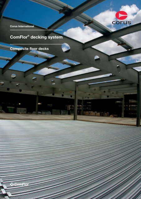
ComFlor ® <strong>decking</strong> <strong>system</strong><br />
Composite floor decks
Introduction<br />
Introduction<br />
Corus is one of the world’s leading<br />
steel suppliers, formed in 1999 by the<br />
merger of British <strong>Steel</strong> and Koninklijke<br />
Hoogovens. Combining international<br />
expertise with local customer service,<br />
the Corus brand represents quality<br />
and strength, providing innovative<br />
solutions to a wide variety of sectors<br />
worldwide. Corus became a subsidiary<br />
of <strong>Tata</strong> <strong>Steel</strong> in April 2007, leading to<br />
the creation of the world’s fifth largest<br />
steel producer. With a combined<br />
presence in 50 countries, <strong>Tata</strong> <strong>Steel</strong><br />
including Corus has 84,000 employees<br />
across six continents and a pro forma<br />
crude steel production of 27 million<br />
tonnes in 2007. The combined turnover<br />
of Corus and <strong>Tata</strong> <strong>Steel</strong> stood at<br />
US$24.8 billion in 2006.<br />
Corus International is the specialist<br />
supply chain management business<br />
unit with annual sales of 8 million tonnes<br />
of steel and a worldwide network of<br />
offices. We are continually expanding<br />
our reach and evaluating new markets<br />
for which a presence would bring local<br />
advantage. Our scope of supply<br />
extends across the full range of steel<br />
products, but our commercial teams<br />
specialise through retaining sectorspecific<br />
focus. Within this model, our<br />
teams have also developed relationships<br />
with third-party sources in order to offer<br />
a more flexible solution. According to<br />
our ISO 9001:2000 quality <strong>system</strong>, we<br />
only procure from companies with<br />
audited quality <strong>system</strong>s. In addition,<br />
we have stockholding facilities in North<br />
America, Europe, the Middle East and<br />
the Far East.<br />
Our deep decks span between beams<br />
with typical unpropped spans extending<br />
to 6 metres and propped spans to<br />
9 metres. The deck is contained within<br />
the beam depth, which provides a very<br />
shallow floor zone. The shape of the<br />
deck profiles allow for service<br />
integration and the whole <strong>system</strong><br />
provides inherent fire resistance.<br />
The overall service we provide covers<br />
design and detailing advice and supply<br />
of <strong>decking</strong> <strong>system</strong>s coupled with<br />
logistical, technical, finance and<br />
documentation support. As such,<br />
Corus International is in an excellent<br />
position to offer tailored <strong>decking</strong><br />
solutions to projects around the world,<br />
as proven by a long and successful<br />
track record of supplying these products<br />
to customers globally.<br />
Corus has in-house <strong>decking</strong> production<br />
facilities in the UK, UAE, India and<br />
New Zealand, through which we can<br />
offer either shallow or deep decks.<br />
The ComFlor range is arguably the<br />
most efficient choice of profile currently<br />
available anywhere in the world.<br />
Our shallow decks are suitable for<br />
conventional composite construction<br />
where the deck is placed onto the top<br />
flange of the steel support beam and<br />
each ComFlor profile offers particular<br />
application benefits.<br />
It is by combining our expertise and<br />
services innovatively and effectively,<br />
that we are able to offer our customers<br />
a complete solution, whatever the<br />
project requirements, wherever in the<br />
world. We provide the flexibility and<br />
dynamism of Corus International, whilst<br />
retaining our position within Corus as a<br />
respected partner. This gives a unique<br />
dual strength to our operations,<br />
supported by our ability to source<br />
materials in established and emerging<br />
markets across the globe.<br />
02
Introduction<br />
Corus International network<br />
A comprehensive steel supply service delivered<br />
throughout our worldwide network.<br />
ComFlor production sites<br />
Tewkesbury, UK – Produces CF46, CF51, CF60, CF80 and CF210<br />
Jebel Ali, UAE – Produces CF46, CF51 and CF80<br />
Auckland, New Zealand – Produces CF60, CF80 and CF210<br />
Mumbai, India – Produces CF60 and CF80<br />
03
ComFlor 46<br />
ComFlor 46<br />
Shallow composite profile<br />
Typical unpropped span 2.6m – 3.3m<br />
ComFlor 46, first introduced in 1985, is a simple<br />
trapezoidal composite deck with a strong and reliable<br />
shear bond performance. The profile is economic and<br />
nestable, reducing transport and handling costs.<br />
• Nestable<br />
The ultra efficient nesting capability<br />
of ComFlor 46 reduces the transport<br />
volume of the product. This fact<br />
combined with the simplicity of<br />
ComFlor 46 means it is an ideal<br />
solution worldwide.<br />
• Easy service suspension<br />
Ceilings and lightweight services can<br />
easily be attached to the punched<br />
hangar tabs, which can be included<br />
with ComFlor 46. These must be<br />
specified at time of order.<br />
• Low concrete usage<br />
The trapezoidal shape profile of<br />
ComFlor 46 reduces the volume of<br />
concrete used, with resultant savings<br />
in structural and foundation costs.<br />
04
ComFlor 46 design information<br />
ComFlor 46<br />
ComFlor 46 composite slab – volume and weight<br />
Weight of concrete (kN/m 2 )<br />
Concrete<br />
Slab depth volume Normal weight concrete Lightweight concrete<br />
(mm) (m 3 /m 2 ) Wet Dry Wet Dry<br />
110 0.091 2.14 2.10 1.69 1.60<br />
115 0.096 2.26 2.21 1.79 1.69<br />
120 0.101 2.38 2.33 1.88 1.78<br />
130 0.111 2.61 2.56 2.07 1.96<br />
140 0.121 2.85 2.79 2.25 2.13<br />
145 0.126 2.96 2.90 2.35 2.22<br />
150 0.131 3.08 3.02 2.44 2.31<br />
180 0.161 3.79 3.71 3.00 2.84<br />
200 0.181 4.26 4.17 3.37 3.19<br />
240 0.221 5.20 5.09 4.12 3.90<br />
Volume and weight table notes<br />
1. Deck and beam deflection (i.e. ponding)<br />
is not allowed for in the table.<br />
2. Deck and mesh weight is not included<br />
in the weight of concrete figures.<br />
3. Density of concrete is taken as:<br />
Normal weight (wet) 2400 kg/m 3<br />
Normal weight (dry) 2350 kg/m 3<br />
Lightweight (wet) 1900 kg/m 3<br />
Lightweight (dry) 1800 kg/m 3<br />
Section properties (per metre width)<br />
Nominal Design Height to Moment of Ultimate moment capacity<br />
thickness thickness Profile weight Area of steel neutral axis inertia (kNm/m)<br />
(mm) (mm) (kN/m 2 ) (mm 2 /m) (mm) (cm 4 /m) Sagging Hogging<br />
0.90 0.86 0.09 1137 20.38 41.50 4.63 4.67<br />
1.20 1.16 0.13 1534 20.44 53.00 5.99 6.23<br />
Span table – Normal weight concrete<br />
Maximum span (m)<br />
Deck thickness (mm)<br />
Props Span Fire Slab Mesh 0.9 1.2<br />
rating depth Total applied load (kN/m 2 )<br />
(mm) 3.5 5.0 10.0 3.5 5.0 10.0<br />
No temporary props<br />
Single span slab<br />
and deck<br />
Double span slab<br />
and deck<br />
1 hr 120 A193 2.4 2.4 2.4 2.8 2.8 2.6<br />
1.5 hrs 130 A193 2.4 2.4 2.7 2.7 2.7 2.3<br />
145 A252 2.3 2.4 2.2 2.6 2.6 2.2<br />
2 hrs 200 A393 2.0 2.0 2.0 2.3 2.3 2.3<br />
240 A393 1.9 1.9 1.9 2.2 2.2 2.2<br />
1 hr 130 A193 2.7 2.7 2.7 3.2 3.2 3.1<br />
1.5 hrs 130 A193 2.6 2.6 2.6 3.1 3.1 2.7<br />
145 A252 2.5 2.5 2.5 2.9 2.9 2.6<br />
2 hrs 200 A393 2.2 2.2 2.2 2.5 2.5 2.5<br />
240 A393 2.0 2.0 2.0 2.3 2.3 2.3<br />
Please refer to<br />
page 20 for span<br />
table parameters.<br />
Design notes<br />
Deck material<br />
Corus Galvatite, hot dip zinc coated steel<br />
EN 10326-S280GD+Z275 or equivalent.<br />
Guaranteed minimum yield stress 280N/mm 2 .<br />
Minimum zinc coating mass 275g/m 2 total<br />
both sides.<br />
Anti-crack mesh<br />
BS 5950: Part 4 currently recommends that<br />
anticrack mesh should comprise 0.1% of slab<br />
area. The Eurocode 4 recommendation is that<br />
anticrack mesh should comprise 0.2% of slab<br />
area for unpropped spans and 0.4% of slab<br />
area for propped spans. Where forklift truck<br />
(or other similar concentrated loading) is<br />
expected 0.5% minimum percentage<br />
reinforcement should be used over the<br />
supports and 2% elsewhere to control<br />
cracking. For further information refer to SCI<br />
AD150. Mesh top cover must be a minimum<br />
of 15mm, and a maximum of 30mm. Mesh<br />
laps are to be 300mm for A142 mesh and<br />
400mm for A193, A252 and A393 mesh.<br />
Fire<br />
For details of the performance of composite<br />
slabs comprising ComFlor 46 <strong>decking</strong> in<br />
simplified design cases or for full fire<br />
engineering, refer to the ComFlor software.<br />
Technical services<br />
Corus International offers a comprehensive<br />
advisory service on design of composite<br />
flooring, which is available to all specifiers<br />
and users. Should queries arise which are<br />
not covered by this literature or by the<br />
ComFlor software, please contact us.<br />
Details of full design, load spans and<br />
profile performance can be found by using<br />
the ComFlor software CD. Your free copy<br />
can be found on the inside back cover of<br />
this publication.<br />
05
ComFlor 51<br />
ComFlor 51<br />
Shallow composite profile<br />
Typical unpropped span 2.5m – 3.6m<br />
ComFlor 51 is a traditional dovetail re-entrant composite<br />
floor deck. This profile provides an excellent mechanical<br />
key into the concrete slab, offering a strong shear bond<br />
performance, which is augmented by cross stiffeners<br />
located in the profile trough. ComFlor 51 presents a<br />
virtually flat soffit and a relatively thin slab which is<br />
required to meet fire design requirements.<br />
• Shear studs<br />
The wide trough of ComFlor 51<br />
permits a flexible and efficient<br />
placement of shear studs.<br />
• Fire performance of the<br />
composite beams<br />
Even for two hours fire rating, the top<br />
flange of the steel beam does not<br />
require fire protection, when used with<br />
ComFlor 51 composite deck.<br />
• Under floor services<br />
Services are easy to attach to<br />
ComFlor 51, with the ribs presenting<br />
a dovetailed recessed groove in the<br />
concrete slab at 152.5mm centres.<br />
This provides the perfect connection<br />
for service hangars via a wedge nut<br />
or similar type device.<br />
• Fire performance of the slab<br />
The dovetail presents a very small<br />
opening and contributes little to the<br />
transfer of heat through the slab in the<br />
event of fire. Thus a lesser slab depth<br />
is needed for fire design purposes.<br />
• FibreFlor<br />
ComFlor 51 is fully tested with the<br />
FibreFlor <strong>system</strong> to provide all the<br />
benefits of a mesh-free solution.<br />
Please refer to pages 36 and 37 for<br />
details.<br />
06
ComFlor 51 design information<br />
ComFlor 51<br />
ComFlor 51 composite slab – volume and weight<br />
Weight of concrete (kN/m 2 )<br />
Concrete<br />
Slab depth volume Normal weight concrete Lightweight concrete<br />
(mm) (m 3 /m 2 ) Wet Dry Wet Dry<br />
101 0.092 2.16 2.12 1.71 1.62<br />
105 0.096 2.26 2.21 1.79 1.69<br />
110 0.101 2.37 2.32 1.88 1.78<br />
115 0.106 2.49 2.44 1.97 1.87<br />
120 0.111 2.61 2.55 2.07 1.96<br />
125 0.116 2.73 2.67 2.16 2.04<br />
130 0.121 2.84 2.78 2.25 2.13<br />
150 0.141 3.32 3.25 2.62 2.49<br />
200 0.191 4.49 4.40 3.56 3.37<br />
240 0.231 5.43 5.32 4.30 4.08<br />
Volume and weight table notes<br />
1. Deck and beam deflection (i.e. ponding)<br />
is not allowed for in the table.<br />
2. Deck and mesh weight is not included<br />
in the weight of concrete figures.<br />
3. Density of concrete is taken as:<br />
Normal weight (wet) 2400 kg/m 3<br />
Normal weight (dry) 2350 kg/m 3<br />
Lightweight (wet) 1900 kg/m 3<br />
Lightweight (dry) 1800 kg/m 3<br />
Section properties (per metre width)<br />
Nominal Design Height to Moment of Ultimate moment capacity<br />
thickness thickness Profile weight Area of steel neutral axis inertia (kNm/m)<br />
(mm) (mm) (kN/m 2 ) (mm 2 /m) (mm) (cm 4 /m) Sagging Hogging<br />
0.90 0.86 0.13 1579 16.74 55.70 5.69 6.99<br />
1.00 0.96 0.14 1759 16.73 62.10 6.34 7.93<br />
1.10 1.06 0.16 1938 16.73 68.50 7.00 8.88<br />
1.20 1.16 0.17 2118 16.72 74.90 7.65 9.81<br />
Span table – Normal weight concrete<br />
Maximum span (m)<br />
Deck thickness (mm)<br />
Props Span Fire Slab Mesh 0.9 1.2<br />
rating depth Total applied load (kN/m 2 )<br />
(mm) 3.5 5.0 10.0 3.5 5.0 10.0<br />
No temporary props<br />
Single span slab<br />
and deck<br />
Double span slab<br />
and deck<br />
1 hr 101 A142 2.8 2.8 2.5 3.2 3.2 2.8<br />
1.5 hrs 110 A142 2.7 2.7 2.2 3.1 3.0 2.4<br />
125 A193 2.6 2.5 2.0 2.9 2.6 2.1<br />
2 hrs 200 A393 2.2 2.2 2.2 2.6 2.6 2.6<br />
240 A393 2.1 2.1 2.1 2.4 2.4 2.4<br />
1 hr 101 A142 3.2 3.2 2.6 3.7 3.7 3.0<br />
1.5 hrs 110 A142 3.2 3.2 2.4 3.6 3.4 2.7<br />
125 A193 3.1 3.0 2.3 3.4 3.2 2.5<br />
2 hrs 200 A393 2.6 2.6 2.6 3.0 3.0 3.0<br />
240 A393 2.4 2.4 2.4 2.8 2.8 2.8<br />
Please refer to<br />
page 20 for span<br />
table parameters.<br />
Design notes<br />
Deck material<br />
Corus Galvatite, hot dip zinc coated steel<br />
EN 10326-S350GD+Z275 or equivalent.<br />
Guaranteed minimum yield stress 350N/mm 2 .<br />
Minimum zinc coating mass 275g/m 2 total<br />
both sides.<br />
Anti-crack mesh<br />
BS 5950: Part 4 currently recommends that<br />
anticrack mesh should comprise 0.1% of<br />
slab area. The Eurocode 4 recommendation<br />
is that anticrack mesh should comprise 0.2%<br />
of slab area for unpropped spans and 0.4%<br />
of slab area for propped spans. Where forklift<br />
truck (or other similar concentrated loading) is<br />
expected 0.5% minimum percentage<br />
reinforcement should be used over the<br />
supports and 2% elsewhere to control<br />
cracking. For further information refer to SCI<br />
AD150. Mesh top cover must be a minimum<br />
of 15mm, and a maximum of 30mm. Mesh<br />
laps are to be 300mm for A142 mesh and<br />
400mm for A193, A252 and A393 mesh.<br />
Fire<br />
For details of the performance of composite<br />
slabs comprising ComFlor 51 <strong>decking</strong> in<br />
simplified design cases or for full fire<br />
engineering, refer to the ComFlor software.<br />
Technical services<br />
Corus International offers a comprehensive<br />
advisory service on design of composite<br />
flooring, which is available to all specifiers<br />
and users. Should queries arise which are not<br />
covered by this literature or by the ComFlor<br />
software, please contact us.<br />
Details of full design, load spans and<br />
profile performance can be found by using<br />
the ComFlor software CD. Your free copy<br />
can be found on the inside back cover of<br />
this publication.<br />
07
ComFlor 60<br />
ComFlor 60 shown with<br />
FibreFlor reinforced concrete.<br />
ComFlor 60<br />
Shallow composite profile<br />
Typical unpropped span 3.0m – 4.4m<br />
Taking the 60 profile concept to a<br />
new dimension.<br />
Increased span: grade 350 steel<br />
combined with optimised finite element<br />
analysed profile design, gives<br />
exceptional unpropped span capability<br />
for a 60 profile.<br />
Optimum stud position: the profile<br />
design guarantees centrally placed<br />
shear studs.<br />
Coated soffit: ComFlor 60 is available<br />
with an optional 25-micron flexible<br />
polyester coating to the underside, ideal<br />
for use in car parks.<br />
Low concrete usage: the profile<br />
allows a reduced concrete volume<br />
for any slab depth delivering very<br />
competitive construction costs.<br />
Lighter sheets: the cover width of<br />
ComFlor 60 is 600mm, to reduce sheet<br />
weight and improve handling.<br />
Corus International has combined the<br />
experience of twenty years in composite<br />
floor profile design into the engineering<br />
of this state-of-the-art profile. The new<br />
roll forming technology pioneered with<br />
ComFlor 80 allows coated soffit<br />
composite flooring to be made available<br />
now on the 60, thus widening the range<br />
of choice for car parks and other similar<br />
applications.<br />
The profile is specifically designed to<br />
enhance shear stud interaction, with<br />
the trough stiffeners and side lap<br />
making it impossible to put the studs in<br />
the wrong place. The cover width has<br />
been deliberately limited to 600mm to<br />
reduce sheet weight and provide a<br />
major health and safety benefit in<br />
manual handling. Optimised profile<br />
design combined with 350 grade steel<br />
provides exceptional spans combined<br />
with reduced concrete usage.<br />
‘Closed ends’<br />
• FibreFlor<br />
ComFlor 60 is fully tested with the<br />
FibreFlor <strong>system</strong> to provide all the<br />
benefits of a mesh-free solution.<br />
Please refer to pages 36 and 37<br />
for details.<br />
08
ComFlor 60 design information<br />
ComFlor 60<br />
ComFlor 60 composite slab – volume and weight<br />
Weight of concrete (kN/m 2 )<br />
Concrete<br />
Slab depth volume Normal weight concrete Lightweight concrete<br />
(mm) (m 3 /m 2 ) Wet Dry Wet Dry<br />
120 0.089 2.09 2.04 1.65 1.57<br />
130 0.099 2.32 2.28 1.84 1.74<br />
140 0.109 2.56 2.51 2.03 1.92<br />
150 0.119 2.79 2.74 2.21 2.10<br />
160 0.129 3.03 2.97 2.40 2.27<br />
170 0.139 3.27 3.20 2.59 2.45<br />
180 0.149 3.50 3.43 2.77 2.63<br />
190 0.157 3.69 3.62 2.92 2.77<br />
200 0.167 3.93 3.85 3.11 2.95<br />
250 0.217 5.11 5.00 4.04 3.83<br />
Volume and weight table notes<br />
1. Deck and beam deflection (i.e. ponding)<br />
is not allowed for in the table.<br />
2. Deck and mesh weight is not included in<br />
the weight of concrete figures.<br />
3. Density of concrete is taken as:<br />
Normal weight wet 2400 kg/m 2<br />
Normal weight dry 2350 kg/m 2<br />
Light weight wet 1900 kg/m 2<br />
Light weight dry 1800 kg/m 2<br />
Section properties (per metre width)<br />
Nominal Design Height to Moment of Ultimate moment capacity<br />
thickness thickness Profile weight Area of steel neutral axis inertia (kNm/m)<br />
(mm) (mm) (kN/m 2 ) (mm 2 /m) (mm) (cm 4 /m) Sagging Hogging<br />
0.90 0.86 0.103 1276 29.6 92.77 9.30 7.50<br />
1.00 0.96 0.114 1424 30.5 106.15 11.27 9.36<br />
1.10 1.06 0.125 1572 31.2 119.53 13.24 11.21<br />
1.20 1.16 0.137 1721 31.7 132.91 15.21 13.07<br />
Span table – Normal weight concrete<br />
Maximum span (m)<br />
Deck thickness (mm)<br />
Props Span Fire Slab Mesh 0.9 1.2<br />
rating depth Total applied load (kN/m 2 )<br />
(mm) 3.5 5.0 10.0 3.5 5.0 10.0<br />
No temporary props<br />
Single span slab<br />
and deck<br />
Double span slab<br />
and deck<br />
130 A142 3.5 3.2 2.3 3.9 3.4 2.5<br />
1 hr 130 A252 3.5 3.5 2.6 3.9 3.9 2.8<br />
1.5 hrs<br />
2 hrs<br />
160 A252 3.2 3.2 2.9 3.6 3.6 3.1<br />
140 A193 3.4 2.9 2.1 3.7 3.1 2.3<br />
170 A252 3.1 3.1 2.4 3.5 3.5 2.6<br />
150 A193 2.9 2.5 1.9 3.0 2.6 1.9<br />
180 A252 3.1 3.0 2.1 3.5 3.0 2.2<br />
130 A142 3.6 3.6 2.7 4.5 3.9 2.9<br />
1 hr 130 A252 3.6 3.6 3.2 4.5 4.5 3.3<br />
1.5 hrs<br />
2 hrs<br />
160 A252 3.3 3.3 3.3 4.2 4.2 3.8<br />
140 A193 3.5 3.5 2.6 4.1 3.6 2.7<br />
170 A252 3.2 3.2 3.2 4.1 4.1 3.3<br />
150 A193 3.4 3.0 2.3 3.5 3.1 2.4<br />
180 A252 3.1 3.1 2.8 4.1 3.9 2.9<br />
Please refer to<br />
page 20 for span<br />
table parameters.<br />
Design notes<br />
Deck material<br />
Corus Galvatite, hot dip zinc coated steel<br />
EN10326-S350GD+Z275 or equivalent.<br />
Guaranteed minimum yield stress 350N/mm 2 .<br />
Minimum zinc coating mass 275g/m 2 total<br />
both sides.<br />
Anti-crack mesh<br />
BS 5950: Part 4 currently recommends that<br />
anti-crack mesh should comprise 0.1% of<br />
slab area. The Eurocode 4 recommendation<br />
is that anti-crack mesh should comprise<br />
0.2% of slab area for unpropped spans and<br />
0.4% of slab area for propped spans. Where<br />
forklift truck (or other similar concentrated<br />
loading) is expected 0.5% minimum<br />
percentage reinforcement should be used<br />
over the supports and 2% elsewhere to<br />
control cracking. For further information refer<br />
to SCI AD150. Mesh top cover must be a<br />
minimum of 15mm, and a maximum of<br />
30mm. Mesh laps are to be 300mm for<br />
A142 mesh and 400mm for A193, A252<br />
and A393 mesh.<br />
Fire<br />
For details of the performance of composite<br />
slabs comprising ComFlor 60 <strong>decking</strong> in<br />
simplified design cases or for full fire<br />
engineering, refer to the ComFlor software.<br />
Technical services<br />
Corus International offers a comprehensive<br />
advisory service on design of composite<br />
flooring, which is available to all specifiers<br />
and users. Should queries arise which are not<br />
covered by this literature or by the ComFlor<br />
software, please contact us.<br />
Details of full design, load spans and<br />
profile performance can be found by using<br />
the ComFlor software CD. Your free copy<br />
can be found on the inside back cover of<br />
this publication.<br />
09
ComFlor 80<br />
ComFlor 80<br />
Shallow composite profile<br />
Typical unpropped span 3.8m – 5.1m<br />
ComFlor 80 is the next generation of profiled steel composite decks; it is the only 80mm<br />
profile utilising the higher grade 450 steel and available in Colorcoat ® .<br />
The large corner curvature detail provides a very efficient profile. In conjunction with the<br />
higher grade of steel, it ensures typical unpropped spans of 4.4m simply supported and in<br />
the continuous condition, spans of 5.1m can be achieved.<br />
The large spans achievable mean less structural steel is used and this provides savings in the<br />
overall construction cost, which also offers more scope to architects and engineers in the<br />
design process.<br />
The innovative profile design<br />
provides real benefits<br />
• Central stud placement provides<br />
superb composite action between the<br />
beam and concrete due to the stud<br />
being positioned exactly in the centre<br />
of the trough. This ensures the correct<br />
concrete cover to the stud and<br />
therefore, the full design capacity of<br />
the stud is developed. The central<br />
location of the stud also reduces onsite<br />
checking by ensuring that the<br />
stud has been positioned correctly.<br />
• Ideal for car parks<br />
ComFlor 80 is available with an<br />
optional 25-micron flexible polyester<br />
coating to the underside, for use in<br />
car parks.<br />
• The use of high grade 450 steel, plus<br />
the highly efficient CF80 profile<br />
design, provides long span capability.<br />
• Excellent concrete usage means<br />
that ComFlor 80 is very economical<br />
compared to other similar decks.<br />
• Improved manual handling<br />
The cover width of ComFlor 80 is<br />
600mm, to reduce sheet weight and<br />
improve handling.<br />
• FibreFlor<br />
ComFlor 80 is fully tested with the<br />
FibreFlor <strong>system</strong> to provide all the<br />
benefits of a mesh-free solution.<br />
Please refer to pages 36 and 37<br />
for details.<br />
10
ComFlor 80 design information<br />
ComFlor 80<br />
180 300 120<br />
15<br />
80<br />
95<br />
ComFlor 80 composite slab – volume and weight<br />
15.8<br />
35 50 35<br />
90 180<br />
120<br />
17.2<br />
Weight of concrete (kN/m 2 )<br />
Concrete<br />
Slab depth volume Normal weight concrete Lightweight concrete<br />
(mm) (m 3 /m 2 ) Wet Dry Wet Dry<br />
130 0.086 2.03 1.99 1.61 1.53<br />
140 0.096 2.27 2.22 1.80 1.70<br />
150 0.106 2.51 2.45 1.98 1.88<br />
160 0.116 2.74 2.68 2.17 2.06<br />
170 0.126 2.98 2.91 2.36 2.23<br />
180 0.136 3.21 3.14 2.54 2.41<br />
190 0.146 3.45 3.38 2.73 2.59<br />
200 0.156 3.68 3.61 2.92 2.76<br />
250 0.206 4.86 4.76 3.85 3.64<br />
Cover width 600mm<br />
Setting out point (s.o.p.)<br />
Volume and weight table notes<br />
1. Deck and beam deflection (i.e. ponding)<br />
is not allowed for in the table.<br />
2. Deck and mesh weight is not included<br />
in the weight of concrete figures.<br />
3. Density of concrete is taken as:<br />
Normal weight (wet) 2400 kg/m 3<br />
Normal weight (dry) 2350 kg/m 3<br />
Lightweight (wet) 1900 kg/m 3<br />
Lightweight (dry) 1800 kg/m 3<br />
Section properties (per metre width)<br />
Nominal Design Height to Moment of Ultimate moment capacity<br />
thickness thickness Profile weight Area of steel neutral axis inertia (kNm/m)<br />
(mm) (mm) (kN/m 2 ) (mm 2 /m) (mm) (cm 4 /m) Sagging Hogging<br />
0.90 0.86 0.12 1387 47.6 185 15.4 12.5<br />
1.20 1.16 0.15 1871 47.6 245 22.2 18.5<br />
Span table – Normal weight concrete<br />
Maximum span (m)<br />
with no extra reinforcements<br />
Deck thickness (mm)<br />
Props Span Fire Slab Mesh 0.9 1.2<br />
rating depth Total applied load (kN/m 2 )<br />
(mm) 3.5 5.0 10.0 3.5 5.0 10.0<br />
No temporary props<br />
Single span slab<br />
and deck<br />
Double span slab<br />
and deck<br />
1 hr<br />
1.5 hrs<br />
2 hrs<br />
1 hr<br />
1.5 hrs<br />
2 hrs<br />
140 A252 4.2 3.6 2.5 4.5 3.8 2.7<br />
170 A252 4.0 4.0 2.8 4.2 4.2 3.0<br />
150 A393 4.1 3.6 2.5 4.4 3.7 2.6<br />
180 A393 3.9 3.9 2.7 4.2 4.2 2.9<br />
160 A393 4.0 3.1 2.3 3.8 3.1 2.3<br />
190 A393 3.8 3.6 2.4 4.1 3.5 2.5<br />
140 A252 4.4 4.4 3.2 5.2 4.6 3.4<br />
170 A252 3.9 3.9 3.6 4.8 4.8 3.8<br />
150 A393 4.2 4.0 3.0 4.8 4.1 3.1<br />
180 A393 3.8 3.8 3.5 4.7 4.7 3.6<br />
160 A393 4.1 3.6 2.7 4.2 3.6 2.8<br />
190 A393 3.7 3.7 3.1 4.7 4.2 3.2<br />
Please refer to<br />
page 20 for span<br />
table parameters.<br />
Design notes<br />
Deck material<br />
Corus Galvatite, hot dip zinc coated steel<br />
EN 10326-S450GD+Z275 or equivalent.<br />
Guaranteed minimum yield stress up to<br />
450N/mm 2 . Minimum zinc coating mass<br />
275g/m 2 total both sides.<br />
Anti-crack mesh<br />
BS 5950: Part 4 currently recommends that<br />
anticrack mesh should comprise 0.1% of slab<br />
area. The Eurocode 4 recommendation is that<br />
anticrack mesh should comprise 0.2% of<br />
slab area for unpropped spans and 0.4%<br />
of slab area for propped spans. Where forklift<br />
truck (or other similar concentrated loading) is<br />
expected 0.5% minimum percentage<br />
reinforcement should be used over the<br />
supports and 2% elsewhere to control<br />
cracking. For further information refer to SCI<br />
AD150. Mesh top cover must be a minimum<br />
of 15mm and a maximum of 30mm. Mesh<br />
laps are to be 300mm for A142 mesh and<br />
400mm for A193, A252 and A393 mesh.<br />
Fire<br />
For details of the performance of composite<br />
slabs comprising ComFlor 80 <strong>decking</strong> in<br />
simplified design cases or for full fire<br />
engineering, refer to the ComFlor software.<br />
Technical services<br />
Corus International offers a comprehensive<br />
advisory service on design of composite<br />
flooring, which is available to all specifiers<br />
and users. Should queries arise which are not<br />
covered by this literature or by the ComFlor<br />
software, please contact us.<br />
Details of full design, load spans and<br />
profile performance can be found by using<br />
the ComFlor software CD. Your free copy<br />
can be found on the inside back cover of<br />
this publication.<br />
11
Shallow composite floor decks Design information<br />
Design information<br />
Composite floor <strong>decking</strong> design is generally dictated by the construction stage condition, the load and span required for<br />
service and the fire resistance required for the slab. The deck design is also influenced by the composite beam design.<br />
Design parameters<br />
• Fire rating – dictates minimum slab<br />
depth.<br />
• Concrete type – also dictates minimum<br />
slab depth and influences unpropped<br />
deck span.<br />
• Deck span – (unpropped) usually<br />
dictates general beam spacing.<br />
• Slab span – (propped deck) dictates<br />
maximum beam spacing.<br />
Two stage design<br />
All Composite Floors must be considered<br />
in two stages.<br />
• Wet concrete and construction load –<br />
carried by deck alone.<br />
• Cured concrete – carried by composite<br />
slab.<br />
General design aims<br />
Generally designers prefer to reduce<br />
the requirement to provide temporary<br />
propping and so the span and slab depth<br />
required governs the deck selection. Fire<br />
requirements usually dictate slab depth.<br />
For most applications, the imposed load<br />
on the slab will not limit the design.<br />
Quick reference and full design<br />
The combination of this manual and<br />
ComFlor software makes both quick<br />
reference and full design easy. Indicative<br />
design may be carried out from the printed<br />
tables, however the software greatly<br />
increases the scope available to the<br />
Design Engineer and allows the engineer<br />
to print a full set of calculations.<br />
British standards and Eurocodes<br />
The Software user is offered a choice to<br />
design to either BS5950 Parts 4 and 3 or<br />
to Eurocode 4. The quick reference tables<br />
are designed to BS5950 Part 4, with the<br />
important exception of the mesh<br />
recommendations.<br />
Anti-crack mesh<br />
FibreFlor can be used to replace anti<br />
crack mesh. Where mesh is used, BS5950:<br />
Part 4 recommends that it comprises<br />
0.1% of slab area. The Eurocode 4<br />
recommendation is that anti-crack mesh<br />
should comprise 0.2% of slab area for<br />
unpropped spans and 0.4% of slab area<br />
for propped spans.<br />
In slabs subject to line loads, the mesh<br />
should comprise 0.4% of the crosssectional<br />
area of the concrete topping,<br />
propped and unpropped.<br />
These limits ensure adequate crack control<br />
in visually exposed applications (0.5mm<br />
maximum crack width). The mesh<br />
reinforcement should be positioned at a<br />
maximum of 30mm from the top surface.<br />
Elsewhere, 0.1% reinforcement may be<br />
used to distribute local loads on the slab<br />
(or 0.2% to EC4).<br />
Mesh laps are to be 300mm for A142<br />
mesh and 400mm for A193, A252 and<br />
A393.<br />
Forklift trucks<br />
Where forklift truck (or other similar<br />
concentrated loading) is expected 0.5%<br />
minimum percentage reinforcement should<br />
be used over the supports and 0.2%<br />
elsewhere to control cracking. For further<br />
information refer to SCI AD150.<br />
Exposed floors<br />
Composite floors are usually covered by<br />
finishes, flooring or a computer floor; and<br />
because cracking is not visible, light top<br />
reinforcement is adequate, typically 0.1%<br />
of the gross cross sectional area. However<br />
where the composite slab is to be left<br />
uncovered, e.g. for power trowelled floor<br />
finishes, cracking, particularly over the<br />
beams, may not be adequately controlled<br />
by the light mesh usually provided. The<br />
cracking has no structural significance, but<br />
the appearance of it, and the possibility of<br />
the crack edge breakdown under traffic,<br />
may be perceived as a problem. In this<br />
case, refer to Concrete Society publication.<br />
‘Cracking In Composite Concrete /<br />
Corrugated Metal Decking Floors Slabs’<br />
which provides valid mesh sizing and<br />
detailing for specific crack width control.<br />
Where forklifts are to be used also refer to<br />
<strong>Steel</strong> Construction Institute advisory note<br />
‘AD 150, Composite Floors – Wheel Loads<br />
from Forklifts’. Both publications are<br />
available from our Technical Department.<br />
Reduced mesh<br />
1.2m 1.2m 1.2m 1.2m<br />
Support Support Support<br />
Beam Beam Beam<br />
Diagram showing full mesh area over supports<br />
Where EC4 mesh rules are used, as<br />
recommended by <strong>Steel</strong> Construction<br />
Institute and Corus, the full stipulated<br />
mesh applies to the slab 1.2m either side<br />
of every support. Outside of this, i.e. in<br />
the midspan area, the mesh area may be<br />
halved (to 0.2% for propped and 0.1%<br />
for unpropped construction), provided<br />
there are no concentrated loads, openings<br />
etc. to be considered. Also the reduced<br />
midspan mesh must be checked for<br />
adequacy under fire, for the rating<br />
required.<br />
Bar reinforcement<br />
The Axis Distance of bar reinforcement<br />
defines the distance from the bottom of<br />
the ribs to the centre of the bar, which has<br />
a minimum value of 25mm, and a<br />
maximum value of the profile height.<br />
Where used, bar reinforcement is placed<br />
at one bar per profile trough.<br />
Transverse reinforcement<br />
Corus composite floor decks contribute<br />
to transverse reinforcement of the<br />
composite beam, provided that the <strong>decking</strong><br />
is either continuous across the top flange of<br />
the steel beam or alternatively that it is<br />
welded to the steel beam by stud shear<br />
connectors. For further information refer to<br />
BS5950:Part 3: Section 3.1.Clause 5.6.4.<br />
12
Design information Shallow composite floor decks<br />
Concrete choice<br />
Lightweight concrete (LWC) uses<br />
artificially produced aggregate such as<br />
expanded pulverised fuel ash pellets.<br />
LWC leads to considerable advantages in<br />
improved fire performance, reduced slab<br />
depth, longer unpropped spans and<br />
reduced dead load. However, LWC is not<br />
readily available in some parts of the<br />
country. Normal weight concrete uses a<br />
natural aggregate and is widely available.<br />
The strength of the concrete must meet<br />
the requirements for strength for the<br />
composite slab and shall not be less than<br />
25N/mm 2 for LWC or 30N/mm 2 for NWC.<br />
Similarly, the maximum value of concrete<br />
strength shall not be taken as greater than<br />
40N/mm 2 for LWC or 50N/mm 2 for NWC.<br />
The modular ratio defines the ratio of the<br />
elastic modulus of steel to concrete, as<br />
modified for creep in the concrete.<br />
In design to BS5950 and BS8110, the<br />
cube strength is used (in N/mm 2 ). In design<br />
to EC3, the cylinder strength is used (in<br />
N/mm 2 ). The concrete grade (C30/37)<br />
defines the (cylinder/cube strength) to EC3.<br />
Fire design methods<br />
There are two requirements for fire design:<br />
• Bending resistance in fire conditions.<br />
• Minimum slab depth for insulation<br />
purposes.<br />
The capacity of the composite slab in fire<br />
may be calculated using either the Simple<br />
Method or the Fire Engineering Method.<br />
The simple method will be the most<br />
economic. The fire engineering method<br />
should be used for design to Eurocodes.<br />
The Simple Method: The Simple Method<br />
may be used for simply supported decks<br />
or for decks continuous over one or more<br />
internal supports. The capacity<br />
assessment in fire is based on a single or<br />
double layer of standard mesh. Any bar<br />
reinforcement is ignored.<br />
The Fire Engineering Method: The Fire<br />
Engineering Method is of general<br />
application. The capacity assessment in<br />
fire is based on a single or double layer of<br />
standard mesh at the top and one bar in<br />
each concrete rib. For the shallow decks,<br />
the program assumes the bar is positioned<br />
just below the top of the steel deck.<br />
account the deflection should not<br />
exceed the span/130 or 30mm overall.<br />
The quick reference tables do take<br />
ponding into account, if deflection exceeds<br />
Ds/10, or Le/180, and thus use span/130<br />
or 30mm as a deflection limit.<br />
It is recommended that the prop width<br />
should not be less than 100mm otherwise<br />
the deck may mark slightly at prop lines.<br />
Vibration<br />
The dynamic sensitivity of the composite<br />
slab should be checked in accordance<br />
with the <strong>Steel</strong> Construction Institute<br />
publication P076: Design guide on the<br />
vibration of floors. The natural frequency<br />
is calculated using the selfweight of the<br />
slab, ceiling and services, screed and<br />
10% imposed loads, representing the<br />
permanent loads and the floor. In the<br />
absence of more appropriate information,<br />
the natural frequency of the composite<br />
slab should not exceed 5Hz for normal<br />
office, industrial or domestic usage.<br />
Conversely, for dance floor type<br />
applications or for floors supporting<br />
sensitive machinery, the limit may need<br />
to be set higher.<br />
Concrete density<br />
Density kg/m3<br />
Wet Dry Modular ratio<br />
LWC 1900 1800 15<br />
NWC 2400 2350 10<br />
In the absence of more precise<br />
information, the following assumptions<br />
may be made: The wet density is used in<br />
the design of the profiled steel sheets and<br />
the dry density, in the design of the<br />
composite slab.<br />
Fire design<br />
Fire insulation<br />
The fire insulation requirements of BS<br />
5950: Part 8, must be satisfied and are<br />
taken into account in the tables and design<br />
software.<br />
Span/depth ratio<br />
Slab span to depth ratio is limited to a<br />
maximum of 30 for lightweight concrete<br />
and 35 for normal weight concrete.<br />
Shear connectors in fire situation<br />
If shear connectors are provided, any<br />
catenary forces transferred from the slab<br />
to the support beams can be ignored<br />
within the fire resistance periods quoted.<br />
Shallow composite floors generally use<br />
the simplified fire design method which<br />
utilises the anti-crack mesh as fire<br />
reinforcement. Increased load span<br />
capability under fire may be realised by<br />
including bar reinforcement and using<br />
the fire engineering method of design.<br />
Deflection limits<br />
Deflection Limits would normally be<br />
agreed with the client. In the absence<br />
of more appropriate information, the<br />
following limits should be adopted:<br />
Construction stage<br />
Le/130 (but not greater than 30mm)<br />
Imposed load deflection<br />
Le/350 (but not greater than 20mm)<br />
Total load deflection<br />
Le/250 (but not greater than 30mm)<br />
According to BS5950 Part 4, ponding,<br />
resulting from the deflection of the <strong>decking</strong><br />
is only taken into account if the<br />
construction stage deflection exceeds<br />
Ds/10. Le is the effective span of the deck<br />
and Ds is the slab overall depth (excluding<br />
non-structural screeds).<br />
The deflection under construction load<br />
should not exceed the span/180 or 20mm<br />
overall, whichever is the lesser, when the<br />
ponding of the concrete slab is not taken<br />
into account. Where ponding is taken into<br />
For design to the Eurocodes, the loads<br />
considered for the vibration check are<br />
increased using the psi-factor for imposed<br />
loads (typically 0.5). The natural frequency<br />
limit may be reduced to 4Hz, because of<br />
this higher load, used in the calculation.<br />
Loads and load arrangement<br />
Loading information would normally<br />
be agreed with the clients. Reference<br />
should also be made to BS 6399 and<br />
to EC1.<br />
Factored loads are considered at the<br />
ultimate limit state and unfactored<br />
loads at the serviceability limit state.<br />
Unfactored loads are also considered<br />
in fire conditions.<br />
Partial factors are taken from BS5950,<br />
EC3 and EC4.<br />
Loads considered at the construction<br />
stage consist of the slab self weight and<br />
the basic construction load. The basic<br />
construction load is taken as 1.5 kN/m 2<br />
or 4.5/Lp (whichever is greater), where<br />
Lp is the span of the profiled steel sheets<br />
between effective supports in metres.<br />
For multi span unpropped construction,<br />
the basic construction load of 1.5 kN/m 2<br />
is considered over the one span only.<br />
13
Shallow composite floor decks Design information<br />
On other spans, the construction load<br />
considered is half this value (i.e. 0.75<br />
kN/m 2 ). Construction loads are considered<br />
as imposed loads for this check.<br />
Loads considered at the normal service<br />
stage consist of the slab self weight,<br />
superimposed dead loads and imposed<br />
loads.<br />
Openings<br />
Openings can be accommodated readily<br />
in composite slabs, by boxing out prior to<br />
pouring concrete and cutting out the deck<br />
after concrete has cured, see sitework<br />
section on page 22. The design of<br />
openings depends on their size:<br />
Small<br />
Openings up to 300mm square – do not<br />
normally require additional reinforcement.<br />
Medium<br />
Openings between 300mm and 700mm<br />
square – normally require additional<br />
reinforcement to be placed in the slab.<br />
This is also the case if the openings are<br />
placed close together.<br />
Slab design around openings<br />
It may be assumed that an effective<br />
<strong>system</strong> of ‘beam strips’ span the perimeter<br />
of the opening. The effective breadth of the<br />
beam strips should be taken as d o /2,<br />
where d o is the width of the opening in the<br />
direction transverse to the <strong>decking</strong> ribs.<br />
Only the concrete above the ribs is<br />
effective. The transverse beam strips are<br />
assumed to be simply supported, and<br />
span a distance of 1.5 d o . The longitudinal<br />
beam strips are designed to resist the load<br />
from the transverse beam strips, in<br />
addition to their own proportion of the<br />
loading.<br />
Reinforcement<br />
Extra reinforcement is provided within the<br />
‘beam strips’ to suit the applied loading.<br />
This reinforcement often takes the form of<br />
bars placed in the troughs of the <strong>decking</strong>.<br />
Additional transverse or diagonal bars may<br />
be used to improve load transfer around<br />
the opening.<br />
Section A-A<br />
Mesh<br />
Extra bars in troughs<br />
Section B-B<br />
Extra bars over deck<br />
End bars in slab (over the deck)<br />
Large<br />
Openings greater than 700mm square –<br />
should be trimmed with additional<br />
permanent steelwork back to the support<br />
beams.<br />
Opening<br />
Opening rules<br />
Where W = width of opening across the<br />
span of the deck.<br />
1. The distance between the opening and<br />
unsupported edge must be greater than<br />
500mm or W, whichever is the greater.<br />
2. Openings must not be closer together<br />
than 1.5W (of the largest opening) or<br />
300mm, whichever is the greater. If they<br />
are closer they must be considered as<br />
one opening.<br />
3. Not more than 1 ⁄4 width of any bay<br />
is to be removed by openings.<br />
4. Not more than 1 ⁄4 width of deck span<br />
is to be removed by openings.<br />
d o<br />
/2<br />
Extra bars in troughs<br />
Centre line<br />
of floor beam<br />
Transverse reinforced<br />
concrete beam strip<br />
Centre line<br />
of floor beam<br />
Where these rules are not satisfied, the<br />
openings must be fully trimmed with<br />
support steelwork.<br />
d o<br />
d o<br />
/2 d o<br />
/2<br />
d o<br />
/2<br />
Deck span<br />
Effective span of<br />
transverse beam<br />
strips = 1.5d o<br />
If the opening falls within the usual<br />
effective breadth of concrete flange of any<br />
composite beams (typically span/8 each<br />
side of the beam centre line), the beam<br />
resistance should be checked assuming an<br />
appropriately reduced effective breadth<br />
of slab.<br />
Load paths and beam strips around medium<br />
to large openings<br />
Longitudinal reinforced<br />
concrete beam strips<br />
14
Design information Shallow composite floor decks<br />
Design of shear studs<br />
Composite beam design.<br />
Savings in beam weight of up to 50% can<br />
be achieved when the composite slab is<br />
effectively anchored to the steel beam.<br />
The slab will then act as a compression<br />
flange to the beam.<br />
Force applied to shear stud<br />
The methods of connection between slab<br />
and beam is generally by means of through<br />
deck welding of 19mm diameter shear<br />
studs of varying height, which are fixed to<br />
the beam after the <strong>decking</strong> has been laid.<br />
Shear stud specification<br />
19mm x 95mm studs are used with CF46,<br />
CF51 and CF60.<br />
19mm x 125mm studs are used with CF80.<br />
Crushing<br />
Top flange of beam<br />
Centre welding of shear-connectors<br />
Crushing<br />
Force applied to slab<br />
Headed studs<br />
When deck profile ribs are running<br />
perpendicular to the steel beam i.e.<br />
compositely connected to the composite<br />
slab, the capacity of headed studs should<br />
be taken as their capacity in a solid slab<br />
but multiplied by the reduction factor “k”.<br />
The calculation method for “k” differs<br />
between BS5950 Part 3 and Eurocode 4.<br />
Through deck welded stud reduction factor k – see note 1 below<br />
BS5950 Part 3 Centre placed, Unfavourably placed<br />
favourably placed or<br />
studs<br />
offset placed studs (2)<br />
1 stud/rib 2 studs/rib 1 stud/rib 2 studs/rib<br />
CF46 and CF51 1.00 0.80 1.00 0.80<br />
CF60 1.00 0.80 N/A* N/A*<br />
CF80 (125mm stud) 0.80 0.56 N/A* N/A*<br />
*CF60 and 80 profile ensures centre placed studs.<br />
Suitability of decks<br />
Shear studs cannot be placed on profile<br />
stiffeners, however with CF60 and CF80<br />
the position of the stiffeners and side lap<br />
allows central placement of studs.<br />
Non-welded shear connectors<br />
Hilti shear connectors may be used.<br />
Refer to Hilti for further information.<br />
EC4 Ribs perpendicular Ribs parallel<br />
(transverse) to beam<br />
to beam<br />
1 stud/rib 2 studs /rib<br />
CF46 and CF51 – 1mm or less 0.85 0.70 1.00<br />
CF60 – 1mm or less 0.85 0.70 0.85<br />
CF46 and CF51 1.00 0.80 1.00<br />
CF46 and CF51 – greater than 1mm 1.00 0.80 1.00<br />
CF80 0.66 0.46 0.56<br />
Design guide<br />
The <strong>Steel</strong> Construction Institute/Metal<br />
Cladding and Roofing Manufacturers<br />
Association P300 “Composite Slabs<br />
and Beams using <strong>Steel</strong> Decking: Best<br />
Practice for Design and Construction”<br />
is recommended by Corus for further<br />
reference.<br />
Central studs<br />
*76mm = 4d for 19mm studs<br />
Note 1<br />
At the time of print, the stud reduction factors<br />
in BS5950 Part 3 and in the National Annex<br />
for EC4 are subject to review, please check<br />
with our Technical Department to see if these<br />
figures are still current.<br />
*76mm<br />
min<br />
25mm min, edge of stud to edge of beam<br />
15
Shallow composite floor decks Construction details<br />
Construction details<br />
Plan view of typical floor layout<br />
Deck notation<br />
Edge trim<br />
dimensions<br />
Y<br />
X<br />
Edge trim reference<br />
F75<br />
X<br />
Tie<br />
member<br />
dimensions<br />
Indicates cut plate<br />
245 mm wide<br />
F75<br />
Beam<br />
member<br />
centreline<br />
C P<br />
245<br />
Distance (mm)<br />
from centreline<br />
of tie member<br />
to Setting Out<br />
Point (s.o.p.)<br />
of <strong>decking</strong><br />
first sheet.<br />
94<br />
6-1000<br />
2107<br />
C<br />
D<br />
Indicates cut deck<br />
Indicates bay<br />
which requires<br />
temporary<br />
propping.<br />
F75<br />
X = distance (mm)<br />
from centreline of<br />
beam to edge of<br />
slab (parallel to<br />
deck span)<br />
Y = distance (mm)<br />
from centreline of tie<br />
member to edge of<br />
slab (perpendicular<br />
to deck span)<br />
Floor<br />
level<br />
Number<br />
of sheets<br />
Phase<br />
Decking<br />
lengths<br />
6-1000<br />
2107<br />
Bundle<br />
number<br />
Span of<br />
<strong>decking</strong><br />
Y<br />
F75<br />
Typical side detail<br />
Tie member centres<br />
Y<br />
<strong>Steel</strong> stud<br />
Edge trim<br />
For cantilevers over 150mm, additional<br />
reinforcement is required.<br />
CF 80<br />
Floor <strong>decking</strong><br />
25 min<br />
Universal beam<br />
Cantilever dimension<br />
Typical side detail<br />
Unsupported edge detail<br />
Tie member centres<br />
X<br />
100mm<br />
minimum<br />
<strong>Steel</strong> stud<br />
Edge trim<br />
Edge trim<br />
Restraint<br />
Restraint<br />
strap<br />
strap<br />
at 600mm<br />
centres<br />
Timber<br />
Reinforcement<br />
bearer<br />
as specified<br />
Temporary<br />
CF 80<br />
25 min<br />
See typical plan for<br />
prop<br />
Floor <strong>decking</strong><br />
dimension ‘X’, & ‘Y’<br />
Universal beam<br />
16
Construction details Shallow composite floor decks<br />
Typical end cantilever<br />
Butt joint<br />
X<br />
Beam centres<br />
25 min<br />
<strong>Steel</strong> stud if<br />
applicable<br />
Edge of flange<br />
to side of stud<br />
50 min<br />
Edge trim fixed to<br />
<strong>decking</strong> sheet<br />
Restraint straps at<br />
600mm centres<br />
Dimension ‘X’ required<br />
Maximum cantilever<br />
500mm, greater<br />
cantilevers require<br />
temporary props and<br />
additional reinforcement<br />
or steelwork brackets<br />
connected to the<br />
Universal beam<br />
Universal beam<br />
CF 80<br />
Floor <strong>decking</strong><br />
to extend to<br />
edge trim<br />
Universal beam<br />
CF 80<br />
Floor <strong>decking</strong><br />
Studs in pairs or<br />
staggered where a<br />
butt joint occurs<br />
Deck to be butt<br />
jointed over<br />
centreline of beam<br />
End detail<br />
Step in floor<br />
X<br />
Beam centres<br />
Restraint strap<br />
<strong>Steel</strong> stud<br />
Edge trim fixed<br />
to align with<br />
edge of beam<br />
CF 80 Floor <strong>decking</strong><br />
Edge trim<br />
CF 80 Floor <strong>decking</strong><br />
to centreline of beam<br />
to centreline of beam<br />
Cantilever<br />
dimension<br />
Universal beam<br />
25mm min.<br />
For cantilevers over<br />
150mm additional<br />
reinforcement is<br />
required.<br />
RSA to be wide enough<br />
to provide sufficient<br />
bearing and allow fixing<br />
of deck without fouling<br />
top flange of beam<br />
above<br />
Universal beam<br />
CF 80<br />
Floor <strong>decking</strong><br />
with a minimum<br />
50mm bearing<br />
17
Shallow composite floor decks Construction details<br />
End detail alternative 1<br />
End detail alternative 2<br />
X<br />
Beam centres<br />
X<br />
Beam centres<br />
Stud on centreline<br />
of beam<br />
Restraint strap<br />
<strong>Steel</strong> stud<br />
Edge trim<br />
CF51 Floor <strong>decking</strong><br />
to extend to edge trim<br />
Edge trim<br />
CF51 Floor <strong>decking</strong><br />
to centreline of beam<br />
Restraint<br />
strap at<br />
600mm<br />
centres<br />
Cantilever<br />
dimension<br />
20mm min.<br />
For Cantilevers over<br />
150mm additional<br />
reinforcement is required.<br />
Universal beam<br />
Universal beam<br />
Side cantilever with stub bracket<br />
Typical edge with plate<br />
Dimension required<br />
Y<br />
Beam centres<br />
Restraint<br />
Edge trim<br />
<strong>Steel</strong> stud<br />
CF 80<br />
Floor<br />
<strong>decking</strong><br />
strap<br />
Edge trim<br />
CF 80 Floor <strong>decking</strong><br />
<strong>Steel</strong> stub as<br />
designed by<br />
engineer<br />
50mm<br />
min<br />
Closure plate in 2mm<br />
flat steel strip to suit<br />
remainder of floor area<br />
to a maximum of<br />
245mm. Reference<br />
CP245 (plate width)<br />
Universal beam<br />
Universal beam<br />
18
Construction details Shallow composite floor decks<br />
Beam at perimeter wall<br />
Typical wall end detail<br />
25<br />
X<br />
Beam centres<br />
Overall wall dimension<br />
Restraint strap<br />
Stud on centreline of beam<br />
CE100 edge<br />
trim leaving<br />
room for<br />
25mm<br />
Korkpak joint<br />
CF51 Floor <strong>decking</strong><br />
to extend to edge<br />
trim<br />
Edge trim to align with<br />
edge of wall<br />
CF80 Floor <strong>decking</strong> with<br />
75mm (minimum) bearing<br />
onto wall<br />
Perimeter<br />
wall<br />
100mm wall shown here<br />
Universal beam<br />
Typical wall side detail<br />
Deck inside of wall detail<br />
Wall outer dimensions<br />
<strong>Steel</strong> or wall to wall<br />
10mm min<br />
CF80 Floor <strong>decking</strong> with<br />
75mm (minimum) bearing<br />
onto wall<br />
CF80 Floor <strong>decking</strong> with<br />
50mm (minimum) bearing<br />
onto steel angle<br />
Masonry fixing to wall at<br />
500mm c/c<br />
Edge trim to align with<br />
edge of wall<br />
RSA, RSC or universal beam<br />
100mm wall shown here<br />
Perimeter wall<br />
19
Shallow composite floor decks Sitework<br />
Sitework<br />
Deck fixing<br />
Immediately after laying, the deck must<br />
be fixed through its trough to the top of<br />
the supporting structure. Powder<br />
actuated pins or self-drilling screws are<br />
used. Side lap fixings are required at<br />
1000mm centres for CF46, CF60 and<br />
CF80. Where shear studs are being<br />
used, the deck requires two fixings per<br />
sheet per support at sheet ends and<br />
one fixing per sheet at intermediate<br />
supports.<br />
Fixing information for shallow <strong>decking</strong><br />
To steel<br />
Heavy duty powder actuated fixings – Hilti ENP2 X-ENP-19 L15 nail/Spit<br />
SBR14 or equivalent. For temporary fixing (i.e. where weld through shear<br />
studs are to be used) – Hilti PINDAK16*<br />
Self-drilling screws. To steel up to 11mm thick – SFS SD14 – 5.5 x 32 /<br />
EJOT HS 38 or equivalent. To steel up to 17mm thick SFS TDC-T-6.3<br />
x 38 or equivalent<br />
To masonry Pre drill hole – use self tapping fixing suitable for masonry/concrete –<br />
or concrete<br />
SFS TB-T range/EJOT 4H32 or equivalent<br />
To side laps<br />
Self drilling stitching screw typically SFS SL range/EJOT SF25 or<br />
or closures etc.<br />
equivalent<br />
Where shear studs are not employed,<br />
the deck must be fixed as follows:<br />
Wind loading*<br />
Where temporary fixings, such as<br />
PINDAK, are used, wind loading should<br />
be checked, especially on exposed<br />
sites.<br />
Fixing spacings<br />
ComFlor 46 ComFlor 51<br />
and ComFlor 60 ComFlor 80<br />
End fixing<br />
3 per sheet<br />
(2 per sheet when 2 per sheet<br />
using shear studs)<br />
Intermediate<br />
2 per sheet<br />
supports (1 per sheet when 1 per sheet<br />
using shear studs)<br />
Side laps 1 fixing at 1000mm c/c (not required for CF 51)<br />
Side fixing onto support<br />
1 fixing at 600mm c/c<br />
Parameters assumed for shallow<br />
deck quick reference span tables<br />
Mesh<br />
See notes on profile pages.<br />
Spans<br />
Measured centre to centre of supports.<br />
Deck<br />
Standard deck material specification.<br />
Bearing width<br />
The width of the support is assumed to<br />
be 200mm.<br />
Prop width<br />
Assumed to be 100mm.<br />
Deflection<br />
Construction stage L/130 or 30mm<br />
(ponding has been taken into account).<br />
Deflection<br />
Composite stage L/350.<br />
Concrete grade<br />
The concrete is assumed to be grade 35<br />
with a maximum aggregate size of<br />
20mm. The wet weight of concrete is<br />
taken to be normal weight 2400kg/m 3 .<br />
The modular ratio is 10 for normal<br />
weight.<br />
Construction load<br />
No allowance is made for heaping.<br />
Fire<br />
The fire engineering method (FE)<br />
has been used to calculate the<br />
reinforcement needed to achieve the<br />
fire rating. The minimum slab thickness<br />
indicated in each table for each fire<br />
rating satisfies the fire insulation<br />
requirements of BS 5950: Part 8.<br />
Span/depth ratio<br />
This is limited to 30 for lightweight<br />
concrete and 35 for normal weight<br />
concrete.<br />
20
Sitework Shallow composite floor decks<br />
Bearing requirements<br />
End bearing and shared bearing (minimum)<br />
Continuous bearing (minimum)<br />
50mm 50mm 75mm<br />
<strong>Steel</strong> section<br />
<strong>Steel</strong> section<br />
70mm<br />
70mm<br />
100mm<br />
Masonry<br />
Masonry<br />
Edge trim<br />
This is used to retain the wet concrete<br />
to the correct level at the <strong>decking</strong><br />
perimeters. It is fixed to the supports<br />
in the same manner as the deck and the<br />
top is restrained by straps at 600mm<br />
centres, which are fixed to the top of<br />
the deck profile, by steel pop rivets or<br />
self-drilling screws.<br />
Edge trim selector<br />
Edge<br />
Maximum cantilever (mm)<br />
trim Galv. <strong>Steel</strong> Edge Trim Thickness (mm)<br />
depth 0.9 1.2 1.6 2.0<br />
130 100 125 160 195<br />
150 0 115 150 185<br />
200 x 100 130 160<br />
250 x 0 100 135<br />
300 x x 0 100<br />
350 x x x 0<br />
x – not recommended<br />
21
Shallow composite floor decks Sitework<br />
Shear connectors<br />
Most commonly used shear connectors<br />
are 19mm diameter headed studs,<br />
which are welded to the support beam<br />
through the deck, a process carried out<br />
by specialist stud welding contractors.<br />
Site conditions must be suitable for<br />
welding and bend tests carried out as<br />
appropriate.<br />
The spacing and position of the shear<br />
connectors is important and must be<br />
defined by the design engineer on the<br />
deck set out drawings.<br />
Minimum Spacing: The minimum centreto<br />
spacing of stud shear connectors<br />
should be 5d along the beam and 4d<br />
between adjacent studs, where d is the<br />
nominal shank diameter. Where rows of<br />
studs are staggered, the minimum<br />
transverse spacing of longitudinal lines<br />
of studs should be 3d. The shear stud<br />
should not be closer than 20mm to the<br />
edge of the beam. Further guidance<br />
on shear studs for designers and<br />
installers may be found in The <strong>Steel</strong><br />
Construction Institution publications:<br />
P300 Composite Slabs and Beams<br />
Using <strong>Steel</strong> Decking: Best Practice for<br />
Design and Construction, P055 Design<br />
of Composite Slabs and Beams with<br />
<strong>Steel</strong> Decking.<br />
Mesh placement<br />
FibreFlor can be used in place of anti<br />
crack mesh, which eliminates all mesh<br />
position issues. However if reinforcing<br />
mesh is used, it is positioned towards<br />
the top of the slab. The top cover to the<br />
reinforcement mesh should be a<br />
minimum of 15mm and a maximum of<br />
30mm. Support stools are required to<br />
maintain the correct mesh height. The<br />
mesh must be lapped by 300mm for<br />
A142 and A193 mesh, and by 400mm<br />
for A252 and A393 mesh.<br />
Casting concrete<br />
Before the concrete is poured, the<br />
<strong>decking</strong> must be cleared of all dirt and<br />
grease, which could adversely influence<br />
the performance of the hardened slab.<br />
The oil left on the <strong>decking</strong> from the roll<br />
forming process does not have to be<br />
removed. Concrete should be poured<br />
evenly, working in the direction of span.<br />
Care should be taken to avoid heaping<br />
of concrete in any area during the<br />
casting sequence. Construction and day<br />
joints should occur over a support<br />
beam, preferably also at a deck joint.<br />
Ceilings and services hanger <strong>system</strong>s<br />
The dovetail shaped re-entrant rib on<br />
ComFlor 51 and the 15mm high raised<br />
minidovetail re-entrant stiffener on<br />
the ComFlor 60 and ComFlor 80 profiles<br />
allow for the quick and easy suspension<br />
of ceiling and services, using either of<br />
the two following suspension <strong>system</strong>s.<br />
ComFlor 51<br />
ComFlor 80<br />
(a) Threaded wedge nut fixings<br />
Wedges are dovetail shaped steel<br />
blocks, which are threaded to take<br />
metric bolts or threaded rods. The<br />
wedge nut hanger <strong>system</strong> is installed<br />
after the concrete of the composite slab<br />
has been poured and is hardened.<br />
Installation<br />
For installation of the <strong>system</strong>, wedge<br />
nuts are inserted into the raised reentrants<br />
of the profile before being<br />
rotated 90 degrees, after which the<br />
dovetail shaped wedge nuts will lock<br />
into the dovetail re-entrants under<br />
vertical loading. Finally, the bolts or<br />
threaded rods are finger tightened up<br />
to the roof of the re-entrants and<br />
mechanically tightened.<br />
(b) GTD-clip hangar fixings<br />
GTD-clip hangar fixings are cold formed<br />
thin steel hangers with circular openings<br />
in the soffit to take metric bolts,<br />
threaded rods or further pipe clamp<br />
hangers. The <strong>system</strong> is installed after<br />
the composite slab has been poured<br />
and the concrete is sufficiently<br />
hardened.<br />
Installation<br />
To install the GTD-clips, the two dovetail<br />
shaped ends are compressed by hand<br />
and inserted into the dovetail re-entrant<br />
of the profile, before being rotated 90<br />
degrees. One then lets go of the two<br />
ends and the clip will snap into position<br />
and is tightly connected. Finally, bolts,<br />
threaded rods or pipe clamps are<br />
connected into the soffit opening of the<br />
GTD-clip.<br />
Loadbearing capacities<br />
Thread Maximum<br />
System size static working<br />
load (kg)<br />
Wedge Nut 4 100<br />
6 100<br />
8 100<br />
GTD – Clip 6 90 8 90<br />
10 90<br />
GTD – Clip and N/A 45<br />
Pipe Clamp<br />
A minimum safety factor of 4 has been applied<br />
to the safe working load capacities<br />
22
Sitework construction details<br />
Sitework construction details Shallow composite floor decks<br />
Openings<br />
Openings greater than 300mm must<br />
be designed by the engineer, with extra<br />
reinforcement placed around the<br />
opening. Openings up to 700mm can<br />
be accommodated readily in composite<br />
slabs, by boxing out prior to pouring<br />
concrete and cutting out the deck after<br />
concrete has cured. Larger openings<br />
require support trimming steel, which<br />
must be installed prior to the <strong>decking</strong>.<br />
The <strong>decking</strong> is cut away immediately<br />
and the opening edges are then treated<br />
like any other perimeter with edge trim.<br />
Timber shutter<br />
Dense polystyrene block<br />
Note: do not cut the opening in the<br />
steel deck prior to concreting, or<br />
before the concrete has cured.<br />
Temporary support using an<br />
‘Acrow’ type prop<br />
Temporary supports<br />
The safe design and installation of<br />
temporary props is the responsibility of<br />
the main contractor or designated subcontractor.<br />
Where temporary supports<br />
are required by the design, these must<br />
provide continuous support to the<br />
profiled sheeting. Spreader beams<br />
(timbers) are used, supported by<br />
temporary props at one metre centres.<br />
[a] The timbers and props must be of<br />
adequate strength and construction<br />
[b] The temporary supports are placed<br />
at midspan or at other suitable centres<br />
if more supports per span are required.<br />
Please contact our Technical Department<br />
[c] The spreader beams or timbers are<br />
to provide a minimum bearing width of<br />
100mm. The spreaders must not deflect<br />
more than 10mm and should be placed<br />
narrow edge up, see diagram.<br />
[d] The propping structure is not to be<br />
removed until the concrete has reached<br />
at least 70% of its characteristic<br />
strength. The horizontal bearer timbers<br />
must be at least 100mm wide and<br />
should be propped at no more than 1m<br />
centres. Sometimes the specification<br />
may call for 150mm wide bearers, as<br />
determined by the structural engineer<br />
or concreting contractor.<br />
Props should be stable without relying<br />
on friction with the deck for laterial<br />
stability. The end props in a row should<br />
be self supporting, and braced to the<br />
internal props.<br />
Percussive drilling<br />
Percussive drilling into composite<br />
concrete slabs is not recommended,<br />
however small scale rotary hammer drills<br />
are considered to be satisfactory.<br />
Temporary props<br />
Timber bearer guide (shallow decks)<br />
All to be min. 100mm wide<br />
Slab depth (mm) Bearer depth (mm)<br />
up to 120 150<br />
130 – 160 200<br />
170 – 200 250<br />
23
ComFlor 210<br />
ComFlor 210<br />
Deep composite profile<br />
Typical unpropped span<br />
4.5m – 6.0m<br />
The original SlimFlor long span steel deck, ComFlor 210<br />
has the capability to span up to 6 metres in unpropped<br />
construction. Suitable for use in Corus Slimdek ®<br />
construction, which offers minimal structural depth,<br />
fast construction and many other benefits.<br />
• With cross and longitudinal stiffeners,<br />
CF210 is structurally efficient and<br />
offers excellent composite action with<br />
the concrete.<br />
• Simple single bar reinforcement in<br />
each trough, combined with anticrack<br />
mesh near the top of the<br />
concrete slab gives the composite<br />
slab superb structural strength and<br />
fire properties.<br />
• The nestable profile shape reduces<br />
transport and handling costs.<br />
• Up to 2 hours fire rating with<br />
unprotected soffit.<br />
24
ComFlor 210 design information<br />
ComFlor 210<br />
ComFlor 210 composite slab – volume and weight<br />
Weight of concrete (kN/m 2 )<br />
Concrete<br />
Slab depth volume Normal weight concrete Lightweight concrete<br />
(mm) (m 3 /m 2 ) Wet Dry Wet Dry<br />
270 0.100 2.36 2.31 1.87 1.77<br />
280 0.110 2.60 2.54 2.05 1.95<br />
290 0.120 2.83 2.77 2.24 2.12<br />
300 0.130 3.07 3.00 2.43 2.30<br />
305 0.135 3.18 3.12 2.52 2.39<br />
310 0.140 3.30 3.23 2.61 2.48<br />
330 0.160 3.77 3.69 2.99 2.83<br />
350 0.180 4.24 4.16 3.36 3.18<br />
375 0.205 4.83 4.73 3.83 3.62<br />
400 0.230 5.42 5.31 4.29 4.07<br />
Volume and weight table notes<br />
1. Deck and beam deflection (i.e. ponding)<br />
is not allowed for in the table.<br />
2. Deck and mesh weight is not included<br />
in the weight of concrete figures.<br />
3. Density of concrete is taken as:<br />
Normal weight (wet) 2400 kg/m 3<br />
Normal weight (dry) 2350 kg/m 3<br />
Lightweight (wet) 1900 kg/m 3<br />
Lightweight (dry) 1800 kg/m 3<br />
Section properties (per metre width)<br />
Nominal Design Height to Moment of Ultimate moment capacity<br />
thickness thickness Profile weight Area of steel neutral axis inertia (kNm/m)<br />
(mm) (mm) (kN/m 2 ) (mm 2 /m) (mm) (cm 4 /m) Sagging Hogging<br />
1.25 1.21 0.16 2009 95.00 816.00 23.20 23.20<br />
Span table – Normal weight concrete<br />
Maximum span (m)<br />
Total applied load (kN/m 2 )<br />
Props Span Fire Slab Mesh 3.5kN/m 2 5kN/m 2 10kN/m 2<br />
rating depth Bar size (mm)<br />
(mm) 12 16 20 25 12 16 20 25 12 16 20 25<br />
No temporary props<br />
Single span slab<br />
280 A142 4.8 5.4 5.4 5.4 4.3 5.4 5.4 5.4 3.4 4.5 5.4 5.4<br />
1 hr 300 A193 4.8 5.2 5.2 5.2 4.4 5.2 5.2 5.2 3.5 4.6 5.2 5.2<br />
350 A393 4.7 4.7 4.7 4.7 4.5 4.7 4.7 4.7 3.7 4.7 4.7 4.7<br />
290 A193 3.7 4.9 5.3 5.3 3.4 4.4 5.3 5.3 2.7 3.5 4.3 5.3<br />
1.5 hrs 300 A193 3.7 4.9 5.2 5.2 3.4 4.5 5.2 5.2 2.7 3.6 4.4 5.2<br />
350 A393 3.8 4.7 4.7 4.7 3.5 4.6 4.7 4.7 2.8 3.8 4.6 4.7<br />
305 A193 2.0 2.7 3.3 4.1 1.8 2.4 3.0 3.7 1.5 1.9 2.4 3.0<br />
2 hrs 350 A393 2.1 2.7 3.4 4.2 1.9 2.5 3.1 3.8 1.5 2.0 2.5 3.1<br />
Please refer to page 29 for span table<br />
parameters.<br />
400 A393 2.1 2.7 3.4 4.2 1.9 2.6 3.2 3.9 1.6 2.1 2.6 3.3<br />
Design notes<br />
Deck material<br />
Corus Galvatite, hot dip zinc coated steel<br />
EN 10326-S350GD+Z275 or equivalent.<br />
Guaranteed minimum yield stress 350N/mm 2 .<br />
Minimum zinc coating mass 275g/m 2 total<br />
both sides.<br />
Anti-crack mesh<br />
BS 5950: Part 4 currently recommends that<br />
anticrack mesh should comprise 0.1% of slab<br />
area. The Eurocode 4 recommendation is that<br />
anticrack mesh should comprise 0.2% of slab<br />
area for unpropped spans and 0.4% of slab<br />
area for propped spans. Where forklift truck<br />
(or other similar concentrated loading) is<br />
expected 0.5% minimum percentage<br />
reinforcement should be used over the<br />
supports and 2% elsewhere to control<br />
cracking.<br />
For further information refer to SCI AD150.<br />
Mesh top cover must be a minimum of<br />
15mm, and a maximum of 30mm. Mesh laps<br />
are to be 300mm for A142 mesh and 400mm<br />
for A193, A252 and A393 mesh.<br />
Technical services<br />
Corus International offers a comprehensive<br />
advisory service on design of composite<br />
flooring, which is available to all specifiers<br />
and users. Should queries arise which are not<br />
covered by this literature or by the ComFlor<br />
software, please contact us.<br />
Fire<br />
For details of the performance of composite<br />
slabs comprising ComFlor 210 <strong>decking</strong> in<br />
simplified design cases or for full fire<br />
engineering, refer to the ComFlor software.<br />
Bar reinforcement<br />
End anchorage for bar reinforcement. All<br />
cases require properly anchored L-bars at the<br />
supports, except for those indicated in yellow.<br />
Cases indicated in yellow may have straight<br />
bars, with an anchorage length of 70mm from<br />
the edge of the support. One bar is placed in<br />
each profile trough, the cover to deck soffit is<br />
assumed at 70mm.<br />
Details of full design, load spans and<br />
profile performance can be found by using<br />
the ComFlor software CD. Your free copy<br />
can be found on the inside back cover of<br />
this publication.<br />
25
Deep composite floor decks Design information<br />
Design information<br />
Deep Composite Floor Decks will be considered where longer span (4m plus) floor slabs are required.<br />
When combined with Corus Slimdek ® <strong>system</strong>, deep decks are designed to achieve a very shallow overall structural floor.<br />
Deep composite floor decks<br />
Our Deep Composite Floor Decks will<br />
be used in one of these applications:<br />
1 Corus Slimdek ® <strong>system</strong>.<br />
2 Long span composite concrete/steel<br />
floor deck in composite steel<br />
construction.<br />
3 Long span composite concrete/steel<br />
floor deck in masonry construction.<br />
The design considerations relating<br />
to the <strong>decking</strong> are similar for all these<br />
applications.<br />
Corus Slimdek ® <strong>system</strong><br />
This <strong>system</strong> comprises Asymmetric<br />
Slimflor ® Beams (ASB) and deep CF210<br />
<strong>decking</strong>.<br />
Asymmetric Slimflor ® Beam (ASB), which is a hot rolled section with a narrower top flange than<br />
bottom flange.<br />
The principle of Slimdek ® is that the<br />
steel deck (and thus the composite<br />
concrete slab) bears on the lower flange<br />
of the beam, thus containing the beam<br />
within the floor slab. Three different<br />
types of Slimflor ® beam are produced:<br />
Slimflor ® Fabricated Beam (SFB), which is a Universal Column section with a wide flange plate<br />
welded to its underside.<br />
Rectangular Hollow Slimflor ® Beam (RHSFB), which is a rectangular hollow section with a flange<br />
plate welded to its lower face (generally used for edge beams).<br />
26
Design information Deep composite floor decks<br />
Slimdek ® design procedure<br />
There are two distinct stages for which<br />
the elements of the Slimdek ® <strong>system</strong><br />
must be designed. The first is the<br />
construction stage, during which the<br />
beams and <strong>decking</strong> support the loads<br />
as non-composite sections. During the<br />
second stage the <strong>decking</strong> and concrete<br />
act together to form composite slabs, as<br />
do (generally) the ASBs and slab. SFBs<br />
and RHSFBs will act compositely if<br />
shear studs have been provided.<br />
The key design points are:<br />
• Consideration of the required spans<br />
will allow the depth of the beams to<br />
be determined.<br />
• Consideration of the required fire<br />
resistance will allow the depth of slab<br />
to be determined, as a function of the<br />
cover required for the beams and the<br />
<strong>decking</strong>.<br />
Having established these scheme<br />
design parameters, detailed design of<br />
the beams and slab can be undertaken.<br />
The following slab depths should be<br />
considered as typical:<br />
280 ASB sections – 290-320mm deep slab<br />
300 ASB sections – 315-340mm deep slab.<br />
These depths will provide adequate<br />
cover to the ASB for it to act<br />
compositely with the slab. For SFBs a<br />
greater range of slab depths may be<br />
considered for a given depth of beam;<br />
the slab depth requirement will depend<br />
on whether shear studs must be<br />
accommodated to make the SFB act<br />
compositely.<br />
Decking design<br />
In addition to considering the selfweight<br />
of the slab, the design of the<br />
deep <strong>decking</strong> should take into account<br />
temporary construction loads. These<br />
construction loads differ slightly from<br />
those that should be considered for<br />
shallow <strong>decking</strong>, because of the<br />
considerably greater spans that can be<br />
achieved with deep <strong>decking</strong>.<br />
Construction stage loading<br />
The 1.5 kN/m 2 construction load<br />
required by BS 5950-4 should only be<br />
applied over the middle 3m of the span,<br />
as shown below.<br />
A reduced load of 0.75 kN/m 2 (as<br />
specified in EC4) may be applied<br />
outside this region, as it would be overly<br />
conservative to apply the full load of<br />
1.5kN/m 2 over the entire span. The<br />
effect of concrete ponding should be<br />
taken into account (by increasing the<br />
self weight of the slab) if the deflection<br />
under self-weight alone exceeds the<br />
lesser of span/180 or 20mm.<br />
If temporary props are used to support<br />
the <strong>decking</strong> during construction, a<br />
construction load of 1.5 kN/m 2 should<br />
be considered as acting over the<br />
complete span (between permanent<br />
supports). Although a lower value might<br />
be justifiable over parts of the span, a<br />
constant load should be considered for<br />
design simplicity.<br />
Temporary propping (when required)<br />
The spacing of temporary props is<br />
governed by the ability of the <strong>decking</strong><br />
to resist combined bending and shear in<br />
the hogging (negative) moment regions<br />
over the lines of props.<br />
It is recommended that the spacing<br />
between the props should be relatively<br />
close, so that local loads do not cause<br />
damage to the <strong>decking</strong> (2.5m to 3.5m<br />
spacing depending on the slab weight).<br />
A 100mm wide timber bearer should<br />
be used to distribute the load at these<br />
points.<br />
End bearing<br />
The end bearing of the sheets should<br />
be specified as 50mm. The flange<br />
widths are such that this bearing can be<br />
achieved, whilst still allowing the sheets<br />
to be dropped vertically into position<br />
(i.e. without having to ‘thread’ them<br />
between the top and bottom flanges).<br />
Slimdek ® beam design<br />
The design of the beams in the Slimdek ®<br />
<strong>system</strong> is presented in The Corus<br />
Slimdek ® Manual and Design Software<br />
which is available from Corus<br />
Construction Centre +44 (0)1724<br />
405060. Further detailed design<br />
information is available in The <strong>Steel</strong><br />
Construction Institute publications: P300<br />
Composite Slabs and Beams Using<br />
<strong>Steel</strong> Decking: Best Practice for Design<br />
and Construction, P055 Design of<br />
Composite Slabs and Beams with <strong>Steel</strong><br />
Decking. Please see references section<br />
on page 38 for further information.<br />
Construction load<br />
1.5 kN/m 2 x 1.6<br />
Self weight x 1.4<br />
3m<br />
Clear span + 0.075m<br />
Reduced construction load<br />
0.75 kN/m 2 x 1.6<br />
27
Deep composite floor decks Design information<br />
Slab design<br />
The design of composite slabs using<br />
deep <strong>decking</strong> differs from that for<br />
shallow <strong>decking</strong> in the following ways:<br />
Placing bar reinforcement in the troughs<br />
of the <strong>decking</strong> increases the ultimate<br />
load resistance of the slab. The benefit<br />
of these bars is considered in both the<br />
‘normal’ and fire conditions.<br />
The slab depth may need to be chosen<br />
not only to satisfy the structural,<br />
durability and fire resistance<br />
requirements of the slab itself, but also<br />
to provide appropriate cover over ASB<br />
or Slimflor beams.<br />
The reinforcing bars in the troughs of the<br />
<strong>decking</strong> provide additional tensile area<br />
to that provided by the <strong>decking</strong>, and<br />
thus enhance the bending resistance of<br />
the composite slab.<br />
Bar diameters range from 8mm to<br />
32 mm, depending on the span and<br />
fire resistance requirements.<br />
Straight bars may be used to achieve<br />
60 minutes fire resistance (provided<br />
that shear stresses are low). In other<br />
cases, L bars should be used to<br />
provide sufficient end anchorage in<br />
fire conditions.<br />
Cracking<br />
It is normal for some cracking to occur<br />
in the slab over the beams. These<br />
cracks run parallel with the beams and<br />
are not detrimental to the structural<br />
behaviour of the slab. They may be<br />
controlled by mesh reinforcement<br />
provided across the tops of the beams.<br />
Guidance on the detailing of<br />
reinforcement to control cracking may<br />
be found in the Corus Slimdek ® manual.<br />
Additional reinforcement may be<br />
required to fulfil the following roles:<br />
• Transverse reinforcement adjacent to<br />
shear connectors.<br />
• U-bars at composite edge beams.<br />
• Additional crack control<br />
reinforcements<br />
• Strengthening around openings.<br />
• Strengthening at positions of<br />
concentrated loads.<br />
Fire resistance<br />
One of the principal considerations<br />
governing the choice of slab depth is<br />
the required fire resistance period.<br />
Minimum depths are given above as a<br />
function of the concrete type and fire<br />
resistance required and are based on<br />
insulation requirements.<br />
The Fire Engineering Method: The<br />
capacity assessment in fire is based<br />
on a single or double layer of standard<br />
mesh at the top and one bar in each<br />
concrete rib. For CF210 <strong>decking</strong>, the bar<br />
is placed at an axis distance, dependent<br />
on the fire resistance period. The axis<br />
distance must not be less than 70mm.<br />
To maximise fire resistance capacity the<br />
axis distance needs to be 70, 90 and<br />
120mm (from the soffit of the deck) for<br />
60, 90 and 120 minutes fire resistance,<br />
respectively. However where fire<br />
resistance is not the limiting factor it<br />
may be more effective for the axis<br />
distance to be at the minimum.<br />
Concrete thickness above deck<br />
Fire resistance NWC LWC<br />
60min 70mm 60mm<br />
90min 80mm 70mm<br />
120min 95mm 80mm<br />
Reduced mesh<br />
Where EC4 mesh rules are used, as<br />
recommended by The <strong>Steel</strong><br />
Construction Institute and Corus, the<br />
full stipulated mesh applies to the slab<br />
1.2m either side of every support.<br />
Outside of this, i.e. in the midspan area,<br />
the mesh area may be halved (to 0.2%<br />
for propped and 0.1% for unpropped<br />
construction), provided there are no<br />
concentrated loads, openings etc. to be<br />
considered. Also the reduced midspan<br />
mesh must be checked for adequacy<br />
under fire, for the rating required.<br />
1.2m 1.2m 1.2m 1.2m<br />
Support<br />
Mid span<br />
Concrete in<br />
compression<br />
Support Support Support<br />
Beam Beam Beam<br />
Vertical<br />
reaction<br />
Slip between<br />
deck and concrete<br />
Longitudinal<br />
shear bond<br />
1<br />
100mm<br />
Bar reinforcement<br />
ø<br />
12 ø<br />
25<br />
100mm<br />
50 ø<br />
Stress<br />
distribution<br />
Tension<br />
in <strong>decking</strong><br />
and bar<br />
reinforcement<br />
ø<br />
Diagram showing full mesh area over supports<br />
Vibration<br />
The dynamic sensitivity of the<br />
composite slab should be checked in<br />
accordance with the SCI publication<br />
P076: Design guide on the vibration of<br />
floors. The natural frequency is<br />
calculated using the self-weight of the<br />
slab, ceiling and services, screed and<br />
10% imposed loads, representing the<br />
permanent loads and the floor self<br />
weight.<br />
In the absence of more appropriate<br />
information, the natural frequency of the<br />
composite slab should not exceed 5Hz<br />
for normal office, industrial or domestic<br />
usage. For designs using CF210<br />
<strong>decking</strong>, this limit may be reduced to<br />
4Hz if the design has been carried out<br />
28
Design information Deep composite floor decks<br />
on the assumption of simple supports<br />
at the ends. Conversely, for dance floor<br />
type applications or for floors supporting<br />
sensitive machinery, the limit may need<br />
to be set higher.<br />
In the Slimdek <strong>system</strong>, consideration<br />
should be given to the <strong>system</strong> frequency<br />
of the floor as a whole if the natural<br />
frequency of the slab and/or the<br />
supporting beam is less than 5Hz.<br />
For design to the Eurocodes, the loads<br />
considered for the vibration check are<br />
increased using the psi-factor for<br />
imposed loads (typically 0.5). The<br />
natural frequency limit may be reduced<br />
to 4Hz, because of this higher load<br />
used in the calculation.<br />
Partial continuity<br />
Partial continuity for deep <strong>decking</strong>:<br />
Tests have shown that the CF210<br />
composite slabs supported on a steel<br />
beam and provided with adequately<br />
detailed continuity mesh reinforcement<br />
over the steel beam support exhibits a<br />
degree of continuity at the support.<br />
The beneficial effect of partial continuity<br />
at the supports may be taken into<br />
account by specifying CONTINUOUS in<br />
the Span Type field. When this option is<br />
specified, the following assumptions are<br />
made by the design software;<br />
• a 20% reduction in the deflections of<br />
the composite slab at the normal<br />
design stage.<br />
• a 30% reduction in the deflections<br />
when assessing the natural frequency<br />
of the slab. This is justified by the<br />
lower stress levels during vibration.<br />
• stresses in the composite slab in fire<br />
conditions are derived from a model<br />
which assumes full continuity at one<br />
end and a simple support at the other<br />
(i.e a propped cantilever condition).<br />
In this case, the amount of mesh<br />
reinforcement is increased to a minimum<br />
of 0.4% of the cross-sectional area of<br />
the concrete topping in order to develop<br />
sufficient continuity in the slab.<br />
Note that in all cases, partial continuity<br />
is ignored in assessing the capacity of<br />
the composite slab at the normal design<br />
stage.<br />
Openings in the slab<br />
Provision for vertical service openings<br />
within the floor slab will necessitate<br />
careful design and planning. The<br />
following summarises the options that<br />
are available to the designer:<br />
Openings up to 300mm x 300mm can<br />
be accommodated anywhere in the slab<br />
over a crest section of the deck,<br />
normally without needing additional<br />
reinforcement.<br />
Openings up to 400mm wide x 1000mm<br />
long may be taken through the crest of<br />
the deep <strong>decking</strong>. Additional<br />
reinforcement, which should be<br />
designed in accordance with BS 8110,<br />
may be required around the opening.<br />
Openings up to 1000mm wide x<br />
2000mm long may be accommodated<br />
by removing one rib (maximum) of the<br />
<strong>decking</strong>, fixing suitable edge trims and<br />
providing additional reinforcement to<br />
transfer forces from the discontinuous<br />
rib. The slab should be designed as a<br />
ribbed slab in accordance with BS 8110,<br />
with <strong>decking</strong> being used as permanent<br />
formwork. Guidance may be found in<br />
the Corus Slimdek Manual.<br />
Opening up to 1000mm<br />
Larger openings will generally require<br />
trimming by secondary beams.<br />
If an opening greater than 300mm x<br />
300mm lies within the effective width of<br />
slab adjacent to a beam (L/8), the beam<br />
should be designed as non-composite.<br />
A close grouping of penetrations<br />
transverse to the span direction of the<br />
<strong>decking</strong> should be treated as a single<br />
large opening.<br />
T12 bar x 1500 long<br />
Opening<br />
≤400<br />
≤1000<br />
≥500<br />
Centre-line of ribs<br />
ASB beam<br />
M<br />
300<br />
Minimum<br />
A142 mesh<br />
throughout<br />
ASB beam<br />
Design of small and medium size openings<br />
in the slab<br />
Service integration<br />
The Slimdek <strong>system</strong> offers considerable<br />
opportunity for the integration of<br />
services. This is covered in detail in<br />
Corus Construction Centre publication<br />
Slimdek – Structure and services<br />
integration.<br />
Parameters assumed for deep deck<br />
quick reference span tables<br />
Mesh<br />
See notes on page 25.<br />
Spans<br />
Measured centre to centre of supports.<br />
Deck<br />
Standard deck material specification.<br />
Bearing width<br />
The width of the support is assumed<br />
to be 200mm.<br />
Prop width<br />
Assumed to be 100mm.<br />
Deflection<br />
Construction stage L/130 or 30mm<br />
(ponding has been taken into account).<br />
Deflection<br />
Composite stage L/350.<br />
Concrete grade<br />
The concrete is assumed to be grade<br />
35 with a maximum aggregate size of<br />
20mm. The wet weight of concrete is<br />
taken to be normal weight 2400kg/m 3 .<br />
The modular ratio is 10 for normal<br />
weight.<br />
Construction load<br />
No allowance is made for heaping.<br />
Fire<br />
The fire engineering method (FE)<br />
has been used to calculate the<br />
reinforcement needed to achieve the<br />
fire rating. The minimum slab thickness<br />
indicated in each table for each fire<br />
rating satisfies the fire insulation<br />
requirements of BS 5950: Part 8.<br />
Span/depth ratio. This is limited to<br />
30 for lightweight concrete and 35 for<br />
normal weight concrete.<br />
29
Deep composite floor decks Construction details<br />
Construction details<br />
Cut deck – Option 1<br />
Cut deck – Option 2<br />
Beam centres<br />
Beam centres<br />
100 min 165-185<br />
100 min 240-270<br />
CF210 Deck<br />
cut along top<br />
section only<br />
CF210 Deck<br />
cut along top<br />
section only<br />
Asymmetric SlimFlor beam<br />
Closure flashing<br />
Asymmetric SlimFlor beam<br />
Closure flashing<br />
Cut deck – Option 3<br />
Beam centres<br />
100 min 370-405<br />
Asymmetric<br />
SlimFlor beam<br />
CF210 Deck<br />
cut along top<br />
section only<br />
Closure flashing<br />
Unsupported edge<br />
Unsupported edge with closure flashing<br />
Restraint strap at<br />
600mm centres<br />
Restraint strap<br />
Edge trim<br />
Edge trim<br />
Temporary props<br />
required for spans<br />
greater than 500mm<br />
Reinforcement<br />
as specified<br />
100mm<br />
Closure<br />
flashing<br />
Reinforcement<br />
as specified<br />
Temporary prop<br />
30
Construction details Deep composite floor decks<br />
<strong>Steel</strong> trims<br />
20<br />
50<br />
Slab<br />
depth<br />
190<br />
90<br />
(150 max)<br />
50 min (steel)<br />
75 min<br />
(blockwork)<br />
Notations used on deck layout drawing<br />
Number of sheets<br />
Floor level<br />
Phase<br />
Bundle number<br />
6-5555<br />
4105<br />
Decking lengths<br />
Span of <strong>decking</strong><br />
Z2<br />
94<br />
Prop <strong>decking</strong> in this area<br />
Side of <strong>decking</strong> run that requires<br />
‘Z’ flashing<br />
Distance from centreline of tie<br />
member to sop of first <strong>decking</strong> sheet<br />
End fixing onto RHS<br />
Side fixing onto RHS<br />
Beam centres<br />
30<br />
Beam centres<br />
600<br />
CF210 End diaphragm<br />
Deck s.o.p.<br />
RHS with steel plate<br />
(300x200 RHS shown here<br />
75<br />
100<br />
CF210 Floor <strong>decking</strong><br />
with 75mm minimum<br />
bearing onto steelwork<br />
100<br />
CF210 Floor <strong>decking</strong><br />
31
Deep composite floor decks Sitework<br />
Sitework<br />
Health and safety<br />
ComFlor 210 should only be installed<br />
by contractors experienced in fixing<br />
long span steel <strong>decking</strong>.<br />
It is the responsibility of the contractor<br />
to provide safe working procedures for<br />
the installation of deep <strong>decking</strong> on any<br />
particular project and to provide a risk<br />
assessment to the main contractor.<br />
Reference should be made to the BCSA<br />
Code of Practice for Metal Decking and<br />
Stud Welding, with special reference to<br />
the addendum for long span <strong>decking</strong>.<br />
The following general guidelines should<br />
also be followed to maximise health and<br />
safety on site<br />
1. Diaphragms should where reasonably<br />
practicable be fitted from a safe<br />
working platform or from below from<br />
a MEWP or a platform access<br />
<strong>system</strong>.<br />
2. Deck cutting should be carried out as<br />
the last operation in each bay. Thus it<br />
can be carried out on a safe working<br />
platform of previously laid deck.<br />
End diaphragms<br />
<strong>Steel</strong> end diaphragms, as manufactured<br />
by Corus, are essential for both deep<br />
deck <strong>system</strong>s to ensure the structural<br />
integrity of the deck. The end<br />
diaphragms, are fixed first and are<br />
supplied in lengths of 1800mm, to cover<br />
three of our deep deck profiles. They are<br />
fixed using at least two shot-fired pins<br />
for each length; in the Slimdek <strong>system</strong><br />
the end diaphragms align with the edge<br />
of the lower flange of the beam.<br />
Unpunched single diaphragms are also<br />
available. Where the deep deck lands<br />
onto a support at a rake, the single<br />
diaphragms are used doubled up, and<br />
adjusted on site to take up the extra<br />
length required due to the fact that the<br />
end of the deck is at a raked angle to<br />
the support rather than at right angles.<br />
The concrete that the diaphragms<br />
entrap around the Asymmetric Slimflor<br />
Beam, give the beam its fire rating,<br />
therefore the diaphragms must be<br />
placed strictly according to<br />
specification.<br />
End diaphragm for ComFlor 210<br />
Deck fixing<br />
The <strong>decking</strong> sheets are manually<br />
lowered individually onto the beams.<br />
In the Slimdek <strong>system</strong>, the end bearing<br />
of the sheets should be 50mm; the<br />
flange widths are such that this can be<br />
achieved, whilst still being able to drop<br />
the sheets vertically into position (i.e.<br />
without having to thread them between<br />
the top and bottom flanges).<br />
Once the sheets for the whole bay are<br />
in place, they are secured to the beam<br />
flanges using heavy duty shot-fired<br />
fixings. CF 210 requires one main fixing<br />
per trough.<br />
Where CF210 deck is being used with<br />
Asymmetric SlimFlor Beams, the top<br />
flange of the profile must be notched<br />
back by 50mm, so that the concrete can<br />
be observed passing between the end<br />
diaphragm and the beam to allow<br />
concrete to flow into the beam.<br />
The crown of the deck sheet is fixed to<br />
the top of the diaphragms using one self<br />
drilling screw for CF210.<br />
When fixing to other types of supports<br />
such as reinforced concrete, or load<br />
bearing walls, 1 suitable fixing must be<br />
used in each CF210 trough as for the<br />
steel supports.<br />
Side laps<br />
CF210 side laps are to be stitched at<br />
350mm centres with 5.5mm diameter<br />
self drilling screw, the location is marked<br />
by an indentation in the overlap tail.<br />
Every side lap fastener must fix and<br />
locate a trough shear connector clip into<br />
position. The clip is partly responsible<br />
for the composite action of the <strong>decking</strong><br />
and must not be omitted unless the<br />
CF210 is being used as formwork only.<br />
ComFlor 210 shear clip<br />
Single diaphragms are available with<br />
pre-punched service holes in two types.<br />
Type 1 has one 160mm diameter hole;<br />
Type 2 has one elongated 160mm<br />
diameter hole to make opening 320mm<br />
wide x 160mm high.<br />
Fixing information for deep <strong>decking</strong><br />
To steel<br />
Heavy duty powder actuated fixings – Hilti ENP2 X-ENP-19 L15 nail/Spit<br />
SBR14 or equivalent. For temporary fixing (i.e. where weld through shear<br />
studs are to be used) – Hilti PINDAK16<br />
Self-drilling screws. To steel up to 11mm thick – SFS SD14 – 5.5 x 32 /<br />
EJOT HS 38 or equivalent. To steel up to 17mm thick SFS TDC-T-6.3<br />
x 38 or equivalent<br />
To masonry Pre drill hole – use self tapping fixing suitable for masonry/concrete –<br />
or concrete<br />
SFS TB-T range/EJOT 4H32 or equivalent<br />
To side laps<br />
Self drilling stitching screw typically SFS SL range/EJOT SF25 or<br />
or closures etc.<br />
equivalent<br />
32
Sitework Deep composite floor decks<br />
Fixing of ComFlor 210<br />
End diaphragm<br />
1 heavy duty shot fired pin per trough for<br />
fixing into steelwork<br />
End diaphragm<br />
Side laps stitched at 350mm centres<br />
including trough shear-bond clip<br />
View from above<br />
1 heavy duty shot fired pin per trough for<br />
fixing into steelwork<br />
Deck top<br />
Beam top<br />
Fixing spacings<br />
ComFlor 210<br />
End fixing<br />
1 per trough<br />
Side laps<br />
1 fixing with shear clip at<br />
350mm c/c<br />
Side fixing<br />
1 fixing at 600mm c/c<br />
onto support<br />
33
Deep composite floor decks Sitework<br />
Edge details<br />
The steelwork must be stable and<br />
adequately restrained with support for<br />
the deck around columns and openings.<br />
Corus deep <strong>decking</strong> can be easily cut,<br />
and fitted, to accommodate columns<br />
and other awkward shapes. Where there<br />
is no supporting steelwork, brackets<br />
fixed to the column will have to be used<br />
for local support to the deck.<br />
Any shear studs that are required (to<br />
make SFBs or RHSFBs composite) may<br />
be welded to these sections during<br />
fabrication, because they do not<br />
interfere with the <strong>decking</strong>. If they are to<br />
be welded on site, the precautions and<br />
procedures outlined on page 32 should<br />
be considered.<br />
Edge trims selector<br />
Edge<br />
Maximum Cantilever (mm)<br />
trim Galv. <strong>Steel</strong> Edge Trim Thickness (mm)<br />
depth<br />
(mm) 1.6 2.0<br />
270 100 135<br />
300 0 100<br />
350 x 0<br />
400 x 0<br />
x – not recommended<br />
Light steel edge trim is used to form the<br />
edges of the slab and to infill where the<br />
600mm profile of the deck does not<br />
align with the parallel supports. Supplied<br />
in 3m lengths as standard, and offered<br />
in thickness of 1.2mm to 2.0mm, the<br />
edge trims are fixed to the perimeter<br />
steel beams, using the same shot fired<br />
fasteners that secure the deck. The<br />
upper leg is strapped to the crown of<br />
the profile, to prevent buckling during<br />
the concrete pouring operation.<br />
Fit restraint straps at 600mm c/c to prevent<br />
any bowing of edge trim.<br />
Cantilevers<br />
Our deep decks can be Cantilevered<br />
in its length up to 500mm during<br />
construction. When Cantilevers are<br />
required perpendicular to the span of<br />
the profile, stub beams or some similar<br />
type of support has to be supplied.<br />
In both cases, the Cantilever must<br />
be assessed, for the final stage,<br />
in accordance with BS8110 Part 1,<br />
to determine whether additional<br />
reinforcement is required.<br />
Reinforcement<br />
The <strong>decking</strong> forms a part of the slab<br />
reinforcement, with the remainder being<br />
supplied by a bar in each trough of the<br />
<strong>decking</strong> and a mesh placed near to the<br />
top of the slab. Reinforcement should<br />
be fixed in accordance with the<br />
requirements of the Structural Designer.<br />
Normally, circular plastic spacers are<br />
used to position the bars 70mm from<br />
the base of the trough. This distance<br />
can increase to 90 or 120mm<br />
(respectively) when 90 or 120 minutes<br />
fire resistance are required. There may<br />
be additional mesh or bar requirements<br />
to fix adjacent to the supports or edge<br />
beams, or above beams for crack<br />
control purposes.<br />
34
Transport and handling<br />
Information of particular interest to<br />
Composite Flooring Contractors is given<br />
below.<br />
Receiving <strong>decking</strong><br />
Composite Floor Decking is packed into<br />
bundles of up to 24 sheets, and the<br />
sheets are secured with metal banding.<br />
Each bundle may be up to 950mm wide<br />
(the overall width of a single sheet) by<br />
750mm deep, and may weigh up to 2.5<br />
tonnes, depending on sheet length<br />
(average weight is about 1.5 tonnes).<br />
Loads are normally delivered by<br />
articulated lorries approximately 16m<br />
long with a maximum gross weight of up<br />
to 40 tonnes, and a turning circle of<br />
approximately 19m. The Main<br />
Contractor should ensure that there is<br />
suitable access and appropriate<br />
standing and off-loading areas.<br />
Each bundle has an identification tag.<br />
The information on each tag should be<br />
checked by operatives from the <strong>decking</strong><br />
contractor (or, if they are not on site, the<br />
Main Contractor) immediately upon<br />
arrival. In particular, the stated sheet<br />
thickness should be checked against<br />
the requirement specified on the<br />
contract drawings, and a visual<br />
inspection should be made to ensure<br />
that there is no damage.<br />
Lifting bundles<br />
The bundles should be lifted from the<br />
lorry. Bundles should never be offloaded<br />
by tipping, dragging, dropping or<br />
other improvised means.<br />
Care is needed when lifting the <strong>decking</strong><br />
bundles; protected chain slings are<br />
recommended. Unprotected chain slings<br />
can damage the bundle during lifting;<br />
when synthetic slings are used there is a<br />
risk of the severing them on the edges<br />
of the <strong>decking</strong> sheets.<br />
If timber packers are used, they should<br />
be secured to the bundle before lifting<br />
so that when the slings are released<br />
they do not fall to the ground (with<br />
potentially disastrous results). Bundles<br />
must never be lifted using the metal<br />
banding.<br />
Positioning the <strong>decking</strong><br />
The support steelwork should be<br />
prepared to receive the <strong>decking</strong> before<br />
lifting the bundles onto it. The top<br />
surface of the underlying beams should<br />
be reasonably clean. When thru-deck<br />
welding of shear studs is specified, the<br />
tops of the flanges should be free of<br />
paint or galvanising.<br />
The identification tags should be used to<br />
ensure that bundles are positioned on<br />
the frame at the correct floor level, and<br />
in the nominated bay shown on the<br />
deck layout drawing. The bundles<br />
should be positioned such that the<br />
interlocking side laps are on the same<br />
side. This will enable the <strong>decking</strong> to be<br />
laid progressively without the need to<br />
turn the sheets. The bundles should also<br />
be positioned in the correct span<br />
orientation, and not at 90° to it. Care<br />
should be taken to ensure that the<br />
bundles are not upside down,<br />
particularly with trapezoidal profiles.<br />
The embossments should be oriented<br />
so that they project upwards.<br />
Placement of <strong>decking</strong><br />
The breaking open of bundles and<br />
installation of <strong>decking</strong> should only begin<br />
if all the sheets can be positioned and<br />
secured. This will require sufficient time<br />
and suitable weather. The <strong>decking</strong><br />
layout drawing should also be checked<br />
to ensure that any temporary supports<br />
that need to be in position prior to deck<br />
laying are in place. Access for<br />
installation will normally be achieved<br />
using ladders connected to the steel<br />
frame. Once they have started laying out<br />
the sheets, the erectors will create their<br />
own working platform by securely fixing<br />
the <strong>decking</strong> as they progress.<br />
The laying of sheets should begin at the<br />
locations indicated on the <strong>decking</strong><br />
layout drawings. These would normally<br />
be at the corner of the building at each<br />
level; to reduce the number of ‘leading<br />
edges’, i.e. unprotected edges, where<br />
the <strong>decking</strong> is being laid. When the<br />
bundles have been properly positioned,<br />
as noted above, there should be no<br />
need to turn the sheets manually, and<br />
there should be no doubt which way up<br />
the sheet should be fixed.<br />
Transport and handling<br />
Individual sheets should be slid into<br />
place and, where possible, fixed to the<br />
steelwork before moving onto the next<br />
sheet. This will minimise the risk of an<br />
accident occurring as a result of<br />
movement of a sheet when it is being<br />
used as a platform. (However, for<br />
setting-out purposes, it may be<br />
necessary to lay out an entire bay using<br />
a minimum number of temporary’ fixings<br />
before fully securing the sheets later).<br />
Sheets should be positioned to provide<br />
a minimum bearing of 50mm on the<br />
steel support beams. The ends of<br />
adjacent sheets should be butted<br />
together. A gap of up to 5mm is<br />
generally considered not to allow<br />
excessive seepage, but, if necessary,<br />
the ends of the sheets may be taped<br />
together. When end gaps are greater<br />
than 5mm, it is normally sufficient to<br />
seal them with an expanding foam filler.<br />
The longitudinal edges should be<br />
overlapped, to minimise concrete<br />
seepage.<br />
Cutting sheets<br />
Where necessary, sheets may be cut<br />
using a grinder or a nibbler. However,<br />
field cutting should be kept to a<br />
minimum and should only be necessary<br />
where a column or other obstruction<br />
interrupts the <strong>decking</strong>. Gaps adjacent to<br />
the webs of columns should be filled in<br />
with off- cuts or thin strips of steel.<br />
Decking sheets shown as continuous on<br />
the <strong>decking</strong> layout drawing should never<br />
be cut into more than one length. Also,<br />
sheets should never be severed at the<br />
location of a temporary support, and the<br />
<strong>decking</strong> should never be fastened to a<br />
temporary support.<br />
As the work progresses, unwanted<br />
scraps and off-cuts should be disposed<br />
of in a skip placed alongside the<br />
appropriate level of working. The skip<br />
should be positioned carefully over a<br />
support beam to avoid overloading the<br />
<strong>decking</strong> If a skip is not available, scraps<br />
should be gathered for collection by the<br />
Main Contractor as soon as is possible.<br />
Partially used bundles should be<br />
secured, to avoid individual sheets<br />
moving in strong winds.<br />
35
FibreFlor<br />
FibreFlor mesh free composite<br />
floor <strong>system</strong><br />
FibreFlor is a partnership between<br />
Corus and Propex Concrete Systems,<br />
the world’s largest supplier of fibre<br />
reinforcement for concrete.<br />
FibreFlor uses a combination of high<br />
performance steel fibres and<br />
polypropylene micro-synthetic fibres to<br />
provide a three dimensional fibre<br />
reinforced concrete composite slab.<br />
Traditionally composite metal deck<br />
construction utilises mesh fabric<br />
reinforcement. This involves the delivery,<br />
lifting and installation of welded wire<br />
mesh on to the floor prior to the pouring<br />
of concrete. The time and costs involved<br />
make mesh relatively unpopular with<br />
contractors and the mesh itself is a<br />
hindrance to other site operations.<br />
Maintaining the correct mesh height,<br />
position, concrete cover and laps can<br />
be difficult during mesh placement and<br />
concrete pouring.<br />
FibreFlor reinforcement is provided<br />
within the concrete, delivered and ready<br />
to pump at site. Significantly this can<br />
reduce installation times by up to 20%.<br />
FibreFlor is a certified floor deck <strong>system</strong><br />
that eliminates the need for steel wire<br />
mesh and is currently available as<br />
FibreFlor CF51, FibreFlor 60 and<br />
FibreFlor CF80.<br />
Benefits of FibreFlor<br />
Cost savings<br />
• Labour cost savings<br />
• Up to 20% programme savings<br />
• No mesh to purchase, transport or<br />
store<br />
• Reduction in crane hire costs<br />
• Potential concrete volume savings.<br />
Easier to install<br />
• No hoisting/lifting or manual handling<br />
of mesh<br />
• No steel fixing/tying requirements<br />
• No spacer requirements<br />
• 3-Dimensional reinforcement delivered<br />
ready mixed in concrete<br />
• Easier concrete application (No trip<br />
hazards or snagging from mesh)<br />
• Fibre reinforcement always in the<br />
correct position.<br />
Technical superiority<br />
• Independent testing proves that the<br />
FibreFlor <strong>system</strong> provides equivalent<br />
or superior performance to traditional<br />
welded wire mesh solutions<br />
• Quality assured concrete<br />
reinforcement <strong>system</strong><br />
• FibreFlor is proven to reduce plastic<br />
shrinkage and settlement cracking<br />
• Unlike macro-synthetic fibres, the<br />
micro-synthetic fibres in FibreFlor<br />
are also proven to mitigate the<br />
explosive spalling tendency of<br />
concrete during fires<br />
• The inclusion of steel fibres in<br />
FibreFlor provides load bearing<br />
capabilities, increased toughness<br />
and long term crack control.<br />
36
FibreFlor<br />
Independent testing of ComFlor<br />
composite floor deck at the Namas certified<br />
fire test facility.<br />
FibreFlor<br />
In recognition of the many practical<br />
difficulties associated with the use of<br />
traditional welded wire fabric in upper<br />
floor construction and in response to the<br />
ever increasing demands for improved<br />
speed of construction, improved quality<br />
and cost effectiveness, Corus and<br />
Propex Concrete Systems have joined<br />
forces to develop FibreFlor.<br />
FibreFlor is a combination of Novocon<br />
high performance steel fibres and<br />
Fibermesh micro-synthetic fibres<br />
providing a unique three dimensional<br />
concrete reinforcement solution for<br />
composite metal decks and designed to<br />
replace traditional welded wire mesh.<br />
By combining the attributes of both<br />
types of fibre, FibreFlor provides<br />
performance benefits over the entire life<br />
span of the concrete – from simplifying<br />
placement, to minimising cracks in the<br />
plastic state, to controlling cracks in the<br />
hardened state, to providing years of<br />
exceptional durability.<br />
In the development of FibreFlor, it was<br />
identified that many properties were<br />
required to provide both an optimum<br />
technical solution for the necessary fire<br />
rating, but also practically in providing a<br />
concrete solution that is easily handled,<br />
pumped and finished. The world leading<br />
brand of Fibermesh micro-synthetic<br />
fibres are proven to inhibit both plastic<br />
shrinkage and settlement cracking.<br />
Additional benefits include increased<br />
impact and abrasion resistance together<br />
with reduced permeability of the<br />
concrete. Fibermesh micro-synthetic<br />
fibres are also internationally proven to<br />
provide resistance to explosive spalling,<br />
in the event of fire.<br />
Novocon high performance steel fibres<br />
are proven to provide both a high level<br />
of ductility to the concrete and long<br />
term crack control. This allows the load<br />
carrying capability to replace traditional<br />
mesh reinforcement. Testing approved<br />
by the <strong>Steel</strong> Construction Institute<br />
confirmed that FibreFlor also provided<br />
longitudinal shear resistance in excess<br />
of that provided by A393 steel wire<br />
fabric.<br />
FibreFlor reinforced composite metal<br />
deck <strong>system</strong>s have been extensively<br />
tested in accordance with BS EN 1365-<br />
2:2000 standards at NAMAS certified<br />
fire test facilities, under the guidance of<br />
the <strong>Steel</strong> Construction Institute (SCI).<br />
Results, analysed and approved by<br />
the SCI, show that FibreFlor reinforced<br />
composite metal deck <strong>system</strong>s provide<br />
equivalent or superior performance to<br />
traditional wire mesh solutions with fire<br />
ratings of up to two hours.<br />
37
References Health and Safety<br />
References<br />
Health and Safety<br />
British standards<br />
The design guidance given in this<br />
brochure and on the attached software<br />
complies, where relevant, with the<br />
following Standards.<br />
Composite floor deck<br />
1. BS 5950: Part 4 1994. Structural use<br />
of steelwork in building: Code of<br />
practice for design of composite<br />
slabs with profiled steel sheeting.<br />
Composite steel beams<br />
2. BS 5950: Part 3: 1990. Design in<br />
composite construction: Section 3.1:<br />
1990. Code of practice for design of<br />
simple and continuous composite<br />
beams.<br />
Profiled steel deck<br />
3. BS 5950: Part 6 1995. Structural use<br />
of steelwork in building: Code of<br />
practice for design of light gauge<br />
profiled steel sheeting.<br />
Fire resistance<br />
4. BS 5950: Part 8 1990. Structural use<br />
of steelwork in building: Code of<br />
practice for fire resistant design.<br />
Concrete<br />
5. BS 8110: Part 1: 1997 Structural use<br />
of concrete: Code of practice for<br />
design and construction.<br />
6. BS 8110: Part 2: 1985 Structural use<br />
of concrete: Code of practice for<br />
special circumstances.<br />
Reinforcement<br />
7. BS 4483: 1998 Specification for<br />
steel fabric for the reinforcement of<br />
concrete.<br />
8. BS4449:1997 Specification for<br />
carbon steel bars for the<br />
reinforcement of concrete.<br />
Eurocode 4<br />
9. ENV 1993 – 1-3: Design of steel<br />
structures. Supplementary rules for<br />
cold formed thin gauge members<br />
ans sheeting.<br />
10. ENV 1994 – 1-1: Design of<br />
Composite steel and concrete<br />
structures. General rules for building.<br />
11. ENV 1994 – 1-2: Design of<br />
composite steel and concrete<br />
structures. Structural fire design.<br />
12. SCI – P – 076 : Design guide on the<br />
vibration of floors. SCI in association<br />
with CIRIA (1989).<br />
Health and Safety<br />
Handling hazards<br />
Zinc coated steel <strong>decking</strong> should be<br />
handled with care; it may be delivered<br />
with soluble protective layer of oil, which<br />
can cause contamination to lacerated<br />
skin. Decking will have sharp edges and<br />
corners. Adequate gloves and protective<br />
clothing should be worn when handling<br />
<strong>decking</strong>.<br />
Eye hazards<br />
Eye protectors conforming to the<br />
specification in BS 2092:1987 should<br />
always be worn, when breaking the<br />
strapping around bundles because the<br />
sudden release of tension creates a risk<br />
to eyes. Particles of metal also create<br />
eye hazards when cutting steel, and eye<br />
protection should be worn, during this<br />
activity.<br />
Noise hazards<br />
Noise may be hazardous whilst handling<br />
or cutting <strong>decking</strong>, shot firing, etc,<br />
adequate ear defenders should be worn.<br />
Respiratory hazards<br />
Fumes containing oxides of iron and<br />
zinc are produced during welding or<br />
flame cutting and if inhaled these may<br />
cause metal fume fever; this is a shortlasting<br />
condition with symptoms similar<br />
to those of influenza. In conditions of<br />
exposure to such hazards, the use of<br />
respiratory equipment is recommended.<br />
Explosives and fumes<br />
When using shot fired fixings explosives<br />
and fumes may create a hazard.<br />
Occupational exposure limits<br />
Limits for iron and zinc oxides are<br />
5g/m≥ (8 hours TWA) and 10mg/m≤ (10<br />
minutes TWA). (OE recommendation).<br />
Summary of protective measures<br />
Wear adequate gloves and protective<br />
clothing and safety goggles.<br />
Ensure adequate ventilation and use<br />
personal protective equipment.<br />
Follow instructions for safe handling,<br />
use, disposal and control of cartridges<br />
issued by equipment supplier.<br />
Ensure adequate ventilation and/or use<br />
personal respiratory protective<br />
equipment. Use appropriate ear<br />
defenders or earplugs.<br />
Installation of deep decks<br />
See advice on page 32 for special<br />
health and safety considerations<br />
regarding installation of deep decks.<br />
General safety points<br />
Follow the good practice outlined here<br />
and in SCI publications.<br />
• Always fix deck securely before using<br />
as a working platform.<br />
• <strong>Steel</strong> end diaphragms, as<br />
manufactured by Corus Panels and<br />
Profiles, are essential for both deep<br />
deck <strong>system</strong>s to ensure the structural<br />
integrity of the deck.<br />
• Rigorously employ all personal safety<br />
measures such as hard hats,<br />
protective clothing.<br />
• Rigorously employ all site safety<br />
measures such as safety lines, edge<br />
protection, properly tied ladders.<br />
• Don’t leave any unfixed <strong>decking</strong><br />
sheets.<br />
• Don’t heap concrete or drop from any<br />
height.<br />
• Don’t put heavy loads on unprotected<br />
deck.<br />
• Don’t place props on uncured<br />
concrete.<br />
• Don’t cut holes/voids in the deck prior<br />
to concreting.<br />
38
ComFlor software References<br />
ComFlor<br />
Software<br />
Download instructions<br />
The comprehensive ComFlor software<br />
for the design of composite floor slabs,<br />
is freely available, to all professionals<br />
who register, at<br />
http://www.comflor.com<br />
Another link to ComFlor is also available<br />
from<br />
http://www.corusinternational.com<br />
It is not necessary to put in shear<br />
connectors (shear studs) for the<br />
composite slab design (shear<br />
connectors are used primarily for the<br />
benefit of the beam not the slab).<br />
However if shear connectors are to be<br />
used, then the design software allows<br />
end anchorage to be accounted for<br />
which in some cases will improve the<br />
load capacity of the composite slab.<br />
Help function on disc<br />
The Help function on the design<br />
program contains all the detailed<br />
information that is used to produce<br />
the calculations.<br />
Use of the design program<br />
All the variables start with a default<br />
value, however check or input new<br />
variables on both Datasheet 1 and<br />
Datasheet 2. When satisfied click<br />
‘Analyse’ to run the calculations.<br />
Job details may be entered for a formal<br />
printout.<br />
Before accepting a particular design as<br />
satisfactory, it is highly advisable to print<br />
out the calculations and check that all<br />
the input parameters are correct.<br />
Design criteria and methods<br />
The design program has been produced<br />
by the <strong>Steel</strong> Construction Institute on<br />
behalf of Corus International.<br />
39
www.comflor.com<br />
Care has been taken to ensure that this<br />
information is accurate, but Corus Group plc,<br />
and its subsidiaries, does not accept<br />
responsibility or liability for errors or<br />
information which is found to be misleading.<br />
Copyright 2008<br />
Corus<br />
Corus cares about the environment – this<br />
brochure is printed with biodegradable<br />
vegetable inks and using material with at<br />
least 80% recycled content.<br />
Corus International Projects<br />
897 Silbury Boulevard<br />
Central Milton Keynes<br />
MK9 3XJ<br />
United Kingdom<br />
T: +44 (0)1908 508 250<br />
F: +44 (0)1908 508 258<br />
www.corusinternational.com<br />
Corus Middle East FZE<br />
PO Box 18294<br />
Jebel Ali<br />
Dubai<br />
United Arab Emirates<br />
T: +971 (0)4 887 3232<br />
F: +971 (0)4 887 3966<br />
www.corusinternational.com<br />
Corus International India (Pvt) Ltd<br />
503/504 Raheja Chambers<br />
213 Backbay Reclamation<br />
Mumbai 400-021<br />
India<br />
T: +91 22 2282 3126<br />
F: +91 22 2287 5148<br />
www.corusinternational.com<br />
Corus International Australasia<br />
7 Bruce Roderick Drive<br />
East Tamaki<br />
PO Box 58880, Greenmount<br />
Auckland, New Zealand<br />
T: +64 (0)9 271 1780<br />
F: +64 (0)9 271 1970<br />
www.corusinternational.com<br />
Corus International Asia<br />
24 Raffles Place<br />
#29-05 Clifford Centre<br />
Singapore 048621<br />
Singapore<br />
T: +65 6 297 6678<br />
F: +65 6 297 6682<br />
www.corusinternational.com<br />
Corus International Americas<br />
475 North Martingale Road<br />
Suite 400 Schaumburg<br />
Illinois 60173<br />
USA<br />
T: +1 847 619 0400<br />
F: +1 847 619 1952<br />
www.corusinternational.com