User Manual - ESU
User Manual - ESU
User Manual - ESU

You also want an ePaper? Increase the reach of your titles
YUMPU automatically turns print PDFs into web optimized ePapers that Google loves.
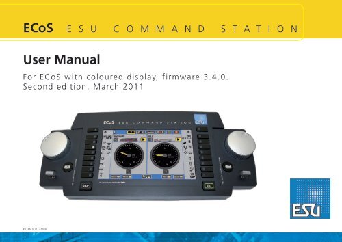
ECoS<br />
E S U C O M M A N D S T A T I O N<br />
<strong>User</strong> <strong>Manual</strong><br />
For ECoS with coloured display, firmware 3.4.0.<br />
Second edition, March 2011<br />
<strong>ESU</strong> P/N 01211-10059<br />
1
Contents<br />
1. Declaration of conformity...........................................3<br />
2. WEEE declaration.......................................................3<br />
3. Important Remarks – Please read this section first......4<br />
3.1. What does M4 mean?................................................. 4<br />
4. Introduction - What can ECoS do?.............................4<br />
5. Unpacking & Set-up...................................................5<br />
5.1. Opening the package.................................................. 5<br />
5.2. Location the device..................................................... 5<br />
5.3. Inserting rechargable batteries..................................... 5<br />
6. Starting up quickly.....................................................6<br />
6.1. Overview of possible connections................................ 6<br />
6.2. Minimal wiring for an initial test.................................. 6<br />
6.3. Overview of control input elements............................. 6<br />
6.3.1. Main menu.............................................................. 7<br />
6.3.2. Touch screen............................................................ 7<br />
6.3.2.1. Calibration............................................................ 7<br />
6.3.2.2. Screen buttons...................................................... 7<br />
6.4. Your first train - call up a locomotive and run it.......... 7<br />
7. Features of the ECoS..................................................8<br />
7.1. Running locomotives................................................... 8<br />
7.1.1. Data formats............................................................ 8<br />
7.1.1.1. Data format Motorola®........................................ 8<br />
7.1.1.2. Range of addresses - Motorola®........................... 8<br />
7.1.1.3. DCC-Format ......................................................... 8<br />
7.1.1.4. RailComPlus.......................................................... 8<br />
7.1.1.5. LGB®-Format extensions....................................... 9<br />
7.1.1.6. Selectrix®.............................................................. 9<br />
7.1.1.7. M4........................................................................ 9<br />
7.1.2. Multi-protocol operation.......................................... 9<br />
7.2. Consisting................................................................... 9<br />
7.3. Running shuttle trains................................................. 9<br />
7.4. Accessories with magnetic drives (solenoids)................ 9<br />
7.5. Routes....................................................................... 10<br />
7.6. Switching panels and track diagrams......................... 10<br />
7.7. Programming decoders............................................. 10<br />
7.7.1. Programming track................................................. 10<br />
7.7.2. Programming On the Main..................................... 10<br />
7.8. Feedback with s88.................................................... 10<br />
7.9. Continue to use your old system with ECoSniffer...... 10<br />
7.10. ECoSlink bus system................................................ 10<br />
7.11. ECoSlot module extension compartment................. 10<br />
8. Wiring details...........................................................11<br />
8.1. Power supply............................................................. 11<br />
8.2. Power supply for powering ECoS............................... 11<br />
8.2.1. Setting the input voltage and output voltage......... 11<br />
8.2.2. Practical voltage settings........................................ 11<br />
8.3. Track connection....................................................... 11<br />
8.3.1. Wiring two-conductor tracks.................................. 12<br />
8.3.2. Wiring three-conductor tracks................................ 12<br />
8.4. Wiring the programming track.................................. 12<br />
8.5. ECoSlink.................................................................... 12<br />
8.6. Computer interface................................................... 12<br />
8.7. Wiring external boosters........................................... 13<br />
8.7.1. Suitable systems..................................................... 13<br />
8.7.2. External booster interface....................................... 13<br />
8.7.2.1. Connecting a DCC-booster................................. 13<br />
8.7.2.2. Connecting a Märklin®-booster.......................... 13<br />
8.7.2.3. Configuring the short circuit switch off................ 14<br />
8.7.3. ECoSBoost wired to ECoSlink bus interface............ 14<br />
8.8. ECoSniffer input (Description 8.8.3)........................... 14<br />
8.8.1. Wiring Märklin® 6021........................................... 14<br />
8.8.2. Wiring a Roco® Locomouse®................................ 14<br />
8.8.3 Description ECoSniffer input.................................... 14<br />
8.9. s88-Input.................................................................. 14<br />
9. Initialisation & Control..............................................15<br />
9.1. Start up..................................................................... 15<br />
9.2. Switching off............................................................. 15<br />
9.2. Stop-button.............................................................. 15<br />
9.3. Go-button................................................................. 15<br />
9.4. Screen saver.............................................................. 15<br />
10. Introduction to operations......................................15<br />
10.1. Joysticks.................................................................. 15<br />
10.2. Keyboad.................................................................. 15<br />
10.3. Main menue - Display mode.................................... 16<br />
10.3.1. Operational mode (running locomotives).............. 16<br />
10.3.2. Turnout control panels.......................................... 16<br />
10.3.3. Turnout control panels and track diagrams........... 16<br />
10.3.4. Set-up.................................................................. 16<br />
10.3.5. Help..................................................................... 16<br />
10.3.6. Status line............................................................ 16<br />
10.4. Switch buttons........................................................ 16<br />
10.5. Data entry fields...................................................... 16<br />
10.6. Choice lists.............................................................. 16<br />
10.7. Slide controller........................................................ 16<br />
10.8. Radio buttons and choice fields............................... 16<br />
11. Run locomotives.....................................................17<br />
11.1. Adding new locomotives......................................... 17<br />
11.1.1. Configure RailComPlus locomotives...................... 17<br />
11.1.1.1. Hints for safe registration of RailComPlus locos......17<br />
11.2.1. Entering M4 locomotives...................................... 17<br />
11.2.1.1. Hints for save registration of mfx®-locos........... 17<br />
11.2.1.2. New registration of M4 locomotives.................. 18<br />
11.2.2. Entering Märklin® locos into the data base.......... 18<br />
11.2.3. <strong>Manual</strong> registration & programming of locos........ 19<br />
11.2.3.1. Data format...................................................... 19<br />
11.2.3.2. Address............................................................. 19<br />
11.2.3.3. Sniffer address................................................... 19<br />
11.2.3.4. Name................................................................ 19<br />
11.2.3.5. Symbol.............................................................. 19<br />
11.2.3.6. Favourite lists.................................................... 19<br />
11.2.3.7. Function mapping............................................. 19<br />
11.2.3.8. Assigning functions with ECoSControl Radio....... 20<br />
11.2.3.9. Speed steps / max speed display........................ 20<br />
11.2.3.10. Direct changing of address and speed steps...... 20<br />
11.2.3.11. Extended decoder settings............................... 20<br />
11.2.4. Indirect entry of a locomotive............................... 20<br />
11.3. Call up a locomotive with the cab........................... 20<br />
11.3.1. Swapping the cabs............................................... 21<br />
11.3.2. Clearing a cab...................................................... 21<br />
11.4. Speedometer display options................................... 21<br />
11.5. Deleting a loco........................................................ 21<br />
11.6. Multi cab display..................................................... 22<br />
11.7. Adjusting locomotive parameters............................ 21<br />
11.8. Interesting information on how to run a loco.......... 22<br />
11.8.1. Conflicts of addresses........................................... 22<br />
11.8.2. „Locking“ - Exclusive access to locomotives.......... 22<br />
11.8.3. Address ranges - recommendations...................... 22<br />
12. Operating consists..................................................22<br />
12.1. Add a new consist................................................... 22<br />
12.2. Assigning a consist to a throttle............................... 23<br />
12.3. Change parameters of consists................................ 23<br />
12.4. Deleting a consist.................................................... 23<br />
12.5. Hints for running consists........................................ 23<br />
13. Switching accessories.............................................23<br />
13.1. Enter new accessories.............................................. 23<br />
13.1.1. Data format......................................................... 23<br />
13.1.2. Name................................................................... 23<br />
13.1.3. Number................................................................ 23<br />
13.1.4. Symbol................................................................. 23<br />
13.1.5. Permanent versus momentary action buttons....... 23<br />
13.1.6. Switching time..................................................... 24<br />
13.2. Setting accessory parameters................................... 24<br />
13.3. Creating a new link for an accessory....................... 24<br />
13.3.1. New link............................................................... 24<br />
13.3.2. Delete a link......................................................... 24<br />
13.3.3. Turn a symbol....................................................... 24<br />
13.4. Switch an accessory................................................. 24<br />
13.5. Delete an accessory................................................. 25<br />
14. Turntable control....................................................25<br />
14.1 Connecting the turntable......................................... 25<br />
14.2. Generating a new turntable.................................... 25<br />
14.2.1. Type of turntable.................................................. 25<br />
14.2.2. Name................................................................... 25<br />
14.2.3. Address................................................................ 25<br />
14.2.4. Configuring tracks running off the turntable........ 26<br />
14.3. Programming the turntable..................................... 26<br />
14.4. Editing the turntable............................................... 26<br />
14.5. Deleting a turntable................................................ 26<br />
14.6. Operating the turntable........................................... 26<br />
14.7. Controlling the turntable with the <strong>ESU</strong> LokPilot......... 26<br />
14.7.1. Configuring the turntable..................................... 27<br />
15. Routes...................................................................27<br />
15.1. Define new route.................................................... 27<br />
15.1.1. Extended settings................................................. 27<br />
15.1.1.1. Name................................................................ 27<br />
15.1.1.2. Tact................................................................... 27<br />
15.1.1.3. Trigger a route with an s88-contact................... 27<br />
15.2. Edit a route............................................................. 27<br />
15.3. Create a link to a route in the turnout control panel...... 28<br />
15.4. Switching a route.................................................... 28<br />
15.5. Deleting a route...................................................... 28<br />
16. Track diagram........................................................28<br />
16.1. Configuring the track diagram................................ 28<br />
16.1.1. Inserting track symbols......................................... 28<br />
16.1.2. Insert an accessory............................................... 28<br />
16.1.3. Insert a route........................................................ 29<br />
16.1.4. References to other panels................................... 29<br />
16.1.5. Turn elements...................................................... 29<br />
16.1.6. Mirroring turnouts................................................ 29<br />
16.1.7. Delete symbols..................................................... 29<br />
16.1.8. Change the name of the page.............................. 29<br />
16.1.9. Highlight a track diagram..................................... 29<br />
16.1.10. Information regarding accessories / routes.......... 29<br />
17. Running trains in „shuttle train” mode...................30<br />
17.1. Configuring a shuttle train line................................ 30<br />
2
17.2. Locos travel „out-and-back”................................... 30<br />
17.3. Cancel shuttle train mode....................................... 31<br />
18. Programming Decoders..........................................31<br />
18.1. DCC-Programming.................................................. 31<br />
18.1.1. Direct Mode (CV-Mode)....................................... 31<br />
18.1.2. Programming on the Main (POM)......................... 31<br />
18.2. Introduction to Motorola®-programming................ 31<br />
18.3. Overview of programming options.......................... 32<br />
18.4. <strong>Manual</strong> programming (DCC)................................... 32<br />
18.4.1. Read CVs............................................................. 32<br />
18.4.2. Write CVs............................................................. 32<br />
18.4.3. Programming on the Main (POM)......................... 32<br />
18.5. <strong>Manual</strong> programming (Motorola®)......................... 32<br />
18.6. Searching the Motorola® address............................ 32<br />
18.7. <strong>Manual</strong> programming (Selectrix®)........................... 33<br />
18.8. Graphic programming............................................. 33<br />
18.8.1. Decoder profile for <strong>ESU</strong> and mfx® decoders......... 33<br />
18.8.2. <strong>Manual</strong> configuration of decoder profiles (DCC)...... 33<br />
18.8.3. Automatic assignment of profiles (DCC)............... 33<br />
18.8.4. Profiles of M4 decoders........................................ 33<br />
18.8.5. Editing decoder settings....................................... 34<br />
18.8.5.1. Download mode............................................... 34<br />
18.8.5.2. Live mode......................................................... 34<br />
18.8.6. More info on profiles............................................ 34<br />
18.9. Programming Märklin® 763xx series signals............ 34<br />
19. ECoSniffer..............................................................35<br />
19.1. Sniffer addresses for locomotives............................. 35<br />
19.2. Hints for using ECoSniffer....................................... 35<br />
19.3. Switching accessories with older digital devices......... 35<br />
20. Devices for the ECoSlink bus..................................35<br />
20.1. Extending ECoSlink................................................. 35<br />
20.1.1. ECoSlink terminal................................................. 35<br />
20.2. Märklin® Mobile Station......................................... 36<br />
20.2.1. Allocating locomotives......................................... 36<br />
20.2.2. Extended settings................................................. 36<br />
21. Configuration menu...............................................36<br />
21.1. General settings...................................................... 36<br />
21.1.1. Setting the language............................................ 36<br />
21.1.2. LCD contrast and brightness................................. 36<br />
21.1.3. Current threshold of the internal booster............. 36<br />
21.1.4. Reset.................................................................... 36<br />
21.1.5. Restarting the ECoS.............................................. 37<br />
21.2. Devices in the system.............................................. 37<br />
21.2.1. 6021® and DCC booster configuration................ 37<br />
21.2.2. ECoSBoost configuration...................................... 37<br />
21.3. Train operations mode............................................. 37<br />
21.3.1. Taking over locomotives....................................... 37<br />
21.3.2. Numbering functions............................................ 37<br />
21.3.3. Starting mode...................................................... 37<br />
21.3.3.1. Starting mode for locomotives........................... 37<br />
21.3.3.2. Turnout control starting mode........................... 37<br />
21.3.4. Change of direction............................................. 38<br />
21.3.4.1. Immediate stop of DCC locomotives................. 38<br />
21.3.4.2. Deactivat. change-of-direction feat. of throttle knob...... 38<br />
21.3.4.3. Delayed change of direction.............................. 38<br />
21.4. Accessories and routes............................................ 38<br />
21.5. Data formats........................................................... 38<br />
21.5.1. Default protocol for new locomotives................... 38<br />
21.5.2. Default protocol for accessories............................ 38<br />
21.5.3. Generated data formats....................................... 38<br />
21.5.3.1. RailCom functions............................................. 38<br />
21.5.3.2. Activating the asymmetric track signal............... 38<br />
21.6. Register new locos.................................................. 38<br />
21.7. Access control......................................................... 38<br />
21.7.1. Lock functions...................................................... 38<br />
21.7.2. Requesting code................................................... 39<br />
21.7.2.1. Changing the code............................................ 39<br />
21.7.2.2. Activating the code........................................... 39<br />
21.8. Deleting objects...................................................... 39<br />
21.8.1. Delete locomotives and consists........................... 39<br />
21.8.2. Deleting M4 locomotives...................................... 39<br />
21.9. General information................................................ 39<br />
21.9.1. Software version.................................................. 39<br />
21.9.2. Serial number....................................................... 39<br />
21.10. Calibrating the touch screen.................................. 39<br />
22. s88-bus-configuration............................................40<br />
22.1. s88 monitor............................................................ 40<br />
23. Operation settings..................................................40<br />
23.1. Current monitor...................................................... 40<br />
23.2. Activating/deactivating modules.............................. 40<br />
24. Computer interface................................................40<br />
24.1. IP Set-up................................................................. 40<br />
24.1.1. <strong>Manual</strong>ly assigning IP-Addresses in Windows....... 41<br />
24.1.2. Assigning an IP-address on ECoS.......................... 41<br />
24.1.3. DHCP-Server in the net......................................... 41<br />
24.2. Web interface......................................................... 41<br />
24.2.1. Firmware update.................................................. 42<br />
24.2.2. Backup configuration........................................... 42<br />
24.2.3. Restore configuration........................................... 42<br />
24.2.4. Reset.................................................................... 42<br />
24.2.5. Resetting the access code..................................... 42<br />
24.2.6. <strong>User</strong>-defined locomotive images........................... 42<br />
24.2.6.1.1. Transmit icons via web interface onto ECoS...... 42<br />
24.2.6.1.2. How to use user-defined loco images............. 43<br />
24.2.6.1.3. How to delete user-defined loco images......... 43<br />
24.2.6.2. Display internal loco images.............................. 43<br />
24.2.6.3. Exchange loco images between devices............. 44<br />
24.2.7. Display touch screen on computer monitor........... 44<br />
24.3. Train control software on your PC............................ 44<br />
25. Fixing bugs.............................................................44<br />
25.1. Rescue mode........................................................... 44<br />
25.1.1. Activating the rescue system................................ 44<br />
25.1.1.1. Rescue system via DHCP.................................... 45<br />
25.1.1.2. Rescue system via Static IP................................. 45<br />
25.2. Execute a factory reset............................................ 45<br />
26. <strong>ESU</strong> Support & Registration...................................45<br />
26.1. Registration............................................................. 45<br />
26.2. Forum..................................................................... 46<br />
26.3. Technical hotline...................................................... 46<br />
27. Service & Repair.....................................................46<br />
27.1. Lump sums for repair & service................................ 46<br />
28. Warranty certificate................................................47<br />
29. Annex....................................................................48<br />
29.1. Technical data......................................................... 48<br />
29.2. Code table for accessory decoders........................... 49<br />
1. Declaration of Conformity<br />
We, <strong>ESU</strong> electronic solutions ulm GmbH & Co KG, Industriestrasse<br />
5, D-89081 Ulm, declare herewith in sole responsibility<br />
compliance of the product<br />
ECoS <strong>ESU</strong> Command Station<br />
to which this declaration is related to , with the following standards:<br />
EN 71 1-3 : 1988 / 6 : 1994 – EN 50088 : 1996 – EN 55014,<br />
part 1 + part 2 : 1993<br />
EN 61000-3-2 : 1995 – EN 60742 : 1995 – EN 61558-2-7 :<br />
1998<br />
ECoS bears the CE-mark according to the guidelines as per<br />
88 / 378 / EWG – 89 / 336 / EWG – 73 / 23 / EWG<br />
The ECoS bears the CE mark.<br />
2. WEEE-Declaration<br />
Disposal of old electrical and electronic devices (applicable in<br />
the European Union and other European countries with separate<br />
collection system).<br />
This mark on the product, the packaging or<br />
the relevant documentation indicates, that<br />
this product may not be treated as ordinary<br />
household garbage. Instead this product has<br />
to be delivered to a suitable disposal point<br />
for recycling of electrical or electronic equipment.<br />
By disposing of this product in the appropriate<br />
manner you help to avoid negative<br />
impact on the environment and health that<br />
could be caused by inappropriate disposal. Recycling of materials<br />
contributes to conserve our natural environment. For more<br />
information on recycling this product please contact your local<br />
administration, the rubbish disposal service or the shop where<br />
you have purchased this product.<br />
Batteries do not belong into household trash!<br />
Please do not dispose of discharged batteries in your household<br />
trash: take them to a collection point at your local town hall<br />
or dealer. Thus you assure an environmentally friendly way of<br />
disposal.<br />
Copyright 1998 - 2011 by <strong>ESU</strong> electronic solutions ulm GmbH & Co KG. Mistakes,<br />
changes resulting in technical advancement, availability and all other rights reserved.<br />
Electrical and mechanical characteristics, dimensions and sketches are subject to<br />
change without prior notice. <strong>ESU</strong> may not be held responsible for any damage or<br />
consequential loss or damage caused by inappropriate use of the product, abnormal<br />
operating conditions, unauthorised modifications to the product, etc. Not suitable<br />
for children under 14 years of age. Inappropriate use may result in injury due to<br />
sharp points and edges.<br />
Märklin® is a registered trademark of Gebr. Märklin® und Cie. GmbH, Göppingen,<br />
Germany. RailCom is a registered trademark of Lenz Elektronik GmbH, Giessen. All<br />
other trademarks are the property of their respective legal owners.<br />
According to its policy <strong>ESU</strong> electronic solutions ulm GmbH & Co KG continues to<br />
develop its products. Therefore <strong>ESU</strong> reserves the right to implement changes and<br />
improvements to any of the products listed in the <strong>ESU</strong> documentation.<br />
Duplication and preproduction of this documentation in any shape or form requires<br />
prior written consent from <strong>ESU</strong>.<br />
3
Introduction - What the ECoS can do<br />
3. Important Remarks-Please read this chapter first<br />
We congratulate you to your purchase of an <strong>ESU</strong> ECoS Digital<br />
Command Station. ECoS is a modern, intelligent model train<br />
control system designed with the future in mind. In a short<br />
time you will experience how easy it is to run trains and other<br />
devices on your layout with ECoS and to discover new undreamt-of<br />
possibilities for your hobby thanks to a unique variety<br />
of functions. Due to new functions you will quickly find out<br />
how easy it is to run your model trains with your ECoS.<br />
This manual will guide you step by step through the multitude<br />
of possibilities of ECoS. However, have one request:<br />
Please read this manual carefully prior to initial operation. Although<br />
ECoS is robustly constructed there is the risk of damage<br />
due to incorrect wiring. If in doubt, avoid any „costly” experiments!<br />
• ECoS is only intended for the use with electrical model train<br />
layouts. Never operate ECoS without paying attention and<br />
never use it for controlling devices designed for transporting<br />
persons.<br />
• ECoS is not a toy. Make sure that children use this device<br />
only when adults are present.<br />
• Only use the power supply provided for ECoS: Other transformers<br />
may lead to reduced output or in extreme cases to<br />
damage of the command station.<br />
• Use the power supply provided with ECoS for the energy<br />
supply for ECoS only and not for any other household appliances.<br />
• Never use Y-adapters in order to provide power to other<br />
devices for your model trains! An unintended connection to<br />
ground could lead to damage or destruction of your ECoS!<br />
• Check the power supply regularly for damage on the<br />
housing or the mains cable. Damaged parts may not be<br />
used under any circumstances! Do not attempt to repair the<br />
power supply! This may be fatal!<br />
• Assure adequate ventilation of the power supply. Do not<br />
install in furniture without sufficient air circulation since this<br />
could lead to overheating or fire!<br />
• ECoS may only be operated with the devices described in<br />
this manual. Any other use as described here is not permitted.<br />
• Only connect devices intended for this purpose to ECoS.<br />
Even if other devices (also from other suppliers) may have<br />
the same plugs and sockets does this not automatically indicate<br />
that such devices may be operated with ECoS.<br />
• Adhere to the wiring diagrams shown in this manual when<br />
connecting your layout. Other circuitry could lead to damage<br />
of ECoS.<br />
• Do not drop your ECoS command station or subject it to<br />
mechanical impact or vibrations. Such rough treatment<br />
could cause breakage of components within the device.<br />
• Never support yourself on the touch screen or sit on your<br />
ECoS.<br />
• The monitor with integral touch screen is a precision part.<br />
Press it only lightly with your finger or the supplied peg (stylus).<br />
Never use hard or pointed objects to avoid un-repairable<br />
damage to the touch screen.<br />
• Never expose your ECoS to rain, humidity or direct sunlight.<br />
In case of high temperature variations (e.g. when you take<br />
your ECoS from the cold car to your comfortably heated<br />
house) please wait for a few hours until the device has adjusted<br />
to the temperature before switching it on.<br />
• When using ECoS outside you must protect it from the elements<br />
under all circumstances! Only keep ECoS outside as<br />
long as you run trains and avoid temperatures below 8°<br />
Celsius or above 30° Celsius.<br />
• Do not use any aggressive chemicals, cleaning solutions or<br />
solvents for cleaning ECoS. Never use liquids or spray for<br />
cleaning the monitor. Instead use a clean slightly (!) moist<br />
cloth and only when ECoS is switched off.<br />
• Do not attempt to open ECoS. Inappropriate handling may<br />
lead to damage of the command station.<br />
3.1. What does M4 mean?<br />
At some points in this catalog you will notice the term „M4“<br />
for the first time rightly wonder what this might mean.<br />
This question can be answered quite simply: from 2009 forward,<br />
M4 is the name data protocol that was chosen by <strong>ESU</strong><br />
to be implemented in their decoders. Decoders with the M4<br />
protocol are one hundred percent compatible with command<br />
using mfx®. At such stations (e.g. Märklin® Central Station®)<br />
they will be recognized automatically<br />
and all playing functions<br />
are available just like when<br />
using mfx® other hand, our<br />
<strong>ESU</strong> command stations using<br />
M4 will recognize all (Märklin®<br />
and mfx® decoders without<br />
any restrictions and will still<br />
work without any problems.<br />
the (mutual) inventor of mfx®<br />
we can assure you of this. In<br />
short: the technique stays the<br />
same, only the name has been<br />
changed.<br />
4. Introduction – What can ECoS do?<br />
ECoS is a state-of-the-art complete digital control system for<br />
model trains of all gauges. ECoS combines several devices in<br />
one unit and a shapely body:<br />
• A multi-protocol digital command station. Suitable for easy<br />
mixed operation of mobile and stationary decoders suitable for<br />
Motorola®, DCC, M4 and Selectrix® protocols.<br />
• Large high-resolution TFT colour display with touch screen. It<br />
serves for displaying information in plain text and very easy<br />
menue-guided operation.<br />
• Two ergonomic cabs with easy to grip throttle knobs, 4-way<br />
joystick and 9 function buttons each.<br />
• An integral booster with up to 4 Ampere output for supplying<br />
„digital power” to your the tracks of your layout. A feedback<br />
decoder as per the latest NMRA DCC standard („Bi-directional<br />
Communication, RailCom®) is supplied as an integral part.<br />
• Sockets for connecting external boosters compatible with DCC<br />
or Märklin® 6017. Simply continue to use your own boosters.<br />
• One socket for wiring the programming track. With this you<br />
can read out and program your mobile decoders independent<br />
from the layout suitable for DCC, Selectrix® and programmable<br />
Motorola®-decoders (e.g. <strong>ESU</strong> LokPilot® mfx®, LokSound®<br />
mfx®).<br />
• A computer interface (10 MBit Ethernet LAN, RJ45) allows you<br />
to download software updates, save and restore your configuration<br />
as well as controlling your layout with a PC (with the aid<br />
of dedicated software by several suppliers).<br />
• ECoSlink high-speed bus. You may connect up to 128 other<br />
devices to ECoSlink. Other handheld (wireless) controllers,<br />
boosters, bus distributors or feedback decoders, they all will<br />
be detected automatically once they are plugged in: this is true<br />
„Plug & Play“.<br />
• s88-feedback bus. This popular feedback system by Märklin®<br />
enables you to control routes or to automate train movements<br />
„shuttle train (shuttle trains).<br />
• ECoSniffer-input. The port for any DCC resp. Motorola®capable,<br />
already available digital command stations: Continue<br />
to use your favourite handheld controllers and accessory keyboards<br />
– not a problem with ECoS.<br />
• The ECoSlot module expansion compartment allows upgrading<br />
of ECoS with new components at a later stage, e.g. a receiver<br />
module for the ECoSControl Radio handheld throttle.<br />
All above mentioned parts and components enable you to run<br />
your trains with never before imagined comfort and ease. You<br />
may fully focus your attention on your trains while ECoS takes<br />
care of the details like a good co-pilot. And here are all the<br />
things you can do with ECoS:<br />
• Run locomotives: ECoS handles up to 16384 locomotives and<br />
stores the name, a symbol, the function buttons and their corresponding<br />
symbols, address and data format. As from now<br />
on you will call up your locomotives by their name and do not<br />
have to remember address numbers any longer!<br />
4
Unpacking & Set-Up<br />
• Controlling accessories. You can assign names and symbols to<br />
up to 2048 turnouts, signals and other accessories with solenoid<br />
drives and comfortably control them with the integral switch<br />
panels.<br />
• Multi-traction (consists) are a basic function for ECoS: Assemble<br />
any locomotives to a consist and control them simultaneously.<br />
• Routes are really no problem for ECoS. Group your accessories<br />
and then switch them together; either manually or triggered by<br />
an s88-feedback contact.<br />
• The integral switch panels (turnout control panels) enable you<br />
to graphically display the topology of your layout and to switch<br />
accessories or routes directly on the panel(s). Several panels<br />
and an extensive choice of symbols allow you to display even<br />
complex layouts.<br />
• The shuttle train mode caters for up to 8 different “out and<br />
back” lines with two each s88 contacts. This enables you to run<br />
shuttle trains between two points in a simple manner.<br />
• The integral turntable control feature displays the Märklin®<br />
turntable on the monitor and enables you to directly select the<br />
desired track position.<br />
• Programming decoders: Due to the monitor programming<br />
becomes as easy as never before: All parameters are shown<br />
in plain text and avoid mistakes. Set your locomotives onto<br />
the programming track or use P.O.M. (Programming On the<br />
Main).<br />
• In most cases you can continue to use your „old” digital system:<br />
Provided it „speaks” DCC or Motorola®, you may connect<br />
it to the ECoSniffer port and thus use all your present<br />
handheld throttles.<br />
5. Unpacking & Set-up<br />
5.1. Opening the package<br />
The ECoS – command station is safely protected in two cartons<br />
when delivered. First open the brown shipping carton at one<br />
end and pull out the printed carton. Now pull out the two-part<br />
blister pack and place it on a table with the monitor of ECoS<br />
facing upwards.<br />
The upper half of the blister is secured to the lower part with<br />
several buttons. No adhesive has been used. Pull both blister<br />
halves apart at each button until you can separate the two<br />
halves.<br />
Please keep the packaging in a safe place for later use. Only<br />
the original packaging guarantees protection from transport<br />
damage. Pack your ECoS into the blister and both cartons prior<br />
to dispatch by mail or parcel service.<br />
5.2. Locating the device<br />
Place ECoS on a flat, clean and dry surface within sight of your<br />
model train layout. Assure a stable position of ECoS and an<br />
optimal distance between yourself and the command station.<br />
The monitor is tilted at 12 degrees against the support surface<br />
and is best suited for a sitting operator (easy reading of text,<br />
etc. on display).<br />
Avoid reflections of bright walls or lighting equipment on the<br />
monitor.<br />
Provide suitable conditions for your ECoS: ideally operate ECoS<br />
at room temperature. Avoid heat sources in the immediate surroundings.<br />
Generally it can be said that any room conditions<br />
that are comfortable for you will be good for ECoS.<br />
Figure 1<br />
5.3. Inserting rechargeable batteries<br />
We recommend always operating your ECoS with batteries in<br />
place. A set of batteries is supplied with your ECoS. The batteries<br />
assure trouble free shutdown by saving all settings in case<br />
of a power cut. This “emergency power supply” is needed in<br />
order to bridge the short time span between power cut and<br />
shutdown of the device.<br />
The batteries may be removed without any problems once the<br />
ECoS has shut down. All settings are safely stored in the flash<br />
memory. The batteries are automatically recharged during operation.<br />
If the ECoS has been turned off for an extended period (summer<br />
break) it should be operated for at least four hours in order<br />
to recharge the batteries sufficiently. Please also take note of<br />
the hints regarding switching off your ECoS in chapter 9.2.<br />
The battery compartment is located at the back of ECoS.<br />
Figure 2<br />
• Remove the cover by pressing the clip in the direction of the<br />
arrow.<br />
• Insert four rechargable batteries in the correct polarity. The poles<br />
(„+“ and „-“) are imprinted in the battery compartment.<br />
• Close the cover of the battery compartment.<br />
• Only use rechargable high-quality batteries or accumulators.<br />
• Remove the rechargable batteries only when ECoS is switched<br />
off (pull mains plug).<br />
• After longer periods without operation (e.g. after the summer<br />
vacation) please remove the rechargable batteries to avoid any<br />
leakage.<br />
• Never attempt to insert ordinary batteries in your ECoS! The<br />
electronics of the charger cannot detect this fact and will try<br />
to recharge such batteries as well.<br />
5
Starting up quickly<br />
6. Starting up quickly<br />
After working through this you will be able to carry out a quick<br />
test of your ECoS command station and to do the „first laps”<br />
with one locomotive.<br />
Please read the entire manual before you wire your ECoS permanently<br />
to your layout.<br />
6.1. Overview of possible connections<br />
All sockets are located at the back of your ECoS command<br />
station:<br />
Prog-Track<br />
Power<br />
Main-Track<br />
AUX<br />
ECoSLink Connect<br />
ECoSLink Connect<br />
ECoSLink Connect<br />
Figure 3<br />
ECoSLink Extend<br />
Network<br />
Booster<br />
ECoSniffer<br />
s88<br />
Power: Socket for power supply of ECoS and your layout.<br />
Connect this socket only with the power<br />
supply delivered with ECoS.<br />
Prog-Track: Two-way socket (5.08mm contact spacing) for<br />
programming track (optional)<br />
Main-Track: Two-way socket (5.08mm contact spacing) for<br />
mainline<br />
AUX: Socket for future extensions. Currently not in<br />
use.<br />
ECoSlink: Three seven-way Mini-DIN sockets for direct<br />
connection of external ECoSlink devices<br />
(handheld controllers, boosters, feedback decoders,<br />
etc.)<br />
ECoSlink Extend: Nine-way mini-sockets (DIN) for wiring busextension<br />
modules to ECoSlink (up to 100m<br />
total length)<br />
Network: 10MBit Ethernet RJ45 socket for connecting<br />
ECoS to a computer network<br />
s88: Six-way pin-connector for wiring Märklin®<br />
s88-compatible feedback decoders (up to 32<br />
modules)<br />
ECoSniffer: Two-way socket (3.5mm contact spacing) for<br />
connecting existing digital systems. Wire the<br />
track terminals of your „old” command station<br />
to this socket.<br />
Booster: Five-way socket (3.5mm contact spacing)<br />
for wiring external boosters compatible with<br />
DCC-standards or Märklin® 6017.<br />
6.2. Minimal wiring for an initial test<br />
• Connect the power supply to the appropriate socket of ECoS.<br />
• Wire the two terminals „Main” to your test track.<br />
To the<br />
power<br />
supply<br />
B 0<br />
B 0<br />
Figure 4<br />
With DCC-systems polarity is not an issue.<br />
2-digit<br />
track<br />
3-digit<br />
track<br />
If you use three-rail-tracks you must observe the correct polarity<br />
(“B”, “0”); otherwise many older locomotives and accessories<br />
(e.g.: k83, k84) may not function properly.<br />
b)<br />
k)<br />
c)<br />
a)<br />
i)<br />
Figure 5<br />
6.3. Overview of control input elements<br />
All control input elements of ECoS are located on the top of<br />
the housing as per Figure 5 below.<br />
a) Function buttons on the left. The headlight function as well<br />
as F1 to F8 of each locomotive may be activated directly<br />
by pressing these buttons. An integral LED in the buttons<br />
displays their status.<br />
b) Left throttle knob with definitive end position and changeof-direction<br />
function. Turning the knob clockwise increases<br />
the speed while turning anti-clockwise reduces the speed..<br />
The position of the knob corresponds with the speed. Turning<br />
the throttle knob to the left beyond the „Zero”-position<br />
to a clearly audible and mechanical „click” changes the<br />
direction of travel.<br />
c) Four-way joystick with centre-click-function serves for navigating<br />
in the menues, selecting locomotives and to trigger<br />
the whistle („Playable Whistle“) of locomotives equipped<br />
with suitable decoders.<br />
d) “Stop” button: immediately turns off the track power. Also<br />
serves for turning off the ECoS at the end of operations<br />
(more on this in chapter 9.2).<br />
e) “Go” button: turns on the track power of the command<br />
station: power is available at the track terminals.<br />
f) Function buttons. The first 8 functions of each locomotive<br />
can be directly activated by pushing one of these buttons.<br />
g) Throttle (right hand side) with limit stop and change-ofdirection<br />
function.<br />
h) Storage space for stylus.<br />
i) Touch-sensitive touch screen with LCD display.<br />
j) Stylus<br />
k) Locomotive selection button. Calls up the locomotive menu<br />
for the respective cab.<br />
d) e)<br />
h)<br />
g)<br />
j)<br />
f)<br />
6
Your first train<br />
6.3.1. Main menu<br />
Besides the operating controls the touch screen provides more<br />
important information for each displayed locomotive.<br />
a) Name of locomotive: displays the name of the locomotive<br />
(can be made up of letters and numbers).<br />
b) Locomotive symbol: displays the symbol of your choice (can<br />
be freely selected).<br />
c) Speedometer display: shows the current speed.<br />
d) Speed indicator: displays the current speed step. The range<br />
of values depends on the data format of the locomotive decoder.<br />
Subject to the locomotive settings the speed in km/h<br />
may displayed instead of the speed steps.<br />
e) Direction of travel „Forward“: is highlighted, if the locomotive<br />
travels forward.<br />
f) Direction of travel „Reverse“: is highlighted, if the locomotive<br />
travels backwards.<br />
g) Locomotive selection button: Pressing this screen button<br />
on the touch screen opens the locomotive selection menu.<br />
Press this screen button every time you wish to run another<br />
locomotive with this cab. Alternatively you may press the<br />
locomotive selection button.<br />
h) Locomotive menue: after pressing this screen button you<br />
can enter, edit or delete new locomotives or consists or assign<br />
shuttle trains.<br />
i) Function button symbols. Depending on the data format<br />
and setting you may switch on and off up to 20 functions in<br />
each locomotive by touching the appropriate symbol.<br />
f)<br />
a)<br />
Figure 6<br />
c) b)<br />
i) g)<br />
h)<br />
e)<br />
d)<br />
6.3.2. Touch screen<br />
As the name says the touch screen responds to contact with<br />
your finger or with the stylus. Please do not use any hard or<br />
pointed objects; this could lead to permanent scratches on the<br />
surface.<br />
6.3.2.1. Calibration<br />
The touch screen is normally calibrated ex works. Calibration<br />
allows equalising any manufacturing tolerances. After a software<br />
update the device may not be calibrated any more. In that<br />
case the calibration window opens immediately after starting<br />
the ECoS.<br />
Push the small cross on the screen with the “stylus” provided.<br />
The cross will jump to another position immediately. Try to<br />
press this symbol as close to it’s centre as possible. After you<br />
have repeated this process three times calibration is completed.<br />
For further information see page 37, chapter 21.9.<br />
Confirm the calibration by pressing the screen button on the<br />
left of “Save calibration and exit this menu”.<br />
6.3.2.2. Screen buttons<br />
At all times certain information as well as screen buttons are<br />
displayed on the screen. Whenever you press one of these<br />
screen buttons an action will be triggered.<br />
Examples for screen buttons:<br />
Touching this screen button confirms an action.<br />
Touching this screen button cancels an action; any data entered<br />
during this particular process will not be saved.<br />
In some menues you can select or cancel certain options by<br />
touching the screen button („ticking them off electronically”).<br />
Choice lists are opened by touching the right arrow on the heading<br />
of the list. Then a list of available elements appears.<br />
Slider: Slide controllers enable you to comfortably set values.<br />
Input fields are for entering text or numbers with the aid of the<br />
display keyboard.<br />
6.4. Your first train – call up a locomotive and run it<br />
We want to show you how easy it is to enter, call up and run a<br />
locomotive. First make sure that ECoS is connected as per the<br />
instructions and turn on the power supply.<br />
ECoS needs one to two minutes for initialisation („start-up“).<br />
A small square at the bottom of the monitor runs from left<br />
to right to indicate this process. As soon as ECoS is ready the<br />
„Go”-button lights up (green). During the booting it could<br />
happen that the screen switches off from time to time. This is<br />
a normal occurance.<br />
Any audible chirping from the command station is quite normal<br />
and no reason for concern.<br />
Before we can run a locomotive we must enter this locomotive<br />
in the internal locomotive list of the ECoS. In our example we<br />
assume that you have a locomotive operating with the Motorola®<br />
data format that does not report automatically to the<br />
command station.<br />
Press the screen button “Locomotive menu” on the display and<br />
select ”New locomotive” and then “<strong>Manual</strong> entry”.<br />
Figure 7<br />
In our example we would like to run a locomotive with the<br />
address “44”. Therefore we have to replace the number in this<br />
field (currently: 3) by the desired number.<br />
Press the screen button “Display keyboard” in order to open<br />
the data entry window.<br />
Press the “Delete” screen button in order to cancel the number<br />
“3”. Then type “44” and confirm by pressing “Ok”.<br />
Figure 8<br />
In our example we assume<br />
that this locomotive operates<br />
in the Motorola® format.<br />
This is the default setting. If<br />
you wish to run this loco in<br />
the DCC format, press the<br />
arrow behind “Data format”<br />
and select “DCC 28”.<br />
Confirm your entry by pressing<br />
“Ok”. Then you will<br />
arrive at the train control<br />
screen (cab) automatically;<br />
the newly entered locomotive<br />
is called up and ready to<br />
Figure 9<br />
run.<br />
• Turn the throttle to the right and the locomotive will start moving.<br />
The speedometer will display the correct speed right away<br />
while the speed steps for precise control are displayed as well<br />
(refer to Fig. 6d).<br />
7
Features of the ECoS<br />
• Turn the throttle to the left beyond<br />
the Zero position until you hear the<br />
click and the direction of travel will<br />
be changed. The throttles are also<br />
motor driven. Whenever you turn<br />
the throttle to the left and thus<br />
change the direction you may simply<br />
release the throttle and it will<br />
automatically return to the Zero Figure 10<br />
position.<br />
• You can turn on or off the locomotive functions by pressing the<br />
appropriate buttons or by touching the screen buttons.<br />
How to continue from here? Please take the time to work<br />
through the following chapters. Please take into account that<br />
it will take some time to get to know the manifold new functions.<br />
Be patient and take your time to try out some of the<br />
features. We wish you lots of fun in discovering your “new”<br />
ECoS.<br />
7. Features of the ECoS<br />
ECoS is a state-of-the-art digital command control system and<br />
offers many features. We want to explain the possibilities and<br />
some technical background in greater detail. The detailed operating<br />
instructions are given in chapter 10. If you wish you may<br />
turn to these pages right now if you do not want to know the<br />
technical background at this stage.<br />
7.1. Running locomotives<br />
ECoS can control up to 16,384 locomotives simultaneously.<br />
Of course, this is only a theoretical number that will hardly be<br />
reached in practice. The electrical power required for so many<br />
locomotives would far exceed the maximum number of 128<br />
boosters. The response times for each locomotive would also<br />
be unacceptably long. As a multi-protocol-system ECoS supports<br />
several data formats for running your locomotives.<br />
7.1.1. Data formats<br />
7.1.1.1. Data format Motorola®<br />
Motorola® I („Old“ Motorola®-format)<br />
First generation Märklin® locomotives support this format in<br />
which the status of the lighting function is transmitted besides<br />
14 speed steps. Only when changing direction a special signal<br />
will be sent to the locomotive. However, it is possible that the<br />
direction status of the locomotive and the command station<br />
status for this loco do not correspond initially. In this case you<br />
would have to change direction once more to assure a corresponding<br />
status.<br />
Motorola® II (so-called new data format)<br />
Besides the 14 speed steps a signal indicating direction of travel<br />
is transmitted continuously. The info regarding direction always<br />
corresponds between command station and locomotive.<br />
The status of F1 to F4 is transmitted in a separate packet. This<br />
is only generated if the status of at least one function has changed.<br />
Advanced decoders store this information locally to assure<br />
that it corresponds with the command station even in case of<br />
a power interruption.<br />
ECoS does not differentiate between Motorola® old and new<br />
but transmits (by using a special method.) data packets in both<br />
formats.<br />
In ECoS we call this mode „Motorola14“.<br />
Märklin® built an extension into their decoder series 6090x to<br />
provide 27 speed steps: the so-called „half speed step“ between<br />
the actual speed steps increases the resolution. The command<br />
station must transmit specific command sequences in order<br />
to achieve this. ECoS knows this mode as „Motorola27”.<br />
If you run a locomotive in „Motorola27” mode and you notice<br />
that functions are only activated at every second speed step,<br />
then your decoder does not support the 27 speed steps. Please<br />
switch to „Motorola14”.<br />
<strong>ESU</strong> extended all decoders to suit the Motorola®-format by an<br />
additional mode, namely „Motorola28”. This operates with 28<br />
real speed steps.<br />
If you want to run a loco in “Motorola 28“ format and you notice<br />
that the functions are only working at every second speed<br />
step then your decoder does not support the 28-speed step format.<br />
Run these locomotives with the “Motorola 14” format.<br />
Märklin® released some function models to the market (e.g.<br />
4998, 4999 or 49960, turning crane 7651 or Gauge 1 cars<br />
58115) that have to be controlled with a data package different<br />
to the one for the locomotives. In terms of its design<br />
this data package is similar to the ones for turnouts. We call it<br />
“Motorola Fx 14”.<br />
7.1.1.2. Range of addresses - Motorola®<br />
Märklin® defined 80 addresses for its original digital system.<br />
Since this number is far too small for many applications several<br />
decoder suppliers extended the range. <strong>ESU</strong> LokSound V3.4<br />
M4, LokPilot V3.0 M4 and LokPilot V3.0 support 255 addresses<br />
in the Motorola-format.<br />
7.1.1.3. DCC-Format<br />
The DCC standards published by the North American NMRA<br />
(National Model Railroad Association) is based on a development<br />
by the German company Lenz Elektronik.<br />
In DCC-format up to 10.239 addresses, up to 21 functions and<br />
up to 128 speed steps are encoded. In practice only 126 speed<br />
steps can be used, the others are reserved for the emergency<br />
stop function. The absolute direction of travel is also encoded.<br />
How many of these addresses, functions and speed steps are<br />
actually available depends on the type of decoder and the<br />
command station. ECoS supports currently all known DCC formats.<br />
We differentiate between 14, 28 and 128 speed steps. In the<br />
latter case 126 speed steps can actually be utilised.<br />
Subject to the mode in which you want to run your DCC locomotive<br />
please select „DCC14”, „DCC28” or „DCC128” as<br />
data format.<br />
Please bear in mind, that the information regarding the speed<br />
steps transmitted by ECoS has to correspond with the speed<br />
step setting of the decoder. A data packet for „DCC14” is for<br />
instance identical to one for „DCC128”, but will be „understood”<br />
differently by the decoder. If the settings do not correspond<br />
then the headlights of the locomotive will blink slowly<br />
while the locomotive is accelerating.<br />
If you are not sure which DCC modes are supported by your<br />
decoder try DCC 28 first. This is the compulsory mode as stated<br />
by the NMRA. All <strong>ESU</strong> DCC decoders detect the number<br />
of speed step automatically. You may just as well start with<br />
DCC 128.<br />
7.1.1.4. RailComPlus<br />
RailComPlus® is the logical further development of DCC and<br />
RailCom® and supplements their basic technology with a packet<br />
of new functions such as simplyfing the control of locomotives,<br />
turnouts and signals.<br />
The automatic registration procedure RailComPlus® has been<br />
developed by <strong>ESU</strong> and is based on RailCom® which was invented<br />
by Lenz®. It is another milestone in the history of bidirectional<br />
communication. New RailComPlus® packets make<br />
a faster transmission of instructions to the decoders possible.<br />
This also improves the bandwith of DCC.<br />
A loco which is equipped with a RailComPlus® decoder will automatically<br />
register itself to the command station and imform<br />
8
Features of the ECoS<br />
the station about its name and address. Via RailComPlus® the<br />
decoder is able to communicate the loco´s range of functions.<br />
You will recognise which functions are involved and if it is a<br />
moment function (e.g. for a whistle) or a permanent function<br />
(e.g. engine noise).<br />
If the locomotive is operated with a different command station,<br />
e.g. your club station, it will register itself automatically to the<br />
club command station (which is compatible with RailComPlus)<br />
or it can be operated with every DCC command station via its<br />
DCC address.<br />
7.1.1.5. LGB®-Format extensions<br />
LGB® uses the DCC protocol for operating garden railways.<br />
The old Lokmaus® had only one function button „F1” besides<br />
the lighting button. But how could you switch so many functions<br />
with just one button?<br />
The „solution” was what became know as the „sequential<br />
function status mode”. The user knew if he for instance wanted<br />
to switch function F3, he had to press F1 three times in a<br />
row. The decoder counts the number of status changes and<br />
then switches the desired function. The disadvantage of this<br />
method is that functions with higher numbers (e.g. F8) take<br />
longer to respond, since several „on-off” commands have to<br />
be transmitted.<br />
Should you have any LGB® locos with such decoders and you<br />
want to run them with ECoS select the „LGB” format. It corresponds<br />
to the „DCC14” format, but the functions are activated<br />
sequentially in the background.<br />
Modern LGB® locos or such locos with <strong>ESU</strong> LokSoundXL decoders<br />
understand alternatively „DCC28” resp. „DCC128”. If in<br />
doubt, simply try it.<br />
7.1.1.6. Selectrix®<br />
ECoS can control all locos with Selectrix® decoders. In this<br />
mode 112 addresses, 31 speed steps and two function buttons<br />
(Light and F1) are available. ECoS calls this mode „Selectrix“.<br />
7.1.1.7. M4<br />
Of course the ECoS also supports the M4 protocol. When using<br />
the appropriate decoders such as Märklin® mfx® decoders or<br />
<strong>ESU</strong> LokSound M4 resp. <strong>ESU</strong> LokPilot M4 the command station<br />
automatically detects and recognises such decoders and<br />
incorporates them into the operations. Simply assign names to<br />
these locomotives! In an M4 system there are no addresses; all<br />
locomotives with M4 or mfx® decoders report automatically to<br />
the command station. You will immediately see the locomotive<br />
name on the display. This is true “Plug & Play”. Of course you<br />
may change the name at any time should you wish to do so.<br />
For instance you could convert a “class 232” to “Ludmilla“.<br />
In M4 mode there are up to 16 functions per locomotive. The<br />
appropriate symbol is displayed on the screen of the command<br />
station next to the function button. The decoder also informs<br />
the command station if a function is set to momentary action<br />
(e.g.: for the whistle or horn) or a continuous function (e.g.:<br />
for the pantograph).<br />
Every M4 decoder supports 124 speed steps for smooth acceleration.<br />
With the software 3.0.0. it is now also possible to run locomotives<br />
in M4 mode with 28 speed steps. This helps to reduce<br />
the number of turns of the throttle considerably until the maximum<br />
speed is reached.<br />
7.1.2. Multi-protocol operation<br />
ECoS can transmit all above formats in sequence. Thus each<br />
loco can be controlled with its own data format. Mixed operation<br />
of different decoders on the same track is generally possible<br />
without any problems.<br />
Some very old decoders may not be able to function properly if<br />
another format is transmitted to the track besides „their own”.<br />
This may result in uncontrolled acceleration, blinking headlights<br />
or other abnormal behaviour.<br />
The very first series of Märklin® signals 763xx may get confused<br />
if you run other data formats besides Motorola®.<br />
If there is no colour mark at the underside of your Märklin® signals<br />
we recommend to get them updated. A software update<br />
makes them suitable for multi-protocol operation.<br />
7.2. Consisting<br />
ECoS enables you to set up and control consists of two or more<br />
locos comfortably. All locos are listed in the memory of ECoS.<br />
ECoS transmits separate signals (in the required data format)<br />
to each loco of the consist. This happens at high speed so the<br />
locos work like one. Therefore it is possible to operate and display<br />
consists with locomotives whose decoders cannot support<br />
consist addresses. Furthermore it is also possible to form consists<br />
consisting of locomotives with different decoder types and<br />
protocols.<br />
Locomotives running in a consist should have uniform characteristics.<br />
If necessary adapt the locomotives by reprogramming<br />
the acceleration rates and maximum speeds prior to forming<br />
to a consist.<br />
You may assign a name and symbol to a consist in ECoS in<br />
the same way as for a loco. A consist is always run with 128<br />
speed steps.<br />
The available functions in a consist are determined by the leading<br />
loco who’s functions will be displayed on the monitor. The<br />
activated functions will be signalled to all locos in the consist.<br />
Locos of a consist can be called up on another throttle, but<br />
they cannot actually be run with that throttle.<br />
7.3. Running shuttle trains<br />
Many model train enthusiasts do not want to run their trains<br />
simply „in circles“ but want to have real point-to-point operation.<br />
Branch lines onto mountains with terminal stations at<br />
either end, small branch lines with a connection to a main line,<br />
but also modular layouts are typical examples for such pointto-point<br />
scenarios.<br />
In ECoS we differentiate between shuttle tracks and shuttle<br />
trains (locos) that run on these tracks (out and back). While the<br />
tracks have to be set up only once it is quite possible to have<br />
different locos on such a track. You may change the locos and<br />
easily determine which trains should serve a particular branch<br />
line.<br />
ECoS can handle up to 8 shuttle lines and run one loco each on<br />
each of these 8 lines. ECoS slows down the trains automatically<br />
when they reach the end of the line, changes the direction and<br />
lets the loco depart after a pre-determined layover time.<br />
To detect the stopping point we use contact inputs of the s88<br />
bus. One s88-input is needed for each stopping point.<br />
Such trains are stored in the virtual memory of ECoS. Thus this<br />
feature is available regardless of the decoder type.<br />
7.4. Accessories with magnetic drives (solenoids)<br />
One of the main features of ECoS is controlling accessories /<br />
turnouts. By magnetic accessories we mean any device that is<br />
operated by one or more solenoid drive. Amongst others these<br />
are turnouts, signals, un-couplers or relays to switch lights or<br />
motors.<br />
ECoS can switch such devices via an accessory decoder.<br />
Such stationary decoders are available from many manufacturers.<br />
The most popular is probably the Märklin® K83 ands compatible<br />
models. All such decoders can be used provided they<br />
• are compatible to Märklin® K83 resp. to Märklin® K84 and<br />
understand the Motorola protocol or<br />
• can process the appropriate DCC-format. DCC-accessory decoders<br />
must comply with the „DCC accessory decoder“ standards.<br />
Some accessory decoders by Roco® behave like loco decoders<br />
to enable them to work with the Lokmaus®2. Such decoders<br />
can only be operated with ECoS provided they can be set to a<br />
DCC-compatible mode.<br />
With the SwitchPilot and the SwitchPilot Servo <strong>ESU</strong> offers two<br />
versatile, affordable decoders that work perfectly with the<br />
ECoS.<br />
Wire accessory decoders as described in the manual. Some accessory<br />
decoders are suitable for an external power supply for<br />
the solenoids. We recommend a separate power supply for all<br />
larger layouts: definitely use a separate transformer. Do not<br />
use the <strong>ESU</strong> power supply for t his purpose.<br />
Please observe the correct polarity of the track power when<br />
using k83 / k84 or compatible decoders.<br />
Besides the classic accessory applications (turnouts, signals) the<br />
ECoS can also control Märklin® turntables. The turntable will<br />
be displayed on the screen.<br />
Similar to the locomotives, accessories are stored in lists of the<br />
ECoS. Each accessory may be given a name and a pictogram.<br />
This pictogram represents the type of function. The ECoS differentiates<br />
between two-, three- and four-aspect accessories. For<br />
the three- and four-aspect accessories it is assumed that the<br />
second drive will be wired to the address following the one of<br />
first drive of the same accessory.<br />
9
Features of the ECoS<br />
Example:<br />
For a three-way turnout with the first address of 51 the second<br />
address is automatically 52. The red output of the following<br />
address (in this case: 52) cannot be used for other devices.<br />
ECoS offers an integral control panel for turnouts with 74 levels<br />
(sub panels) with 16 each accessories. Thus you can arrange<br />
your turnouts in groups and manually call them up when<br />
necessary.<br />
7.5. Routes<br />
In practice it is often useful to switch groups of turnouts and signals<br />
and bring them into a pre-defined status instead of switching<br />
them individually. ECoS allows you to combine them to<br />
a so-called route. Switching a route is done in the same way as<br />
switching an individual turnout except that all devices that are<br />
part of this particular route are quickly switched in sequence on<br />
after another to reach the required status.<br />
Routes are also stored internally and can be displayed with a<br />
specific symbol on the turnout control panel. ECoS can handle<br />
up to 1024 routes with 256 individual devices each.<br />
Each accessory can be part of as many routes as desired and, of<br />
course, with different status or aspect.<br />
ECoS transmits the appropriate signals in sequence – with an<br />
adjustable gap between the individual signals. The duration of<br />
the pulse depends on the type of accessory.<br />
Routes can also be switched with s88 contacts: you can link<br />
any s88 contact with any route. Thus it is possible to arrange<br />
sequential processes and block protection.<br />
7.6. Switching panel and track diagrams<br />
The ECoS offers an integral track diagram feature. This enables<br />
you to display the topology of your layout on the screen and<br />
to switch accessories and routes directly on the track diagram.<br />
Each panel has 23 x 11 fields for the entry of symbols. With the<br />
available symbols you can draw just about any track configuration.<br />
Larger layouts can easily be divided over several panels.<br />
Direct references to other panels assure quick and easy access<br />
without the need of time consuming searching.<br />
7.7. Programming decoders<br />
In principle the command station “supports” three types of<br />
programming and two types of protocols: The ECoS supports<br />
both DCC programming as well as Motorola® and M4 programming.<br />
7.7.1. Programming track<br />
The programming track must be completely (!) isolated from<br />
the rest of the layout and must be wired directly to the programming<br />
track output of ECoS.<br />
There should always be only one loco on the programming<br />
track at any point in time. You may read out and write new<br />
values. All DCC decoders are suitable for programming on the<br />
programming track as well as programmable Motorola® decoders<br />
(e.g. LokSound M4, LokPilot M4). DCC decoders cannot<br />
only be completely re-programmed on the programming track;<br />
it is also possible to read the values.<br />
7.7.2. Programming On the Main<br />
DCC decoders can be re-programmed directly on the main<br />
(also known as „Programming On Main“ or „POM“). Thus the<br />
protocols DCC, M4, Selectrix® and Motorola® are supported.<br />
7.8. Feedback with s88<br />
ECoS offers a factory built-in galvanically isolated (!) input for<br />
the very popular s88-modules. They serve as track occupancy<br />
detectors and may be used for controlling routes and shuttle<br />
train operations.<br />
The s88-bus consists of up to 32 s88-modules that can process<br />
either 8 or 16 feedback signals each. These modules are wired<br />
in a „chain” (bus). s88-modules are available from various manufacturers.<br />
The number of existing s88-modules is configured in ECoS in<br />
such a way that response times are as short as possible: since<br />
the modules are checked continuously in sequence, only really<br />
existing modules should be monitored.<br />
7.9. Continue to use your old system with ECoSniffer<br />
ECoSniffer represents a very special feature of ECoS. It allows<br />
you to use your existing digital system even when upgrading to<br />
ECoS. Simply wire the track output of your old system to the<br />
ECoSniffer sockets. ECoSniffer then monitors the signals transmitted<br />
by your old system and „translates” them into ECoS<br />
commands.<br />
Therefore it is possible to use any existing command station as<br />
long as it is suitable for either Motorola® or DCC since ECoSniffer<br />
is multi-protocol-capable (since the update V3.0.0).<br />
It „understands” commands for locos in DCC (14, 28 or 128<br />
speed steps, auto-detection, up to 12 function buttons), Motorola®<br />
(14 speed steps, 80 addresses, Motorola® old and new,<br />
up to 4 function buttons) as well as commands for accessories<br />
in DCC and Motorola®. All other commands from the old system<br />
(perhaps programming commands) will be ignored.<br />
One can connect only one digital command station to the<br />
ECoSniffer. The number of cabs that can be connected to your<br />
old system is subject to the limitations of your old command<br />
station. Thus you may for instance hook up your “Lokmaus”<br />
system with up to 32 “Lokmaus” cabs or your Loconet® command<br />
station with all its connected cabs and continue to use<br />
them as before.<br />
If you wish to control accessories with your old system you<br />
must first enter them locally in your ECoS. Otherwise the<br />
commands will be disregarded. Chapter 13 explains how to<br />
enter accessories. In the same manner locomotives that you<br />
want to control via your old system must be entered in the<br />
memory of your ECoS. Chapter 11 provides details.<br />
7.10. ECoSlink bus system<br />
Our bus system ECoSlink allows for the extension of your ECoS<br />
command station. You may connect external handheld throttles,<br />
feedback modules, boosters and other extensions. ECoSlink<br />
is based on the CAN industrial standard, is suitable for a<br />
maximum cable length of 100 metres and provides excellent<br />
data transmission. ECoSlink operates with 250 kBit / second<br />
and is ”hot-plug” and „plug&play” capable. All devices report<br />
automatically to the system and can be removed or re-connected<br />
during operation. The ECoSlink system can comprise of up<br />
to 128 devices. You will find more details in chapter 20.<br />
7.11. ECoSlot module extension compartment<br />
On the underside of the ECoS housing is a compartment suitable<br />
for extension modules. Thus ECoS can be extended.<br />
<strong>ESU</strong>, for instance, offers a suitable receiver module for the radio<br />
control cab “ECoSControl Radio”. This receiver expands your<br />
ECoS with a wireless cab. A real advantage of your ECoS!<br />
10
Wiring details<br />
8. Wiring details<br />
8.1. Power supply<br />
ECoS gets its power via a 2.1mm DC-socket. The secondary<br />
voltage corresponds with the track voltage; voltage stabilising<br />
or adjustments take place within the power supply, not within<br />
the command station. ECoS has its own internal protective circuitry<br />
for under-voltage and overload (-current).<br />
<br />
Outside: „-“<br />
Supply voltage:<br />
Supply current:<br />
14V to 22V AC or DC<br />
max. 5A<br />
• The peak voltage of the transformer may not exceed 22V in<br />
open circuit operation.<br />
• The use of other power packs may lead to the destruction<br />
of the ECoS.<br />
8.2. Power supply for powering ECoS<br />
A power supply with the following characteristics is delivered<br />
with ECoS:<br />
VIn:<br />
100V – 240 V AC, 50 / 60 Hz<br />
Input current: 1.8A max.<br />
VOut: adjustable from 15V - 21V DC, stabilised<br />
Output current: 5A max.<br />
Plug: DC plug, 2.1mm, 1.8m flying lead<br />
c)<br />
a) Power-LED (red)<br />
b) Output socket (low voltage)<br />
c) Main socket<br />
Inside: „+“<br />
Figure 11<br />
Figure 12<br />
a)<br />
b)<br />
• Please use the power supply provided with ECoS solely for<br />
powering ECoS. Do not use it for other household appliances.<br />
• Check the power supply regularly for any visible damage of<br />
the housing or the mains cable. Damaged parts may never<br />
be used! Do not attempt to repair the power supply! Extreme<br />
danger – risk of fatal injury!<br />
• Make sure there is sufficient ventilation around the power<br />
supply. Mounting in furniture without air circulation may<br />
lead to overheating of even fire!<br />
• First connect the mains cable with the appropriate socket<br />
of the power pack and then plug it into a suitable power<br />
outlet.<br />
• Never use V adapters for connecting the power pack to<br />
other devices besides the command station! This could<br />
cause an inadmissible contact to ground that could lead to<br />
the destruction of your command station!<br />
8.2.1. Setting the input voltage and output voltage<br />
The power pack generates a stabilised voltage that serves to<br />
power your model train layout. The output voltage must be<br />
adjusted to the appropriate value subject to the scale of your<br />
trains.<br />
For this purpose there is a small, round opening at the front of<br />
the power pack that allows you to set the voltage with the aid<br />
of a screw driver:<br />
Left hand limit: ca. 14.5V<br />
Right hand limit: ca. 21.5V<br />
8.2.2. Practical voltage settings<br />
14V<br />
Figure 13<br />
21V<br />
We recommend the following settings for the different scales:<br />
• N gauge:<br />
15V - 16V<br />
• H0 DC (DCC): 16V - 18V<br />
• H0 three-rail-system: 18V - 20V<br />
• 1 gauge:<br />
18V - 21V<br />
• G gauge:<br />
20V - 21V<br />
The integral current monitor shows you the corresponding output<br />
voltage. With the aid of this monitor you can determine<br />
the desired voltage precisely. It is explained in greater detail in<br />
chapter 23.<br />
We recommend proceeding as follows:<br />
• Start your command station<br />
• Open the current monitor<br />
• Turn the adjustment wheel slowly until the desired voltage is<br />
displayed.<br />
8.3. Track connection<br />
The tracks are connected via a two-way socket with a removable<br />
plug. Please make sure you us cables of adequate size<br />
for your track power. We recommend wires of at least 1.5mm²<br />
(better: 2.5mm²) cross section. In larger layouts connect track<br />
power every two meters to the tracks.<br />
<br />
Figure 14<br />
ECoS uses an H4-bridge (full bridge) for the track power. Therefore<br />
with ECoS – contrary to older Märklin® systems - there is<br />
no „Common” (Ground).<br />
Nevertheless it is advisable to use a common ground (normally<br />
the rails) in existing three-rail-systems with several power districts<br />
(boosters).<br />
• Never connect another digital system or analogue transformer<br />
to the same circuit as ECoS. Your ECoS may be damaged<br />
or destroyed!<br />
• Please observe the need for the correct separation of all<br />
power districts should your layout be divided in several such<br />
districts. As normal practice the centre-rail will be isolated.<br />
The outer rails may form the common ground provided<br />
each booster has its own power supply (transformer).<br />
• ECoS supplies up to 4A track current. Always consider if you<br />
actually need such a high output current. In case of a short<br />
circuit your locos may be damaged and there may be risk of<br />
fire! Reduce the maximum current to a sensible level. Also<br />
refer to chapter 21.1.3.<br />
Remove all capacitors that may possibly haven been wired to<br />
the track power supply cable in your layout. They would cause<br />
a strong heat build-up of ECoS and impair the power output.<br />
Almost in every connecting track in an analogue starter kit<br />
(Roco®, Märklin®) are resp. were capacitors installed.<br />
11
Wiring details<br />
8.3.1. Wiring two-conductor tracks<br />
Wiring takes place as shown. Polarity is not an issue (for DCC<br />
or Selectrix®).<br />
<br />
B 0<br />
2-conductor<br />
track<br />
8.4. Wiring the programming track<br />
ECoS has a separate low power output for the programming<br />
track (max current 1A). The same type of socket is used as for<br />
the mainline connection. Wire a section of track to this output<br />
that is completely isolated from the rest of the layout, ideally<br />
some short stub track.<br />
<br />
Should you wish to connect more than three devices you have<br />
to extend the bus with a bus-distribution-module. Either the<br />
<strong>ESU</strong> ECoSlink Terminal or the terminal box by Märklin® is suitable.<br />
You will find more details in chapter 20.<br />
8.6. Computer interface<br />
Each ECoS has an 8-way RJ45 network socket. This is compliant<br />
with the Ethernet standard and can be connected via<br />
a long cable to your computer network. There are two LEDs<br />
integrated into the socket:<br />
<br />
8.3.2. Wiring three-conductor tracks<br />
Wiring takes place as shown. If your new Motorola® locos<br />
work but the old k83 accessory decoders and older Märklin®<br />
locos do not it is most likely that polarity has been swapped.<br />
<br />
B 0<br />
Figure 15<br />
Figure 16<br />
3-conductor<br />
track<br />
• Märklin® offers a suitable connecting track for the C-track system.<br />
Part number 74046 is not suitable!<br />
• For the K track system you should use the connecting track No.<br />
2290. Part number 2292 is not suitable.<br />
• For the M track system you should use the connecting track<br />
No. 5111. Part number 5131 is not suitable.<br />
• For gauge 1 the connecting set 5654 can be used in conjunction<br />
with any standard track section.<br />
Programming<br />
track<br />
<br />
Isolated tracks on both sides!<br />
Figure 17<br />
Main track<br />
This track must be insulated on both sides from the layout –<br />
in case of Märklin® insulate the centre conductor and both<br />
tracks! During programming the insulating gaps may not be<br />
bridged (boogies, coaches with interior lighting, etc).<br />
Whenever the programming track is not in use an internal relay<br />
in ECoS switches this track to the main line. Programming track<br />
and main line are synchronised. Thus you may run your locos<br />
onto the programming track and then re-program them. Only<br />
when you have started the programming procedure separate<br />
signals will be transmitted to the programming track.<br />
There should always be only one loco or coach with decoder<br />
on the programming track to avoid unintended programming<br />
of another vehicle. After finishing the programming procedure<br />
remove the loco form the programming track. Otherwise<br />
„parked” locos could be re-programmed unintentionally.<br />
8.5. ECoSlink<br />
Each ECoS command station has three sockets for connecting<br />
external devices. They are called ECoSlink.<br />
<br />
Figure 19<br />
a) The LINK-LED lights up yellow continuously if ECoS is connected<br />
to a network. If this LED is not lit there is an incorrect<br />
or no connection.<br />
b) The BUSY-LED blinks green as soon as there is a data transfer<br />
between ECoS and the network.<br />
Connecting to a Hub or Switch<br />
Figure 20<br />
Use a commercially available network cable and insert it into a<br />
free socket of your Network Switch or Hub. The LINK-LED must<br />
then light up.<br />
Direct coupling of a PC and ECoS<br />
a) b)<br />
2x network cable<br />
cross-over-cable<br />
a) b)<br />
a) ECoSlink Connect<br />
b) ECoSlink Extend<br />
Figure 18<br />
Figure 21<br />
12
Wiring details<br />
If you prefer to connect your ECoS directly to a PC without a<br />
Switch or Hub you have to use a so called „cross-over-cable”.<br />
Such cables look like ordinary network cables but internally two<br />
pairs of wires are crossed. The LINK-LED lights up continuously<br />
if the connection is correct.<br />
Connect the network output only with a computer network as<br />
per the Ethernet standard. Telephones for the ISDN standard<br />
and also other model train manufacturers use identical plugsocket-connections,<br />
but they must never be inserted into the<br />
LAN socket of ECoS.<br />
When removing the network cable you must press the retaining<br />
lug on the plug prior to pulling out the plug. On older<br />
versions this is located on the underside of the ECoS. Release<br />
this lug carefully perhaps using a small screwdriver. In all newer<br />
ECoS models and all Central Stations® the socket has been<br />
turned by 180° and can easily be reached.<br />
8.7. Wiring external boosters<br />
Should the power output of the integral booster be insufficient<br />
you may connect more external boosters. For this purpose<br />
you have to divide your layout into several individual electrical<br />
sectors.<br />
8.7.1. Suitable systems<br />
There are 3 different types of boosters which can be used with<br />
the ECoS:<br />
a) DCC compatible booster with 3-pole connector for wiring<br />
top the command station. These boosters can generate<br />
both Motorola® and DCC signals but not Selectrix® signals.<br />
Even though it is possible to generate M4 signals and<br />
thus run M4 locomotives, the command station cannot detect<br />
such locomotives in districts powered by DCC boosters<br />
(due to the lack of feedback).<br />
b) Booster according to Märklin® 6017 norm. The widely used<br />
Märklin® boosters 6015 and 6017 can generate DCC signals<br />
as well as Motorola® signals but not Selectrix® signals.<br />
Even though it is possible to generate M4 signals and thus<br />
run M4 locomotives, the command station cannot detect<br />
such locomotives in districts powered by 6017 boosters<br />
(due to the lack of feedback).<br />
c) ECoSlink system booster. <strong>ESU</strong> offers two options with the<br />
ECoSBoost 4A resp. ECoSBoost 8A. Both boosters can generate<br />
DCC, Motorola®, Selectrix® and M4 data signals.<br />
Thanks to the integral feedback feature M4 locomotives<br />
can be automatically detected ECoSBoost power districts.<br />
The different types of booster have to be connected to the<br />
ECoS in different ways: DCC compatible boosters and boosters<br />
compliant to the 6017 standard must be wired to the external<br />
booster interface. ECoSlink boosters are to be connected directly<br />
to one of the ECoSlink sockets.<br />
Since most commercially available boosters have problems with<br />
the Selectrix® data packet, no Selectrix® data are supplied to<br />
the external booster interface. Therefore it is not possible to<br />
run Selectrix® locomotives in districts powered by external<br />
boosters.<br />
The boosters also differ in how they detect a short circuit and<br />
the polarity. The appropriate setting can be configured at the<br />
ECoS and is valid for all boosters connected. Therefore one<br />
should only use one type of booster with the ECoS (e.g.: only<br />
DCC compatible boosters or only 6017 compatible boosters).<br />
We recommend only using boosters of the same type from one<br />
manufacturer. The time related behaviour of different makes<br />
varies greatly. Therefore it is likely that problems may occur<br />
whenever a locomotive crosses a district boundary.<br />
However, mixing 6017 compatible boosters with <strong>ESU</strong> ECoS-<br />
Boost boosters is permitted. It must be noted that a rocker<br />
contact for separating the centre rail is required at the district<br />
boundaries powered by different boosters.<br />
You can use five 6017-boosters or three 6015-boosters at<br />
most!<br />
8.7.2. External booster interface<br />
5-poles of a 7-pole socket are available for external boosters.<br />
This socket is equipped with removable screw type terminals.<br />
Figure 22<br />
<br />
1 2 3 4 5 6 7<br />
1 = Data (Booster data cable has the signal)<br />
2 = Gnd (Ground)<br />
3 = ShDCC (Short circuit-feedback for DCC, shutdown<br />
if connected to GND); not used with MM®<br />
booster<br />
4 = ShMKL (Short circuit-feedback for 6017, shutdown if<br />
positive)<br />
5 = Enable (Booster „On/Off“, for 6017-booster)<br />
6 = SnInA (ECoSniffer Track signal input A)<br />
7 = SnInB (ECoSniffer Track signal input B)<br />
8.7.2.1. Connecting a DCC-booster<br />
You must connect „Data” and „Gnd” of you r DCC-booster.<br />
If you also want to transmit short circuit data you have to connect<br />
the „ShDCC” socket.<br />
It is not possible to run locomotives in the Selectrix® data format<br />
with a DCC booster nor can M4 locomotives be automatically<br />
detected.<br />
A suitable terminal block (5 - pole, 3.5mm grid) is available<br />
from Conrad Elektronik under the part number 730200-62.<br />
A Lenz®-Booster is wired as follows:<br />
CDE<br />
Figure 23<br />
<br />
1 2 3 4 5 6 7<br />
1 = Data Terminal „C”<br />
2 = Gnd Terminal „D”<br />
3 = ShDCC Terminal „E”<br />
Other DCC-boosters are wired according to the same principle.<br />
Refer to your booster manual to find out the appropriate<br />
contacts.<br />
8.7.2.2. Connecting a Märklin®-booster<br />
Each 6017-booster (and compatible boosters) are supplied<br />
with a 5-pole cable. One end is inserted into the socket of the<br />
booster the other end has to be re-wired since the ECoS sockets<br />
are not compatible.<br />
latch<br />
Figure 24<br />
The contact pins are wired as follows:<br />
1 = Data (wire 1 of 6017-cable)<br />
2 = Gnd (wire 4 of 6017-cable)<br />
3 = not used<br />
4 = ShMKL (wire 5 of 6017-cable)<br />
5 = Enable (wire 2 of 6017-cable)<br />
13
Wiring details<br />
Cut off the plug of the 6017-cable and connect the individual<br />
wires to the ECoS booster output as described above.<br />
Make sure all wires are connected correctly to avoid damage to<br />
the booster and / or the ECoS.<br />
The other end of the cable must be wired to the socket of the<br />
6017 resp. 6015 booster. The plugs will only fit into the correct<br />
sockets dedicated for the particular device. Other boosters are<br />
to be connected to the first one according to the instructions<br />
given in the booster manuals.<br />
With a Märklin® - booster you cannot run locomotives operating<br />
with the Selectrix® data format nor is it possible to automatically<br />
detect M4 locomotives.<br />
The boundary from the district powered by the ECoS and the<br />
other districts powered by 6017 - boosters must be equipped<br />
with a rocker set (HO only) in addition to isolating the centre<br />
rail. The Märklin® part numbers are Märklin® No. 204595 for<br />
the C - track system and Märklin® No. 385580 for the K - track<br />
system.<br />
For larger layouts in scale 1 we strongly recommend our <strong>ESU</strong><br />
ECoSBoost 8A booster, <strong>ESU</strong> part No. 50011.<br />
8.7.2.3. Configuring the short circuit switch off<br />
After wiring your booster you have to configure the software<br />
in order to assure correct functionality of the short circuit protection.<br />
Chapter 21.3.1 provides more details.<br />
8.7.3. ECoSBoost wired to ECoSlink bus interface<br />
We recommend to connect an <strong>ESU</strong> ECoSBoost 50010 (4A option)<br />
resp. 50011 (8A option): These boosters can generate all<br />
four data formats and due to the M4 and RailCom® feedback<br />
features M4 locomotives can be automatically detected. Wiring<br />
these devices is quite easy. Simply hook up the bus cable provided<br />
with one of the ECoSlink Connect sockets.<br />
<br />
Figure 25<br />
<br />
<br />
<br />
You will find more information about our ECoSBoost boosters<br />
in the user manual for the boosters.<br />
8.8. ECoSniffer input (Description 8.8.3)<br />
8.8.1. Wiring Märklin® 6021<br />
transformer<br />
brown<br />
yellow<br />
control unit<br />
Figure 26<br />
8.8.2. Wiring a Roco® Locomouse®<br />
<br />
1 2 3 4 5 6 7<br />
Trafo<br />
Figure 27<br />
0<br />
brown<br />
<br />
1 2 3 4 5 6 7<br />
B<br />
red<br />
Trafo Track<br />
10761<br />
8.8.3 Description ECoSniffer input<br />
The ECoSniffer input (SnInA and SnInB of the booster / ECoSniffer<br />
socket) contacts have to be connected to the track output<br />
of your old system. Polarity is not an issue. The old system continues<br />
to get its power through the old power supply.<br />
Make sure that the old system does not have any connection<br />
to the tracks. All tracks must be supplied with power through<br />
ECoS. The power outputs of two or more digital systems may<br />
never be connected to the tracks simultaneously.<br />
Input voltage: 14V to 30 V<br />
Data signals: DCC or Motorola®, auto-detect; NO SX®<br />
Detailed information regarding the exact function of ECoSniffer<br />
is provided in chapter 19.<br />
8.9. s88-Input<br />
An s88-system consists of up to 32 s88-mocules that are connected<br />
in series. The first module (module 1) is connected to<br />
the s88-socket of ECoS while module 2 is wired to module<br />
1, etc. Thus we build up a bus –system. All modules will be<br />
numbered within ECoS according to the place in the chain of<br />
connected modules.<br />
Each s88-module is supplied with one cable. The polarity is defined<br />
since the plug only fits in one position into the socket.<br />
<br />
s88<br />
s88 Modul 1<br />
s88 Modul 2<br />
s88 Modul 32<br />
Figure 28<br />
All s88-modules are normally supplied with power by ECoS. In<br />
total the s88-input can supply 750mA. Should this be in sufficient<br />
you may use s88-modules suitable for an external power<br />
supply. Please refer to the manual of your s88-modules.<br />
The s88-input of ECoS is galvanically isolated from the rest of<br />
the layout and the command station. Therefore there is no direct<br />
ground connection between ECoS and the feedback decoders.<br />
The ground terminal of the first module must be connected<br />
to the ground pole of the tracks (brown).<br />
However, the ground terminals of the 6017 boosters and the<br />
s88 modules are linked on the track terminals. This is necessary<br />
in order to operate the s88 modules.<br />
ECoS was tested with the following s88-modules:<br />
• Märklin® 6088<br />
• LDT RM-DEC-88<br />
• LDT RM-GB-8<br />
• Viessmann 5217<br />
Before you can use the feedback contacts you must configure<br />
the s88-bus. You will find details in chapter 22.<br />
14
Initialisation & Control<br />
9. Initialisation & Control<br />
9.1. Start up<br />
There is no dedicated switch-on button. As soon as you connect<br />
the power pack (transformer) to the mains, the ECoS will<br />
start initialisation.<br />
Depending on the software version and the number of locomotives<br />
and accessories this process – also known as booting –<br />
may take up to two minutes. During this time the ECoS displays<br />
different images while the background illumination may flicker<br />
occasionally or even vanish altogether. This is quite normal and<br />
no reason for concern.<br />
At the end of this process the “Go” button lights up in green.<br />
9.2. Switching off<br />
There are two possibilities to switch off the ECoS:<br />
• Simply pull the mains plug from the power outlet. Provided<br />
batteries are inserted and charged to a reasonable level the<br />
ECoS will save the stored data and then turn itself off. As long<br />
as the “Stop” button is lit (red) the ECoS has not been fully<br />
turned off. This simple method has the disadvantage that if<br />
there are no batteries or if they have been incorrectly inserted<br />
or simply have been discharged to a low level then data may<br />
get lost. Therefore we do not recommend this method.<br />
• When you press the “Stop“ button and keep it held down then<br />
a controlled shutdown process will start after about 3 seconds.<br />
The command station saves the current operating status and<br />
signals the end of operations to all boosters and other external<br />
devices and shuts down. As soon as the following images are<br />
displayed on the screen you may turn off your command station<br />
(pull the mains plug).<br />
Figure 29<br />
Unplug the mains cable once these images are displayed<br />
and the STOP button starts blinking. If you remove the<br />
mains plug to soon then certain data may be lost (similar to<br />
discharged batteries).<br />
9.2. Stop-button<br />
After briefly pushing the „Stop” button ECoS will immediately<br />
interrupt the track current and all external boosters. The display<br />
shows „Emergency Stop”, the red Stop button is lit. Use the<br />
Stop button in case of danger or when you place or remove a<br />
loco on or from the tracks.<br />
ECoS will also switch to „Emergency Stop” in case of overload<br />
or short circuit: the display will show the symbol for „Short<br />
Circuit” at both lower corners.<br />
9.3. Go-button<br />
The Go-button releases the „Emergency Stop“. The green<br />
“Go” button is lit. Now the track voltage is available again at<br />
the output terminals. The internal and the external boosters<br />
are re-activated. Operation may continue.<br />
If ECoS switches in „Emergency Stop“ again (the red LED of<br />
the stop button is lit) there is most likely a short circuit on the<br />
layout. This has to be found and removed before operations<br />
can continue.<br />
If the “Go” button blinks green then at least one ECoSBoost<br />
booster in the system has been shut down due to a short circuit.<br />
In this case you should try and identify the ECoSBoost<br />
booster concerned. The current monitor (see chapter 23) can<br />
assist you in this process.<br />
9.4. Screen saver<br />
In order to prolong the life of the background lighting the command<br />
station is equipped with a screen saver. The screen will<br />
slowly get darker after four minutes since the last command<br />
has been entered. After 10 minutes the background lighting<br />
will be completely turned off.<br />
As soon as you press any key or touch a screen button the<br />
background lighting will be turned on again.<br />
The operation of the command station is not influenced by this<br />
feature. The screen saver cannot be turned off.<br />
10. Introduction to operations<br />
Any commands are given graphically by using the touch screen.<br />
All commands are directly given via the screen. The display on<br />
the screen changes accordingly subject to which menue is currently<br />
open.<br />
10.1. Joysticks<br />
The four-way joy stick with the “Centre click” function serves<br />
to navigate through the menus, for selecting a locomotive or<br />
triggering the whistle („Playable Whistle“) of locomotives suitable<br />
equipped. Never use force when handling the joystick.<br />
Figure 30<br />
• In the locomotive choice list you can move up and down in the<br />
list by moving the joystick and select a locomotive by pressing it<br />
once again (alternately you can move the joystick to the right).<br />
By moving it to the left you can cancel the selection.<br />
• In fact, you can move up and down in any menu by moving the<br />
joystick. Moving it to the right or pressing it down selects an<br />
element, moving it to the left exits the menu.<br />
• Moving the joystick upwards on the locomotive control screen<br />
(cab window) - without any menus being open – triggers the<br />
function F2. In conjunction with the LokSound decoder V3.5<br />
you can influence the frequency (the pitch) of the whistle as<br />
well as its volume: the more you push the joystick upwards the<br />
louder the whistle. At last you can blow the whistle like the<br />
engineers of prototype railroads!<br />
10.2. Keyboard<br />
There are 9 function buttons for each cab. They are sorted from<br />
Button F0 „Light button“<br />
Button F1<br />
Button F2<br />
Button F3<br />
Button F4<br />
Button F5<br />
Button F6<br />
Button F7<br />
Button F8<br />
Figure 31<br />
15
Introduction to operations<br />
top to bottom: At the top is the lighting button (F0) followed<br />
by F1 through F8. These buttons control the functions of the<br />
locomotive currently controlled by this cab. The integral LED of<br />
each button indicates the current status.<br />
10.3. Main menue - Display mode<br />
At the top of the main menu you can see four fields. You can<br />
directly touch them in order to select the desired display:<br />
k) a) f) g) h) i) j)<br />
b) c) e) d)<br />
Figure 32<br />
10.3.1. Operational mode (running locomotives)<br />
a) In this mode you have access to locomotive control. Each<br />
cab can either run one locomotive (full screen display) or 5<br />
locomotives (multi cab display).<br />
b) Selecting a locomotive on the left: opens the locomotive<br />
selection window for the left cab. Alternately you can press<br />
the left locomotive selection button.<br />
c) Locomotive menu left: opens the menu for changing settings<br />
of the locomotive currently assigned to the left cab.<br />
d) Selecting a locomotive on the right: as described in b), for<br />
the right hand cab<br />
e) Locomotive menu right: as described in c), for the right<br />
hand cab<br />
10.3.2. Turnout control panels<br />
f) Turnout control panel: touching the appropriate symbol<br />
calls up the turnout control panel for controlling accessories.<br />
You may continue to run your locomotives while the<br />
turnout control panel is active.<br />
10.3.3. Turnout control panels and track diagrams<br />
g) Turnout control panels and track diagrams: In this mode<br />
you can switch accessories and routes on several panels corresponding<br />
to the real layout track configuration.<br />
10.3.4. Set-up<br />
h) Set-up menu: this opens the general set-up menu. Here<br />
you can adjust all general settings such as brightness and<br />
contrast of the screen or “Out-and-back” operations. You<br />
can also configure your ECoSlink devices and the booster<br />
current threshold.<br />
10.3.5. Help<br />
i) Operation settings: This button will show the operating<br />
values such as the current power consumption or you can<br />
active / deactive modules.<br />
j) Help menu: The help menu displays the welcome screen<br />
with general information about your ECoS.<br />
10.3.6. Status line<br />
k) Status line: Here any faults or other remarks will be displayed:<br />
Low Batt:<br />
No batteries inserted or voltage is too low.<br />
Shut down your command station as described<br />
in chapter 9.2 by using the “Stop” button<br />
and replace the batteries with new ones.<br />
Emergency stop: Track voltage is switched off manually, “Stop“<br />
Short circuit:<br />
Update:<br />
button lights up in red.<br />
The track voltage has been switched off due<br />
to a short circuit or overload, the “Stop“ button<br />
lights up in red.<br />
An internal software update is under way.<br />
Operations can only continue once the update<br />
has been completed. Under certain circumstances<br />
this could take up to 10 minutes.<br />
10.4. Switch buttons<br />
Switch buttons („fields“) serve to confirm certain actions. You<br />
may activate them with your finger or the stylus.<br />
This button confirms an action. Changes will be accepted and<br />
saved.<br />
This button cancels an action. Changes will not be saved.<br />
10.5. Data entry fields<br />
This symbol opens the virtual keyboard for entering text. The<br />
current text is displayed in a data entry field.<br />
For entering or editing text first select the choice field resulting<br />
in the display of a cursor at the end of the line. Now you<br />
can enter text and / or numbers with the aid of the displayed<br />
keyboard.<br />
Deletes the last character<br />
Deletes all lines<br />
If several fields exist, only the one that has been activated by<br />
touching it is active. You recognise this by the frame (interrupted<br />
line) around the text.<br />
10.6. Choice lists<br />
Choice lists allow you to select something out of a list of possible<br />
options.<br />
Figure 33<br />
Opens a list with possible options.<br />
Confirm the desired option with your finger or the stylus.<br />
10.7. Slide controller<br />
Slide controllers make it easy to set numerical values.<br />
Increases the current value (alternately: move joystick upwards)<br />
Reduces the current value (alternatively: move joystick downwards)<br />
10.8. Radio buttons and choice fields<br />
Radio buttons enable you to make a choice out of a group of<br />
possibilities. Only one entry can be active at any given time<br />
similar to the pre-selection buttons of a radio tuner.<br />
Choice fields serve for confirmation of options in ECoS. A tick<br />
shows an active option.<br />
16
Run locomotives<br />
11. Run locomotives<br />
ECoS stores a list of locos in which you have entered all locos<br />
that you want to run on your layout. Any loco without an entry<br />
in this list cannot be operated. Therefore these data have to be<br />
entered once at the beginning<br />
Entering a locomotive in the locomotive list is either happening<br />
fully automatically (M4 locomotives) or manually supported by<br />
a comfortable menu technique. The entries can be extended,<br />
changed or deleted. These entries are not only needed for the<br />
ECoS but also for all peripheral devices either connected directly<br />
to the ECoS or via other devices.<br />
The maximum number of entries in the locomotive list is 16348 locomotives<br />
and thus far exceeds any realistically needed number.<br />
11.1. Adding new locomotives<br />
There are several possibilities for entering new locomotives:<br />
• Automatic detection and registration of RailComPlus locos<br />
• Automatic detection and registration of M4 locomotives<br />
• Selecting Märklin® locomotives form the internal locomotive<br />
data base<br />
• Entering locomotives manually<br />
Which method you choose is up to your personal preferences.<br />
11.1.1 Configure RailComPlus locomotives<br />
Locos with RailComPlus®-compatible decoders will be automatically<br />
recognised by the ECoS. A prerequisite for this is that<br />
RailComPlus has to be activated on the ECoS (see chapter 21.5)<br />
as well as on the decoder. If RailComPlus is supported by a<br />
decoder and how the function is activated is described in the<br />
manual of the decoder.<br />
An active recognition will be displayed via a progress bar in the<br />
status line (chapter 10.3.6).<br />
If the loco´s DCC address is already assigned to another loco<br />
within the ECoS, a window will appear that allows you to assign<br />
a new address to the decoder.<br />
Abbildung 34<br />
If the address does not already exist, the loco will be adopted<br />
by the ECoS with the existing address. The name and symbol<br />
of the loco as well as the function symbols will be safed on<br />
the decoder when changed and automatically adopted at the<br />
moment of registration.<br />
As soon as the registration is completed (normally after max.<br />
15 seconds), the RailComPlus symbol will appear on the cab<br />
display.<br />
Figure 35<br />
You can adopt a newly-assigned loco to the respective cab by<br />
pressing the RailComPlus button.<br />
11.1.1.1. Hints for safe registration of RailComPlus locos<br />
Always make sure that the following is adhered to during the<br />
entire registration process of a RailComPlus locomotive:<br />
• The locomotive must not be in a district powered by a 6017<br />
booster or any other type of booster that is not RailCom-capable!<br />
The use of all other boosters except the ECoSBoost may<br />
cause a malfunction of the RailComPlus registration.<br />
• The locomotive is not placed in automatically controlled blocks,<br />
stop sections, brake sections or districts powered by brake<br />
boosters.<br />
• The wiring of your layout is in excellent condition. Track feeder<br />
points (B) and (0) should be located every 1.5m to 2.0m, particularly<br />
before and behind turnouts.<br />
• Do not use multi-core or twisted cables (e.g. post office cables,<br />
etc.) for wiring the ECoS or the booster to the layout. In twisted<br />
cables the RailCom feedback signals may be distorted.<br />
• Keep the cables between command station and layout as short<br />
as possible and make sure that they are of sufficient wire gauge<br />
(for cable lengths of more than 5m the minimum cross section<br />
should be 1.5mm²).<br />
• Remove all M track turnout signals whose light bulbs are directly<br />
powered from the track and check all car lighting: interior<br />
lighting with capacitors (without recharging circuitry)<br />
are “reliable feedback killers”. Use interior lighting sets with<br />
rectifiers and preferably with LED technology, for instance from<br />
<strong>ESU</strong>.<br />
Please press the STOP button before you put the loco on the<br />
tracks.<br />
11.1.1.2. New registration of RailComPlus locomotives<br />
After the initial registration at the command station it may<br />
happen that the locomotive must register once again during<br />
operation. This could be due to the following reasons:<br />
• The decoder settings have been changed with the <strong>ESU</strong> LokProgrammer<br />
and then the locomotive was placed on the layout<br />
again.<br />
• The decoder settings were changed on the programming<br />
track.<br />
• The locomotive has been operated with another RailComPluscompatible<br />
command station and has now been returned to its<br />
“home layout”.<br />
• The locomotive decoder has been reset to the factory default<br />
values (CV8=8).<br />
11.2.1. Entering M4 locomotives<br />
Märklin® mfx® locomotives resp. locomotives with <strong>ESU</strong> M4<br />
decoders will generally register themselves. Simply place the<br />
locomotive on a track of your layout. Please make sure that<br />
the layout is powered (the green “Go” button is lit). The locomotive<br />
must not be located in an area where the power may<br />
be turned of occasionally (e.g. signal stop section or similar,<br />
booster connected to the external booster interface).<br />
Subject to the type of decoder the transmission of data from<br />
an M4 decoder to the command station takes about one minute.<br />
If the locomotive is being placed on the layout during<br />
operations for the very first time then this process may take up<br />
to 3 minutes.<br />
During this registration process the progress is indicated by a<br />
progress bar in the status field at the top left of the screen.<br />
Once the bar completely fills the symbol you can assign the locomotive<br />
to either cab by pressing one of the two M4 symbols<br />
(left or right). The locomotive has also been entered into the<br />
internal locomotive list automatically.<br />
Figure 36<br />
M4 locomotives are always registered one after the other. The<br />
sequence of registration depends on the internal serial number<br />
of the decoder (the so called “mfx®-ID”). Any additional<br />
locomotive can only be registered once registration of the first<br />
locomotive has been completed.<br />
We recommend placing new locomotives on the layout one at<br />
a time. If there are several new locomotives on the layout then<br />
the registration process may be unnecessarily delayed.<br />
11.2.1.1. Hints for save registration of mfx® locomotives<br />
Always make sure that the following is adhered to during the<br />
entire registration process:<br />
• The locomotive must not be in a district powered by a 6017<br />
booster or any other type of booster that is not M4 capable.<br />
• The locomotive is not placed in automatically controlled<br />
blocks.<br />
• The locomotive is not placed in stop sections.<br />
• The locomotive is not placed in brake sections or districts powered<br />
by brake boosters.<br />
• The wiring of your layout is in excellent condition. Track feeder<br />
points (B) and (0) should be located every 1.5m to 2.0m, particularly<br />
before and behind turnouts.<br />
• Do not use multi-core or twisted cables (e.g. post office cables,<br />
etc.) for wiring the ECoS to the layout. In twisted cables the<br />
feedback signals may be distorted.<br />
• Keep the cables between command station and layout as short<br />
as possible and make sure that they are of sufficient wire gauge<br />
(for cable lengths of more than 5m the minimum cross section<br />
should be 1.5mm²). Stranded wires with 0.14mm² are totally<br />
unsuitable for track feeders and are a frequent cause of mal-<br />
17
Run locomotives<br />
functions for M4 registrations.<br />
• Do not place the power cables from the boosters to the different<br />
layout districts parallel to each other. This may lead to an<br />
unintended signal cross-over of the mfx® signals.<br />
• Remove all M track turnout signals whose light bulbs are directly<br />
powered from the track and check all car lighting: interior<br />
lighting with capacitors (without recharging circuitry)<br />
are “reliable feedback killers”. Use interior lighting sets with<br />
rectifiers and preferably with LED technology, for instance from<br />
<strong>ESU</strong>.<br />
11.2.2. Entering Märklin® locomotives into the data base<br />
The ECoS has an internal data base containing the factory data<br />
from most of the older Märklin® locomotives. Entering these<br />
locomotives is particularly easy. The following steps can be conducted<br />
either with the left or the right cab. Here we explain the<br />
procedure for the left cab.<br />
Takes you to the locomotive menu.<br />
a)<br />
g)<br />
h)<br />
Please press the STOP button before you put the loco on the<br />
tracks.<br />
11.2.1.2. New registration of M4 locomotives<br />
After the initial registration at the command station it may<br />
happen that the locomotive must register once again during<br />
operation. This could be due to the following reasons:<br />
• An M4 locomotive that was not located in the appropriate district<br />
(not on the layout, signal stop section, district powered<br />
by a booster that is not feedback capable) has been manually<br />
deleted from the locomotive choice list.<br />
• The decoder settings have been changed with the <strong>ESU</strong> LokProgrammer<br />
and then the locomotive was placed on the layout<br />
again.<br />
• The locomotive has been operated with another M4 command<br />
station (e.g. <strong>ESU</strong> ECoS, Märklin® mobile station) and has now<br />
been returned to its “home layout”.<br />
• The locomotive with M4 decoder is located in a brake section<br />
or a stop section while another locomotive has been manually<br />
deleted from the locomotive choice list. Once the locomotive<br />
receives power again it will register anew.<br />
• The locomotive decoder has been reset to the factory default<br />
values.<br />
Under the following conditions all M4 locomotives will register<br />
again at the command station:<br />
• If backup data have been downloaded onto the ECoS (compare<br />
to chapter 24.2.3.). In this case all M4 locomotives will register<br />
again in order to assure data verification between decoders<br />
and command station.<br />
• The command station has undergone a factory reset (compare<br />
to chapter 21.1.4.). In this case all M4 locomotives will register<br />
anew.<br />
• A (any) locomotive has been deleted from the locomotive list<br />
while the “Stop” button was pressed (that is when there was<br />
no track power available). After pressing the “Go” button all<br />
M4 locomotives will register anew in order to assure data verification<br />
between decoders and command station.<br />
Figure 37<br />
The choice menu as per Figure 37 will open. The arrow next<br />
to the entry “New locomotive” indicates that sub menus will<br />
open whenever this line is selected. Choose the sub menu by<br />
clicking onto the corresponding text line on the screen.<br />
• Select “New locomotive” and a sub menu opens.<br />
• Select “From data base” and a menu with various entries of<br />
the integral data base opens.<br />
Figure 38<br />
b) c)<br />
e) d)<br />
Figure 39<br />
a) Selected locomotive<br />
b) Sort by part number<br />
c) Sort by name<br />
d) Cancel without selecting a locomotive<br />
e) Confirm selected locomotive and take over<br />
f) One dataset downwards<br />
g) One dataset upwards<br />
h) Location indicator relative to the entire content<br />
A dataset is selected by moving the choice bar a) upwards or<br />
downwards with the joystick and by pressing down the joystick<br />
to confirm the selection.<br />
Alternatively one can navigate through the list by pressing the<br />
arrow keys f) or g) and confirm by pressing the screen button e).<br />
The locomotives can either be sorted by Märklin® part numbers<br />
(screen button c) or by the proposed Märklin® name<br />
(screen button b) ).<br />
The name is often related to the locomotive class or a commonly<br />
known nick name of the prototype locomotive.<br />
After selecting the dataset it will be directly assigned to the<br />
desired cab (left in our example) and the name, symbol and<br />
function buttons as suggested by Märklin® will be taken over.<br />
Of course, these parameters can be changed at any time as<br />
described in the following chapter.<br />
The locomotive data base does not claim to be complete. Locomotives<br />
that are not contained in the database must be entered<br />
manually just like locomotives from other manufacturers.<br />
Of course the locomotives may not be reprogrammed in any<br />
way (e.g. change of address with the dip switches).<br />
f)<br />
18
Run locomotives<br />
11.2.3. <strong>Manual</strong> registration & programming of locomotives<br />
Takes you to the locomotive menu.<br />
• Select the entry “New locomotive” and thereafter “<strong>Manual</strong><br />
data entry” in the sub menu. A dialog window opens where<br />
you can enter the parameters of your locomotive.<br />
Figure 40<br />
Registers your entries, closes the dialogue window and saves<br />
the locomotive in the locomotive choice list. The locomotive is<br />
also assigned to the cab.<br />
Discards the entries. No new locomotive is being registered.<br />
11.2.3.1. Data format<br />
Via this choice list you set the data format for this particular<br />
loco. ECoS does not check if the loco understands the selected<br />
protocol. If in doubt read the decoder manual.<br />
Please refer to chapter 7.1.1. in order to choose the correct<br />
data format for your model. Subject to the settings of the parameters<br />
you may experience far better results.<br />
Please also note that you cannot change the data format of<br />
locos registered with RailComPlus, only the number of speed<br />
steps. Neither the data format nor the speed steps can be<br />
changed with M4 locomotives.<br />
11.2.3.2. Address<br />
Here you enter the current address of the loco. The accepted<br />
address range is subject to the data format and may be restricted.<br />
The locomotive is actually operated with this address at<br />
the track output.<br />
Older Märklin® locomotives with Delta or 6090 decoder only<br />
accept addresses 1 - 80. Some newer Märklin® decoders also<br />
accept the range up to 255. You do not have to enter addresses<br />
as two-digit address (like with the Control Unit 6021).<br />
Increases the address (hold and press the button to clock up)<br />
Lowers the address (hold and press the button to clock down)<br />
Calls up a keyboard for manual entry of the address.<br />
When RailComPlus is activated, every DCC address can only be<br />
assigned once.<br />
11.2.3.3. Sniffer address<br />
The address entered here is for the ECoSniffer. You can learn<br />
more about it in chapter 19. If you have not connected any<br />
old devices to the ECoSniffer you may leave address „0” unchanged.<br />
11.2.3.4. Name<br />
You can assign a name with up to 16 characters to any loco at<br />
any time. This name appears on the main screen whenever you<br />
have called up this loco and also in the choice list of locos. Be<br />
creative and address your locos by name only in future!<br />
The name >xxxx< is set as the default value (xxxx corresponds<br />
with the address).<br />
Locomotive names may be assigned several times. There is no<br />
control feature checking if a name exists already.<br />
Press the keyboard symbol.<br />
Figure 41<br />
Now you can delete the preset locomotive name and replace it<br />
with the desired name.<br />
The name of a RailComPluc locomotive will be written on the<br />
decoder.<br />
11.2.3.5. Symbol<br />
In this choice list you can select a matching symbol for the<br />
new locomotive to be entered. The symbol has no influence<br />
Figure 42<br />
on operations it only serves for quick visual recognition and<br />
differentiation of your locos. This feature is quite useful later on<br />
when you are searching for a certain locomotive.<br />
You may select between internal (ex-factory configured loco<br />
images of the ECoS) and user-defined loco images, which can<br />
be transmitted to the ECoS by youself. Go to chapter 24.2.6.<br />
to see how this works.<br />
The command station identifies different types of locomotives<br />
by this symbol and thus differentiates between steam, diesel<br />
and electric locomotives. This feature is quite useful later on<br />
when you are searching for a certain locomotive.<br />
11.2.3.6. Favourite lists<br />
In order to quickly find certain locomotives in a large number<br />
of rolling stock there are 3 locomotive choice lists in which you<br />
may store your locomotives.<br />
In order to add a locomotive to one of these lists simply tick the<br />
field for the desired list.<br />
As an example the following classification of locomotives would<br />
be useful:<br />
Freight train locomotives List 1<br />
Passenger train locomotives List 2<br />
MUs List 3<br />
Later you can first select the appropriate locomotive list when<br />
searching a particular locomotive.<br />
11.2.3.7. Function mapping<br />
The ECoS enables you to freely assign symbols to each function<br />
button. Besides assigning a symbol you can also determine for<br />
each function if it should operate as a momentary or a continuous<br />
output.<br />
• Select „properties“ in the locomotive menue and choose the<br />
symbol on the left in order to call up function mapping.<br />
Figure 43<br />
• Select the desired symbol for each function from the list.<br />
• Set the function to momentary or a continuous output. Momentary<br />
functions remain on as long as you press the corresponding<br />
function button. Continuous outputs remain on until<br />
you touch the function button once more.<br />
19
Run locomotives<br />
• If you do not want to use a certain function screen button simply<br />
remove the tick next to the field “Utilising this function”.<br />
The ECoS does not check if a symbol matches the type of locomotive.<br />
The pictogram only serves for easier identification<br />
on the display.<br />
In order to transmit changes to M4 locomotives they must be<br />
connected to the ECoS during this process.<br />
DCC locomotives can switch up to 20 functions; M4 decoders<br />
up to 16 and Selectrix® decoders regrettably only two.<br />
Locomotives operating in “Motorola®14“ and „Motorola®28“<br />
mode offer up to 9 functions. The ECoS automatically assigns<br />
functions 5 - 8 onto the second Motorola® address. This feature<br />
is offered by all LokSound decoders. In order to work it has<br />
to be activated first. Refer to the decoder manual to find out<br />
how to accomplish this.<br />
With the "test" button you can trigger the functions for testing.<br />
This is recommended if you e.g. do not know the sound assignment<br />
of the decoder.<br />
11.2.3.8. Assigning functions with the ECoSControl Radio<br />
You can assign a symbol for each locomotive which then will<br />
be displayed on the ECoSControl Radio. Since the display of<br />
the handheld controller can only handle a limited number of locomotive<br />
symbols you may have to make some compromises.<br />
• Select this symbol on the left in order to call up the menu for<br />
assigning symbols on the handheld controller.<br />
• Choose the desired symbol.<br />
Figure 44<br />
11.2.3.9. Speed steps / max speed display<br />
Select this symbol in order to call up the settings of the speedometer.<br />
There you can select if you want to display speed steps<br />
or speed (in km/h) on the speedometer.<br />
Figure 45<br />
• In the „Speed Step“-mode ECoS shows the currently set speed<br />
step. This is represented in the following ranges: 0 – 14, 0 – 27,<br />
0 – 31 resp. 0 – 126. This is subject to the protocol used.<br />
• In the „Speed”-mode ECoS calculates a speed in km/h that is<br />
then displayed on the screen.<br />
In order to be able to display the correct speed you have to enter<br />
the desired maximum speed of the particular loco in km/h.<br />
This should be the maximum speed of the prototype and not<br />
of the model.<br />
The value that you select with the slide controller will be displayed<br />
at the highest speed step. All values in between will be<br />
interpolated accordingly.<br />
The value entered here only serves for the display and has no<br />
influence on the actual speed of the loco. No parameters of the<br />
loco will be changed by this!<br />
Setting the maximum speed has to be done via CVs in DCC<br />
decoders; in Märklin® locos this generally has to be adjusted<br />
within the loco.<br />
11.2.3.10. Direct changing of address and speed step settings<br />
Whenever you enter a new loco the data is only entered in<br />
ECoS without any changes to the decoder in the loco.<br />
Figure 46<br />
Often it happens that the address of a loco is not known. If<br />
so desired you can program the loco when entering into ECoS<br />
provided it is a DCC loco:<br />
• Place the loco on the programming track<br />
• Select the option „Programming on programming track” (Fig.<br />
46).<br />
• Push the programming icon. ECoS will now program the following<br />
parameters:<br />
• The address in CV1 resp. CV 17 / 18 provided a long address<br />
has been selected.<br />
• In CV29 the use of long or short addresses and the number of<br />
speed steps is set (14 resp. 28 / 128 speed steps).<br />
11.2.3.11. Extended decoder settings<br />
The function of this tab is explained later in chapter 18 „Programming<br />
Decoders”.<br />
11.2.4. Indirect entry of a locomotive<br />
Sometimes you may want to place a loco on the tracks and run<br />
it without time-consuming data entry. Of course, this is also<br />
possible with ECoS.<br />
• Select the loco choice button of the throttle that you want to<br />
use.<br />
• Type in the address using the number block.<br />
• Confirm your selection<br />
If there is no other loco with the same address registered ECoS<br />
will automatically enter the necessary data in the background<br />
with the given address and the name „New>xxxx
Run locomotives<br />
c) Locomotive adddress (in case of M4 locomotives “M4“ will<br />
be displayed)<br />
d) Data format of the locomotive (empty in case of M4 locomotives)<br />
e) Sort locomotive list by name<br />
f) Sort locomotive list by address<br />
g) Sort locomotive list by active locomotives<br />
h) Sort locomotive list by going through locomotive list 1, 2 or 3<br />
i) Sort locomotive list by type of locomotive (steam, diesel,<br />
electric)<br />
k) Select marked locomotive<br />
l) Cancel without selecting a locomotive<br />
m) One element down<br />
n) Move list downwards<br />
o) Move list upwards<br />
p) One element up<br />
q) Number field for numeric selection<br />
You can fade in additional pictograms for each loco:<br />
Active loco: this loco is running<br />
Loco is blocked: this loc is run from another throttle<br />
You can now navigate the list either with the joystick or with<br />
the stylus until you have found the desired loco. Alternately<br />
you can type in the loco address. ECoS scrolls automatically to<br />
the corresponding address within the list. After confirming the<br />
loco it will be called up by a throttle.<br />
11.3.1. Swapping the cabs<br />
Touch this symbol for swapping the currently active locomotives:<br />
the left locomotive will be handed over to the right cab<br />
and vice versa.<br />
11.3.2. Clearing a cab<br />
Sometimes one does not want to have any locomotive assigned<br />
to a cab. Of course this is also possible.<br />
• Call up the locomotive menu of the cab which you want to<br />
clear.<br />
• Select “Clear cab”.<br />
Figure 49<br />
11.4. Speedometer display options<br />
After selection the loco speed is displayed on the speedometer.<br />
Besides the information mentioned in chapter 6.3 the speedometer<br />
shows further important data.<br />
a) Data protocol of loco<br />
b) Address of loco<br />
c) Current speed step resp. speed of locomotive<br />
Subject to the status of the loco the following symbols can be<br />
displayed:<br />
Symbol „Loco is blocked“ (see chapter 11.9.2)<br />
Symbol „Shuttle Train Mode“ (see chapter 17)<br />
Symbol „Consist“ (see chapter 12)<br />
11.5. Deleting a locomotive<br />
Figure 50<br />
You can delete any loco at any time should you not need them<br />
any more. First select the loco and assign it to a throttle.<br />
• Select the loco menue of the appropriate throttle and select<br />
„Delete Loco” in the menue. Then another menue opens.<br />
• Select „Delete” and the loco will be deleted.<br />
Figure 51<br />
11.6. Multi cab display<br />
If you wish you can run up to 5 locomotives with each cab<br />
simply touch the appropriate screen button in order to toggle<br />
between these 5 locomotives.<br />
• Make sure the command station is in train control mode.<br />
• Call up the multi cab window by touching the input field below<br />
the speedometer.<br />
a)<br />
b)<br />
c)<br />
a)<br />
d)<br />
b)<br />
c)<br />
Figure 52<br />
a) Currently active locomotive controlled by this cab. (You can<br />
recognise it by its open frame).<br />
b) Function button symbols of the currently active locomotive.<br />
c) Speed direction indicator of the currently active locomotive.<br />
Is a locomotive already controlled by another cab the arrow<br />
indicating direction is shaded grey. Normally this arrow is<br />
green.<br />
d) None active locomotive.<br />
e) Empty fields for displaying other locomotives.<br />
f) Toggling between single cab and multiple cab modes<br />
You may assign a locomotive to each field:<br />
• Click onto the field to which you would like to assign a locomotive.<br />
It is immaterial if the field is empty or not.<br />
• Call up the locomotive choice screen button and select the<br />
desired locomotive as shown in chapter 11.2.<br />
Simply click onto the field that displays the locomotive that you<br />
want to control with this cab.<br />
In the multi cab window the locomotive menu for adjusting<br />
parameters cannot be opened. If you wish to adjust any parameters<br />
first select the locomotive and then go to the single<br />
cab mode.<br />
11.8. Adjusting locomotive parameters<br />
You can change any of the locomotive parameters at any time<br />
should you wish to do so. First call up the desired locomotive<br />
on one of the cabs.<br />
Call up the locomotive menu. Select “Edit locomotive” in the<br />
menu. All following steps are described in chapter 11.1.<br />
The field “Edit locomotive” is shaded grey and is not available<br />
if:<br />
• Another user is running this locomotive. Only locomotives that<br />
are listed for this cab can be edited. Read chapter 11.9.2 for<br />
more details.<br />
• Access control prevents editing locomotives. Read chapter 21.4<br />
for more details.<br />
• The locomotive is run by the automatic shuttle train mode.<br />
Chapter 17 provides details.<br />
e)<br />
21
Operating consists<br />
11.7. Interesting information on how to run a loco<br />
11.7.1. Conflicts of addresses<br />
A conflict of addresses occurs if you want to run a loco but<br />
another loco with the same address is already running.<br />
Each locomotive should have its own unique address. That way<br />
there will be no problems during operation. In practice it happens<br />
frequently that two or more locos are listed in ECoS and<br />
have the same address: collectors often own several locos of the<br />
same class and to whom they have assigned the same address;<br />
e.g. class 44 with address”44”. Of course, normally only one<br />
of the models will be put on the layout while the others remain<br />
in a display case. However, the owner of these models wants to<br />
list all of them in the list of locomotives in ECoS.<br />
At first this can easily be achieved. ECoS permits you to enter as<br />
many locos with the same address as you wish.<br />
However, it is not possible to run them at the same time on<br />
your layout. The first loco can be run in the normal way. When<br />
the second loco with the same address is selected the symbol<br />
shown on the left will be displayed and this loco cannot be<br />
operated. In reality this would make no sense at all. As soon<br />
as a command is transmitted to the first loco both locos would<br />
respond – after all, they have the same address!<br />
The same occurs if you enter the following locos:<br />
• Loco1: Address: 03, DCC 28 speed steps, „E 103“<br />
• Loco2: Address: 03, Motorola®14 speed steps, „BR 03“<br />
In this case the display would also show a conflict of addresses<br />
since both locos have the address „03”. The differing data format<br />
does not have any impact, because ECoS cannot know if<br />
a modern multi-protocol-decoder (e.g. LokSound) will respond<br />
to both formats.<br />
In practice assigning the same address to two different locomotives<br />
is often the cause for operational disruptions that<br />
seem to be unexplainable at first glance. We strongly recommend<br />
assigning a dedicated address to each locomotive.<br />
11.7.2. „Locking“ - Exclusive access to locomotives<br />
ECoS only permits one throttle to run a certain locomotive at<br />
any point in time. As soon as a cab runs a loco or consist the<br />
same loco can be selected on another controller but it cannot<br />
actually be operated. The inferior controller indicates this with<br />
the symbol shown here.<br />
This setting is ideal for club layouts or display layouts where it<br />
is intended to give control to individual controllers over certain<br />
objects. „Taking Over” a loco from another controller is not<br />
wanted.<br />
When you often run your trains alone but have located several<br />
handheld throttles around your layout it is useful to „hand<br />
over” a loco form one throttle to the next. ECoS offers a setting<br />
for this that we call „Taking Over Locomotives”. Chapter<br />
21.2 explains how it works.<br />
11.7.3. Address ranges – recommendations<br />
If you want to run vehicles multi-protocol-operation with Märklin®,<br />
<strong>ESU</strong> LokPilot, <strong>ESU</strong> M4 und DCC-decoders simultaneously<br />
we recommend to arrange for a split of addresses as follows:<br />
Märklin®-decoders: Addresses 01 – 80<br />
DCC-decoders: short addresses: Addresses 81 - 99<br />
DCC-decoders: long addresses: Addresses > 256<br />
With this method you make sure that no address is assigned to<br />
two different locomotives and that the available addresses can<br />
be optimally utilised.<br />
12. Operating consists<br />
Consists also get an address in ECoS like locos. They are listed<br />
and run in the same way as single locomotives.<br />
12.1. Add a new consist<br />
Select the loco menue of the left or right hand throttle and<br />
select „New Consist”.<br />
a)<br />
h)<br />
c)<br />
Figure 53<br />
d) g)<br />
a) List of all locos<br />
b) List of locos in this consist<br />
c) Adds another loco to a consist<br />
d) Deletes a loco from a consist<br />
e) Moves the currently marked loco at the right up or down<br />
f) Extended settings for consists<br />
g) Chooses the desired direction of travel of the locomotive<br />
marked in the right list<br />
h) Sort and filter options for the left locomotive list<br />
• Select the first loco to be added to the consist from the list on<br />
the left.<br />
• Touch the icon in order to add this loco. First touch the screen<br />
button “Clear cab” (also refer to chapter 11.2.2.) if you wish to<br />
add the locomotive that was run most recently into the consist.<br />
Then the locomotive is not active any longer and can be added<br />
to a consist.<br />
• Use the same procedure with the other locomotives you wish<br />
to add to the consist.<br />
In the sub menu “Extended” you may select a symbol representing<br />
this particular consist as well as a name for picking this<br />
consist from the locomotive list.<br />
• By touching this screen button the consist is established and<br />
assigned to the throttle.<br />
Consists are always run with 128 speed steps on the throttle.<br />
Internally ECoS will convert these speed steps to the appropriate<br />
value for each decoder.<br />
• Locos can only be assigned to one consist.<br />
• Consists cannot be added to other consists.<br />
e)<br />
f)<br />
b)<br />
22
Switching accessories<br />
Figure 54<br />
• Locos assigned to a consist cannot be run individually any<br />
more.<br />
12.2. Assigning a consist to a throttle<br />
Selecting a consist is done the same way as selecting a locomotive.<br />
Refer to chapter 11.2. Consists are marked as „Multi” in<br />
the locomotive list.<br />
12.3. Change parameters of consists<br />
You can change any settings in a consist just as easily as with<br />
individual locos, refer to chapter 11.8.<br />
12.4. Deleting a consist<br />
You can delete a consist just as easily as with individual locos,<br />
refer to chapter 11.4.<br />
Any locos that were part of the deleted consist will of course<br />
not be deleted as well. They remain as individual locos in the<br />
list of locos.<br />
12.5. Hints for running consists<br />
• It is recommended only to add locos to a consist that process<br />
the information regarding direction (e.g.: Motorola® II-format;<br />
DCC-format).<br />
• The characteristics of the locos in a consist should be similar<br />
(maximum speed, acceleration and deceleration). There should<br />
not be any big deviations. If necessary reprogram such locos<br />
before adding them to a consist. Also refer to chapter 18.<br />
• Do not couple lightweight vehicles between locos in consists<br />
because of risk of derailment<br />
• Please make sure that any isolated sections ahead of signals<br />
are sufficiently long (at least 36cm to 54cm longer than the<br />
consist) when running consists.<br />
• The first locomotive in the consist determines the mode of<br />
the function buttons. You may adjust this for M4 locomotives.<br />
Thus it is possible to adapt running characteristics and function<br />
mapping.<br />
• Should you wish to run a Märklin® sound car (e.g. 49962<br />
or 49964) together with a locomotive you should locate the<br />
sound car as the first vehicle of the consist. It then determines<br />
the function mapping.<br />
13. Switching accessories<br />
Accessories are listed in a library within ECoS similar to locomotives.<br />
Thus all accessories have to be entered once before they<br />
can be switched. For switching the accessories will be assigned<br />
to one or several control panels. Normally this happens when<br />
you enter the accessory.<br />
Accessories can be switched with the ECoS only if they are wired<br />
to an appropriate decoder. Typical decoders are Märklin®<br />
k83 resp. K84 or <strong>ESU</strong> SwitchPilot decoders.<br />
13.1. Enter new accessories<br />
• Open the turnout control panel by clicking onto the appropriate<br />
symbol in the main menu.<br />
• Touch the configuration symbol and the configuration window<br />
will be displayed. There are pictograms at the bottom of the<br />
screen for all important functions.<br />
a) b) c) d) e) f) g) h) i)<br />
Figure 55<br />
a) New accessory<br />
b) New route<br />
c) New turntable<br />
d) New link<br />
e) Delete link<br />
f) Delete link and accessory<br />
g) Edit accessory / route / turntable<br />
h) Turn symbol by 90º to the right<br />
i) Exit configuration mode.<br />
• Click onto this symbol in order to enter a new accessory. The<br />
display of the turnout control panel changes to the “grid<br />
mode”. Click onto the field where you want to locate the new<br />
accessory. The following configuration dialogue opens:<br />
Figure 56<br />
Figure 57<br />
13.1.1. Data format<br />
Here you can select the suitable data format to operate your<br />
accessory. DCC, DCC with RailCom® and Motorola® are<br />
available.<br />
13.1.2. Name<br />
For a precise representation on the screen you may give your<br />
accessory a name of up to 3 lines with 9 characters each. The<br />
number depends on the width of the letters and varies between<br />
5 and 9 characters.<br />
13.1.3. Number<br />
Enter the number of the corresponding accessory here. You<br />
must enter this value numerically. Please make sure that you<br />
enter a correct number (matching the decoder setting) since<br />
this number is not be double checked by the system.<br />
The corresponding accessory address and output number will<br />
be displayed in parenthesis behind the number. In the example<br />
as per Figure 57 “[3:2]“ indicates that this is the second output<br />
of the third decoder.<br />
13.1.4. Symbol<br />
You should choose the symbol for your accessories as precisely<br />
as possible: ECoS recognises two-, three- and four-aspect<br />
symbols and controls through the symbol the outputs of the<br />
accessories accordingly; also refer to chapter 7.4.<br />
ECoS offers a large number of German and international symbols<br />
in a choice list.<br />
13.1.5. Permanent versus momentary action buttons<br />
Here you determine if the accessory should be switched for<br />
a pre-determined time (=change over) or only as long as the<br />
button is pressed (=pulse).<br />
Normally you would use the „change over” mode for turnouts.<br />
ECoS transmits a defined, time controlled pulse to the solenoid.<br />
Thus any burnout of solenoid coils is prevented.<br />
The „Pulse” function is best suited for un-couplers, which<br />
should be active as long as the function is activated (until your<br />
finger leaves the screen button). Furthermore the desired decoder<br />
output can be selected by choosing “red” or “green”.<br />
The function mode cannot be changed later unless you delete<br />
the accessory and re-enter it.<br />
23
Switching accessories<br />
13.1.6. Switching time<br />
The switching time can be adjusted in five steps from 0.25 seconds<br />
to 2.5 seconds in „Change Over” mode.<br />
Should the default value of 250msec not be sufficient for reliable<br />
switching increase the switching time step by step. Typical<br />
value: 250ms.<br />
Once you have set this parameter touch the corresponding<br />
screen button and ECoS stores the setting and completes the<br />
configuration dialogue.<br />
Should the dialogue not close as desired and instead an exclamation<br />
mark „!” appears just behind the three lines with<br />
the name, then the text is too long. ECoS checks the length<br />
of the text entry dynamically when it is saved. In that case<br />
please shorten the name of the accessory. In order to be able<br />
to switch the accessory you must exit the configuration mode<br />
by touching this symbol.<br />
13.2. Setting accessory parameters<br />
You may reset the parameters of an accessory at any time:<br />
• Select the turnout control mode and click onto the configuration<br />
symbol<br />
• Click onto this screen button and then select the desired accessory.<br />
Figure 58<br />
• All further steps are the same as described in chapter 13.1.<br />
13.3. Creating a new link for an accessory (display on the<br />
turnout control panel)<br />
You may create several links even on different turnout control<br />
panels. This is one of the main advantages of this concept. It<br />
allows you to locate accessories several times and group them<br />
in a logical manner.<br />
The turnout control panel always displays the current status<br />
of all accessories. For that purpose the command station saves<br />
the status of each accessory. However, manual changes (by<br />
hand) of the aspect cannot be detected by the command station.<br />
Therefore you should assure that actual status and system<br />
status correspond with each other.<br />
• First open the turnout control mode by clicking onto this symbol<br />
in the main menu line.<br />
a)<br />
c)<br />
a) Choice buttons for the desired turnout control panel<br />
b) Choice buttons for displaying the following 15 pages<br />
c) Panel displaying 2 x 8 accessories<br />
Each panel can display and control 16 accessories. A panel is<br />
called up by pressing the corresponding number.<br />
13.3.1. New link<br />
• Change into the configuration mode while in the turnout control<br />
mode.<br />
• Press this symbol in order to create a new link. The available<br />
positions (empty fields) are indicated with a frame.<br />
• Select the desired position for a new link and touch it. Then the<br />
menu “Select accessory” opens.<br />
• Select from the accessory list the ones that you want to place<br />
here and confirm.<br />
a)<br />
b)<br />
b)<br />
d) c)<br />
e)<br />
Figure 59<br />
Figure 60<br />
Figure 61<br />
a) Name of accessory<br />
b) Data format and address of accessory<br />
c) Sort accessories by address<br />
d) Sort accessories alphabetically<br />
e) Filtering the selection: Display of accessories, routes or turntables.<br />
13.3.2. Delete a link<br />
If you wish to delete a link, go into the configuration mode<br />
while in the turnout control mode and touch the symbol “Delete<br />
link”. All accessories will be marked with a frame.<br />
Figure 62<br />
• Select the accessory whose link you wish to delete. The link will<br />
then disappear.<br />
This deletes only the link but not the accessory.<br />
13.3.3. Turn a symbol<br />
In order to enhance clarity you can turn the symbols to suit<br />
your needs. Select „Turn clockwise“ in the menu and click onto<br />
the desired accessory which results in turning it clockwise by<br />
90º.<br />
13.4. Switch an accessory<br />
An accessory can be switched very easily.<br />
• Fade in the turnout control panel and select the desired panel.<br />
• Push the pictogram of the desired article.<br />
• Accessories with two definite positions: the alternate aspect or<br />
status will be switched on.<br />
Figure 63<br />
• Three- or four-aspect accessories: A window showing all possible<br />
aspects opens. Select the desired aspect. The window closes<br />
and the aspect will be switched on.<br />
24
Turntable Control<br />
13.5. Delete an accessory<br />
An accessory can easily be deleted:<br />
• Open the turnout control mode and press the configuration<br />
symbol.<br />
• Press this input field and all accessories will have a frame.<br />
14. Turntable control<br />
The ECoS offers the possibility to control a turntable. Currently<br />
the following decoders are supported: Märklin® turntable<br />
7286 with its decoder 7686 resp. compatible decoders or<br />
homemade devices with <strong>ESU</strong> LokPilot V3.0.<br />
14.1. Connecting the turntable<br />
No modifications are necessary on the turntable. Connect the<br />
turntable decoder with the turntable as described in the user<br />
manual.<br />
14.2. Generating a new turntable<br />
A new turntable can be created like a new accessory once you<br />
are in turnout control mode.<br />
• Open the turnout control mode.<br />
• Go to a completely empty panel (there may not be any links to<br />
other accessories!)<br />
• Open the configuration mode.<br />
• Select this symbol in order to create a new turntable. A grey<br />
frame will appear. Touch the panel at the location where the<br />
turntable should be displayed. Then the configuration dialogue<br />
for new turntables will open.<br />
Figure 64<br />
• Select the desired accessory and confirm your choice.<br />
When an accessory is deleted it will be removed from all routes<br />
and links in the turnout control panel. So please check<br />
carefully if you really do not need this accessory any longer!<br />
In some cases it may be necessary to display a list of all existing<br />
accessories. Such a list is contained in the set-up menu. Please<br />
refer to chapter 21.4.<br />
Figure 65<br />
For the track power supply of the turntable you may either use<br />
the main track output of the ECoS (refer to Figure 65) or you<br />
may use an external transformer (refer to Figure 66).<br />
Figure 67<br />
14.2.1. Type of turntable<br />
Here you can select if the turntable will be operated with a<br />
Märklin® turntable decoder 7686 or with a LokPilot decoder.<br />
Figure 66<br />
In case of using the track output of the ECoS the turntable will<br />
at first not respond to any commands.<br />
It is also possible that the position of the turntable may be<br />
saved in the decoder erroneously if the command station is<br />
switched to “Stop” (manually or due to a short circuit) during<br />
operating the turntable. Therefore we strongly recommend<br />
using an external transformer.<br />
Figure 68<br />
14.2.2. Name<br />
For an unmistakable display of the turntable you may allocate<br />
a name. There are 16 characters available.<br />
14.2.3. Address<br />
Here you enter the digital address of the decoder. In case of the<br />
Märklin® turntable decoder 7686 the address 225 must be selected<br />
which corresponds to the keyboard address 15. Should<br />
your Märklin® turntable decoder be set to the keyboard 14,<br />
then enter address 209.<br />
If you use compatible, freely programmable turntable decoders<br />
by others then you are not limited to only two addresses per<br />
layout for the turntable.<br />
25
Turntable Control<br />
14.2.4. Configuring tracks running off the turntable<br />
When selecting the Märklin turntable decoder 7686 the track<br />
configuration will be displayed.<br />
b)<br />
c)<br />
a)<br />
Figure 69<br />
a) 24 choice boxes for the existing tracks<br />
b) Step button ““<br />
d) Programming button “Input“: programming mode resp.<br />
data entry during programming<br />
e) Programming button “End“: saving data while programming<br />
f) Programming button “Clr“: deleting data while programming<br />
With the aid of the 24 choice boxes a) you can define the actual<br />
tracks leading from the turntable.<br />
The numbers of the tracks corresponds with the track numbers<br />
programmed in the decoder.<br />
This definition is required in order to assure the correct representation<br />
of the current position of the turntable on the turnout<br />
control panel and must correspond with the programmed<br />
settings of the decoder. Otherwise this may result in misleading<br />
status indications.<br />
The choice of the tracks leading from the turntable will not<br />
physically reprogram your decoder: the representation is initially<br />
independent of the actual decoder programming. It is<br />
important to align the graphic representation of the turntable<br />
position with the actual decoder settings.<br />
14.3. Programming the turntable<br />
The five screen buttons b) through f) correspond to the buttons<br />
as they are needed for programming the decoder with<br />
a Märklin® keyboard. The programming of the decoder must<br />
be done in the same manner as with the original Märklin®<br />
keyboard. Please also take note of the user manual of your<br />
turntable.<br />
One can only start the programming mode of the turntable<br />
decoder 7686 within the first 5 seconds after turning on the<br />
power supply to the decoder by pressing the “Input” button.<br />
Any other button will prevent the access to the programming<br />
mode.<br />
d)<br />
e)<br />
f)<br />
• If you connect the power supply of your turntable directly from<br />
the track output terminals as per Figure 65 then turn your command<br />
station to “Stop” and afterwards to “Go” again. If you<br />
now press the “Input” button within 5 seconds the turntable<br />
decoder will change over to the programming mode.<br />
• If you connect the power supply of your turntable to an external<br />
transformer as shown in Figure 66 you can interrupt the<br />
power supply of the turntable decoder via this transformer respectively<br />
via an optional switch in the wiring from the transformer<br />
to the decoder (terminals L and 0). After turning on the<br />
power supply again, you must press the “Input” button within<br />
5 seconds in order to switch the decoder into the programming<br />
mode.<br />
• In the programming mode the internal track memory can be<br />
redefined. After pressing the “Input” button the turntable will<br />
automatically move to the position of track 1and emit an acoustic<br />
signal once it has reached that position. If another track<br />
should be number 1, then the turntable has to be turned step<br />
by step to the desired position with the aid of the step buttons<br />
“>” or “” or “ Turn the table clockwise to the next programmed track<br />
b) < Turn the table anticlockwise to the next programmed<br />
track<br />
c) “Turn”: turn the table by 180°<br />
d) “End”: interrupt the current action<br />
e) “Clr”: continue with the interrupted action<br />
f) Change of the desired direction for the direct selection of<br />
tracks via the number key board<br />
g) You can select the desired track via the number key board g)<br />
and confirm it with the button h). The table will turn in the<br />
direction selected with button f) until it reaches the selected<br />
track.<br />
In order to achieve the correct display of the turntable position<br />
the choice boxes of the configuration must be marked<br />
correctly.<br />
Should the position displayed not correspond with the actual<br />
position you can update the display by means of the “Stop”<br />
mode.<br />
Turn the command station to “Stop” and press the buttons<br />
a) or b) until the displayed position corresponds with the real<br />
one.<br />
14.7. Controlling the turntable with the <strong>ESU</strong> LokPilot decoder<br />
Alternatively to the “true” Märklin® turntable decoder you<br />
can also use a LokPilot V3.0. The functionality is assured, however,<br />
the turntable will stop at each track for a moment in order<br />
to synchronise itself.<br />
The turntable has to be modified to allow the use of the LokPilot<br />
V3.0 decoder. The conversion is described nicely in a report<br />
in the 3-rail magazine. You can download this report from our<br />
website under “Support” in the “Hints and tricks” section.<br />
26
Routes<br />
14.7.1. Configuring the turntable<br />
The turntable is entered as described in chapter 14.2.. However,<br />
now you enter “LokPilot DCC” at “Type of turntable”.<br />
In addition to the configuration options shown in chapter 14.2.<br />
there are two more parameters to be set:<br />
15. Routes<br />
Routes are also registered in lists analogue to locos and accessories.<br />
Routes therefore have to be defined first before they can<br />
be linked on a control panel and before they can be activated.<br />
Definition means, which accessories belong to the route and<br />
which aspect or status should they have.<br />
Only linked accessories can be added to a route. Therefore<br />
you should link all accessories before defining routes.<br />
15.1.1. Extended settings<br />
Once you have added all accessories to a route please change<br />
to „Extended”. There you can set other important parameters.<br />
Pause<br />
Speed<br />
Zero point<br />
Figure 71<br />
Here the length of the pause must be entered<br />
that the decoder has to adhere to between<br />
each individual step. The duration of the pause<br />
must be greater than the mechanical speed<br />
in order to allow the mechanical drive to arrest<br />
correctly at each step.<br />
Here you enter the speed step with which the<br />
LokPilot operates the turntable. Do not select<br />
a speed too high in order to avoid damage of<br />
the turntable motor.<br />
Pressing this screen button sets the turntable<br />
position to the zero position. This serves to<br />
synchronise the display with the real position<br />
of the turntable.<br />
15.1. Define new route<br />
• Call up the turnout control panel and press the configuration<br />
symbol<br />
• Select the symbol “Enter new route”. Empty frames will be<br />
displayed as targets for the possible allocation.<br />
b)<br />
a)<br />
Figure 72<br />
• Find the desired location where you want to display the symbol<br />
for a new route.<br />
a) Selection frame around all accessories<br />
b) Selection box. Active for each accessory within the route<br />
c) Desired aspect or status of the accessory in the route<br />
d) Tab „Extended”<br />
A selection frame is located around each accessory a). Other<br />
routes are faded out since a route may only contain accessories<br />
but not other routes. As always you may change between panels<br />
in order to see all linked accessories.<br />
• Select the first accessory to be included in the route and mark<br />
it in the selection box at the top right with a tick.<br />
• Push the accessory symbol and select the desired aspect or status.<br />
• Select all other elements of the route and their desired aspect<br />
step by step.<br />
ECoS triggers the commands in the same sequence as you have<br />
entered them. Keep that in mind when entering routes.<br />
c)<br />
d)<br />
Figure 73<br />
15.1.1.1. Name<br />
For an unmistakeable recognition you may give each route a<br />
name on the screen. Three lines with 9 characters each are<br />
available.<br />
15.1.1.2. Tact<br />
When switching a route ECoS transmits individual pulses to<br />
the corresponding accessories. The time interval between two<br />
individual commands can be adjusted. This may be necessary if<br />
accessories with particularly high current draw are part of the<br />
route. They high current could lead to a voltage drop and the<br />
pause between commands assures reliable operation.<br />
15.1.1.3. Trigger a route with an s88-contact<br />
A mighty function is represented by the possibility to trigger<br />
a route not only by pushing a screen button but also by an<br />
s88-conctact.<br />
This function can be used to realise block control: A train entering<br />
a block is detected by an s88 and the previous block is<br />
cleared.<br />
• Enter the desired s88-module and the port number of the input<br />
that should switch the route.<br />
The s88-bus must be configured prior to this procedure. Refer<br />
to chapter 22.<br />
Of course, it is also possible to trigger the same route manually<br />
on the turnout control panel.<br />
• Confirm your entries to save the new route. The data entry<br />
dialogue will be closed and the new route is registered.<br />
If the dialogue window does not close und an „!” is displayed<br />
instead then the text is too long. ECoS checks the length of<br />
the text when saving it. In that case simply shorten the name<br />
of the route.<br />
15.2. Edit a route<br />
You can change or rename the route in the configuration menu<br />
at any time should you wish to so:<br />
• Push the corresponding screen button<br />
• Select the desired route and proceed as described in chapter<br />
15.1.<br />
27
Track Diagram<br />
15.3. Create a link to a route in the turnout control panel<br />
You can create a link to the same route on several panels of<br />
the turnout control panel. Thus you can better organise your<br />
turnout control panel.<br />
Linking routes happens in the same way as linking accessories.<br />
Chapter 13.3 explains how. Routes are marked with „FW” behind<br />
the name in the accessory library.<br />
Figure 74<br />
15.4. Switching a route<br />
In principle a route is switched in the same way as an individual<br />
accessory as described in chapter 13.4. However, there are two<br />
differences:<br />
This pictogram indicates that the route is currently not completed.<br />
At least one accessory did not switch as it was supposed<br />
to.<br />
The route is completed; all accessories are switched to the desired<br />
status.<br />
Routes can only be switched. Switching another route that<br />
contains at least one accessory of the previous route does releasing<br />
routes.<br />
It is always possible to switch an accessory belonging to a route<br />
individually, for instance through another link to a screen<br />
button in a control panel. As soon as the status of at least one<br />
accessory does not correspond to the appropriate status of this<br />
route the displayed symbol changes. Thus you keep control at<br />
any time and have certainty that all accessories of one route are<br />
switched correctly.<br />
15.5. Deleting a route<br />
Deleting a route is just as simple as deleting an accessory:<br />
• Call up the turnout control panel and go into the configuration<br />
mode.<br />
• Select this symbol. Frames around all accessories and routes<br />
will appear.<br />
• Select the desired route and confirm your choice.<br />
16. Track diagram<br />
With software version 3.0.0. an important feature has been<br />
added. By “drawing” a track diagram on the screen you can<br />
represent the topology of your layout graphically. You can<br />
switch any turnouts or signals simply by touching the appropriate<br />
symbol.<br />
16.1. Configuring the track diagram<br />
First call up the track diagram.<br />
c)<br />
d)<br />
h)<br />
Figure 75<br />
a) Area for placing track diagram elements (23 x 11 elements)<br />
b) Display of reference to other panels<br />
c) Display of a route, not set<br />
d) Select another panel<br />
e) Representation of a signal<br />
f) toggling between switching mode and configuration mode<br />
or vice versa<br />
g) Display of a set route<br />
h) Representation of a turnout<br />
• In the display mode you can switch all signals, turnouts and<br />
routes directly.<br />
• In the configuration mode you can modify the design of the<br />
track diagram.<br />
e)<br />
a)<br />
a) b) c) d) e) f) g) h) i) j)<br />
Figure 76<br />
g)<br />
b)<br />
f)<br />
With this screen button you can toggle between these two<br />
modes. After pressing this button the display changes.<br />
a) Name of the track diagram panel you are working on<br />
b) Add an accessory<br />
c) Add a route<br />
d) Add track symbols<br />
e) Add references to other panels<br />
f) Delete the symbol<br />
g) Turn the symbol<br />
h) Mirror a turnout<br />
i) Link with feedback module<br />
j) Information field<br />
The procedure of inserting symbols is always the same regardless<br />
whether it is a track symbol, an accessory or a route.<br />
16.1.1. Inserting track symbols<br />
Track symbols solely serve to represent the track arrangement<br />
and are purely passive elements.<br />
• Select the screen button “Insert a track symbol”<br />
• Click onto the desired position on the track diagram where you<br />
want to place the new track symbol.<br />
• A window showing all available symbols opens. Select the desired<br />
symbol and turn it to the desired direction if necessary.<br />
Curved track<br />
Crossing (diamonds)<br />
Parallel curved track<br />
Platform track<br />
Straight track<br />
Buffer stop<br />
Bridge / overpass<br />
Tunnel<br />
Figure 77<br />
16.1.2. Insert an accessory<br />
Any accessory that you want to insert on the track diagram<br />
must first be entered into the data base and configured. This is<br />
done in the turnout control panels as described in chapter 13.<br />
28
Track Diagram<br />
In the track diagram one cannot enter new accessories.<br />
• Select the screen button “Insert accessory”.<br />
• Click onto the location in the track diagram where you want to<br />
place the accessory.<br />
• A window showing all accessories will open.<br />
• Select the desired accessory.<br />
16.1.3. Insert a route<br />
• Select the screen button “Insert a route”.<br />
• Click onto the location in the track diagram where you want<br />
to place the route button. A window showing all routes will<br />
open.<br />
• Select the desired route.<br />
You can switch a route in the track diagram at any time. The<br />
currently set route is highlighted.<br />
Route, not set<br />
Figure 78<br />
Route, all accessories set correctly<br />
16.1.4. References to other panels<br />
For easier navigation between different panels you can enter<br />
references on each page. When pressing the reference symbol<br />
that panel will be automatically displayed.<br />
• Select the screen button “Reference to other panels”.<br />
• Click onto the location in the track diagram where you want to<br />
place the reference button. A window showing all panels will<br />
open.<br />
• Select the desired panel.<br />
16.1.5. Turn elements<br />
In order to achieve the desired orientation of a symbol you can<br />
turn them clockwise, even at a later stage.<br />
• Select the screen button “Turn symbol“.<br />
• Click onto the symbol that you wish to turn.<br />
When establishing longer sections of straight track you should<br />
have inserted at least on such symbol. Then you can turn it<br />
to the desired orientation. When you insert the same symbol<br />
subsequently it will automatically appear with the correct orientation.<br />
16.1.6. Mirroring turnouts<br />
In order to draw so called 45º yard ladders it may be necessary<br />
to mirror turnouts. Thus a right hand turnout changes to be a<br />
left hand one. Only right hand and left hand turnouts can be<br />
mirrored.<br />
• Select the screen button “Mirror turnout”.<br />
• Click onto the symbol of the (right hand or left hand) turnout<br />
that you wish to mirror.<br />
16.1.7. Delete symbols<br />
Symbols no longer required or inserted by mistake can be deleted<br />
at any time.<br />
Only the track and accessory symbols are deleted not the actual<br />
accessories or routes. If you wish to delete an accessory or route<br />
you must do this in the turnout control panel.<br />
• Select the screen button “Delete symbol.<br />
• Click onto the symbol that you wish to delete.<br />
16.1.8. Change the name of the page<br />
While in the configuration mode you may give each page (panel)<br />
its own name.<br />
• Select the panel whose name you want to change.<br />
• Click onto the keyboard symbol and enter the name.<br />
16.1.9 Highlight a track diagram<br />
ECoS offers the possibility to link single elements of a track<br />
diagram together via s88 feedback inputs. By doing so, you are<br />
able to highlight occupied track sections.<br />
Open the track diagram.<br />
Change now to the configuration mode and select the<br />
edit mode „Link elements“.<br />
Select the element you want to link. You are able to link all<br />
symbols as well as all signals via a feedback input.<br />
The menu „Link with feedback“ appears. Now select the s88<br />
input desired.<br />
You can only select s88 modules you have previously created in<br />
the setup menu (see chapter 22).<br />
Abbildung 79<br />
If the selected track has more than one symbol, you are able to<br />
assign each track to its own feedback module.<br />
Confirm your choice with the „OK“ button.<br />
Abbildung 80<br />
If only the feedback contact is activate, the assigned track section<br />
will be highlighted.<br />
16.1.10. Information regarding accessories / routes<br />
Occasionally one wants to find out which accessories or routes<br />
are hidden behind a certain symbol. This can be done easily.<br />
• Select the screen button “Field info“.<br />
Figure 81<br />
• Click onto the symbol of which you want more info. A window<br />
providing detailed information will open.<br />
29
„Shuttle Train” Mode<br />
17. Running trains in „shuttle train” mode<br />
The shuttle train function is quite a useful tool for running locomotives<br />
automatically between two points (terminal stations).<br />
ECoS differentiates between two terms:<br />
• Shuttle train line: the track section on which the loco should<br />
travel forward and backwards<br />
• Loco in shuttle train mode: loco that is dynamically assigned to<br />
a shuttle train line and travels „out and back”.<br />
A shuttle train line must comprise of the following:<br />
a) b) d)<br />
c)<br />
Figure 82<br />
a) Station1<br />
b) Brake point for station1<br />
c) Station 2<br />
d) Brake point for station 2<br />
The train stops at each station for a pre-determined layover<br />
time before it travels back to the other station. The sequence<br />
happens as follows:<br />
• As soon as the train from station 1 reaches the brake point for<br />
station 2, ECoS transmits a „Stop” command (speed step „0”)<br />
to the train. At the same time a timer is started inside ECoS.<br />
• The train slows down with the set deceleration and stops. Deceleration<br />
has to be set in such a way that the train definitely<br />
stops in station 2. You may have to experiment a little.<br />
• Once the pre-set layover time is past (T1), the timer gives the<br />
signal and the train receives a command to change direction.<br />
The train is still stopped in station 2; it is now ready for departure<br />
and the headlights are switched correctly for the return<br />
trip.<br />
• Once the timer signals departure time (T2) the train accelerates<br />
and moves towards station 1. Thus the procedure begins once<br />
again.<br />
• The periods T1 and T2 are of equal duration. The time the train<br />
takes from brake point 1 plus the time the train is stopped<br />
while still set to the original direction is the same as the time<br />
the train waits in the station after having changed the direction<br />
setting.<br />
• These periods are identical for both stations. The distance from<br />
the brake points to the station must be the same in both stations<br />
since the braking distance is subject to the set deceleration<br />
of the locomotive.<br />
For detecting the brake points you have to install and assign<br />
two s88-contacts.<br />
17.1. Configuring a shuttle train line<br />
A shuttle train line can easily be configured:<br />
• Select the set-up symbol from the top tool bar. A window with<br />
several pictograms located on the left opens.<br />
• First select “Set-up 2“ at the top, then the fourth pictogram<br />
from the top. Then the “Shuttle train” dialogue window will<br />
open.<br />
<br />
e)<br />
a) b) c) f)<br />
Figure 83<br />
a) Shuttle train lines that are already configured<br />
b) Delete a shuttle train line<br />
c) Add a shuttle train line<br />
d) Edit a shuttle train line<br />
e) Activate a shuttle train line when the ECoS starts up<br />
f) Leave the set-up menue and save changes<br />
g) Leave the set-up menue and cancel changes<br />
Pushing this screen button opens the sub-window „Shuttle<br />
Train Line“.<br />
Figure 84<br />
d) g)<br />
Name of the (shuttle train) line<br />
Assign explicit names to your shuttle train lines. This name is<br />
required later for assigning the line.<br />
Station1: s88-contact and Station2: s88-contact<br />
Here you select the two s88-contacts for the brake points of<br />
the shuttle train line. The s88-bus must be correctly configured<br />
prior to this action. See also chapter 22.<br />
Use two separate s88-contacts. ECoS does not check if these<br />
contacts are used for any other action.<br />
Layover time in the stations<br />
Here you enter the time T1+T2 (in total). This may be up to<br />
300 seconds.<br />
Finish your data entry, the window closes and the new shuttle<br />
train line is displayed on the screen. Enter other shuttle train<br />
lines in a similar fashion.<br />
ECoS can handle up to 8 shuttle train lines.<br />
Pushing this symbol for the marked shuttle train line deletes<br />
it.<br />
Open and edit the marked shuttle train line with this symbol.<br />
Activate a shuttle train line when the ECoS starts up<br />
Tick the box if all the previous shuttle train lines shall remain<br />
active after the ECoS startup. How to create a shuttle train line<br />
is described in the next chapter.<br />
17.2. Locos travel „out-and-back”<br />
Once you have configured your „shuttle train lines” you may<br />
dispatch a train.<br />
• Call up the loco onto one of the two cabs.<br />
• Move the loco into the shuttle train mode.<br />
• Set the throttle to the desired speed.<br />
• Select „Shuttle Train Line” from the menue.<br />
Figure 85<br />
• Choose the desired Shuttle Train Line from the sub menue.<br />
• Now the locomotive will be controlled by the Shuttle Train Line<br />
control function and cannot be controlled manually any longer.<br />
An icon on the speedometer indicates this.<br />
30
Programming Decoders<br />
17.3. Cancel shuttle train mode<br />
If you wish to run this loco manually again proceed as follows:<br />
• Call up the loco on the same throttle that you used to set up<br />
the shuttle train mode.<br />
• Select „Shuttle Train Line” in the locomotive menue.<br />
Figure 86<br />
• Select „Cancel Shuttle Train Mode”<br />
• Now the loco can be controlled manually.<br />
18. Programming Decoders<br />
By programming we mean the method of electronically changing<br />
certain parameters of decoders. This applies to all types<br />
of decoders such as mobile decoders, accessory decoders and<br />
feedback decoders. Decoders with manual switches (DIP-switches)<br />
such as older models from Märklin® cannot be programmed<br />
with ECoS.<br />
Unfortunately there is no standardised method to access all<br />
parameters; this varies subject to the manufacturer and decoder<br />
type.<br />
Generally it can be said that all parameters of a decoder are<br />
stored in an internal memory space. Each memory space can<br />
contain a number. The memory spaces are numbered in sequence.<br />
Since the value of each memory space can be changed<br />
at any time they are also know as variables. With these variables<br />
the properties of the decoder are defined („configured”) and<br />
thus the term „Configuration Variable” (CV) was introduced.<br />
The values stored in each CV determine the behaviour of the<br />
decoder to a great deal. Values that are not permitted or wrong<br />
may cause havoc to the point that the decoder does not work<br />
properly or not at all any more.<br />
Change decoder settings only if you are certain about the<br />
consequences. Otherwise you may experience all sorts of unexplainable<br />
behaviour.<br />
In the DCC standards the properties resp. characteristics of<br />
most CVs are defined. A complete list of all CVs and further<br />
information to the DCC standards is available<br />
www.nmra.org/standards/DCC<br />
Please also refer to your decoder manual. There you will find all<br />
supported CVs as well as their meaning.<br />
18.1. DCC-Programming<br />
The range of possibilities in programming DCC decoders has<br />
continuously improved over the years. Therefore there are different<br />
methods that are incompatible to each other:<br />
Register Mode: Here you can only access CVs 1 to 8.<br />
Paged Mode: On the programming track CVs 1 to 1024 can<br />
be reached<br />
Direct Mode: On the programming track CVs1 to1024 can<br />
be reached. Reading out decoder data is about<br />
8-times faster than in Paged Mode.<br />
POM Mode: Here programming is done on the main line<br />
(„Programming On Main“). All CVs from 2 to<br />
1024 can be overwritten. The base address<br />
CV1 cannot be accessed.<br />
Unfortunately there is no rule regarding the fact which decoder<br />
supports which programming method. For new decoders the<br />
Direct Mode is compulsory. All <strong>ESU</strong> decoders support Direct<br />
Mode as well as the other methods.<br />
Refer to the manual of your decoder to find out which programming<br />
methods are supported.<br />
Currently ECoS only supports the Direct Mode and the POM<br />
Mode. Very old decoders may not be programmable with<br />
ECoS.<br />
18.1.1. Direct Mode (CV-Mode)<br />
For programming in DCC Direct Mode (also known as CVmode)<br />
the loco has to be located on the programming track.<br />
No other loco may be on the programming track at that time<br />
otherwise they will also be programmed simultaneously. In Direct<br />
Mode you can read and write CVs.<br />
18.1.2. Programming on the Main (POM)<br />
In the POM mode the loco may remain on the layout and is<br />
re-programmed while running on the layout. Thus you may<br />
observe and correct any changes directly.<br />
Some decoders can only be programmed on the main if they<br />
are set to speed step „0”. <strong>ESU</strong> decoders can also be adjusted<br />
while running.<br />
In order to program a loco on the main ECoS must transmit<br />
specific commands to this loco. Therefore the current address<br />
of the loco must be known, otherwise it cannot be programmed.<br />
Should you not know the address of a loco place it on the<br />
programming track. There you can read out or reprogram the<br />
address.<br />
18.2. Introduction to Motorola®-programming<br />
With the LokPilot <strong>ESU</strong> has introduced a method to program<br />
Motorola®-decoders despite the fact that the original Märklin®<br />
digital system did not cater for this option. Every <strong>ESU</strong><br />
decoder (except for pure DCC decoders) contains a specific socalled<br />
6021-programming mode that allows access to all or<br />
at least to the most important CVs of a decoder. They can be<br />
written but not read.<br />
Meanwhile Märklin® has also started to equip many locos with<br />
decoders that support this special mode developed by <strong>ESU</strong>.<br />
These could be affordable decoders without „DIP switches”,<br />
which are installed in many locomotives.<br />
The ECoS Motorola® programming mode can be used for all<br />
<strong>ESU</strong> decoders and most Märklin® decoders but not necessarily<br />
for decoders by other manufacturers.<br />
Locomotives with M4 decoders and Märklin® mfx® locomotives<br />
cannot be programmed with the Motorola® programming<br />
but rather the graphic method via the so called decoder profile.<br />
Refer to chapter 18.5. for details.<br />
The address search mode represents a very special feature. It<br />
can be used to determine the address of older decoders that<br />
are not suitable for the Motorola® programming mode: ECoS<br />
tests all possible addresses and stops as soon as the loco responds.<br />
Thus you never have to open your locos again in order<br />
to check DIP switches!<br />
31
Programming Decoders<br />
18.3. Overview of programming options<br />
Main track Programming<br />
track<br />
DCC-Decoder Write in DCC Direct Mode No Yes<br />
(<strong>ESU</strong>)<br />
Write in DCC Paged Mode No No<br />
Write in DCC Register Mode No No<br />
Write in DCC „POM mode“ Yes Yes<br />
Read in DCC Direct Mode No Yes<br />
Read in DCC Paged Mode No No<br />
Read in DCC Register Mode No No<br />
Motorola®-<br />
Decoder (<strong>ESU</strong>)<br />
Read of values on graphic interface No Yes<br />
Search Motorola® address No Yes<br />
Write in <strong>ESU</strong> Motorola® programming No Yes<br />
mode<br />
Read all values on graphic interface No No<br />
Motorola®-Search Motorola® address No Yes<br />
Decoder (DIPswitch)<br />
Read all values on graphic interface No No<br />
Selectrix®-Write base values in Selectrix® No No<br />
Decoder<br />
Read base values in Selectrix® No No<br />
Read all values on graphic interface No No<br />
mfx®-Decoder Write in <strong>ESU</strong> Motorola® programming No Yes<br />
mode<br />
Search Motorola® address No Yes<br />
Read all values on graphic interface Yes Yes<br />
18.4. <strong>Manual</strong> programming (DCC)<br />
For all steps of programming please consider: Always place<br />
only one loco on the programming track. Make sure there is<br />
good electrical contact. There must be a motor connected to<br />
the decoder otherwise ECoS cannot receive the confirmation<br />
pulses and will erroneously report an error.<br />
All described programming modes can be used with a universal,<br />
graphical programming window.<br />
• Open the set-up menue. Call up “Set-up 2“ at the top of the<br />
screen.<br />
• Select this pictogram on the left to open the DCC programming<br />
window. The following picture appears:<br />
<br />
a)<br />
c)<br />
d)<br />
h)<br />
i)<br />
b)<br />
e)<br />
Figure 87<br />
f)<br />
g)<br />
a) CV-number that should be read or programmed<br />
b) Currently read value / error reports<br />
c) New value, that you want to write (input in decimal numbers)<br />
d) Binary display of the current value entered in c)<br />
e) „Read” screen button<br />
f) „Write” screen button<br />
g) Number block for data entry<br />
h) Choice between POM and programming track mode<br />
i) Current loco address (is needed for POM)<br />
• First select if you want to use POM or programming on the programming<br />
track. Remember: you can only read decoder data<br />
on the programming track.<br />
18.4.1. Read CVs<br />
Only possible on the programming track.<br />
• Enter the CV number in field a), that you want to read.<br />
• Push the screen button e) „Read CV”<br />
• After a short while the current value will be displayed in field<br />
b).<br />
• If you were not successful „Error” or „No Loco” will be displayed.<br />
„No Loco” means that no loco was found on the programming<br />
track or that the current draw was below 4mA. Check the electrical<br />
contacts.<br />
ECoS tries first to read a CV in Direct Mode. If this does not<br />
work ECoS attempts to read the CV in Paged resp. Register<br />
Mode. This may take up to 30 seconds.<br />
18.4.2. Write CVs<br />
• Enter the CV number in field a), that you want to write.<br />
• Enter the new value of the CV in field c). It may be entered in<br />
decimal format or with the 8-bit blocks in binary format. Bit 0<br />
is far right, bit 7 far left.<br />
Lenz calls the bits of a CV sometimes switches and counts from<br />
1 to 8. ECoS counts as per the DCC standards from 0 to 7.<br />
• Push the screen button f) „Write CV”<br />
• If successful the word „OK” will be displayed after as short<br />
while in field b)<br />
• If not successful then „Error” or „No Loco” will be displayed.<br />
„No Loco” means that no loco was found on the programming<br />
track or that the current draw was below 4mA. Check the electrical<br />
contacts.<br />
In very rare cases it may happen that „Error” is displayed even<br />
though writing the CV was successful. ECoS always waits for<br />
confirmation from the decoder and in some cases this may not<br />
happen or may not be recognised by ECoS!<br />
18.4.3. Programming on the Main (POM)<br />
Only for DCC. When you select this mode you must enter<br />
the current address in field i). Reading is not permitted in this<br />
mode.<br />
18.5. <strong>Manual</strong> programming (Motorola®)<br />
• Call up the set-up menu. Then open “Set-up 2“ at the top of<br />
the screen.<br />
• Select this pictogram at the left in order to open the Motorola®<br />
programming dialogue. The following window will open:<br />
a)<br />
b)<br />
c)<br />
Figure 88<br />
a) CV number to be programmed<br />
c) New value to be entered (data entry in decimal format e.g.:<br />
as a number)<br />
d) Binary representation of the current value in c)<br />
f) Screen button “Write data“<br />
g) Number block for data entry<br />
Please bear in mind that a pure Motorola® decoder does not<br />
support CVs. Some decoders particularly the ones from <strong>ESU</strong> or<br />
Märklin® offer this feature. This feature enables you to write<br />
new values in the CVs but not to get a readout. It cannot be<br />
assured that the decoder actually supports these commands<br />
since there is no standard specifying the programming method<br />
for decoders in the Motorola® mode. However, the programming<br />
method introduced by <strong>ESU</strong> in 2001 gains more and more<br />
market penetration.<br />
If the decoder also supports DCC you should program it in DCC<br />
mode (also refer to chapter 18.4).<br />
You should program M4 decoders solely via the graphic interface<br />
and the decoder profile.<br />
18.6. Searching the Motorola® address<br />
A useful function particularly for finding the Motorola® address<br />
of older decoders. ECoS tests all 255 possible addresses and<br />
checks if the loco responds.<br />
This search mode only works if the acceleration has been set<br />
to a low value.<br />
d)<br />
e)<br />
32
Programming Decoders<br />
• Call up the set-up menu and select “Set-up 2“.<br />
• Select the third pictogram from the top and an address menu<br />
will open.<br />
•<br />
Place the locomotive on the programming track and press “Start”.<br />
The loco will move for a moment. Make sure it cannot fall off<br />
the layout. Please always use buffer stops to secure the programming<br />
track.<br />
18.7. <strong>Manual</strong> programming (Selectrix®)<br />
Call up the setup menu. Call up „Setup 2“ at the top of the<br />
screen.<br />
Chose the pictogram on the left to open the Selectrix® programming<br />
dialog. The following screen appears:<br />
a)<br />
b)<br />
Figure 89<br />
Abbildung 90<br />
d)<br />
a) Address which is to be programmed<br />
b) Slide controller for acceleration, maximum speed and pulse<br />
width<br />
c) Number of stop sections (1/2)<br />
d) Values as Selectrix® bit pattern<br />
The values can be entered either via the slider controller and<br />
the check box or directly as a bit pattern. The functions will be<br />
accordingly sycronised on the screen.<br />
If a decoder supports programming in DCC, this method should<br />
be preferably used (compare chapter 18.4).<br />
c)<br />
18.8. Graphic programming<br />
Besides the sometimes cumbersome method of direct CV programming<br />
– after all, who knows all CV numbers by memory<br />
– ECoS offers a comfortable alternative method:<br />
All <strong>ESU</strong> decoders and many others can be programmed easily<br />
without having to know CV numbers.<br />
Märklin® mfx® locomotives and those with <strong>ESU</strong> M4 decoders<br />
can also be programmed with the graphic interface. Since M4<br />
decoders do not have any CV numbers this is in fact the only<br />
useful method.<br />
This is possible due to decoder profiles.<br />
18.8.1. Decoder profile for <strong>ESU</strong> and mfx® decoders<br />
A decoder profile is a description of the parameters of a decoder.<br />
All CV numbers, their value ranges and their purpose,<br />
as well as the layout of the elements on the ECoS monitor are<br />
summarised here. Every decoder that has a graphic profile can<br />
be programmed by this method.<br />
The ECoS has profiles for all <strong>ESU</strong> decoders, M4 decoders (with<br />
or without sound) as well as two generic DCC profiles for decoders<br />
by other manufacturers.<br />
18.8.2. <strong>Manual</strong> configuration of decoder profiles (DCC)<br />
The only exceptions are locomotives with M4 decoders: Here<br />
the suitable profile is automatically set and cannot be modified.<br />
You may assign each loco a decoder profile as follows:<br />
• Call up the loco on a throttle<br />
• Open the loco menue and select „Edit Loco“.<br />
• Change to the third tab called „Extended” and a window opens.<br />
a)<br />
b)<br />
c)<br />
d)<br />
e)<br />
f)<br />
g)<br />
a) Global settings<br />
b) Address settings<br />
c) Analogue settings<br />
d) Running characteristics<br />
e) Motor settings<br />
f) Function mapping<br />
g) Sound settings<br />
Figure 91<br />
The content of the individual sub-dialogues depends on the<br />
available decoder options resp. the assigned profile. For instance<br />
sound settings will only be available in a LokSound decoder.<br />
• Select the matching decoder profile in the choice list “Decoder<br />
Profile”. If the decoder is not in the list choose “Empty”.<br />
As soon as you have selected a decoder profile the sections<br />
b) to g) will be loaded with the settings of the corresponding<br />
decoder. Now you can comfortably modify any settings on the<br />
graphic display.<br />
ECoS transfers standard values according to a manual profile<br />
selection. They do not necessarily match the actual values of<br />
your loco. Therefore we recommend using the automatic assignment<br />
of profiles.<br />
18.8.3. Automatic assignment of profiles (DCC)<br />
During the automatic assignment of the decoder profile the<br />
decoder data is read out and then the matching profile is assigned.<br />
All CV values of the decoder are read simultaneously and<br />
displayed on the graphic interface. That way it can be assured<br />
that the displayed settings correspond with the ones saved in<br />
ECoS. This is how you proceed in detail:<br />
• Place the loco on the programming track.<br />
• Call up the loco on one of the two cabs<br />
• Open the loco menue and select “Edit Loco”.<br />
• Change to the third tab called “Extended” and a window as<br />
shown in figure 91 opens.<br />
• Touch the screen button “Continue” to start the read out.<br />
• First ECoS finds out which decoder type is used and then selects<br />
the matching profile.<br />
• ECoS reads out all CV values from the decoder. This may take a<br />
while.<br />
• Finish the process by pushing “Finish”.<br />
• If the command station cannot read the decoder in DCC mode<br />
then it will try to establish a Motorola® address. In this case the<br />
command station assumes that the decoder is a non- readable<br />
Motorola® decoder.<br />
18.8.4. Profiles of M4 decoders<br />
The command station will automatically detect and preset the<br />
decoder profile for all M4 decoders it recognises. This profile<br />
cannot be changed. The procedure for adjusting decoder parameters<br />
is done in the same manner as with DCC decoders.<br />
This similarity of the procedure should not mislead you: M4<br />
decoders do not have CVs that can be directly accessed.<br />
33
Programming Decoders<br />
18.8.5. Editing decoder settings<br />
After assigning a decoder profile you can edit any decoder parameters<br />
comfortably on the graphic display. Initially all changes<br />
are set in ECoS only and not transferred to the decoder. Of<br />
course, you can transfer (program) the data set locally on ECoS<br />
to the decoder at any time.<br />
b)<br />
c)<br />
Figure 92<br />
a) Choice field “Live”<br />
b) Radio button „POM“ (=Programming On the Main)<br />
c) Radio button „Programming track“<br />
d) Screen button “Write data on decoder“<br />
e) Paging up and down in the submenus<br />
• First decide if you want to program on the mains (POM) or on<br />
the programming track. The selection is done with the two<br />
radio buttons b) and c). In case of M4 decoders POM is automatically<br />
preset and cannot be changed.<br />
If you want to use POM then you may not change the address.<br />
Address changes can only be accomplished on the programming<br />
track.<br />
18.8.5.1. Download mode<br />
• Transfer the complete set of data to the loco by pushing the<br />
screen button d).<br />
All CV data of the decoder will be overwritten. Please check if<br />
you actually want to proceed before pushing this button!<br />
18.8.5.2. Live mode<br />
In POM mode you can observe all changes “live” during the<br />
programming process: ECoS transmits all changes to the (running)<br />
loco immediately. Thus programming becomes far easier<br />
than previously.<br />
• Activate the screen button a) “Live” while in POM mode.<br />
• As soon as you now change any value with the slide controller<br />
(e.g. CV5, maximum speed) the new value is transmitted to the<br />
loco and you see the effect immediately.<br />
Live mode is not suitable for<br />
• Setting addresses<br />
• Function mapping<br />
a)<br />
d)<br />
e)<br />
18.8.6. More info on profiles<br />
• There is a matching profile for every <strong>ESU</strong> decoder. However,<br />
a profile does not necessarily contain all decoder parameters.<br />
Some rarely used settings should be adjusted manually as described<br />
in chapter 18.4. Alternately you could use our LokProgrammer<br />
with its computer software.<br />
• For DCC decoders by other suppliers it is best to use the generic<br />
NMRA profile. For extended settings we recommend to use<br />
manual programming of CVs.<br />
18.9. Programming Märklin® 763xx series signals<br />
The following steps are required for programming the digital<br />
signals of the 763xx series (e. g.: 76391, 76393, etc.):<br />
1. Leave the signal electronics in the package and insert it into<br />
the contact bar in the box. Make sure it is positively arrested.<br />
2. Enter a new accessory on the ECoS as described in chapter<br />
13.1. Select the matching type of signal from the choice<br />
list. If there is a distant signal on the mast of the main signal<br />
then you must also set up the main signal to which the<br />
distant signal refers. Assign the desired “Weisen” number<br />
to each signal. Select “Momentary action mode”.<br />
Set the switch pulse duration to 2500ms for programming.<br />
Do not forget to enter the corresponding main signals for<br />
distant signals on the same mast as accessories.<br />
3. In order to be able to switch this accessory you must establish<br />
a link on one of the turnout control panel panels.<br />
4. Switch off the ECoS.<br />
5. Remove the connection form the ECoS to the layout. Connect<br />
only the signal to be programmed to the track output<br />
of the ECoS.<br />
6. Switch on the ECoS. As soon as the ECoS is operational<br />
press the “Stop“ button (emergency stop).<br />
7. Press the “Go” button of the ECoS. The signal will now<br />
alternate between two aspects. The following procedure<br />
depends on the type of signal.<br />
76391/76371/76372: confirm the signal on the screen. The<br />
signal will be programmed with the preset time of 2500<br />
ms.<br />
76392/76394: Switch to signal aspect Hp1. Wait until the<br />
signal starts to alternate between different signal aspects.<br />
Then switch to signal aspect Hp2.<br />
76395/76397: the initial steps are the same as for the signals<br />
76391 resp. 76393. Thereafter the distant signal will<br />
start to alternate between two signal aspects. Activate Hp1<br />
or Hp0 of the corresponding main signal. If the distant signal<br />
is linked to a two-aspect main signal then press HP1<br />
or Hp0 once again after the distant signal has started again<br />
to alternate between two aspects. Otherwise you activate<br />
the signal aspect Hp2 of the corresponding main signal. In<br />
this case the allocation of the second address will happen<br />
automatically.<br />
8. The signal is now programmed. Turn off the ECoS. Remove<br />
the signal from the box and install it on the layout.<br />
• Only start with the further steps once the signal has begun to<br />
alternate between the two signal aspects once more.<br />
• It is quite sufficient to trigger the commands very briefly. The<br />
required switching time is predetermined by the setting to<br />
2500 ms. For later operation you should change this value to a<br />
more practical number (e.g. 500 ms).<br />
• In case of very long pauses between the individual steps the<br />
signal may terminate the programming process. Restart the<br />
process by pressing the „Stop“ button once again.<br />
34
ECoSniffer & ECoSlink Bus<br />
19. ECoSniffer<br />
The ECoSniffer enables you to continue to use your old digital<br />
system.<br />
ECoSniffer behaves like a digital decoder and translates all track<br />
signals into information that can be processed by ECoS.<br />
While all previously launched digital systems are based on<br />
addresses ECoS establishes a library (loco list) with names.<br />
Since there could be several locos with the same address the<br />
loco address of the old system must be linked to the appropriate<br />
name of the loco in ECoS.<br />
For each entry in the loco library you can assign a so-called<br />
“Sniffer Address” besides the real decoder address. This Sniffer<br />
address is independent of the real address and only serves to<br />
link the address received from the old digital system (e. g. Märklin®<br />
6021) to the locos in the ECoS loco library.<br />
19.1. Sniffer addresses for locomotives<br />
Sniffer addresses are stored as additional parameter in each<br />
loco and in the loco library.<br />
Since they are independent of each other some fascinating sequences<br />
can be realised:<br />
Example:<br />
You have connected a 6021 to ECoSniffer as per Figure 26. The<br />
6021 can only handle addresses from 01 to 80 in Motorola®<br />
format.<br />
Let’s assume you have a “Blue Tiger Class 250” with address<br />
“250” in DCC format and now want to run it with the 6021.<br />
You want to use address “25” on the 6021. Simply enter “25”<br />
as the Sniffer address for the Blue Tiger.<br />
From now on the Blue Tiger will respond to the address 25<br />
on your 6021. ECoS links the address “25” by the 6021 to<br />
the Blue Tiger, detects that it is actually run with the decoder<br />
address “250” (even in DCC mode!) and runs the loco with<br />
this address in DCC mode. In other words it is no problem to<br />
use a Motorola® command of the 6021 to run a DCC loco.<br />
• In DCC format ECoSniffer detects only function buttons F0 to<br />
F12 of your old system.<br />
• In Motorola® format ECoSniffer detects only function buttons<br />
F0 to F4. ECoS cannot detect extended function buttons (F5 to<br />
F8) via the following address.<br />
19.2. Hints for using ECoSniffer<br />
Of course, there are some limits to what ECoSniffer can do.<br />
Since communication only takes place in one direction it is not<br />
possible to transmit signals to the old system: If you for instance<br />
run a loco with your old system on speed step “10”<br />
and subsequently reduce this to speed step “2” with one of<br />
the two cabs on ECoS, the old system will still show speed<br />
step “10”.<br />
• Do not call up a loco on your old system and on an ECoS throttle<br />
at the same time. This could lead to problems.<br />
• Run your DCC locos always with 28 or 128 speed steps in your<br />
old system since ECoSniffer cannot differentiate reliably between<br />
14 and 28 speed steps.<br />
• If you do not wish to run a loco with your old system anymore<br />
stop the loco with your old system and turn off all functions.<br />
After some time ECoSniffer will delete this loco from its internal<br />
check list (purging).<br />
19.3. Switching accessories with older digital devices (devices<br />
by others)<br />
Of course you can also switch accessories via the ECoSniffer.<br />
The accessory addresses are directly transferred to the command<br />
station by the ECoSniffer and switched immediately.<br />
There are no sniffer addresses for accessories.<br />
It is obligatory that you first enter each accessory that you<br />
want to switch with your older device on your ECoS. Pleas<br />
also refer to chapter 13. If you would like to switch a turnout<br />
with your older device (e.g. Märklin® 6021 with keyboard)<br />
that has not been entered into the ECoS then this turnout will<br />
not respond to your commands.<br />
20. Devices for the ECoSlink bus<br />
The ECoSlink serves for extensions of the ECoS. You can connect<br />
external handheld controllers, feedback modules, boosters<br />
and other devices to the ECoSlink. ECoSlink is based on<br />
the industrial standard CAN that guarantees a maximum cable<br />
length of 100m and a data rate of 250.<br />
All devices are automatically detected by the system and can be<br />
unplugged and reconnected during operation. We would like<br />
to briefly present the most important devices for the expansion<br />
of your system.<br />
20.1. Extending ECoSlink<br />
The command station offers three sockets for direct connection<br />
of devices. Should this number not be sufficient then you must<br />
install a bus distribution module.<br />
20.1.1. ECoSlink terminal<br />
At the front of the ECoSlink terminal there are two sockets for<br />
handheld controllers (e.g.: Märklin® mobile station) and at the<br />
back there are another 4 sockets for ECoSBoost or ECoSDetector<br />
modules.<br />
The ECoSlink terminal can provide power to all connected devices<br />
via the command station. Alternatively an external power<br />
pack can be used for the part of the system connected to it.<br />
<br />
Connection cable, 90cm<br />
Figure 93<br />
• Assign each Sniffer address to one loco only. ECoS does not<br />
check if the address has been assigned previously during data<br />
entry.<br />
• Assign the Sniffer address “0” to locos that you do not want to<br />
run with the old system.<br />
• Of course you cannot extend the address range of your old<br />
system: A 6021 can only handle addresses from 01 to 80. If<br />
you for instance enter Sniffer address “85” then you will not<br />
be able to run this loco with your 6021.<br />
Figure 94<br />
The ECoSlink terminal is connected with the 90cm long cable<br />
(supplied with the ECoSlink terminal) to the ECoSlink Extend socket.<br />
All other ECoSlink terminals can be connected by means of<br />
a commercially available computer cable (so called patch cable).<br />
Figure 95<br />
35
ECoSlink Bus<br />
20.2. Märklin® Mobile Station<br />
You can connect up to three Märklin® mobile stations 60651<br />
and 60652 as additional cabs directly to the ECoS. More mobile<br />
stations can be wired via an ECoSlink terminal.<br />
The dedicated adapter cable (from 10-pole to 7-pole) must be<br />
used in all circumstances. This adapter cable is supplied with<br />
the Märklin®mobile station 60652 or is available as a spare<br />
part under the Märklin® part number 610 479 at your local<br />
hobby shop.<br />
<br />
21. Configuration menu<br />
Basic operational parameters are edited via the set-up menue.<br />
After touching the pictogram for the set-up menue at the top<br />
of the monitor the set-up dialogue is opened. This is structured<br />
over several pages (windows).<br />
21.1. General settings<br />
<br />
Figure 98<br />
f)<br />
Figure 96<br />
If you connect a mobile station to the command station for<br />
the first time then the internal software version of the mobile<br />
station will be checked. Should the mobile station still work<br />
with an older software version than the command station then<br />
it will be automatically updated.<br />
The mobile station will not respond to any commands or display<br />
anything on the screen during this process. This is quite<br />
normal! On the screen of the command station a remark referring<br />
to this process will be displayed.<br />
Figure 97<br />
After the software update a reset will take place and all locomotives<br />
stored in the data base of the mobile station will be deleted!<br />
20.2.1. Allocating locomotives<br />
One can allocate up to 10 locomotives from the data base of<br />
the command station to each connected mobile station . This<br />
process is conducted in the “Set-up” menu.<br />
• Select the set-up symbol in the top menu bar and a menu dialogue<br />
window with some pictograms on the left will open.<br />
• Select the second pictogram from the top and the dialogue<br />
window “Devices in the system“ will open.<br />
• Select the desired mobile station and press the “Hand“ pictogram.<br />
The configuration dialogue will open in which you can<br />
allocate locomotives to the mobile station.<br />
g)<br />
a) c) d)<br />
Figure 99<br />
a) List of all locomotives<br />
b) List of already allocated locomotives<br />
c) Add a locomotive to the mobile station<br />
d) Delete a locomotive from the mobile station<br />
e) Move the locomotive marked on the right upwards resp.<br />
downwards<br />
f) Extended settings<br />
g) Sorting and filter options for the left locomotive list<br />
• Select the desired locomotive from the left locomotive list and<br />
add it by pressing the symbol c).<br />
• Select locomotive no longer required in the right hand list and<br />
press the symbol d).<br />
You may allocate up to 10 locomotives. The mobile station can<br />
control locomotives with any data format since ultimately the<br />
data format is generated by the ECoS.<br />
20.2.2. Extended settings<br />
In order to differentiate between different mobile stations you<br />
can give each mobile station a name in the tab “Extensions“.<br />
Figure 100<br />
b)<br />
e)<br />
Figure 101<br />
21.1.1. Setting the language<br />
Select the desired language from the choice list. Any adjustments<br />
will be accepted immediately.<br />
21.1.2. LCD contrast and brightness<br />
With the slide controllers for brightness and contrast you can<br />
adapt the screen to the surroundings and your personal preference.<br />
21.1.3. Current threshold of the internal booster<br />
In the choice list “Current limit of the internal booster” you<br />
can reduce the maximum current if so desired. Never set the<br />
current limit to a higher value as necessary in order to avoid<br />
damage or welded rails in case of a short circuit.<br />
The current threshold of other boosters connected to the<br />
ECoSBoost booster is set in the configuration menu “Devices<br />
in the system“. Please also refer to chapter 21.3.2.<br />
If you place a tick behind the remark “Only switch off the affected<br />
booster circuit in case of a short circuit” then the internal<br />
booster of the ECoS will not be turned off whenever other<br />
boosters report a short circuit. Thus you can set the system so<br />
that the internal booster will only be switched off if a short<br />
circuit occurs in its own district.<br />
The “Go” button blinks green if at least one booster district is<br />
switched off due to a short circuit.<br />
21.1.4. Reset<br />
Pressing the screen button “Factory default values” triggers a<br />
factory reset. All data in the command station will be deleted<br />
including all data related to locomotives, accessories, routes<br />
and track diagrams.<br />
This reset is carried out immediately.<br />
36
Configuration Menu<br />
For safety reasons the button „Reset“ is normally shaded grey.<br />
Before activating a reset you have to permit access to this function<br />
as described in chapter 21.6.<br />
21.1.5. Restarting the ECoS<br />
Restarting the ECoS is done by pressing the screen button “Restart<br />
the ECoS”. All settings remain intact. Such a restart may<br />
resolve some software issues and takes considerably less time<br />
than a complete shutdown and a new booting procedure.<br />
21.2. Devices in the system<br />
In this menue all devices that are currently connected to the<br />
ECoSlink bus. Each device reports automatically to ECoS (Plug<br />
& Play) and generally can be configured further if required.<br />
<br />
Figure 102<br />
The devices “ECoSniffer“, “s88-Bus Control” and “External<br />
Booster Control” will always be displayed even if there are no<br />
external devices connected. ECoSlink These three devices are<br />
integrated into ECoS but are displayed via the ECoSlink as if<br />
they were external.<br />
21.2.1. 6021® and DCC booster configuration<br />
As mentioned in chapter 8.7 different booster types use different<br />
methods for detecting a short circuit. The time it takes<br />
from detecting a short circuit until ECoS turns off the track<br />
power must be adjusted to the type of booster to assure safe<br />
operations and to avoid erroneous switch-offs.<br />
These settings are adjusted in the sub-menue “Booster Configuration”.<br />
You find this menue via the set-up menue “Configuring Devices”<br />
as per figure 102: Select “External Booster Control”<br />
from the list of devices and press “Edit”.<br />
Then enter the delay time directly in “Delaying Short Circuit<br />
Detection”:<br />
• Select “0 ms” for DCC compatible boosters (e.g. Lenz)<br />
• Select “1500 ms” for LDT boosters<br />
• Select “2000 ms” for Märklin® 6017-boosters<br />
Start with “0 ms” for all other makes and test it.<br />
Figure 103<br />
Make sure that both a Motorola®- and a DCC-loco are active.<br />
Some boosters cannot handle DCC packets very well. Should<br />
ECoS switch off immediately (STOP button is illuminated red)<br />
then the time must be increased.<br />
If you set the tick behind “Ignore short circuit in other booster<br />
circuits” the internal booster does not switch off whenever<br />
other boosters report a short circuit. Thus the internal booster<br />
only switches off if a short circuit occurs in its own district.<br />
21.2.2. ECoSBoost configuration<br />
For each ECoSBoost booster connected you can set the current<br />
threshold individually.<br />
Simply choose the desired booster from the list “Devices in the<br />
system” and select the configuration menu.<br />
Figure 104<br />
Name<br />
Enter the desired name. This way you can keep your boosters<br />
apart. If you have several<br />
ECoSBoost boosters you should plug them into the command<br />
station and configure them one by one in order to keep everything<br />
organised.<br />
Current<br />
If you wish you can reduce the maximum current with the<br />
choice list “Current”. Never set the current to a higher level<br />
than necessary in order to avoid any damage or welded rails in<br />
case of a short circuit.<br />
If you place a tick behind the remark “Ignore other boosters”<br />
then the internal booster of the ECoS will not be turned off<br />
whenever other boosters report a short circuit. Thus you can<br />
set the system so that the internal booster will only be switched<br />
off if a short circuit occurs in its own district.<br />
21.3. Train operations mode<br />
Figure 105<br />
21.3.1. Taking over locomotives<br />
If you place a tick in front of “Taking over locomotives” then<br />
you can take over (“pinch”) a locomotive from another cab at<br />
any time (parallel operation).<br />
21.3.2. Numbering functions<br />
If this feature is active, then the function buttons (symbols) are<br />
numbered in order to make it easier to keep them apart. A<br />
small number will appear at the bottom right of each function<br />
button symbol. This feature is active ex works.<br />
21.3.3. Starting mode<br />
21.3.3.1. Starting mode for locomotives<br />
Here you determine if operating parameters of locomotives<br />
(speed, function status, direction) should be transmitted to the<br />
individual locomotives after turning on the ECoS in the same<br />
manner as they were set prior to the last shut down.<br />
Thus you are in a position to continue to play exactly where you<br />
left off in the previous operating session.<br />
21.3.3.2. Turnout control starting mode<br />
Here you determine if the command station should transmit a<br />
switch command to each accessory after initialisation. This is<br />
particularly useful in semi- or fully-automatic operating mode<br />
in order to assure that all turnouts and signals are set precisely<br />
as they should be.<br />
Thus any possible manual changes of aspect while the command<br />
station was turned off will be corrected.<br />
37
Configuration Menu<br />
21.3.4. Change of direction<br />
21.3.4.1. Immediate stop of DCC locomotives<br />
If this feature is active then all M4 decoders and DCC decoders<br />
will not only receive a change-of-direction command whenever<br />
the throttle knob is pressed down but an emergency stop<br />
command as well. This leads to a rapid stop of the locomotive<br />
which may lead to derailments in some instances.<br />
Motorola® locomotives always receive this emergency stop<br />
command.<br />
21.3.4.2. Deactivating change-of-direction feature of the throttle<br />
knob<br />
Should you not wish to utilise the feature of changing direction<br />
by pushing the throttle far left (until you hear the “click”) because<br />
you prefer to use the joystick or the touch panel for this<br />
purpose, simply place a tick in front of this command.<br />
21.3.4.3. Delayed change of direction<br />
If this feature is active then you must turn the throttle knob to<br />
the far left (until you hear the “click”) and keep it in that position<br />
for a certain time until the locomotive changes direction.<br />
This option serves to avoid operator errors.<br />
21.4. Accessories and routes<br />
Here you can display, edit and delete all accessories and routes<br />
stored in the system.<br />
a) b) c) d) e) f) g)<br />
Figure 106<br />
a) Sort by alphabet<br />
b) Sort by accessory address<br />
c) Filter “Accessories only“<br />
d) Filter “Routes only“<br />
e) Filter “Turntables only“<br />
f) Delete part permanently (as well as all links)<br />
g) Edit part<br />
21.5. Data formats<br />
Here you can enter important information regarding the desired<br />
data formats.<br />
<br />
21.5.1. Default protocol for new locomotives<br />
When you enter a locomotive via the locomotive choice list<br />
then the data format set here will be applied. Also refer to<br />
chapter 11.1.4.<br />
21.5.2. Default protocol for accessories<br />
The data format set here will be automatically used as the default<br />
value whenever you enter a new accessory.<br />
21.5.3. Generated data formats<br />
Here you set which data formats should be generated by the<br />
command station. Thus you can turn off certain data formats<br />
that are not needed.<br />
Only activate the data formats that you really need. For instance,<br />
should you have no Selectrix® decoders then turn off<br />
this protocol. This may help to avoid operational problems. Of<br />
course you can enter new locomotives using such data formats<br />
in the locomotive list regardless whether this protocol has been<br />
activated or not.<br />
Should you operate purely on a 3-rail system and you have<br />
switched off DCC and Selectrix® then you can add DCC locomotives<br />
to your list and call them up on your cab. In this case<br />
the command station will generate the required DCC data packets<br />
in order to run this locomotive despite the fact that DCC<br />
has been turned off.<br />
21.5.3.1 RailCom Functions<br />
Figure 107<br />
Activating the RailCom feedback:<br />
With this function the RailCom® feedback can be switched on<br />
and off. For programming older SwitchPilot decoders it might<br />
be useful to switch the RailCom® feedback off. If you do not<br />
use a RailCom-capable decoder you should switch the RailCom<br />
function off to avoid problems.<br />
Activating the automatic RailCom recognition:<br />
This setting activates the automatic RailComPlus® recognition.<br />
If double addresses appear a new address will be assigned from<br />
the value "Address assignment from" onwards. Otherwise the<br />
loco address will be maintained when it registers to the command<br />
station.<br />
21.5.3.2. Activating the asymmetric track signal<br />
If this feature is activated then the command station will generate<br />
a special asymmetric track signal. This helps to suppress<br />
possible flicker of older (Märklin®) daylight signals, turnout<br />
lanterns and headlights of locomotives.<br />
Please bear in mind that there will always be a slight flicker in<br />
older Märklin® vehicles. The only definite solution is to isolate<br />
the ground of the lights against the chassis. You will find hints<br />
on how to facilitate this in the various <strong>ESU</strong> manuals.<br />
21.6. Register new locos<br />
One single locomotive (M4/RailComPlus) can be newly registered<br />
on the programming track. If a registered loco can´t be<br />
controlled by the ECoS anymore, you can "force" it on the<br />
programming track to register again.<br />
<br />
<br />
Figure 108<br />
21.7. Access control<br />
Here you can set various options that reduce or prevent unauthorised<br />
access, e.g. visitors cannot edit or delete loco data<br />
or – even worse – trigger a reset.<br />
Figure 109<br />
21.7.1. Lock functions<br />
• “Lock stop function” prevents activating the emergency stop<br />
when pressing the stop button. This affects the integral stop<br />
button as well as any other stop buttons of external devices<br />
connected to ECoSlink and ECoSniffer.<br />
• “Lock entering, deleting and editing objects“ prevents any en-<br />
38
Configuration Menu<br />
tering, deleting or editing of locomotives, turnouts, routes etc..<br />
This is useful for public layouts where the users should be able<br />
to operate but not to effect any changes.<br />
• “Locking the reset function to factory default values” deactivates<br />
the factory reset (also refer to chapter 21.1.4.)<br />
21.7.2. Requesting code<br />
You can protect access to the sub-menue “Authorised Access<br />
“ with a code. This helps you to prevent any unauthorised modifications<br />
to the settings of the system.<br />
First you have to define a 5-digit number code. This has then to<br />
be entered whenever anyone wants to open this menue.<br />
21.7.2.1. Changing the code<br />
• Press the screen button “Change Code” and another dialogue<br />
window opens where you can enter the new code.<br />
• Delete the old code and enter the new one.<br />
• Confirm this entry<br />
21.8.1. Delete locomotives and consists<br />
Pressing this screen button results in the deletion of all locomotives<br />
and consists from the command station.<br />
21.8.2. Deleting M4 locomotives<br />
Pressing this screen button results in the deletion of all M4<br />
locomotives from the internal locomotive list. After that all<br />
M4 locomotives on the layout will automatically register once<br />
again.<br />
21.9. General information<br />
Here you find some important info about your ECoS.<br />
• Recalibrate the monitor by touching the three crosses that appear<br />
one after another on the screen as close to their centre as<br />
possible.<br />
Figure 113<br />
If the calibration has been successful the ECoS will restart automatically.<br />
<br />
<br />
Figure 110<br />
Make sure you remember your access code. Should you forget<br />
it the only way to reset it is via the computer interface<br />
(refer to chapter 24.2.5).<br />
A reset of the code at the factory will cost money!<br />
21.7.2.2. Activating the code<br />
• Activate “Protect set-up with a password“.<br />
• When you next call up the “Set-up” you must enter this code.<br />
21.8. Deleting objects<br />
Here you can delete individual lists from the command station.<br />
Figure 112<br />
21.9.1. Software version<br />
The software version relates to the internal software. Important:<br />
Whenever you contact <strong>ESU</strong> to ask questions relating to<br />
your ECoS you must know the software number.<br />
21.9.2. Serial number<br />
The internal serial number is valid for your ECOS only. You need<br />
this number when you register your ECoS with <strong>ESU</strong>. We also<br />
need to know this number in order to help you whenever you<br />
ask for support.<br />
You will also need the serial number when you register in the<br />
<strong>ESU</strong> support forum. Chapter 27 provides more information.<br />
21.10. Calibrating the touch screen<br />
In some rare cases due to electrical or mechanical fatigue it<br />
may happen that the touch-sensitive screen must be calibrated<br />
again. You can start this process at any time.<br />
• Press the functions buttons F2 and F7 of the left hand cab simultaneously.<br />
<br />
Figure 111<br />
Figure 107<br />
39
s88 Bus & Current Monitor & Computer interface<br />
22. s88-bus-configuration<br />
As mentioned in chapter 8.9 the individual s88-modules are<br />
linked like a chain. ECoS needs to know how many of these<br />
modules are connected and if they have 8 or 16 ports. This is<br />
done in the set-up menue.<br />
• Open the set-up menue.<br />
• Select “Devices in the System” in the sub menue.<br />
• Select “s88-Bus-Control” from the list in “Devices on ECoSlink”<br />
(also see Figure 102).<br />
a)<br />
b) c)<br />
h)<br />
Figure 114<br />
• Push “Edit” and a dialogue window called “s88 Configuration”<br />
will open:<br />
a) List with all currently known s88-modules<br />
b) Name of module<br />
c) 8- or 16-port indicator<br />
d) Screen button “Delete”<br />
e) Screen button “Add“<br />
f) Screen button “Switch over between 8 and 16 ports“<br />
g) s88 monitor<br />
You must make an entry for each s88 module on your layout:<br />
• Press the screen button “Add”.<br />
• Touching this screen button shifts between the 8-port and the<br />
16-port module.<br />
• Confirm your entry.<br />
22.1. s88 monitor<br />
Behind each s88 module there are 8 or 16 squares. They always<br />
indicate the current status of the feedback contacts. The s88<br />
monitor is quite helpful when looking for faults during the installation<br />
of s88 modules.<br />
d)<br />
e)<br />
f)<br />
23. Operation settings<br />
In the menu „operation settings“ the current power consumption<br />
of single components can be determined. It also shows<br />
how to activate / deactivate different modules. These values<br />
are only valid for the current „session“ and will be reset after<br />
a restart of the ECoS.<br />
23.1. Current monitor<br />
The current monitor provides valuable information regarding<br />
the energy demand of your layout. With its assistance you can<br />
determine the actual power consumption of your locomotives<br />
and thus better plan the power districts on your layout.<br />
The current monitor displays the current of the internal booster<br />
as well as of the ECoSBoost booster, the actual track voltage<br />
and the internal temperature of the device.<br />
You will find the current monitor in the set-up menu.<br />
<br />
a)<br />
b) c)<br />
Figure 115<br />
d) e) f)<br />
a) List of all boosters in the system<br />
b) Name of boosters (as configured)<br />
c) Present current / maximum current<br />
d) Bar display of current<br />
e) Present track voltage in the booster district<br />
f) Present internal temperature of the booster<br />
The current monitor also shows which booster has been switched<br />
off due to a short circuit. This is particularly helpful when<br />
trying to find a fault on a larger layout.<br />
23.2. Activating/deactivating modules<br />
The fowarding of feedback events can be supressed here:<br />
• Trigger routes with s88-feedback: If that point is set to "deactivated",<br />
no linked routes will be switched by s88-events.<br />
• Send s88-feedback to PC-interface: If that point is set to<br />
"deactivated", no s88-events will be forwarded to software<br />
connected via the PC interface interface.<br />
24. Computer interface<br />
This enables you to connect your ECoS with your PC. ECoS<br />
works with several operating systems such as MS-Windows®,<br />
Apple® or Linux®. ECoS is based on open standards for data<br />
transfer and does not require any software installation on your<br />
PC. All you need to have installed and configured is an Internet<br />
browser (e.g. Mozilla Firefox®, MS Internet Explorer® or<br />
similar).<br />
You can update your software via the computer interface and<br />
also save all configuration data on your PC for later use should<br />
this become necessary. Furthermore you can display the information<br />
of the touch screen on the PC monitor or display the<br />
internal lists for locomotives, accessories and routes.<br />
Communication between ECoS and your PC runs over a socalled<br />
IP-connection. In such IP-networks it is important that<br />
each device resp. participant has a unique IP-address. With the<br />
aid of these IP-addresses all connected devices can find each<br />
other.<br />
Therefore you must configure a correct IP-address in your<br />
ECoS and also on your computer. Otherwise data transfer<br />
cannot be facilitated. The PC address and the command station<br />
address may not be the same.<br />
First one must establish a correct connection between these<br />
two devices. Details regarding this can be found in chapter<br />
8.6.<br />
24.1. IP Set-up<br />
If you have connected your PC with a broad band internet (e.g.<br />
DSL) provider or if you even have a wireless router or operate a<br />
small home network it is likely that you have a so called DHCPserver<br />
in your network: This assigns automatically IP-addresses to<br />
all devices. Most Internet routers function as DHCP-servers: if this<br />
is the case please read on in chapter 24.1.3.<br />
Computer<br />
connected to<br />
internet via<br />
router<br />
Internet router with DHCP-server<br />
Figure 116<br />
Command<br />
station receives<br />
IP address automatically<br />
If you do not have a DHCP-server or you want to connect ECoS<br />
with a PC that is not connected to a network or works with a<br />
static (manually assigned) IP-address continue reading below.<br />
40
Computer interface<br />
24.1.1. <strong>Manual</strong>ly assigning IP-Addresses in Windows<br />
If you use a static IP-address and your PC is already configured<br />
you do not have to change anything in your PC. Continue reading<br />
in chapter 24.1.2.<br />
If you use a PC that has not been connected to a network<br />
until now you have to check the IP-settings first. We present<br />
this as an example for MS Windows® XP. Should you have<br />
another operating system, consult your system administrator<br />
or the manual.<br />
Direct connection between ECoS & PC<br />
Computer will be manually<br />
configured.<br />
E.g.: 192.168.1.1<br />
ECoS will be manually<br />
configured.<br />
E.g.: 192.168.1.2<br />
Figure 119<br />
• Search for the used network connection. In most cases this is<br />
called “LAN-Connection”.<br />
• Double click with the mouse on your connection. The following<br />
dialogue window will open (see figure 120).<br />
24.1.2. Assigning an IP-address on ECoS<br />
Now you have to assign an IP-address to ECoS.<br />
• Open the set-up menue.<br />
• Select “Network Settings” from the list.<br />
<br />
We assume that you will establish a network with your PC and<br />
your ECoS only (without any other devices). This example is<br />
only valid for this particular case. If in doubt consult a computer<br />
specialist.<br />
• Make sure that your PC and ECoS have connected to the network<br />
as per figure 8.6.<br />
• Click on “Start” in Windows, Select “Settings” and then “System<br />
Control”.<br />
• You might need to click on “Switch to classic view“ (a).<br />
a)<br />
Figure 117<br />
Figure 118<br />
• Find the pictogram “Network Connections” and open it.<br />
• Now a window similar to the one shown in Figure 118 should<br />
open.<br />
Figure 120<br />
• Mark “Internet-Protocol” in the list and click on “Properties”.<br />
Figure 121<br />
• Select “Use the following IP-address” and enter the value exactly<br />
as shown in Figure 121.<br />
• Confirm your entry with “OK”.<br />
• Confirm again with “OK” to close the window “Properties”.<br />
Figure 122<br />
• Enter suitable values for your home network in the fields “IP-<br />
Address” and “Net Mask”. Should you put the above example<br />
into practice enter the values precisely as shown.<br />
• Make sure the tick at “Obtain IP-Address via DHCP-Server” is<br />
NOT set.<br />
• Confirm your entry and leave the set-up menue.<br />
Restart your ECoS (shut down completely and then restart).<br />
Continue in chapter 24.2.<br />
24.1.3. DHCP-Server in the net<br />
A DHCP-server in the net automatically assigns IP-addresses to<br />
all devices in the network. ECoS checks by default during each<br />
start up procedure if such a server is available and requests a<br />
valid IP-address. All you have to do is read out the assigned<br />
IP-address and enter it in the address line of the internet browser.<br />
• Open the set-up menue of ECoS.<br />
• Open the network set-up as per Figure 122.<br />
• Make sure the tick at “Obtain IP-Address via DHCP-Server” is<br />
set.<br />
• Read and remember the “IP-Address”. The figure will be needed<br />
for the next step.<br />
24.2. Web interface<br />
• To establish a connection with ECoS start your Internet browser.<br />
• Type in the upper command line: http://IP-Adresse<br />
IP-Address means in this case the address assigned to ECoS.<br />
Confirm with “Enter”.<br />
• In our example from chapter 24.1.1 you enter:<br />
http://192.168.1.2<br />
and press the return key.<br />
41
Computer interface<br />
• After a short while the start display of ECoS will have been<br />
established. It must look like the following:<br />
a)<br />
b)<br />
c)<br />
d)<br />
e)<br />
f)<br />
g)<br />
h)<br />
i)<br />
j)<br />
Figure 123<br />
a) Menue „Start“<br />
b) Menue „Objects“<br />
c) Menue “Loco images”<br />
d) Menue “Firmare update”<br />
e) Menue “Store configuration”<br />
f) Menue “Restore configuration”<br />
g) Menue “Reset device”<br />
h) Menue „Restart device“<br />
i) Menue “Reset access code”<br />
j) Menue „Show display in browser“<br />
24.2.1. Firmware update<br />
First save your data as per chapter 24.2.2 before you start a<br />
firmware update.<br />
This enables you to update the operating software of your<br />
ECoS. First you must download new firmware packets from<br />
our website as shown in fig. 123 c) and save it locally on your<br />
PC. You will find the latest version of our software at:<br />
http://www.esu.eu/download<br />
You will only find the firmware downloads once you have established<br />
an access account to our website by providing the<br />
serial number of your command station. We strongly recommend<br />
applying for such an account otherwise you will not be<br />
able to benefit from new functionalities and bug fixes for your<br />
command station. How you can gain access is described in<br />
chapter 27.<br />
Update your firmware only if you want to upgrade relevant errors<br />
or new functions that you absolutely need. Never change<br />
the configuration of a system that is stable and works without<br />
problems. Before you install updates do a data back-up!<br />
Make sure that you remove the batteries from your command<br />
station prior to conducting an update. Only reinsert the batteries<br />
once you have completed the update.<br />
• In order to start an update select “Firmware update“ and then<br />
press “Search” which will get you to the directory of the desired<br />
firmware update.<br />
• Start the update by pressing “Transmit”.<br />
• Now the download will be started. It may take up to 10 minutes<br />
before the new firmware has been downloaded. After that<br />
ECoS will start again at least once and unzip and install the<br />
new data. Therefore this start up procedure takes much longer<br />
than usual.<br />
Please be patient: an update may take even up to 25 minutes.<br />
Do not switch off ECoS during this process! This could result<br />
in n complete non-operable software.<br />
Also make sure that the power supply to your PC and your<br />
ECoS is not interrupted during this process. An incomplete<br />
update may render your ECoS useless.<br />
• After a successful update ECoS should start with the standard<br />
display.<br />
24.2.2. Backup configuration<br />
You should make it a habit to save your loco libraries on your<br />
PC. Should you delete the lists by mistake then you have a<br />
backup available thus avoiding having to go through the process<br />
of entering all data individually once more.<br />
• Select “Save Configuration” from the menue.<br />
• Click on the screen button “Save Settings”.<br />
• Select “Save File” and save your file on your PC.<br />
24.2.3. Restore configuration<br />
When restoring the configuration all current settings of ECoS<br />
will be replaced by the ones saved in the configuration file.<br />
• Select “Restore Configuration” from the menue.<br />
• Select the desired file that you wish to restore with the aid of<br />
the “Browse” button.<br />
• Start the download by pushing the “Send” button<br />
• The configuration files of ECoS will be deleted and replaced by<br />
the new ones. After that ECoS will re-start.<br />
24.2.4. Reset<br />
Here you can trigger a reset of your command station to factory<br />
default values. All data in the command station will be<br />
deleted including all lists of locomotives, turnouts, routes and<br />
track diagrams.<br />
This reset is conducted immediately without requiring confirmation.<br />
24.2.5. Resetting the access code<br />
Here you can reset the access code back to the default value<br />
“00000” in case you have forgotten the code. Follow the instructions<br />
on the screen.<br />
24.2.6. <strong>User</strong>-defined locomotive images<br />
This chapter describes how you can use and transfer your own<br />
locomotive images onto the ECoS command station.<br />
All user-defined loco images can be attached via the web interface.<br />
It is essential that your ECoS network access is correctly<br />
installed. Chapter 24.1. of the ECoS manual explains how to<br />
configure the network correctly. You can save up to 250 own<br />
loco images on the ECoS command station.<br />
You can either create the images yourself via a graphical software<br />
(see manual „Create loco icons with GIMP“) or you may<br />
use those created by other ECoS owners.<br />
On the <strong>ESU</strong> website<br />
http://www.esu.eu/en/download/lokbild-bazar/<br />
you will find our platform for sharing locomotive icons. It enables<br />
you to download self-made icons of other ECoS users or<br />
provide them with your self-made images.<br />
24.2.6.1.1. Transmit icons via the web interface onto the ECoS<br />
Open your internet browser and call up the ECoS web interface<br />
by typing in the IP address of the ECoS (e.g. 192.168.1.2) into<br />
the address bar.<br />
Open the menu „Loco image“.<br />
Figure 124<br />
To transmit your own icons onto the ECoS click „<strong>User</strong>-defined<br />
images“.<br />
42
The following overview appears:<br />
24.2.6.1.2. How to use user-defined loco images<br />
In menu „Edit loco“, respective „New loco“, you can now select<br />
„<strong>User</strong>-defined image“ as an image type.<br />
Figure 127<br />
The following entry mask appears:<br />
Figure 125<br />
Since no icons have been added so far, the overview is empty.<br />
Each icon has its own image index. The index is the exact<br />
„number“ of the icon. It determines the screen position in the<br />
web interface and is used for the intern allocation of the ECoS.<br />
The image index is also displayed within the loco image selection<br />
on the ECoS. With this feature the icons within the ECoS<br />
can be found more easily.<br />
Figure 126<br />
Every index can only be detected with one icon. The indexes<br />
can be chosen freely, which means you do not have to start the<br />
detection with index 1. You may also leave gaps between the<br />
indexes, e.g. index 3, 7 and 10 are detected and the remaining<br />
ones are free.<br />
In the overview, which is located on the lower edge of the<br />
screen, the number of displayed images in the addess bar can<br />
be adjusted.<br />
To upload a new loco image, push the button „Upload“.<br />
Figure 128<br />
Now you can select an image file. The image file will only be<br />
accepted as an uncompressed Windows bitmap (file extension<br />
.bmp) with a colour depth of 24-bit (RGB). For the ECoS 50200<br />
a size of 190*40 pixels is required, for the ECoS 50000 and<br />
Central Station Reloaded the size needs to be 80*20 pixels.<br />
For the ECoS 50200 all colours of the colour space can be<br />
used.<br />
Should you have downloaded the loco icons from the loco images<br />
bazaar, you do not have worry about the image format:<br />
Those icons have already been optimised for the device.<br />
Now select a type of loco. It can be used for filtering the choice<br />
lists of the ECoS and also determines the type of loco in the<br />
loco selection (see chapter 11.2., figure 48 i).<br />
You can also assign a description to the icon. This description<br />
serves a quicker locating as well as the distinction of the loco<br />
images and is only displayed in the web interface.<br />
With the button „Transfer“ the loco icon will be uploaded on<br />
the ECoS.<br />
In the subsequent overview the icon index, the description, the<br />
loco type as well as the transmitted image itself will be shown.<br />
Via the link „Back“ you will get back to the overview page.<br />
The uploaded icons cannot be allocated to a locomotive until<br />
the restart of the ECoS. This restart can be carried out in<br />
menu „Restart ECoS“.<br />
You do not need to restart the ECoS after every image transfer<br />
and are able to upload as many icons as you like. However, the<br />
loco images will be just available after the restart of the ECoS.<br />
Figure 129<br />
You are able to limit the displayed icons in the dropdown menu<br />
(loco image selection) to make the locating of the loco icons<br />
easier.<br />
24.2.6.1.3. Delete user-defined loco images<br />
If you wish to delete a user-defined loco image you need to<br />
push the „Delete“ button on the overview page.<br />
Figure 130<br />
Any changes will be available after the restart of the ECoS<br />
software. This restart can be carried out via the web interface<br />
in menu „Restart device“.<br />
24.2.6.2. Display internal loco images<br />
In the loco image overview the intern loco icons of the ECoS<br />
can be displayed.<br />
Figure 131<br />
The intern loco images cannot be changed or deleted.<br />
43
24.2.6.3. Exchange loco images between different devices<br />
<strong>User</strong>-defined loco images will be saved by doing a backup via<br />
the web interface. However, if you´d like to exchange loco<br />
icons between two or more devices you are able to do so via<br />
the functions „Save images“ and „Transfer images to device“.<br />
Figure 132<br />
If you use this function it would be practical to utilise index<br />
groups when you transfer the single loco images onto the<br />
ECoS. In a model railroad club i.e. index 1-10 could be reserved<br />
for member A and index 11-20 for member B.<br />
If B now wishes to use the loco icons of A, the function„Save<br />
images“ must be called up on ECoS A. Now a file will be created<br />
that must be saved upon the computer.<br />
On ECoS B the function „Transfer images to device“ needs<br />
to be called up and the downloaded file from ECoS A will be<br />
transmitted to ECoS B.<br />
As soon as the transaction is finished the images of ECoS A<br />
with the indexes 1-10 will be also available among the ones<br />
which had already been installed on ECoS B with indexes 11-<br />
20.<br />
Important note: The exchange of icons between the ECoS<br />
50200 and the ECoS 50000 / Central Station Reloaded is not<br />
possible!<br />
24.2.7. Display touch screen on computer monitor<br />
For training sessions or demonstrations it is useful to represent<br />
the info on the touch screen on a larger PC monitor. This is<br />
precisely the function offered here.<br />
Figure 133<br />
The screen shot is automatically updated 4-times per second.<br />
Data entry on the monitor is not possible.<br />
24.3. Train control software on your PC<br />
ECoS has a communication protocol to hook up to external<br />
train control programmes run on your PC. Ask your software<br />
supplier if and when his software will support the ECoS communication<br />
protocol.<br />
All renowned software producers and many free-of-charge<br />
programs support the ECoS.<br />
The protocol corresponds with the <strong>ESU</strong> ECoS. From a computer<br />
point of view there are no differences.<br />
Please refer to the description of the interface on our web page<br />
at www.esu.eu/download should you wish to write your own<br />
software. The document is only accessible if you have opened<br />
an account on our website using the serial number of your<br />
ECoS. You will find more details in chapter 27.<br />
25. Fixing bugs<br />
Your ECoS is a modern but complex system. Therefore – like<br />
with all software based systems – you may occasionally encounter<br />
technical problems during operation. In many cases<br />
you will be able to rectify such problems yourself. This chapter<br />
explains the sagety systems of your command station and their<br />
application.<br />
25.1. Rescue mode<br />
As from software version 3.0.0. every ECoS has an additional<br />
rescue system parallel to the operating system. The rescue system<br />
cannot be modified and is normally not active.<br />
25.1.1. Activating the rescue system<br />
The rescue system should only be used when the normal operating<br />
system does not work properly any more. One of the<br />
main reasons for such a failure are software updates that went<br />
wrong (also refer to chapter 24.2.1.). In that instance you can<br />
install the rescue system and try to reinstall the normal operating<br />
system.<br />
Whenever you activate the rescue system then the normal<br />
operating software will be completely deleted. Therefore it<br />
is obligatory that you reinstall your operating system. Always<br />
try to backup your data prior to this.<br />
Figure 134<br />
In order to activate the rescue mode proceed as follows:<br />
• Disconnect your command station from the mains.<br />
• Press the function buttons F2 and F7 of the left cab simultaneously<br />
and hold them down.<br />
• Switch on your command station.<br />
Figure 135<br />
44
Fixing bugs & Support<br />
When you see the screen as per Figure 135 the rescue mode<br />
is active. Now you can start installing the operating system via<br />
the web interface. You can influence the IP settings.<br />
25.1.1.1. Rescue system via DHCP<br />
If you use a DHCP server (also refer to chapter 24.1.) you can<br />
force the rescue system to take the IP address from this server.<br />
• Disconnect your command station from the mains.<br />
• Press the stop button and the function button F8 of the left cab<br />
simultaneously and hold them down.<br />
25.2. Execute a factory reset<br />
In many cases technical problems with the software are not<br />
actually caused by the incorrect installation of the software but<br />
rather by errors in the lists of locomotives, accessories, routes<br />
or the track diagrams. Such errors in the so called ”Play status”<br />
can lead to unusual behaviour of the command station.<br />
In the worst case the command station gets stuck during startup<br />
and the screen remains blank.<br />
If this is the case you should first delete all lists that contain<br />
objects. Such a factory reset can be accomplished during the<br />
start-up phase.<br />
• Disconnect your command station from the mains.<br />
• Press the stop button and the function button F6 of the left cab<br />
simultaneously and hold them down<br />
26. <strong>ESU</strong> Support & Registration<br />
As the owner of an ECoS you are entitled to technical support<br />
by <strong>ESU</strong>.<br />
There are many ways to get in touch with us should you encounter<br />
any problems or if you have any suggestions.<br />
26.1. Registration<br />
We want to support you in the best possible way. Therefore we<br />
kindly ask you to establish an “access account” on our website<br />
at http://www.esu.eu/nc/en/register/.<br />
Figure 136<br />
• Switch on your command station.<br />
Please hold down both buttons during the start-up of your<br />
command station (screen as per figure 135 will open).<br />
25.1.1.2. Rescue system via Static IP<br />
You can force the rescue system to accept a preset IP address.<br />
This option should only be used by experienced computer specialists.<br />
The IP address is 192.168.1.151 /24.<br />
• Disconnect your command station from the mains.<br />
• Press the stop button and the function button F7 of the left cab<br />
simultaneously and hold them down.<br />
Figure 138<br />
• Switch on your command station.<br />
• Hold down the buttons during the start-up phase until the<br />
“Go” button blinks shortly.<br />
Do not mistake the function of the rescue mode with the<br />
factory reset. Always try to re-establish the command station<br />
with a reset first. Basically the rescue mode must only be activated<br />
whenever a software update went wrong (for instance<br />
due to a power interruption during the update).<br />
Figure 139<br />
What advantages does registration offer?<br />
When registering you enter the serial number of your ECoS.<br />
Thus your ECoS is automatically registered with <strong>ESU</strong>. Should<br />
there be any software or other problems we can then inform<br />
you directly. The most efficient way is doing this via the internet.<br />
Figure 140<br />
In addition after registering you will get access to the latest<br />
software versions.<br />
Figure 127<br />
• Switch on your command station.<br />
Please hold down both buttons during the start-up of your<br />
command station (screen as per figure 135 will open).<br />
Figure 141<br />
45
Service & Repair<br />
Registered users (!) can download such updates free of charge<br />
at any time.<br />
All following software updates for the ECoS are free of charge.<br />
Guaranteed, you can rely on it.<br />
Of course, you can also participate in the <strong>ESU</strong> support forum.<br />
26.2. Forum<br />
Since its introduction in autumn 2006 the <strong>ESU</strong> support forum<br />
has grown to be one of the most successful internet platforms.<br />
In this forum you may ask any questions about <strong>ESU</strong> products.<br />
Our support team will endeavour to resolve all problems together<br />
with you. That way everyone benefits from the common<br />
knowledge, since other users can also provide answers.<br />
There is a special section of the forum reserved solely for the<br />
owners and users of an <strong>ESU</strong> ECoS. This „exclusivity“ assures<br />
that only customers who really own an ECoS can take part<br />
in the discussions. The quality of the answers in this forum is<br />
accordingly high.<br />
Figure 142<br />
26.3. Technical hotline<br />
Your model train or hobby shop is your competent partner for<br />
all your questions regarding ECoS command station as well as<br />
model trains in general.<br />
There are many ways to get in touch with us. Please direct any<br />
questions related to the ECoS via the support forum on our<br />
website.<br />
Should you not have access to the internet you are welcome<br />
to send a fax. Please always mention your fax number or email<br />
address to which we should replay to.<br />
The telephone hotline is often very busy. Therefore you should<br />
only try this method if you have really special requests. Make<br />
use of our internet forums or have a look at our website. There<br />
you will already find some answers and possibly also hints provided<br />
by our customers in the “Hints & tricks” section that may<br />
be of assistance to you.<br />
Of course we are pleased to assist you as well, please contact<br />
us at:<br />
USA & Canada (English support), please contact:<br />
Phone: +1 (570) 649-5048<br />
Tuesday & Thursday 9:00am - 3:00pm (CT)<br />
Fax: +1 (866) 591-6440<br />
Email: support@loksound.com<br />
Mail: <strong>ESU</strong> LLC<br />
477 Knopp Drive<br />
US-PA-17756 Muncy<br />
Germany and all other countries, please contact:<br />
Hotline: +49 (0) 700 - 56576863 *)<br />
( 0 )700 - LOKSOUND<br />
Tuesday and Wednesday<br />
10:00 am - 12:00 am<br />
Fax: +49 (0) 700- 37872538 *)<br />
Post: <strong>ESU</strong> electronic solutions ulm GmbH & Co. KG<br />
-technischer Support-<br />
Industriestrasse 5<br />
D - 89081 Ulm<br />
www.esu.eu<br />
*) 0.12Euro per minute from the network of the Deutsche Telekom<br />
27. Service & repair<br />
After having procured an ECoS you of course are also entitled<br />
to certain services by <strong>ESU</strong>.<br />
27.1. Lump sums for repair & service<br />
Of course an ECoS can be repaired even if it is older than 2<br />
years. In that case you may also send your command station to<br />
us for repair by our specialists.<br />
We charge a general fee for repairs as a lump sum. You will receive<br />
an invoice together with the repaired or exchanged part.<br />
We regret that we cannot provide cost estimates prior to conducting<br />
the repair. If the repair is not covered by the warranty<br />
then we automatically apply the lump sums for repairs.<br />
In order to simplify matters we have established the following<br />
amounts for the ECoS:<br />
Type of fault<br />
P r i c e<br />
in €<br />
Replacement of display, touch pad and backlight 99.50<br />
Repair of the track output or programming output 72.50<br />
Replacing a defect main board 95.50<br />
Replace defect ECoSniffer module 59.50<br />
Replace Plug In module (throttle with motorised potentiometer<br />
and joystick)<br />
59.50<br />
Replace housing parts (e.g.: upper cover due to 19.50<br />
breakage, keyboard mats, battery compartment lid,<br />
etc.)<br />
Installing new software onto your command station<br />
at our premises<br />
19.50<br />
These prices include 19% VAT. The command station must be<br />
packed properly and postage must have been paid. You will<br />
find more details regarding the handling of repairs and repairs<br />
under warranty on our website at:<br />
http://www.esu.eu/en/support/warranty-repair<br />
There you will also find the current prices for repairs.<br />
46
Warranty certificate<br />
28. Warranty certificate<br />
24 Months warranty form date of purchase<br />
Dear customer,<br />
Congratulations on purchasing this <strong>ESU</strong> ECoS command station. This quality product was manufactured applying the most advanced production<br />
methods and processes and was subject to stringent quality checks and tests.<br />
Therefore <strong>ESU</strong> electronic solutions ulm GmbH & Co. KG grants you a warranty for the purchase of <strong>ESU</strong> products that far exceeds the<br />
national warranty as governed by legislation in your country and beyond the warranty from your authorised <strong>ESU</strong> dealer. <strong>ESU</strong> grants an<br />
extended<br />
Manufacturer’s warranty of 24 months from date of purchase<br />
Warranty conditions:<br />
This warranty is valid for all <strong>ESU</strong> products that have been purchased from an authorised <strong>ESU</strong> dealer.<br />
Any service, repair or replacement under this warranty requires proof of purchase. The filled in warranty certificate together with the receipt<br />
from your <strong>ESU</strong> dealer serves as proof of purchase. We recommend keeping the warranty certificate together with the receipt.<br />
In case of a claim please fill in the enclosed failure report card as detailed and precise as possible and return it with your faulty product.<br />
Please use the appropriate postage when shipping to <strong>ESU</strong>.<br />
Extend of warranty / exclusions:<br />
This warranty covers free of charge repair or replacement of the faulty part, provided the failure is demonstrably due to faulty design,<br />
manufacturing, material or transport. Any further claims are explicitly excluded.<br />
The warranty expires:<br />
1. In case of wear and tear due to normal use.<br />
2. In case of conversions of <strong>ESU</strong> – products with parts not approved by the manufacturer.<br />
3. In case of modification of parts.<br />
4. In case of inappropriate use (different to the intended use as specified by the manufacturer).<br />
5. If the instructions as laid down in the user manual by <strong>ESU</strong> electronic solutions ulm GmbH & Co. KG were not adhered to.<br />
There is no extension of the warranty period due to any repairs carried out by <strong>ESU</strong> or replacements.<br />
You may submit your warranty claim either with your dealer or by shipping the product in question with the warranty certificate, the receipt<br />
of purchase and the fault description directly to <strong>ESU</strong> electronic solutions ulm GmbH & Co. KG at:<br />
Electronic solutions ulm GmbH & Co. KG<br />
- Garantieabteilung -<br />
Industriestraße 5<br />
D-89081 Ulm<br />
_ _ _ _ _ _ _ _ _ _ _ _ _ _ _ _ _ _ _ _ _ _ _ _ _ _ _ _ _ _ _ _ _ _ _ _ _ _ _ _ _ _ _ _ _ _ _ _ _ _ _ _ _ _ _ _<br />
Goods Return Note<br />
1. Customer data (Please write in block letters)<br />
Name: .........<br />
Street: .........<br />
ZIP / City: .....<br />
Country: ......<br />
Email: ..........<br />
Phone: .........<br />
Date: ...........<br />
Signature:<br />
û<br />
2. Serial number of the device<br />
ID-code: ..... 0x<br />
3. Type of defect<br />
Faulty display Short circuit<br />
Software<br />
Output programming track<br />
Throttle<br />
Main output<br />
Joystick/Keyboard No picture (no reaction)<br />
4. Description of fault (use extra page if necessary)<br />
5. Receipt of purchase<br />
Please add the receipt to your return!<br />
6. Your retailer / hobby store<br />
Stamp or address of your retailer<br />
47
Annex<br />
29. Annex<br />
29.1. Technical data<br />
H4-booster with 4.0 A continuous output<br />
H4-programming track output with 0.6A<br />
RailCom® feedback decoders with integral cut-out device (“Global Detector“)<br />
7 inch TFT LCD display with touch panel and LED backlight (white)<br />
32-Bit ARM 720T controller, 64 Mbytes Flash ROM, 64 Mbytes RAM, Linux® operating system<br />
16 Bit real time co-processor<br />
2 x motorised potentiometer-throttles with dedicated end position and locomotive choice button<br />
2 x Two-way-analogue-joysticks<br />
2 x 9 function buttons as well as Stop and Go button<br />
3 Sockets for ECoSlink devices<br />
Socket for ECoSlink bus extension<br />
AUX socket for system extensions<br />
Galvanically separated booster socket for DCC-conform and Märklin® 6017-compatible boosters<br />
Galvanically separated ECoSniffer input for connecting old systems<br />
Galvanically separated s88-bus input for feedback decoder<br />
10/100 Mbit Ethernet-socket (RJ45)<br />
1 ECoSlot-module to accommodate a radio receiver<br />
Switchable power supply 90VA<br />
48
Annex<br />
29.2. Code table for accessory decoders<br />
The table contains the link between the status of the DIPswitches<br />
and the turnout address as well as to the Märklin®<br />
keyboards.<br />
Keyboard<br />
number<br />
K e y b o a r d Turnout<br />
Button address<br />
Turnout decoder<br />
DIP-switch on<br />
1 1..4 1-4 - 2 3 - 5 - 7 -<br />
1 5..8 5-8 - - 3 - 5 - 7 -<br />
1 9..12 9-12 1 - - 4 5 - 7 -<br />
1 13..16 13-16 - 2 - 4 5 - 7 -<br />
2 1..4 17-20 - - - 4 5 - 7 -<br />
2 5..8 21-24 1 - - - 5 - 7 -<br />
2 9..12 25-28 - 2 - - 5 - 7 -<br />
2 13..16 29-32 - - - - 5 - 7 -<br />
3 1..4 33-36 1 - 3 - - 6 7 -<br />
3 5..8 37-40 - 2 3 - - 6 7 -<br />
3 9..12 41-44 - - 3 - - 6 7 -<br />
3 13..16 45-48 1 - - 4 - 6 7 -<br />
4 1..4 49-52 - 2 - 4 - 6 7 -<br />
4 5..8 53-56 - - - 4 - 6 7 -<br />
4 9..12 57-60 1 - - - - 6 7 -<br />
4 13..16 61-64 - 2 - - - 6 7 -<br />
5 1..4 65-68 - - - - - 6 7 -<br />
5 5..8 69-72 1 - 3 - - - 7 -<br />
5 9..12 73-76 - 2 3 - - - 7 -<br />
5 13..16 77-80 - - 3 - - - 7 -<br />
6 1..4 81-84 1 - - 4 - - 7 -<br />
6 5..8 85-88 - 2 - 4 - - 7 -<br />
6 9..12 89-92 - - - 4 - - 7 -<br />
6 13..16 93-96 1 - - - - - 7 -<br />
7 1..4 97-100 - 2 - - - - 7 -<br />
7 5..8 101-104 - - - - - - 7 -<br />
7 9..12 105-108 1 - 3 - 5 - - 8<br />
7 13..16 109-112 - 2 3 - 5 - - 8<br />
8 1..4 113-116 - - 3 - 5 - - 8<br />
8 5..8 117-120 1 - - 4 5 - - 8<br />
8 9..12 121-124 - 2 - 4 5 - - 8<br />
8 13..16 125-128 - - - 4 5 - - 8<br />
9 1..4 129-132 1 - - - 5 - - 8<br />
9 5..8 133-136 - 2 - - 5 - - 8<br />
9 9..12 137-140 - - - - 5 - - 8<br />
9 13..16 141-144 1 - 3 - - 6 - 8<br />
10 1..4 145-148 - 2 3 - - 6 - 8<br />
10 5..8 149-152 - - 3 - - 6 - 8<br />
10 9..12 153-156 1 - - 4 - 6 - 8<br />
10 13..16 157-160 - 2 - 4 - 6 - 8<br />
Keyboard<br />
number<br />
K e y b o a r d Turnout<br />
Button address<br />
Turnout decoder<br />
DIP-switch on<br />
11 1..4 161-164 - - - 4 - 6 - 8<br />
11 5..8 165-168 1 - - - - 6 - 8<br />
11 9..12 169-172 - 2 - - - 6 - 8<br />
11 13..16 173-176 - - - - - 6 - 8<br />
12 1..4 177-180 1 - 3 - - - - 8<br />
12 5..8 181-184 - 2 3 - - - - 8<br />
12 9..12 185-188 - - 3 - - - - 8<br />
12 13..16 189-192 1 - - 4 - - - 8<br />
13 1..4 193-196 - 2 - 4 - - - 8<br />
13 5..8 197-200 - - - 4 - - - 8<br />
13 9..12 201-204 1 - - - - - - 8<br />
13 13..16 205-208 - 2 - - - - - 8<br />
14 1..4 209-212 - - - - - - - 8<br />
14 5..8 213-216 1 - 3 - 5 - - -<br />
14 9..12 217-220 - 2 3 - 5 - - -<br />
14 13..16 221-224 - - 3 - 5 - - -<br />
15 1..4 225-228 1 - - 4 5 - - -<br />
15 5..8 229-232 - 2 - 4 5 - - -<br />
15 9..12 233-236 - - - 4 5 - - -<br />
15 13..16 237-240 1 - - - 5 - - -<br />
16 1..4 241-244 - 2 - - 5 - - -<br />
16 5..8 245-248 - - - - 5 - - -<br />
16 9..12 249-252 1 - 3 - - 6 - -<br />
16 13..16 253-256 - 2 3 - - 6 - -<br />
- - 257-260 - - 3 - - 6 - -<br />
- - 261-264 1 - - 4 - 6 - -<br />
- - 265-268 - 2 - 4 - 6 - -<br />
- - 269-272 - - - 4 - 6 - -<br />
- - 273-276 1 - - - - 6 - -<br />
- - 277-280 - 2 - - - 6 - -<br />
- - 281-284 - - - - - 6 - -<br />
- - 285-288 1 - 3 - - - - -<br />
- - 289-292 - 2 3 - - - - -<br />
- - 293-296 - - 3 - - - - -<br />
- - 297-300 1 - - 4 - - - -<br />
- - 301-304 - 2 - 4 - - - -<br />
- - 305-308 - - - 4 - - - -<br />
- - 309-312 1 - - - - - - -<br />
- - 313-316 - 2 - - - - - -<br />
- - 317-320 1 - 3 - 5 - 7 -<br />
49
50<br />
Notes
Notes<br />
51
52<br />
<strong>ESU</strong> P/N 01211-10059<br />
© 2011 by <strong>ESU</strong> electronic solutions ulm GmbH & Co KG