Create successful ePaper yourself
Turn your PDF publications into a flip-book with our unique Google optimized e-Paper software.
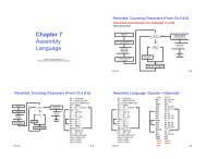
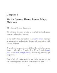
This Unit: <strong>Single</strong>-<strong>Cycle</strong> <strong>Datapath</strong><br />
CIS 371<br />
Computer Organization and Design<br />
App App App<br />
System software<br />
Mem CPU I/O<br />
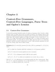
• <strong>Datapath</strong> storage elements<br />
• MIPS <strong>Datapath</strong><br />
• MIPS Control<br />
Unit 4: <strong>Single</strong>-<strong>Cycle</strong> <strong>Datapath</strong><br />
Based on slides by Prof. Amir Roth & Prof. Milo Martin<br />
CIS 371 (Martin): <strong>Single</strong>-<strong>Cycle</strong> <strong>Datapath</strong> 1<br />
CIS 371 (Martin): <strong>Single</strong>-<strong>Cycle</strong> <strong>Datapath</strong> 2<br />
Readings<br />
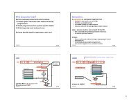
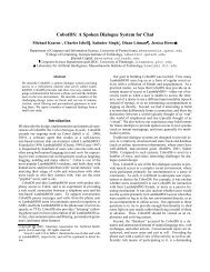
Motivation: Implementing an ISA<br />
• P&H<br />
• Sections 4.1 – 4.4<br />
fetch<br />
datapath<br />
PC<br />
Insn<br />
memory<br />
Register<br />
File<br />
Data<br />
Memory<br />
CIS 371 (Martin): <strong>Single</strong>-<strong>Cycle</strong> <strong>Datapath</strong> 3<br />
control<br />
• <strong>Datapath</strong>: performs computation (registers, ALUs, etc.)<br />
• ISA specific: can implement every insn (single-cycle: in one pass!)<br />
• Control: determines which computation is performed<br />
• Routes data through datapath (which regs, which ALU op)<br />
• Fetch: get insn, translate opcode into control<br />
• Fetch → Decode → Execute “cycle”<br />
CIS 371 (Martin): <strong>Single</strong>-<strong>Cycle</strong> <strong>Datapath</strong> 4
Two Types of Components<br />
Example <strong>Datapath</strong><br />
datapath<br />
fetch<br />
PC<br />
Insn<br />
memory<br />
Register<br />
File<br />
Data<br />
Memory<br />
control<br />
• Purely combinational: stateless computation<br />
• ALUs, muxes, control<br />
• Arbitrary Boolean functions<br />
• Combinational/sequential: storage<br />
• PC, insn/data memories, register file<br />
• Internally contain some combinational components<br />
CIS 371 (Martin): <strong>Single</strong>-<strong>Cycle</strong> <strong>Datapath</strong> 5<br />
CIS 371 (Martin): Digital Logic & Hardware Description 6<br />
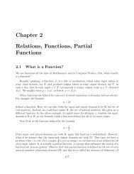
Register File<br />
RegDestVal<br />
RegSource1Val<br />
Register File<br />
RegSource2Val<br />
WE<br />
RD<br />
RS1 RS2<br />
<strong>Datapath</strong> Storage Elements<br />
• Register file: M N-bit storage words<br />
• Multiplexed input/output: data buses write/read “random” word<br />
• “Port”: set of buses for accessing a random word in array<br />
• Data bus (N-bits) + address bus (log 2 M-bits) + optional WE bit<br />
• P ports = P parallel and independent accesses<br />
• MIPS integer register file<br />
• 32 32-bit words, two read ports + one write port (why?)<br />
CIS 371 (Martin): <strong>Single</strong>-<strong>Cycle</strong> <strong>Datapath</strong> 7 CIS 371 (Martin): <strong>Single</strong>-<strong>Cycle</strong> <strong>Datapath</strong> 8
Decoder<br />
• Decoder: converts binary integer to “1-hot” representation<br />
• Binary representation of 0…2 N –1: N bits<br />
• 1 hot representation of 0…2 N –1: 2 N bits<br />
• J represented as J th bit 1, all other bits zero<br />
• Example below: 2-to-4 decoder<br />
B[0]<br />
B[1]<br />
1H[0]<br />
Decoder in Verilog (1 of 2)<br />
module decoder_2_to_4 (binary_in, onehot_out);!<br />
input [1:0] binary_in; !<br />
output [3:0] onehot_out;!<br />
assign onehot_out[0] = (~binary_in[0] & ~binary_in[1]);!<br />
assign onehot_out[1] = (~binary_in[0] & binary_in[1]);!<br />
assign onehot_out[2] = (binary_in[0] & ~binary_in[1]);!<br />
assign onehot_out[3] = (binary_in[0] & binary_in[1]);!<br />
endmodule!<br />
1H[1]<br />
1H[2]<br />
B<br />
1H<br />
• Is there a simpler way?<br />
1H[3]<br />
CIS 371 (Martin): <strong>Single</strong>-<strong>Cycle</strong> <strong>Datapath</strong> 9<br />
CIS 371 (Martin): <strong>Single</strong>-<strong>Cycle</strong> <strong>Datapath</strong> 10<br />
Decoder in Verilog (2 of 2)<br />
Register File Interface<br />
module decoder_2_to_4 (binary_in, onehot_out);!<br />
input [1:0] binary_in; !<br />
output [3:0] onehot_out;!<br />
assign onehot_out[0] = (binary_in == 2’d0);!<br />
assign onehot_out[1] = (binary_in == 2’d1);!<br />
assign onehot_out[2] = (binary_in == 2’d2);!<br />
assign onehot_out[3] = (binary_in == 2’d3);!<br />
endmodule!<br />
RDestVal<br />
RSrc2Val<br />
RSrc1Val<br />
• How is “a == b“ implemented for vectors?<br />
• |(a ^ b) (this is an “and” reduction of bitwise “a xor b”)<br />
• When one of the inputs to “==“ is a constant<br />
• Simplifies to simpler inverter on bits with “one” in constant<br />
• Exactly what was on previous slide!<br />
• Inputs:<br />
• RS1, RS2 (reg. sources to read), RD (reg. destination to write)<br />
• WE (write enable), RDestVal (value to write)<br />
• Outputs: RSrc1Val, RSrc2Val (value of RS1 & RS2 registers)<br />
CIS 371 (Martin): <strong>Single</strong>-<strong>Cycle</strong> <strong>Datapath</strong> 11 CIS 371 (Martin): <strong>Single</strong>-<strong>Cycle</strong> <strong>Datapath</strong> 12<br />
WE<br />
RD<br />
RS2<br />
RS1
Register File: Four Registers<br />
Add a Read Port<br />
RSrc1Val<br />
• Register file with four registers<br />
• Output of each register into 4to1 mux (RSrc1Val)<br />
• RS1 is select input of RSrc1Val mux<br />
RS1<br />
CIS 371 (Martin): <strong>Single</strong>-<strong>Cycle</strong> <strong>Datapath</strong> 13<br />
CIS 371 (Martin): <strong>Single</strong>-<strong>Cycle</strong> <strong>Datapath</strong> 14<br />
Add Another Read Port<br />
Add a Write Port<br />
RSrc2Val<br />
RDestVal<br />
RSrc2Val<br />
RSrc1Val<br />
RSrc1Val<br />
RS2<br />
RS1<br />
• Output of each register into another 4to1 mux (RSrc2Val)<br />
• RS2 is select input of RSrc2Val mux<br />
WE<br />
RD<br />
• Input RegDestVal into each register<br />
• Enable only one register’s WE: (Decoded RD) & (WE)<br />
• What if we needed two write ports?<br />
RS2<br />
RS1<br />
CIS 371 (Martin): <strong>Single</strong>-<strong>Cycle</strong> <strong>Datapath</strong> 15<br />
CIS 371 (Martin): <strong>Single</strong>-<strong>Cycle</strong> <strong>Datapath</strong> 16
Register File Interface (Verilog)<br />
module regfile4(rs1, rs1val, rs2, rs2val, rd, rdval, we, rst, clk);!<br />
parameter n = 1; !<br />
input [1:0] rs1, rs2, rd; !<br />
input we, rst, clk;!<br />
input [n-1:0] rdval; !<br />
output [n-1:0] rs1val, rs2val;!<br />
…!<br />
endmodule!<br />
Register File Interface (Verilog)<br />
module regfile4(rs1, rs1val, rs2, rs2val, rd, rdval, we, rst, clk);!<br />
input [1:0] rs1, rs2, rd; !<br />
input we, rst, clk;!<br />
input [15:0] rdval; !<br />
output [15:0] rs1val, rs2val;!<br />
• Building block modules:<br />
• module register (out, in, wen, rst, clk);!<br />
• module decoder_2_to_4 (binary_in, onehot_out)!<br />
• module Nbit_mux4to1 (sel, a, b, c, d, out); !<br />
endmodule!<br />
• Warning: this code not tested, may contain typos, do not blindly trust!<br />
CIS 371 (Martin): <strong>Single</strong>-<strong>Cycle</strong> <strong>Datapath</strong> 17<br />
CIS 371 (Martin): <strong>Single</strong>-<strong>Cycle</strong> <strong>Datapath</strong> 18<br />
[intentionally blank]<br />
[intentionally blank]<br />
CIS 371 (Martin): <strong>Single</strong>-<strong>Cycle</strong> <strong>Datapath</strong> 19<br />
CIS 371 (Martin): <strong>Single</strong>-<strong>Cycle</strong> <strong>Datapath</strong> 20
Register File Interface (Verilog)<br />
module regfile4(rs1, rs1val, rs2, rs2val, rd, rdval, we, rst, clk);!<br />
parameter n = 1; !<br />
input [1:0] rs1, rs2, rd; !<br />
input we, rst, clk;!<br />
input [n-1:0] rdval; !<br />
output [n-1:0] rs1val, rs2val;!<br />
Register File: Four Registers (Verilog)<br />
module regfile4(rs1, rs1val, rs2, rs2val, rd, rdval, we, rst, clk);!<br />
parameter n = 1; !<br />
input [1:0] rs1, rs2, rd; !<br />
input we, rst, clk;!<br />
input [n-1:0] rdval; !<br />
output [n-1:0] rs1val, rs2val;!<br />
wire [n-1:0] r0v, r1v, r2v, r3v;!<br />
Nbit_reg #(n) r0 (r0v, , , rst, clk);!<br />
Nbit_reg #(n) r1 (r1v, , , rst, clk);!<br />
Nbit_reg #(n) r2 (r2v, , , rst, clk);!<br />
Nbit_reg #(n) r3 (r3v, , , rst, clk);!<br />
endmodule!<br />
• Warning: this code not tested, may contain typos, do not blindly trust!<br />
CIS 371 (Martin): <strong>Single</strong>-<strong>Cycle</strong> <strong>Datapath</strong> 21<br />
endmodule!<br />
• Warning: this code not tested, may contain typos, do not blindly trust!<br />
CIS 371 (Martin): <strong>Single</strong>-<strong>Cycle</strong> <strong>Datapath</strong> 22<br />
Add a Read Port (Verilog)<br />
module regfile4(rs1, rs1val, rs2, rs2val, rd, rdval, we, rst, clk);!<br />
parameter n = 1; !<br />
input [1:0] rs1, rs2, rd; !<br />
input we, rst, clk;!<br />
input [n-1:0] rdval; !<br />
output [n-1:0] rs1val, rs2val;!<br />
wire [n-1:0] r0v, r1v, r2v, r3v;!<br />
Add Another Read Port (Verilog)<br />
module regfile4(rs1, rs1val, rs2, rs2val, rd, rdval, we, rst, clk);!<br />
parameter n = 1; !<br />
input [1:0] rs1, rs2, rd; !<br />
input we, rst, clk;!<br />
input [n-1:0] rdval; !<br />
output [n-1:0] rs1val, rs2val;!<br />
wire [n-1:0] r0v, r1v, r2v, r3v;!<br />
Nbit_reg #(n) r0 (r0v, , , rst, clk);!<br />
Nbit_reg #(n) r1 (r1v, , , rst, clk);!<br />
Nbit_reg #(n) r2 (r2v, , , rst, clk);!<br />
Nbit_reg #(n) r3 (r3v, , , rst, clk);!<br />
Nbit_mux4to1 #(n) mux1 (rs1, r0v, r1v, r2v, r3v, rs1val);!<br />
endmodule!<br />
• Warning: this code not tested, may contain typos, do not blindly trust!<br />
CIS 371 (Martin): <strong>Single</strong>-<strong>Cycle</strong> <strong>Datapath</strong> 23<br />
Nbit_reg #(n) r0 (r0v, , , rst, clk);!<br />
Nbit_reg #(n) r1 (r1v, , , rst, clk);!<br />
Nbit_reg #(n) r2 (r2v, , , rst, clk);!<br />
Nbit_reg #(n) r3 (r3v, , , rst, clk);!<br />
Nbit_mux4to1 #(n) mux1 (rs1, r0v, r1v, r2v, r3v, rs1val);!<br />
Nbit_mux4to1 #(n) mux2 (rs2, r0v, r1v, r2v, r3v, rs2val);!<br />
endmodule<br />
• Warning: this code not tested, may contain typos, do not blindly trust!<br />
CIS 371 (Martin): <strong>Single</strong>-<strong>Cycle</strong> <strong>Datapath</strong> 24
Add a Write Port (Verilog)<br />
module regfile4(rs1, rs1val, rs2, rs2val, rd, rdval, we, rst, clk);!<br />
parameter n = 1; !<br />
input [1:0] rs1, rs2, rd; !<br />
input we, rst, clk;!<br />
input [n-1:0] rdval; !<br />
output [n-1:0] rs1val, rs2val;!<br />
wire [n-1:0] r0v, r1v, r2v, r3v;!<br />
wire [3:0] rd_select; !<br />
decoder_2_to_4 dec (rd, rd_select);!<br />
Nbit_reg #(n) r0 (r0v, rdval, rd_select[0] & we, rst, clk);!<br />
Nbit_reg #(n) r1 (r1v, rdval, rd_select[1] & we, rst, clk);!<br />
Nbit_reg #(n) r2 (r2v, rdval, rd_select[2] & we, rst, clk);!<br />
Nbit_reg #(n) r3 (r3v, rdval, rd_select[3] & we, rst, clk);!<br />
Nbit_mux4to1 #(n) mux1 (rs1, r0v, r1v, r2v, r3v, rs1val);!<br />
Nbit_mux4to1 #(n) mux2 (rs2, r0v, r1v, r2v, r3v, rs2val);!<br />
endmodule!<br />
• Warning: this code not tested, may contain typos, do not blindly trust!<br />
CIS 371 (Martin): <strong>Single</strong>-<strong>Cycle</strong> <strong>Datapath</strong> 25<br />
Final Register File (Verilog)<br />
module regfile4(rs1, rs1val, rs2, rs2val, rd, rdval, we, rst, clk);!<br />
parameter n = 1; !<br />
input [1:0] rs1, rs2, rd; !<br />
input we, rst, clk;!<br />
input [n-1:0] rdval; !<br />
output [n-1:0] rs1val, rs2val;!<br />
wire [n-1:0] r0v, r1v, r2v, r3v;!<br />
Nbit_reg #(n) r0 (r0v, rdval, rd == 2`d0 & we, rst, clk);!<br />
Nbit_reg #(n) r1 (r1v, rdval, rd == 2`d1 & we, rst, clk);!<br />
Nbit_reg #(n) r2 (r2v, rdval, rd == 2`d2 & we, rst, clk);!<br />
Nbit_reg #(n) r3 (r3v, rdval, rd == 2`d3 & we, rst, clk);!<br />
Nbit_mux4to1 #(n) mux1 (rs1, r0v, r1v, r2v, r3v, rs1val);!<br />
Nbit_mux4to1 #(n) mux2 (rs2, r0v, r1v, r2v, r3v, rs2val);!<br />
endmodule!<br />
• Warning: this code not tested, may contain typos, do not blindly trust!<br />
CIS 371 (Martin): <strong>Single</strong>-<strong>Cycle</strong> <strong>Datapath</strong> 26<br />
Another Useful Component: Memory<br />
DATAIN<br />
DATAOUT<br />
ADDRESS<br />
Memory<br />
WE<br />
• Register file: M N-bit storage words<br />
• Few words (< 256), many ports, dedicated read and write ports<br />
• Memory: M N-bit storage words, yet not a register file<br />
• Many words (> 1024), few ports (1, 2), shared read/write ports<br />
• Leads to different implementation choices<br />
• Lots of circuit tricks and such<br />
• Larger memories typically only 6 transistors per bit<br />
• In Verilog? We’ll give you the code for large memories<br />
CIS 371 (Martin): <strong>Single</strong>-<strong>Cycle</strong> <strong>Datapath</strong> 27<br />
MIPS <strong>Datapath</strong><br />
CIS 371 (Martin): <strong>Single</strong>-<strong>Cycle</strong> <strong>Datapath</strong> 28
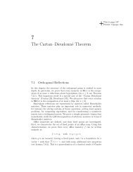
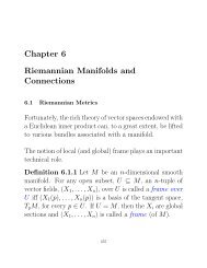
Unified vs Split Memory Architecture<br />
datapath<br />
<strong>Datapath</strong> for MIPS ISA<br />
• MIPS: 32-bit instructions, registers are $0, $2… $31<br />
PC<br />
fetch<br />
Register<br />
File<br />
control<br />
Insn/Data Memory<br />
• Consider only the following instructions<br />
add $1,$2,$3 $1 = $2 + $3 (add)<br />
addi $1,$2,3 $1 = $2 + 3 (add immed)<br />
lw $1,4($3) $1 = Memory[4+$3] (load)<br />
sw $1,4($3) Memory[4+$3] = $1 (store)<br />
beq $1,$2,PC_relative_target (branch equal)<br />
j absolute_target (unconditional jump)<br />
• Unified architecture: unified insn/data memory<br />
• “Harvard” architecture: split insn/data memories<br />
CIS 371 (Martin): <strong>Single</strong>-<strong>Cycle</strong> <strong>Datapath</strong> 29<br />
• Why only these?<br />
• Most other instructions are the same from datapath viewpoint<br />
• The one’s that aren’t are left for you to figure out<br />
CIS 371 (Martin): <strong>Single</strong>-<strong>Cycle</strong> <strong>Datapath</strong> 30<br />
Start With Fetch<br />
First Instruction: add<br />
+<br />
4<br />
+<br />
4<br />
P<br />
C<br />
Insn<br />
Mem<br />
P<br />
C<br />
Insn<br />
Mem<br />
Register<br />
File<br />
s1 s2 d<br />
• PC and instruction memory (split insn/data architecture, for now)<br />
• A +4 incrementer computes default next instruction PC<br />
• How would Verilog for this look given insn memory as interface?<br />
CIS 371 (Martin): <strong>Single</strong>-<strong>Cycle</strong> <strong>Datapath</strong> 31<br />
• Add register file<br />
• Add arithmetic/logical unit (ALU)<br />
CIS 371 (Martin): <strong>Single</strong>-<strong>Cycle</strong> <strong>Datapath</strong> 32
Wire Select in Verilog<br />
Second Instruction: addi<br />
• How to rip out individual fields of an insn? Wire select<br />
wire [31:0] insn;!<br />
wire [5:0] op = insn[31:26];!<br />
wire [4:0] rs = insn[25:21];!<br />
wire [4:0] rt = insn[20:16];!<br />
wire [4:0] rd = insn[15:11];!<br />
wire [4:0] sh = insn[10:6];!<br />
wire [5:0] func = insn[5:0];!<br />
P<br />
C<br />
+<br />
4<br />
Insn<br />
Mem<br />
Register<br />
File<br />
s1 s2 d<br />
S<br />
X<br />
• Destination register can now be either Rd or Rt<br />
• Add sign extension unit and mux into second ALU input<br />
CIS 371 (Martin): <strong>Single</strong>-<strong>Cycle</strong> <strong>Datapath</strong> 33 CIS 371 (Martin): <strong>Single</strong>-<strong>Cycle</strong> <strong>Datapath</strong> 34<br />
Verilog Wire Concatenation<br />
• Recall two Verilog constructs<br />
• Wire concatenation: {bus0, bus1, … , busn}!<br />
• Wire repeat: {repeat_x_times{w0}}!<br />
Third Instruction: lw<br />
+<br />
4<br />
• How do you specify sign extension? Wire concatenation<br />
wire [31:0] insn;!<br />
wire [15:0] imm16 = insn[15:0];!<br />
wire [31:0] sximm16 = {{16{imm16[15]}}, imm16};!<br />
P<br />
C<br />
Insn<br />
Mem<br />
Register<br />
File<br />
s1 s2 d<br />
S<br />
X<br />
a<br />
Data<br />
d<br />
Mem<br />
• Add data memory, address is ALU output<br />
• Add register write data mux to select memory output or ALU output<br />
CIS 371 (Martin): <strong>Single</strong>-<strong>Cycle</strong> <strong>Datapath</strong> 35 CIS 371 (Martin): <strong>Single</strong>-<strong>Cycle</strong> <strong>Datapath</strong> 36
Fourth Instruction: sw<br />
Fifth Instruction: beq<br />
+<br />
4<br />
+<br />
4<br />
What Is Control?<br />
+<br />
4<br />
Example: Control for beq<br />
How Is Control Implemented?<br />
+<br />
4<br />
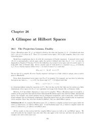
Control Implementation: Logic<br />
• Real machines have 100+ insns 300+ control signals<br />
• 30,000+ control bits (~4KB)<br />
– Not huge, but hard to make faster than datapath (important!)<br />
• Alternative: logic gates or “random logic” (unstructured)<br />
opcode<br />
• Exploits the observation: many signals have few 1s or few 0s<br />
• Example: random logic control for 6-insn MIPS datapath<br />
add<br />
addi<br />
lw<br />
sw<br />
beq<br />
j<br />
Control Logic in Verilog<br />
wire [31:0] insn;!<br />
wire [5:0] func = insn[5:0]!<br />
wire [5:0] opcode = insn[31:26];!<br />
wire is_add = ((opcode == 6’h00) & (func == 6’h20));!<br />
wire is_addi = (opcode == 6’h0F);!<br />
wire is_lw = (opcode == 6’h23);!<br />
wire is_sw = (opcode == 6’h2A);!<br />
wire ALUinB = is_addi | is_lw | is_sw; !<br />
wire Rwe = is_add | is_addi | is_lw;!<br />
wire Rwd = is_lw;!<br />
wire Rdst = ~is_add;!<br />
wire DMwe = is_sw;!<br />
opcode<br />
add<br />
addi<br />
lw<br />
sw<br />
BR JP DMwe Rwe Rwd Rdst ALUop<br />
ALUinB<br />
CIS 371 (Martin): <strong>Single</strong>-<strong>Cycle</strong> <strong>Datapath</strong> 49<br />
DMwe<br />
Rwe<br />
Rwd Rdst<br />
CIS 371 (Martin): <strong>Single</strong>-<strong>Cycle</strong> <strong>Datapath</strong> 50<br />
ALUinB<br />
<strong>Single</strong>-<strong>Cycle</strong> <strong>Datapath</strong> Performance<br />
+<br />
4<br />
Foreshadowing: Pipelined <strong>Datapath</strong><br />
Summary<br />
+<br />
4<br />
PC<br />
PC<br />