TurboCAD Pro V17.2 Sprockets Chain SAMPLE - Textual Creations
TurboCAD Pro V17.2 Sprockets Chain SAMPLE - Textual Creations
TurboCAD Pro V17.2 Sprockets Chain SAMPLE - Textual Creations

Create successful ePaper yourself
Turn your PDF publications into a flip-book with our unique Google optimized e-Paper software.
Donald B. Cheke<br />
www.textualcreations.ca<br />
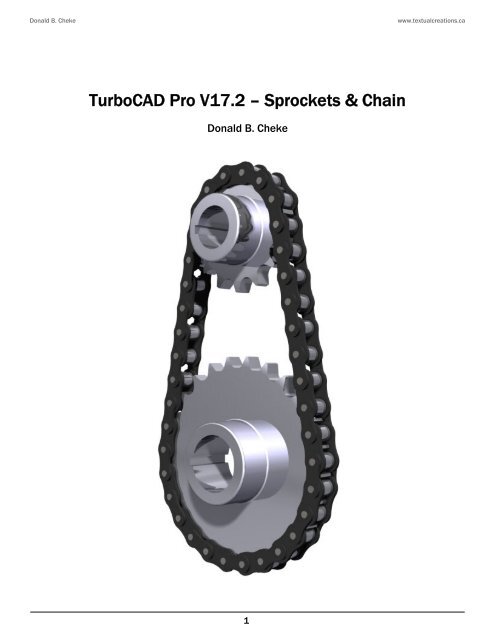
<strong>TurboCAD</strong> <strong>Pro</strong> <strong>V17.2</strong> – <strong>Sprockets</strong> & <strong>Chain</strong><br />
Donald B. Cheke<br />
1
Donald B. Cheke<br />
Copyright © 2010 Donald B. Cheke<br />
www.textualcreations.ca<br />
<strong>TurboCAD</strong> is a registered trademark of IMSI/Design.<br />
Published by:<br />
Donald B. Cheke<br />
Saskatoon, SK Canada<br />
Visit: www.textualcreations.ca<br />
All rights reserved<br />
No part of this document may be reproduced, copied, stored on a retrieval system or transmitted in any<br />
form without written permission from the author. The purchaser may, however, print one copy of the<br />
document to paper and may make one backup copy of the downloaded material for personal safe<br />
keeping.<br />
Limitation of Liability<br />
While every effort has been taken in the preparation and the writing of this document the author<br />
assumes no responsibility for errors and/or omissions nor for the uses of the material and the decisions<br />
based on such use. No warranties are made, express or implied with regard to either the contents of the<br />
document, its merchant ability or fitness for a particular purpose. The author should not be liable for<br />
direct, indirect, special, incidental or consequential damages arising out of the use or inability to use the<br />
contents of this document.<br />
Special Note<br />
All of the work presented within this tutorial is based on <strong>TurboCAD</strong> <strong>Pro</strong> <strong>V17.2</strong>. Although users of previous<br />
versions are welcome to try the tutorial it cannot be stated what results will be achieved. Many changes,<br />
some subtle and others not so subtle, are made with each program revision. Although many steps and<br />
directions would be generic some may not be. The same can be said for tools between versions. Older<br />
versions may not have the same tools as <strong>Pro</strong> <strong>V17.2</strong> and if the same tools are available the tools<br />
themselves may have been revised and hence, work in a different manner than they previously did.<br />
2
Donald B. Cheke<br />
www.textualcreations.ca<br />
Table of Contents<br />
Table of Contents ......................................................................................................................................................... 3<br />
Introduction .................................................................................................................................................................. 4<br />
Setup .............................................................................................................................................................................. 6<br />
2D Sprocket Layout ................................................................................................................................................... 21<br />
2D Sprocket <strong>Pro</strong>files to 3D <strong>Sprockets</strong> .................................................................................................................... 44<br />
2D <strong>Chain</strong> Link Layout ................................................................................................................................................ 64<br />
2D Link <strong>Pro</strong>files to 3D Links .................................................................................................................................... 68<br />
Materials Application ................................................................................................................................................ 83<br />
Named View ................................................................................................................................................................ 89<br />
Render Scene Luminance ........................................................................................................................................ 91<br />
Render Scene Environment ..................................................................................................................................... 95<br />
Saving the Rendered Image..................................................................................................................................... 98<br />
Appendix – An Important Note about <strong>TurboCAD</strong> Materials ............................................................................. 101<br />
3
Donald B. Cheke<br />
www.textualcreations.ca<br />
Introduction<br />
Laying out sprockets and chains within <strong>TurboCAD</strong> can certainly seem a daunting task for any new user.<br />
But like most things in the world of CAD, it is manageable when someone takes the time to explain the<br />
process.<br />
Within this tutorial the reader will be led through each keystroke to produce all components of the<br />
sprockets and chain that are illustrated on the cover of the tutorial. The reader will learn how to set up<br />
their drawing, how to draw the required 2D profiles and use those 2D profiles to create the 3D<br />
components. The reader will also learn how to insert standard lighting and how utilize render scene<br />
luminance. The reader will learn how to establish a render scene environment and the reader will learn<br />
how to render their drawing and save it in a high resolution image format.<br />
This tutorial is in no way intended to teach the fundamentals of sprocket and chain design but rather it is<br />
intended to teach the use of some of the tools that <strong>TurboCAD</strong> has to offer and to introduce the new user<br />
to a drawing methodology. The author feels confident that the techniques outlined within the tutorial can<br />
help lay the foundation for future successful <strong>TurboCAD</strong> drawing and illustration for even the newest user.<br />
As with any technically advanced software, the user is generally faced with a steep learning curve. It is<br />
the hope of the author that the money and time spent working through a <strong>Textual</strong> <strong>Creations</strong> tutorial will<br />
help ease the learning and allow the reader to come away feeling confident that they made a wise<br />
decision.<br />
This tutorial will assume that the reader has the Platinum edition of <strong>TurboCAD</strong> <strong>Pro</strong> <strong>V17.2</strong> with its extra<br />
architectural and mechanical tools, although no Platinum specific tools are used that the author is aware<br />
of.<br />
There are many ways to approach a project and it is likely that each person using the program would<br />
proceed in very different ways, so be open to alternative methods as experience builds. What is<br />
important is that the user becomes familiar with the objects that they wish to model and begin to look at<br />
them in a different way than they might otherwise do. What primitive shapes make up the whole? What<br />
will be required of these primitive shapes early in the drawing and how will this affect needs further<br />
along? What component or components should be started with? Many questions can only be answered<br />
through experience, but hopefully some of them will be answered by the time the beginner has worked<br />
through this tutorial. There is a great deal covered in this tutorial and the author urges the beginner to be<br />
patient, to read very carefully and to take the time necessary to do a good job. Try to enjoy the process as<br />
much as you will enjoy the final results.<br />
This tutorial assumes that the beginner has studied the desktop to some degree and can locate most of<br />
the tools. Since there are endless desktop configurations that can be set up in <strong>TurboCAD</strong> the author has<br />
opted to illustrate the required tools with the Office 2000 user interface, and the default toolbars in their<br />
undocked format (Office 2000 theme).<br />
4
Donald B. Cheke<br />
www.textualcreations.ca<br />
Please remember that any supplied images and files are for use within the tutorial only and may not be<br />
shared or sold to others.<br />
Place tutorial images in a permanent location on the hard drive.<br />
5
Donald B. Cheke<br />
2D Sprocket Layout<br />
www.textualcreations.ca<br />
Switch to Front view.<br />
Select Plane by Active View from the Workplane toolbar.<br />
Scroll in so the grid is visible on screen.<br />
The profiles for a 14 tooth upper sprocket and a 25 tooth lower sprocket will now be created, beginning<br />
with the lower sprocket. The image below illustrates what is being worked towards. Once complete, a<br />
single tooth from each set will be traced, extruded and then radial copied.<br />
Select the Polygon tool from the Line toolbar.<br />
Select Sienna from the color dropdown menu on the <strong>Pro</strong>perty toolbar.<br />
Tab into the Inspector Bar and enter 25 in the Sides field. Press Enter.<br />
21
Donald B. Cheke<br />
Press Esc to exit the Rubber Stamp tool.<br />
www.textualcreations.ca<br />
Press Ctrl + K to open the Select by Colors dialogue. Select By Layer (result of the grouping) and click OK.<br />
Select the Mirror Copy tool from the Copy toolbar.<br />
V SEKE snap the lower point of the upper sprocket segment profile to define the first point of the<br />
mirroring line. Press and hold the Shift key down. Move the cursor downward a short distance and then<br />
left mouse click to define the second point of the mirroring line. Release the Shift key. In progress below.<br />
Turn off the 2D layer.<br />
2D Sprocket <strong>Pro</strong>files to 3D <strong>Sprockets</strong><br />
Switch to Isometric SE view.<br />
Select the Simple Extrude tool from the 3D Objects toolbar.<br />
Select the Two sided extrude option.<br />
44
Donald B. Cheke<br />
www.textualcreations.ca<br />
Select the upper profile as the object to extrude. Tab into the Inspector Bar and enter .25 in the Height<br />
field. Press Enter to extrude .25 in both directions.<br />
Select the lower profile as the object to extrude. Tab into the Inspector Bar and enter .25 in the Height<br />
field. Press Enter to extrude .25 in both directions.<br />
Press Ctrl + K to open the Select by Colors dialogue. Select Blue and click OK.<br />
Assign the selection to the 2D layer.<br />
Select the upper sprocket segment.<br />
Select the Radial Copy tool from the Copy toolbar.<br />
V SEKE snap the lower forward vertex to define the center of the arc. In progress below.<br />
Tab into the Inspector Bar and enter 14 in the Sets field. Press Enter.<br />
Select the lower sprocket segment.<br />
Select the Radial Copy tool from the Copy toolbar.<br />
V SEKE snap the upper forward vertex to define the center of the arc. In progress below.<br />
45
Donald B. Cheke<br />
www.textualcreations.ca<br />
Select the central .5 inch circle as the object to extrude. Tab into the Inspector Bar and enter .255 in the<br />
Height field. Press Enter.<br />
Select the right .5 inch circle as the object to extrude. Tab into the Inspector Bar and enter .255 in the<br />
Height field. Press Enter.<br />
Press the Space Bar to exit the tool.<br />
Select Workplane by Origin from the Workplane toolbar.<br />
Place the cursor by the edge of the roller, as indicated in the picture below, and C SEKE snap to define<br />
the new workplane. In progress below.<br />
Select the Blue link profile and then select Place on Workplane from the Format menu at the top of the<br />
<strong>TurboCAD</strong> desktop.<br />
Select the Simple Extrude tool from the 3D Objects toolbar.<br />
Disengage the Two sided extrude option.<br />
Select the Blue link profile as the object to extrude. Tab into the Inspector Bar and enter .085 in the<br />
Height field. Press Enter.<br />
69
Donald B. Cheke<br />
www.textualcreations.ca<br />
Press the Space Bar to exit the tool.<br />
Select Workplane by Origin from the Workplane toolbar.<br />
Place the cursor by the edge of the last extrusion, as indicated in the picture below, and C SEKE snap to<br />
define the new workplane. In progress below.<br />
Select the Forest Green link profile and then select Place on Workplane from the Format menu at the top<br />
of the <strong>TurboCAD</strong> desktop.<br />
Select the Simple Extrude tool from the 3D Objects toolbar.<br />
Select the Forest Green link profile as the object to extrude. Tab into the Inspector Bar and enter .085 in<br />
the Height field. Press Enter.<br />
Engage the Two sided extrude option.<br />
Select the left .2 inch red circle as the object to extrude. Tab into the Inspector Bar and enter .45 in the<br />
Height field. Press Enter.<br />
Select the central .2 inch red circle as the object to extrude. Tab into the Inspector Bar and enter .45 in<br />
the Height field. Press Enter.<br />
70
Donald B. Cheke<br />
www.textualcreations.ca<br />
Click OK to exit the Render Scene Environment Editor and click OK to exit the Drawing Setup dialogue.<br />
Allow the scene to rerender (13 seconds on the author's off the shelf HP).<br />
Saving the Rendered Image<br />
This render will now be saved.<br />
The author has found that saving as a high resolution JPG or BMP produces excellent results. If a smaller<br />
image is required afterward, resizing with an image editor and saving in JPG format retains the excellent<br />
results.<br />
98