

compact av sender - Philex
compact av sender - Philex
compact av sender - Philex

Create successful ePaper yourself
Turn your PDF publications into a flip-book with our unique Google optimized e-Paper software.
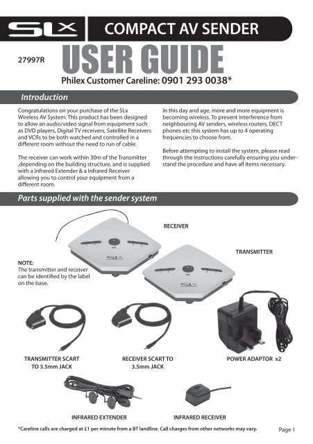
27997R<br />
Introduction<br />
COMPACT AV SENDER<br />
USER GUIDE<br />
<strong>Philex</strong> Customer Careline: 0901 293 0038*<br />
Congratulations on your purchase of the SLx<br />
Wireless AV System. This product has been designed<br />
to allow an audio/video signal from equipment such<br />
as DVD players, Digital TV receivers, Satellite Receivers<br />
and VCRs to be both watched and controlled in a<br />
different room without the need to run of cable.<br />
The receiver can work within 30m of the Transmitter<br />
,depending on the building structure, and is supplied<br />
with a Infrared Extender & a Infrared Receiver<br />
allowing you to control your equipment from a<br />
different room.<br />
Parts supplied with the <strong>sender</strong> system<br />
In this day and age, more and more equipment is<br />
becoming wireless. To prevent interference from<br />
neighbouring AV <strong>sender</strong>s, wireless routers, DECT<br />
phones etc this system has up to 4 operating<br />
frequencies to choose from.<br />
Before attempting to install the system, please read<br />
through the instructions carefully ensuring you understand<br />
the procedure and h<strong>av</strong>e all items necessary.<br />
RECEIVER<br />
NOTE:<br />
The transmitter and receiver<br />
can be identified by the label<br />
on the base.<br />
TRANSMITTER<br />
TRANSMITTER SCART<br />
TO 3.5mm JACK<br />
RECEIVER SCART TO<br />
3.5mm JACK<br />
POWER ADAPTOR x2<br />
INFRARED EXTENDER<br />
INFRARED RECEIVER<br />
*Careline calls are charged at £1 per minute from a BT landline. Call charges from other networks may vary. Page 1
IR-R<br />
Receiver connections & switches layout<br />
AV OUTPUT<br />
SOCKET<br />
Infrared ANTENNA<br />
IR-ANT<br />
Infrared<br />
RECEIVER SOCKET<br />
DC INPUT<br />
1 2 3 4<br />
CH<br />
2.4 GHz wireless video <strong>sender</strong><br />
ON OFF<br />
CHANNEL SELECT BUTTON<br />
ON/OFF SWITCH<br />
NOTE:<br />
Receiver can be identified by label under the unit<br />
2
IR-T<br />
Transmitter connections & switches layout<br />
AV INPUT<br />
SOCKET<br />
Infrared<br />
EYE EXTENDER SOCKET<br />
1 2 3 4<br />
CH<br />
2.4 GHz wireless video <strong>sender</strong><br />
ON OFF<br />
CHANNEL SELECT BUTTON<br />
NOTE:<br />
Transmitter can be identified by label under the unit<br />
ON/OFF SWITCH<br />
3
Getting the best reception<br />
• Both the AV Transmitter and Receiver units should<br />
be placed on flat, stable surfaces or wall mounted.<br />
• Fully extend the Infrared Antenna from<br />
the Receiver.<br />
Setting up your Transmitter and Receiver<br />
• Minimise the number of obstacles between<br />
the AV Transmitter and Receiver.<br />
CONNECTING THE RECEIVER<br />
(Bedroom/Kitchen etc.)<br />
1) Plug the 3.5mm jack end of the ‘Receiver Scart to<br />
3.5mm Jack Cable’ into the AV OUT socket on the<br />
Receiver. Ensure that the 3.5mm JACK is plugged<br />
all the way into the AV OUT socket.<br />
2) Plug the Scart end of the ‘Receiver Scart to 3.5mm<br />
Jack Cable’ into the Scart input on the television<br />
located in the receiving room - e.g. Kitchen or<br />
bedroom. (See Fig. 2)<br />
3) Connect one of the power adaptors to the DC input<br />
on the Receiver as shown in Fig. 2. Plug the power<br />
adaptor into a mains socket and switch the socket<br />
ON, the channel 1 LED shall now be lit. If the LED<br />
does not light up, switch the Receiver ON.<br />
INFRARED RECEIVER<br />
4) Position the Infrared RECEIVER on top/in front of<br />
your television or another location where there is a<br />
clear line of sight to the sitting location. (See Fig.1)<br />
CONNECTING THE TRANSMITTER<br />
(Main viewing room, e.g. Lounge)<br />
5) Plug the 3.5mm Jack end of the ‘Transmitter Scart<br />
to 3.5mm Jack Cable’ into the AV IN socket on the<br />
Transmitter. Ensure that the 3.5mm Jack is plugged<br />
all the way in to the AV IN socket.<br />
6) Plug the Scart end of the ‘Transmitter Scart to<br />
3.5mm jack cable’ into the Scart output socket on<br />
your AV source equipment (satellite receiver or VCR<br />
or DVD).<br />
7) Plug the Infrared Extender cable into the Infra Red<br />
Socket on the Transmitter as shown in Fig. 3.<br />
8) Position one of the Infrared Eyes on the Infrared<br />
Extender lead in front of the Infrared sensor window<br />
of your AV source equipment (satellite receiver or<br />
VCR or DVD). The Infrared sensor window on some<br />
satellite receivers is marked by this symbol .<br />
Make sure the curved surface of the Infrared Eye is<br />
facing the sensor window as shown in Fig. 4 and<br />
(For further tips on locating the Infrared sensor<br />
window see Troubleshooting section).<br />
9) Connect the remaining power adaptor to the DC<br />
input on the Transmitter as shown in Fig. 3.<br />
Plug the power adaptor into a mains socket and<br />
switch the socket ON, the channel 1 LED will now<br />
be lit. If the LED does not light up, switch<br />
the Transmitter ON.<br />
10) On top of both the Transmitter and Receiver is a<br />
channel selector, the channels are represented<br />
by indicator lights. Pressing the button toggles<br />
between the 4 channels. Ensure that the same<br />
channel indicator is lit on both the Transmitter<br />
and Receiver.<br />
Please NOTE:<br />
The channel selector on both the Transmitter<br />
and Receiver will revert to Channel 1 when they<br />
are switched off. When turning the Transmitter<br />
and Receiver back on you may need to re-select<br />
the correct channel.<br />
11) Select an appropriate AV channel on the receiving<br />
television. The television should now show the<br />
signal that the Transmitter is sending and if the<br />
infra red eye is properly positioned you will be able<br />
to control the AV source by pointing a compatible<br />
remote control at the AV Receiver.<br />
Fig. 1 -Positioning the Infrared Receiver<br />
Infrared Receiver<br />
Note: Attach with the adhesive pad supplied<br />
4
Fig. 2 - Receiver Connections Room 2<br />
SECOND TV (BEDROOM/KITCHEN etc.)<br />
INFRA-RED<br />
ANTENNA<br />
SCART INPUT<br />
INFRA-RED<br />
RECEIVER<br />
RECEIVER<br />
UNIT<br />
POWER<br />
ADAPTOR<br />
RECEIVER SCART TO<br />
3.5mm JACK<br />
Fig. 3 -Transmitter Connections Main Room<br />
INFRA-RED<br />
EXTENDER<br />
(see Fig. 3 for positioning)<br />
POWER<br />
ADAPTOR<br />
SAT, DVD, DVBT etc<br />
SCART OUTPUT<br />
TRANSMITTER<br />
UNIT<br />
TRANSMITTER SCART TO<br />
3.5mm JACK<br />
Fig. 4 -Positioning the Infra Red Eye<br />
SATELLITE<br />
Infra red eyes<br />
Make sure the curved surface of the infra<br />
red eye is facing the sensor window<br />
5
Troubleshooting<br />
PROBLEM CAUSE ACTION<br />
Problem Cause Action<br />
No Picture or Sound The Transmitter and receiver are set Set to identical channels<br />
to different channels<br />
(See step 6)<br />
Black and White<br />
(Monochrome Picture)<br />
Poor Picture Quality<br />
The Transmitter and/or Receiver are<br />
not powered<br />
The Transmitter and/or Receiver<br />
Leads are incorrectly fitted/reversed<br />
Transmitter and/or Receiver Units<br />
are reversed<br />
The equipment providing or<br />
receiving the AV signal are<br />
incorrectly setup<br />
Distance between the Transmitter<br />
and receiver is too far<br />
The equipment providing or<br />
receiving the AV signal is set to<br />
RGB, Component Video, SVHS S<br />
Video, DVI or HDMI<br />
Interference from Wireless<br />
Networking devices, microw<strong>av</strong>es<br />
ovens etc.<br />
Obstruction to signal<br />
Check the power switches on the<br />
unit(s) are both in the<br />
On position<br />
Check that the Mains Electrical<br />
power is switched on<br />
Check the 9 Volt Mains adaptors<br />
are fitted correctly (See Steps 3 & 9)<br />
Swap over both leads so the<br />
correct leads are used with the<br />
Receiver/Transmitter<br />
The leads are not inserted correctly,<br />
ensure that the scart plug has no<br />
bent pins and it making contact<br />
with the scart socket<br />
Swap over the Transmitter and<br />
Receiver units<br />
Check that the Transmitting and<br />
Receiving Equipment are powered<br />
up and providing a Scart Input and<br />
output signal<br />
Ensure that correct Scart input has<br />
been selected on the Receiving<br />
equipment<br />
Set the Scart output/input to<br />
Composite Video (CVBS) (See<br />
Equipment Suppliers Manual for<br />
how to set)<br />
Reduce the distance between the<br />
units or position the units for a<br />
better signal<br />
Set the Scart output/input to<br />
Composite Video (CVBS)<br />
(See Equipment Suppliers Manual<br />
for how to set)<br />
Change Transmitter/Receiver<br />
frequencies<br />
Place away from walk ways or walk<br />
through areas<br />
Place away from Thick walls,<br />
masonry or metalwork<br />
6
PROBLEM CAUSE ACTION<br />
All the <strong>av</strong>ailable scart<br />
sockets are being used<br />
Infra red remote control<br />
does not function<br />
Distance between the Transmitter<br />
and receiver is too far<br />
The Transmitter and receiver are set<br />
to different channels<br />
The equipment providing or receiving<br />
the AV signal is<br />
incorrectly set<br />
Equipment has insufficient scart<br />
sockets<br />
Infrared Eyes set up incorrectly<br />
Sunlight or high output lighting is<br />
blocking the Signal<br />
Incorrect Remote used<br />
Infra red Transmitter or receiver<br />
signal is obstructed<br />
Difficulty finding the Infra red sensor<br />
on the Transmitting Equipment<br />
(DVD, Satellite etc)<br />
Intermittent or no Infra red<br />
operation<br />
Cable Box which use IRDA Remote<br />
controls<br />
Reduce the distance between the<br />
units or position the units for a<br />
better signal<br />
Set to identical channels (See step<br />
10)<br />
The Leads are not inserted correctly,<br />
ensure that there are no bent<br />
pins in the scart plug and it making<br />
contact<br />
Purchase an unswitched scart splitter<br />
for the transmitting equipment<br />
and/or a switched scart selector for<br />
the receiving equipment<br />
Connect equipment using other<br />
connector type e.g. Coax flylead<br />
Infra red transmitting and/or<br />
receiving eyes are not positioned<br />
correctly (See Step 8)<br />
Block the excessive light<br />
Use Original or compatible Remote<br />
controls<br />
Remove obstruction and position<br />
the Infra red eyes for a better signal<br />
(See Figs 4 and 8) and use a second<br />
person aiming the remote control<br />
at the AV Receiver while the first<br />
person moves the Infra red eyes<br />
in front of the Transmitting Equipment<br />
Check that the Infra red leads are<br />
correctly inserted into the Infra red<br />
Socket(s)<br />
Check the remote works directly<br />
with the Transmitting equipment<br />
and that the batteries are not<br />
discharged<br />
Some cable boxes use an IRDA remote<br />
control system these will not<br />
work with you AV <strong>sender</strong> (Contact<br />
your Cable supplier to see if your<br />
box uses IRDA<br />
7
Customer support<br />
For further information or any queries please contact<br />
Customer Careline: 0901 293 0038<br />
Calls are charged at £1 per minute from a BT landline.<br />
Call charges from other networks may vary<br />
Technical Support: www.philex.com/support<br />
Declaration of conformity<br />
1856<br />
Declaration of Conformity <strong>av</strong>ailable at:<br />
www.philex.com/support<br />
Environmental policy<br />
Waste electrical products should not be disposed of with<br />
household waste. Please recycle where facilities exist.<br />
Check with your Local Authority for recycling advice.<br />
© <strong>Philex</strong> Electronic Ltd. 2010. V.1.2


![Freesat Installation kit [35.pdf] - Philex](https://img.yumpu.com/43505801/1/184x260/freesat-installation-kit-35pdf-philex.jpg?quality=85)

![(HD) Satellite kit [28260R_28261R_IM_1_3nonpaySlx.pdf] - Philex](https://img.yumpu.com/35201073/1/184x260/hd-satellite-kit-28260r-28261r-im-1-3nonpayslxpdf-philex.jpg?quality=85)

![48 element aerial Gold [27884LAB_IM_v1_5.pdf] - Philex](https://img.yumpu.com/29233381/1/188x260/48-element-aerial-gold-27884lab-im-v1-5pdf-philex.jpg?quality=85)
![7 Day Electronic Timer Switch [76933R_IM_V1_3.pdf] - Philex](https://img.yumpu.com/23209791/1/190x136/7-day-electronic-timer-switch-76933r-im-v1-3pdf-philex.jpg?quality=85)


