

TeSys U starter controlers Part 2 - Schneider Electric
TeSys U starter controlers Part 2 - Schneider Electric
TeSys U starter controlers Part 2 - Schneider Electric

Create successful ePaper yourself
Turn your PDF publications into a flip-book with our unique Google optimized e-Paper software.
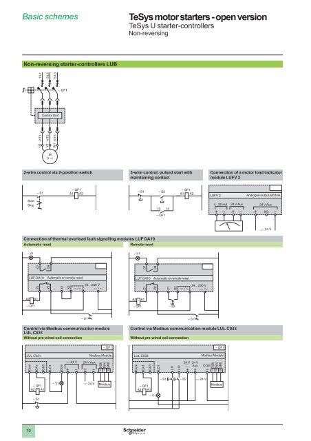
Basic schemes 1<br />
<strong>TeSys</strong> motor <strong>starter</strong>s - open version 1<br />
<strong>TeSys</strong> U <strong>starter</strong>-controllers<br />
Non-reversing<br />
1<br />
Non-reversing <strong>starter</strong>-controllers LUB<br />
1/L1<br />
3/L2<br />
5/L3<br />
2<br />
Control Unit<br />
3<br />
2/T1<br />
U1<br />
4/T2<br />
V1<br />
M<br />
3 a<br />
6/T3<br />
W1<br />
4<br />
2-wire control via 2-position switch<br />
3-wire control, pulsed start with<br />
maintaining contact<br />
Connection of a motor load indicator<br />
module LUFV 2<br />
A1<br />
A2<br />
A1<br />
A2<br />
LUFV 2<br />
Analogue output Module<br />
5<br />
Start<br />
Stop<br />
13 14<br />
4...20 mA<br />
24 V Aux<br />
24 V Aux<br />
NC<br />
6<br />
Connection of thermal overload fault signalling modules LUF DA10<br />
Automatic reset<br />
Remote reset<br />
– V1<br />
– V1<br />
07<br />
08<br />
07<br />
08<br />
LUF DA10<br />
Automatic or remote reset<br />
LUF DA10<br />
Automatic or remote reset<br />
7<br />
Z1<br />
Z2<br />
X1<br />
X2<br />
24…230 V<br />
Z1<br />
Z2<br />
X1<br />
X2<br />
24…230 V<br />
A2<br />
A1<br />
A2<br />
A1<br />
– QF1<br />
– QF1 – S2<br />
8<br />
– S1<br />
Control via Modbus communication module<br />
LUL C031<br />
Without pre-wired coil connection<br />
– S1<br />
Control via Modbus communication module LUL C033<br />
Without pre-wired coil connection<br />
9<br />
LUL C031<br />
Com<br />
OA1<br />
OA3<br />
LO1<br />
Com<br />
Modbus Module<br />
24 V Aux<br />
D(B)<br />
D(A)<br />
GND<br />
4<br />
5<br />
68<br />
LUL C033<br />
Com<br />
OA1<br />
OA3<br />
LO1<br />
LI1<br />
LI2<br />
24 V<br />
c<br />
24 Aux<br />
V<br />
Modbus Module<br />
COM<br />
D(B)<br />
D(A)<br />
GND<br />
4<br />
5<br />
68<br />
10<br />
A2<br />
A1<br />
Modbus<br />
A2<br />
A1<br />
– S1<br />
– S2<br />
Modbus<br />
70
Basic schemes (continued) 1<br />
<strong>TeSys</strong> motor <strong>starter</strong>s - open version 1<br />
<strong>TeSys</strong> U <strong>starter</strong>-controllers<br />
Non-reversing<br />
Non-reversing <strong>starter</strong> controllers LUB (continued)<br />
Control by communication modules ASILUF C5 and ASILUF C51<br />
Without pre-wired coil connection<br />
Without pre-wired coil connection<br />
With local control<br />
1<br />
ASILUF C5<br />
or ASILUF C51<br />
Com<br />
OA1<br />
OA3<br />
AS-Interface Module<br />
AS-Interface<br />
ASILUF C5<br />
or ASILUF C51<br />
Com<br />
OA1<br />
OA3<br />
AS-Interface Module<br />
AS-Interface<br />
2<br />
A2<br />
A1<br />
AS-Interface line<br />
Normal<br />
Adjustment<br />
AS-Interface line<br />
3<br />
A2<br />
A1<br />
With pre-wired coil connection LU9B N11C<br />
Without pre-wired coil connection<br />
With local control<br />
4<br />
ASILUF C5<br />
or ASILUF C51<br />
AS-Interface Module<br />
ASILUF C5<br />
or ASILUF C51<br />
AS-Interface Module<br />
LU9B N11C<br />
Pre wired coil<br />
AS-Interface<br />
Com<br />
OA1<br />
OA3<br />
AS-Interface<br />
5<br />
AS-Interface line<br />
AS-Interface line<br />
A2<br />
A1<br />
Adjustment<br />
Normal<br />
6<br />
Without pre-wired coil connection<br />
With multifunction control unit LUCM<br />
7<br />
ASILUF C5<br />
or ASILUF C51<br />
Com<br />
OA1<br />
OA3<br />
AS-Interface Module<br />
AS-Interface<br />
8<br />
A2<br />
A1<br />
AS-Interface line<br />
9<br />
LUCM<br />
24 V Aux<br />
Multifunction Control Unit<br />
RJ45<br />
D(B)<br />
D(A)<br />
GND<br />
4<br />
5<br />
68<br />
Bus Modbus<br />
RS 485<br />
10<br />
71
Basic schemes (continued) 1<br />
<strong>TeSys</strong> motor <strong>starter</strong>s - open version 1<br />
<strong>TeSys</strong> U <strong>starter</strong>-controllers<br />
Reversing<br />
1<br />
Reversing <strong>starter</strong>-controllers LUB<br />
2-wire control<br />
via 3-position switch<br />
3-wire control, pulsed start with maintaining contact<br />
2/T1<br />
U1<br />
2/T1<br />
V1<br />
4/T2<br />
4/T2<br />
W1<br />
1/L1<br />
3/L2<br />
5/L3<br />
LU2B<br />
Reverser Motor Controller<br />
LU2B<br />
Reverser Motor Controller<br />
2<br />
Control Unit<br />
A3<br />
B3<br />
A1<br />
B1<br />
A2<br />
A3<br />
Start<br />
forward running<br />
B3<br />
A1<br />
6/T3<br />
6/T3<br />
B1<br />
A2<br />
3<br />
forward running<br />
Stop<br />
reverse running<br />
Stop<br />
forward running<br />
and reverse<br />
running<br />
Stop<br />
forward running<br />
Start<br />
reverse running<br />
Stop<br />
reverse running<br />
4<br />
M<br />
3<br />
Control by communication modules ASILUF C5<br />
and ASILUF C51<br />
With pre-wired coil connection LU9M RC<br />
With multifunction control unit LUCM<br />
3-wire control, pulsed start with maintaining contact and limit switches<br />
5<br />
ASILUF C5<br />
or ASILUF C51<br />
AS-Interface Module<br />
LU2B<br />
Reverser Motor Controller<br />
LU9M RC<br />
Pre wired coil<br />
AS-Interface<br />
A3<br />
B3<br />
A1<br />
B1<br />
A2<br />
6<br />
AS-Interface line<br />
Limit switch<br />
Stop<br />
forward running<br />
forward running<br />
Start<br />
forward running<br />
7<br />
LUCM<br />
24 V Aux<br />
Multifunction Control Unit<br />
D(B)<br />
D(A)<br />
GND<br />
4<br />
5<br />
68<br />
Bus Modbus<br />
RS 485<br />
Stop forward<br />
running<br />
and reverse<br />
running<br />
Limit switch<br />
Stop<br />
reverse running<br />
reverse running<br />
Start<br />
reverse running<br />
8<br />
Control by communication modules ASILUF C5<br />
and ASILUF C51<br />
Without pre-wired coil connection<br />
With running direction pilot lights and limit switches<br />
9<br />
LU2B<br />
A3<br />
B3<br />
Reverser<br />
Motor<br />
Controller<br />
A1<br />
B1<br />
A2<br />
ASILUF C5/C51 AS-Interface Module<br />
Com<br />
OA1<br />
OA3<br />
AS-Interface<br />
AS-Interface line<br />
10<br />
53 54 81 84<br />
82<br />
72
Basic schemes (continued) 1<br />
<strong>TeSys</strong> motor <strong>starter</strong>s - open version 1<br />
<strong>TeSys</strong> U <strong>starter</strong>-controllers<br />
Reversing<br />
Reversing <strong>starter</strong> controllers LU2B (continued)<br />
Control via Modbus communication module LUL C031<br />
Without pre-wired coil connection. With local control<br />
Control via Modbus communication module LUL C033<br />
Without pre-wired coil connection. With local control<br />
1<br />
LU2B Reverser<br />
Motor<br />
LUL C031 Modbus Module<br />
Controller<br />
24 V Aux<br />
A3<br />
B3<br />
A1<br />
B1<br />
A2<br />
Com<br />
OA1<br />
OA3<br />
LO1<br />
Com<br />
D(B)<br />
D(A)<br />
GND<br />
4<br />
5<br />
68<br />
LU2B Reverser<br />
LULC 033 Modbus Module<br />
Motor<br />
Controller<br />
24 V<br />
24 V<br />
c<br />
Aux<br />
COM<br />
A3<br />
B3<br />
A1<br />
B1<br />
A2<br />
Com<br />
OA1<br />
OA3<br />
LO1<br />
LI1<br />
LI2<br />
D(B)<br />
D(A)<br />
GND<br />
4<br />
5<br />
68<br />
2<br />
Modbus<br />
Modbus<br />
Start forward<br />
running<br />
Start reverse<br />
running<br />
Adjustment<br />
Normal<br />
Start<br />
forward running<br />
Start<br />
reverse running<br />
Adjustment<br />
Normal<br />
3<br />
Reversing <strong>starter</strong>-controllers LUB + LU6M<br />
1/L1<br />
3/L2<br />
5/L3<br />
4<br />
Control Unit<br />
5<br />
2/T1<br />
4/T2<br />
1/L1<br />
6/T3<br />
3/L2<br />
2/T1<br />
4/T2<br />
6/T3<br />
5/L3<br />
6<br />
U1<br />
V1<br />
M<br />
3<br />
W1<br />
7<br />
3-wire control, pulsed start with maintaining contact<br />
2-wire control via 3-position switch<br />
13 14<br />
A1<br />
A2<br />
A1<br />
A2<br />
8<br />
21 22<br />
21 22<br />
S1<br />
Stop<br />
forward running<br />
and reverse<br />
Stop<br />
Start<br />
running<br />
forward running<br />
forward running<br />
S5 S6 S8<br />
A3<br />
S2<br />
B3<br />
S3<br />
LU6M<br />
Reverser Block<br />
A1<br />
B1<br />
A2<br />
LU6M<br />
S1<br />
A3<br />
S2<br />
B3<br />
S3<br />
A1<br />
Reverser Block<br />
B1<br />
A2<br />
9<br />
Stop<br />
reverse running<br />
S7<br />
Start<br />
reverse running<br />
S9<br />
forward running<br />
Stop<br />
reverse running<br />
10<br />
73
Presentation1<br />
<strong>TeSys</strong> motor <strong>starter</strong>s - open version<br />
Altistart U01 and <strong>TeSys</strong> U<br />
1<br />
536566<br />
1<br />
Presentation<br />
The Altistart U01 is a soft start/soft stop unit for asynchronous motors. It is designed<br />
primarily for combinations with <strong>TeSys</strong> U controller-<strong>starter</strong>s.<br />
2<br />
3<br />
4<br />
2<br />
When combined with a <strong>TeSys</strong> U 1 controller by means of a connector 2, the<br />
Altistart U01 3 is a power option which provides the “Soft start/soft stop” function.<br />
The result is a unique, innovative motor <strong>starter</strong>.<br />
Using the Altistart U01 <strong>starter</strong> enhances the starting performance of asynchronous<br />
motors by allowing them to start gradually, smoothly and in a controlled manner. It<br />
prevents mechanical shocks, which lead to wear and tear, and limits the amount of<br />
maintenance work and production downtime.<br />
The Altistart U01 limits the starting torque and current peaks on starting, on machines<br />
which do not require a high starting torque.<br />
The Altistart U01 is designed for the following simple applications:<br />
b Conveyors<br />
b Conveyor belts<br />
b Pumps<br />
b Fans<br />
b Compressors<br />
b Automatic doors and gates<br />
b Small cranes<br />
b Belt-driven machines, etc.<br />
The Altistart U01 is compact and easy to install. It complies with standards IEC/EN<br />
60947-4-2, carries UL, CSA, C-Tick, CCC certifications and e marking.<br />
5<br />
6<br />
3<br />
4<br />
5<br />
6<br />
7<br />
8<br />
b ATSU 01N2ppLT soft start/soft stop units<br />
v Control two phases of the motor power supply to limit the starting current and for<br />
deceleration,<br />
v Internal bypass relay,<br />
v Motor power ratings ranging from 0.75 kW to 15 kW,<br />
v Motor supply voltages ranging from 200 V to 480 V, 50/60 Hz.<br />
An external power supply is required for controlling the <strong>starter</strong>.<br />
Description<br />
7<br />
8<br />
9<br />
b Altistart U01 soft start/soft stop units are equipped with:<br />
v A potentiometer for setting the starting time 6,<br />
v A potentiometer for setting the deceleration time 8,<br />
v A potentiometer for adjusting the start voltage threshold according to the motor<br />
load 7,<br />
v 1 green LED 4 to indicate that the unit is switched on,<br />
v 1 yellow LED 5 to indicate that the motor is powered at nominal voltage, if it<br />
is connected to the <strong>starter</strong>.<br />
v A connector 9:<br />
- 2 logic inputs for Run/Stop commands,<br />
- 1 logic input for the BOOST function,<br />
- 1 logic output to indicate the end of starting,<br />
- 1 relay output to indicate the <strong>starter</strong> has a power supply fault or the motor has<br />
reached a standstill at the end of the deceleration stage.<br />
9<br />
10<br />
Characteristics:<br />
pages 76 and 77<br />
References:<br />
page 78<br />
Dimensions:<br />
page 79<br />
Schemes:<br />
pages 80 to 83<br />
74
Presentation (continued)<br />
<strong>TeSys</strong> motor <strong>starter</strong>s - open version<br />
Altistart U01 and <strong>TeSys</strong> U<br />
Description of a <strong>TeSys</strong> U controller-<strong>starter</strong><br />
See pages 2 and 3.<br />
ATSU 01N2pppLT soft start unit functions<br />
b 2-wire control<br />
The run and stop commands are controlled by a single logic input. State 1 of logic<br />
input LI2 controls starting and state 0 controls stopping.<br />
Altistart U01 control terminals<br />
+ 24 V LI1 LI2<br />
1<br />
2<br />
Wiring diagram for 2-wire control<br />
b 3-wire control<br />
The run and stop commands are controlled by 2 different logic inputs.<br />
Stopping is achieved when logic input LI1 opens (state 0).<br />
The pulse on input LI2 is stored until input LI1 opens.<br />
Altistart U01 control terminals<br />
+ 24 V<br />
LI1<br />
LI2<br />
3<br />
4<br />
Wiring diagram for 3-wire control<br />
b Starting time<br />
Controlling the starting time means that the time of the voltage ramp applied to the<br />
motor can be adjusted to obtain a gradual starting time, dependent on the motor load.<br />
b Voltage boost function via logic input<br />
Activating the BOOST logic input enables the function for supplying a starting<br />
overtorque capable of overcoming any mechanical friction.<br />
When the input is at state 1, the function is active (input connected to the + 24 V) and<br />
the <strong>starter</strong> applies a fixed voltage to the motor for a limited time before starting.<br />
U<br />
100%<br />
Un<br />
5<br />
6<br />
50%<br />
Un<br />
Initial voltage<br />
Voltage ramp<br />
7<br />
200 ms<br />
Application of a voltage boost equal to 100% of the nominal<br />
motor voltage<br />
b End of starting<br />
v Application function for logic output LO1<br />
ATSU 01N2ppLT soft start/soft stop units are equipped with an open collector logic<br />
output LO, which indicates the end of starting when the motor has reached nominal<br />
speed.<br />
t<br />
8<br />
9<br />
10<br />
Characteristics:<br />
pages 76 and 77<br />
References:<br />
page 78<br />
Dimensions:<br />
page 79<br />
Schemes:<br />
pages 80 to 83<br />
75
Characteristics<br />
<strong>TeSys</strong> motor <strong>starter</strong>s - open version<br />
Altistart U01 and <strong>TeSys</strong> U<br />
1<br />
2<br />
3<br />
4<br />
5<br />
Environmental characteristics<br />
Type of <strong>starter</strong><br />
Conformity to standards<br />
Electromagnetic compatibility EMC<br />
Conducted and radiated<br />
emissions<br />
ATSU 01N2ppLT<br />
Altistart U01 electronic <strong>starter</strong>s have been developed to conform to the strictest<br />
international standards and the recommendations relating to electrical industrial<br />
control devices (IEC, EN), in particular standard IEC/EN 60947-4-2.<br />
CISPR 11 level B, IEC 60947-4-2, level B<br />
IEC 61000-4-6 level 3<br />
Harmonics IEC 1000-3-2, IEC 1000-3-4<br />
EMC immunity EN 50082-2, EN 50082-1<br />
Electrostatic discharge IEC 61000-4-2 level 3<br />
Immunity to radiated radioelectrical<br />
IEC 61000-4-3 level 3<br />
interference<br />
Immunity to electrical transients IEC 61000-4-4 level 4<br />
Voltage/current impulse IEC 61000-4-5 level 3<br />
Immunity to conducted<br />
IEC 61000-4-11<br />
interference caused by radioelectrical<br />
fields<br />
Damped oscillating waves IEC 61000-4-12 level 3<br />
e marking<br />
The <strong>starter</strong>s carry e marking in accordance with the European low voltage directives<br />
IEC/EN 60947-4-2.<br />
Product certifications<br />
UL, CSA, C-Tick and CCC<br />
Degree of protection IP 20<br />
Degree of pollution 2 conforming to IEC/EN 60947-4-2<br />
Vibration resistance<br />
1.5 mm peak to peak from 3 to 13 Hz, 1 gn from 13 to 150 Hz, conforming to IEC/EN<br />
60068-2-6<br />
Shock resistance 15 gn for 11 ms conforming to IEC/EN 60068-2-27<br />
Relative humidity 5…95% without condensation or dripping water conforming to IEC 60068-2-3<br />
Ambient temperature around<br />
the unit<br />
Storage °C - 25…+ 70 conforming to IEC/EN 60947-4-2<br />
Operation °C - 10…+ 40 without derating, up to 50°C with current derating of 2% per °C above 40°C<br />
Maximum operating altitude m 1000 without derating (above this, derate the current by 2.2% per additional 100 m)<br />
Operating position<br />
Maximum permanent angle in relation to the normal vertical<br />
mounting position<br />
10° 10°<br />
6<br />
7<br />
8<br />
9<br />
<strong>Electric</strong>al characteristics<br />
Type of <strong>starter</strong><br />
ATSU 01N2ppLT<br />
Category of use Conforming to IEC 60947-4-2 Ac-53b<br />
Rated operating voltage 3-phase a voltage V 200 - 10% to 480 + 10%<br />
Frequency Hz 50 - 5% to 60 + 5%<br />
Output voltage<br />
Maximum 3-phase voltage equal to line supply voltage<br />
Control supply voltage 24 V c, 100 mA ± 10%<br />
Rated operating current A 6...32<br />
Adjustable starting time s 1...10<br />
Adjustable deceleration time s 1...10<br />
Starting torque % 30.... 80% of DOL motor starting torque<br />
Type of <strong>starter</strong> ATSU 01N206LT 01N209LT 01N212LT 01N222LT 01N232LT<br />
Control power supply consumption 24 V c, 65 mA 24 V c, 100 mA<br />
Power dissipated At full load at end of starting W 1.5 1.5 1.5 2.5 2.5<br />
In transient state at 5 times the<br />
rated operating current<br />
W 61.5 91.5 121.5 222.5 322.5<br />
Type of <strong>starter</strong> ATSU 01N206LT to ATSU 01N222LT ATSU 01N232LT<br />
Use<br />
I<br />
Starting time<br />
Starting time s 1 5 10 1 5 10<br />
Maximum number of cycles per<br />
hour<br />
100 20 10 50 10 5<br />
Full voltage state or<br />
<strong>starter</strong> at standstill<br />
Operating cycle<br />
t<br />
10<br />
Presentation:<br />
pages 74 and 75<br />
References:<br />
page 78<br />
Dimensions:<br />
page 79<br />
Schemes:<br />
pages 80 to 83<br />
76
Characteristics (continued)<br />
<strong>TeSys</strong> motor <strong>starter</strong>s - open version<br />
Altistart U01 and <strong>TeSys</strong> U<br />
<strong>Electric</strong>al characteristics (continued)<br />
Logic input power supply (electrically isolated between power<br />
and control)<br />
+ 24 V, COM<br />
Logic inputs<br />
LI1, LI2, BOOST<br />
Stop, run and boost on start-up functions<br />
Logic output LO1<br />
End of starting signal<br />
Relay output<br />
R1A R1C<br />
LED signalling Green LED Starter powered up<br />
Yellow LED<br />
Nominal voltage reached<br />
Connections (maximum connection capacity and tightening torque)<br />
Power circuit<br />
Connection to Ø 4 mm screw clamps<br />
Flexible wire without cable<br />
end<br />
1 conductor mm 2 1.5…10 8 AWG<br />
2 conductors mm 2 1.5…6 10 AWG<br />
Flexible wire with cable end 1 conductor mm 2 1…6 10 AWG<br />
2 conductors mm 2 1…6 10 AWG<br />
Rigid wire 1 conductor mm 2 1…10 8 AWG<br />
2 conductors mm 2 1…6 10 AWG<br />
Tightening torque N.m 1.9…2.5<br />
Control circuit<br />
Flexible wire without cable<br />
end<br />
24 V ± 10%<br />
Isolated<br />
Max. current 100 mA<br />
Logic inputs with impedance 27 kΩ; 24 V power supply (U max 40 V)<br />
Max. current 8 mA<br />
State 0 if U < 5 V and I < 0.2 mA<br />
State 1 if U > 13 V and I > 0.5 mA<br />
Open collector logic output:<br />
External 24 V power supply (minimum 6 V, maximum 30 V)<br />
Max. current 200 mA<br />
Normally open (N/O) contact<br />
Minimum switching capacity: 10 mA for 6 V c<br />
Maximum switching capacity on inductive load (cos ϕ = 0.5 and L/R = 20 ms): 2 A for<br />
250 V a or 30 V c (AC-15)<br />
Maximum operating voltage 440 V<br />
Screw connector<br />
1 conductor mm 2 0.5…2.5 14 AWG<br />
2 conductors mm 2 0.5…1.5 16 AWG<br />
Flexible wire with cable end 1 conductor mm 2 0.5…1.5 16 AWG<br />
2 conductors mm 2 0.5…1.5 16 AWG<br />
Rigid wire 1 conductor mm 2 0.5…2.5 14 AWG<br />
2 conductors mm 2 0.5…1 17 AWG<br />
Tightening torque N.m 0.5<br />
Torque characteristics (typical curves)<br />
T<br />
3 Tn<br />
2 Tn<br />
Tn<br />
U<br />
0,85 U<br />
0,6 U<br />
Tr<br />
The diagram opposite shows the torque/speed characteristic of a cage motor in relation to the<br />
supply voltage.<br />
The torque varies in line with the square of the voltage at a fixed frequency. The gradual increase<br />
in the voltage prevents the instantaneous current peak on power-up.<br />
1<br />
2<br />
3<br />
4<br />
5<br />
6<br />
7<br />
0 N/Ns<br />
0 0,25 0,5 0,75 1<br />
8<br />
9<br />
10<br />
Presentation:<br />
pages 74 and 75<br />
References:<br />
page 78<br />
Dimensions:<br />
page 79<br />
Schemes:<br />
pages 80 to 83<br />
77
References<br />
<strong>TeSys</strong> motor <strong>starter</strong>s - open version<br />
Altistart U01 and <strong>TeSys</strong> U<br />
1<br />
2<br />
DF531714<br />
Soft start/soft stop units for 0.75 to 15 kW motors<br />
(can be combined with the <strong>TeSys</strong> U <strong>starter</strong>-controller)<br />
Motor<br />
Motor power (1)<br />
Starter<br />
Nominal<br />
current<br />
Reference<br />
Weight<br />
230 V 230 V 400 V 460 V<br />
kW HP kW HP A kg<br />
3-phase supply voltage: 200…480 V 50/60 Hz<br />
0.75<br />
1.1<br />
1.5<br />
–<br />
1<br />
1.5<br />
2<br />
–<br />
1.5<br />
2.2<br />
3<br />
–<br />
4<br />
2<br />
3<br />
5<br />
–<br />
6 ATSU 01N206LT 0.340<br />
9 ATSU 01N209LT 0.340<br />
3<br />
ATSU 01N222LT<br />
2.2<br />
3<br />
4<br />
5.5<br />
3<br />
–<br />
5<br />
7.5<br />
5.5<br />
–<br />
7.5<br />
11<br />
7.5<br />
–<br />
10<br />
15<br />
12 ATSU 01N212LT 0.340<br />
22 ATSU 01N222LT 0.490<br />
7.5 10 15 20 32 ATSU 01N232LT 0.490<br />
4<br />
DF510362<br />
1<br />
LUBp2BL<br />
Accessorie<br />
Description Used for <strong>starter</strong> Reference Weight<br />
kg<br />
Power connector between<br />
ATSU 01N2ppLT and<br />
<strong>TeSys</strong> U<br />
ATSU 01N2ppLT VW3 G4104 0.020<br />
5<br />
<strong>TeSys</strong> U <strong>starter</strong> and soft start unit combinations<br />
Numerous possibilities for combinations and options are offered.<br />
6<br />
7<br />
3<br />
LUCM ppBL<br />
2<br />
Motor power Soft <strong>starter</strong> <strong>TeSys</strong> U<br />
Voltage Power base Control unit (2)<br />
230 V<br />
kW/HP<br />
400 V<br />
kW<br />
460 V<br />
HP<br />
0.75/1 1.5 2 ATSU 01N206LT LUB 12 LUCp 05BL<br />
1.1/1.5 2.2/3 3 ATSU 01N206LT LUB 12 LUCp 12BL<br />
1.5/2 – – ATSU 01N209LT LUB 12 LUCp 12BL<br />
– 4 5 ATSU 01N209LT LUB 12 LUCp 12BL<br />
2.2/3 – – ATSU 01N212LT LUB 12 LUCp 12BL<br />
3/– 5.5 7.5 ATSU 01N212LT LUB 32 LUCp 18BL<br />
4/5 7.5 10 ATSU 01N222LT LUB 32 LUCp 18BL<br />
5.5/7.5 11 15 ATSU 01N222LT LUB 32 LUCp 32BL<br />
7.5/10 15 20 ATSU 01N232LT LUB 32 LUCp 32BL<br />
8<br />
4<br />
Example of a <strong>starter</strong>-motor combination with:<br />
1 non-reversing power base for DOL starting (LUBp2BL)<br />
2 control unit (LUCM ppBL)<br />
3 power connector (VW3 G4104)<br />
4 Altistart U01soft start/soft stop unit (ATSU 01N2ppLT)<br />
9<br />
ATSU 01N2ppLT<br />
(1) Standard motor power ratings, HP power ratings indicated according to standard UL 508.<br />
(2) Depending on the configuration of the chosen <strong>TeSys</strong> U <strong>starter</strong>-controller, replace the p with<br />
A for standard, B for expandable, and M for multifunction.<br />
10<br />
Presentation:<br />
pages 74 and 75<br />
Characteristics:<br />
pages 76 and 77<br />
Dimensions:<br />
page 79<br />
Schemes:<br />
pages 80 to 83<br />
78
Dimensions<br />
<strong>TeSys</strong> motor <strong>starter</strong>s - open version<br />
Altistart U01 and <strong>TeSys</strong> U<br />
<strong>TeSys</strong> U combination (non-reversing power base) and<br />
ATSU 01N206LT to ATSU 01N212LT<br />
Mounting on 5 (35 mm) rail with VW3 G4104 connector<br />
45<br />
<strong>TeSys</strong> U combination (non-reversing or reversing power base)<br />
and ATSU 01N206LT to ATSU 01N212LT<br />
Side by side mounting<br />
135<br />
99<br />
1<br />
72,2<br />
154<br />
124<br />
2<br />
150<br />
284<br />
9<br />
3<br />
9<br />
4<br />
<strong>TeSys</strong> U combination (non-reversing power base) and<br />
ATSU 01N222LT to ATSU 01N232LT<br />
Mounting on 5 (35 mm) rail with VW3 G4104 connector<br />
45<br />
<strong>TeSys</strong> U combination (non-reversing or reversing power base)<br />
and ATSU 01N222LT to ATSU 01N232LT<br />
Side by side mounting<br />
135<br />
99<br />
5<br />
72,2<br />
154<br />
6<br />
314<br />
170<br />
9<br />
7<br />
9<br />
8<br />
VW3 G4104 connector<br />
20<br />
44,8<br />
6 46,6<br />
28<br />
9<br />
10<br />
Presentation:<br />
pages 74 and 75<br />
Characteristics:<br />
pages 76 and 77<br />
References:<br />
page 78<br />
Schemes:<br />
pages 80 to 83<br />
79
Schemes<br />
<strong>TeSys</strong> motor <strong>starter</strong>s - open version<br />
Altistart U01 and <strong>TeSys</strong> U<br />
For 0.75 to 15 kW motors<br />
1<br />
ATSU 01N2ppLT soft start/soft stop units<br />
Power wiring<br />
1/L1<br />
3/L2<br />
5/L3<br />
Power wiring with reversing unit<br />
1/L1<br />
3/L2<br />
5/L3<br />
– QF1<br />
– QF1<br />
2<br />
CU<br />
Tesys U<br />
<strong>TeSys</strong> U<br />
CU<br />
Tesys U<br />
<strong>TeSys</strong> U<br />
with<br />
reversing<br />
unit<br />
3<br />
1/L1<br />
2/T1<br />
4/T2<br />
6/T3<br />
3/L2<br />
5/L3<br />
A1<br />
ATSU 01N2ppLT<br />
2/T1<br />
4/T2<br />
6/T3<br />
4<br />
2/T1<br />
4/T2<br />
6/T3<br />
1/L1<br />
3/L2<br />
5/L3<br />
A1<br />
M1<br />
3<br />
ATSU 01N2ppLT<br />
5<br />
2/T1<br />
4/T2<br />
M1<br />
3<br />
6/T3<br />
Compatible components (refer to our catalogue: “Motor <strong>starter</strong> solutions - Control and protection components”)<br />
6<br />
Code<br />
A1<br />
QF1<br />
CU<br />
Description<br />
Soft start/soft stop unit<br />
<strong>TeSys</strong> U controller-<strong>starter</strong><br />
<strong>TeSys</strong> U control unit<br />
7<br />
8<br />
9<br />
10<br />
Presentation:<br />
pages 74 and 75<br />
Characteristics:<br />
pages 76 and 77<br />
References:<br />
page 78<br />
Dimensions:<br />
page 79<br />
80
Schemes (continued)<br />
<strong>TeSys</strong> motor <strong>starter</strong>s -open version<br />
Altistart U01 and <strong>TeSys</strong> U<br />
For 0.75 to 15 kW motors<br />
ATSU 01N2ppLT soft start/soft stop units (continued)<br />
Automatic 2-wire control<br />
Without deceleration<br />
c 24 V<br />
+<br />
LUA1 C20<br />
–<br />
– S1<br />
– QF1<br />
A2 A1<br />
18<br />
17<br />
R1A<br />
Functional diagrams<br />
Power supply<br />
voltage<br />
Green LED<br />
Logic input LI2<br />
Pushbutton S1<br />
ATSU 01N2ppLT<br />
R1C<br />
COM<br />
LI1<br />
LI2<br />
+ 24 V<br />
BOOST<br />
A1<br />
LO1<br />
With and without deceleration<br />
c 24 V<br />
+<br />
–<br />
LUA1 C20<br />
– S1<br />
– S2<br />
Stop<br />
Run<br />
Stop<br />
Run<br />
Power supply<br />
voltage<br />
Green LED<br />
– QF1<br />
Logic input LI2<br />
Pushbutton S2<br />
Pushbutton S1<br />
17<br />
18<br />
A1<br />
A2<br />
R1A<br />
ATSU 01N2ppLT<br />
R1C<br />
COM<br />
LI1<br />
LI2<br />
+ 24 V<br />
BOOST<br />
A1<br />
LO1<br />
1<br />
2<br />
3<br />
4<br />
Logic output LO1<br />
Logic output LO1<br />
Yellow LED<br />
Motor voltage<br />
U 1<br />
10 s<br />
t1<br />
t<br />
Yellow LED<br />
Motor voltage<br />
U 1<br />
10 s<br />
t1<br />
t2<br />
t<br />
5<br />
Automatic 3-wire control<br />
Without deceleration<br />
With deceleration<br />
c 24 V<br />
+<br />
LUA1 C20<br />
– S1<br />
17<br />
18<br />
R1A<br />
A1<br />
ATSU 01N2ppLT<br />
R1C<br />
COM<br />
LI1<br />
LI2<br />
+ 24 V<br />
BOOST<br />
LO1<br />
c 24 V<br />
+<br />
LUA1 C20<br />
17<br />
18<br />
R1A<br />
A1<br />
ATSU 01N2ppLT<br />
R1C<br />
COM<br />
LI1<br />
LI2<br />
+ 24 V<br />
BOOST<br />
LO1<br />
6<br />
–<br />
– S2<br />
– QF1<br />
A1<br />
A2<br />
14 13<br />
– QF1<br />
–<br />
– S2<br />
– QF1<br />
A1<br />
A2<br />
14 13<br />
– QF1<br />
– S1<br />
7<br />
Functional diagrams<br />
Power supply<br />
voltage<br />
Green LED<br />
Pushbutton S1<br />
Pushbutton S2<br />
Logic input LI2<br />
Logic output LO1<br />
Yellow LED<br />
Motor voltage<br />
U 1<br />
10 s<br />
t1<br />
500 ms<br />
t<br />
Power supply<br />
voltage<br />
Green LED<br />
Logic input LI2<br />
Pushbutton S2<br />
Logic input LI1<br />
Pushbutton S1<br />
Logic output LO1<br />
Yellow LED<br />
Motor voltage<br />
10 s<br />
t1<br />
t<br />
8<br />
9<br />
A1: Soft start/soft stop unit<br />
S1, S2: XB4 B or XB5 B pushbuttons<br />
QF1: <strong>TeSys</strong> U controller-<strong>starter</strong><br />
t1: Acceleration time can be controlled by a potentiometer<br />
t2: Deceleration time can be controlled by a potentiometer<br />
U 1<br />
: Starting time can be controlled by a potentiometer<br />
10<br />
Presentation:<br />
pages 74 and 75<br />
Characteristics:<br />
pages 76 and 77<br />
References:<br />
page 78<br />
Dimensions:<br />
page 79<br />
81
Schemes (continued)<br />
<strong>TeSys</strong> motor <strong>starter</strong>s - open version<br />
Altistart U01 and <strong>TeSys</strong> U<br />
For 0.75 to 15 kW motors<br />
1<br />
ATSU 01N2ppLT soft start/soft stop units (continued)<br />
Automatic 3-wire control, with reversing unit<br />
Without deceleration<br />
With deceleration<br />
QF1<br />
A1<br />
QF1<br />
A1<br />
LU2B p2BL<br />
ATSU 01N2ppLT<br />
LU2B p2BL<br />
ATSU 01N2ppLT<br />
2<br />
3<br />
A3<br />
B3<br />
A1<br />
Run<br />
direction 1<br />
Run<br />
– S1<br />
direction 2<br />
– S2<br />
Stop<br />
– S3<br />
B1<br />
A2<br />
R1A<br />
R1C<br />
COM<br />
LI1<br />
LI2<br />
+ 24 V<br />
BOOST<br />
LO1<br />
Run<br />
direction 2<br />
– S2<br />
A3<br />
B3<br />
A1<br />
Run<br />
direction 1<br />
– S1<br />
B1<br />
A2<br />
R1A<br />
R1C<br />
COM<br />
LI1<br />
Stop<br />
– S3<br />
LI2<br />
+ 24 V<br />
BOOST<br />
LO1<br />
17<br />
LUA1 C20<br />
17<br />
LUA1 C20<br />
4<br />
+<br />
c 24 V<br />
–<br />
18<br />
+<br />
c 24 V<br />
–<br />
18<br />
5<br />
QF1: <strong>TeSys</strong> U controller-<strong>starter</strong> with reversing unit<br />
A1: Soft start/soft stop unit<br />
S1, S2, S3: XB4 B or XB5 B pushbuttons<br />
S3: minimum depression time 500 ms<br />
Boost on starting and end of starting signal<br />
A1<br />
QF1: <strong>TeSys</strong> U controller-<strong>starter</strong> with reversing unit<br />
A1: Soft start/soft stop unit<br />
S1, S2, S3: XB4 B or XB5 B pushbuttons<br />
ATSU 01N2ppLT<br />
6<br />
R1A<br />
R1C<br />
COM<br />
LI1<br />
LI2<br />
+ 24 V<br />
BOOST<br />
LO1<br />
7<br />
To PLC<br />
A1: Soft start/soft stop unit<br />
8<br />
9<br />
10<br />
Presentation:<br />
pages 74 and 75<br />
Characteristics:<br />
pages 76 and 77<br />
References:<br />
page 78<br />
Dimensions:<br />
page 79<br />
82
Schemes (continued)<br />
<strong>TeSys</strong> motor <strong>starter</strong>s - open version<br />
Altistart U01 and <strong>TeSys</strong> U<br />
For 0.75 to 15 kW motors<br />
ATSU 01N2ppLT soft start/soft stop units (continued)<br />
Automatic control with Modbus communication module, with and without deceleration<br />
Without reversing unit<br />
With reversing unit<br />
1<br />
A1<br />
A1<br />
A1<br />
A1<br />
ATSU 01N2ppLT<br />
LUL C031<br />
Modbus Module<br />
ATSU 01N2ppLT<br />
LUL C031<br />
Modbus Module<br />
R1A<br />
R1C<br />
COM<br />
LI1<br />
LI2<br />
+ 24 V<br />
13<br />
BOOST<br />
LO1<br />
LU9B N11C<br />
Pre-wired coil<br />
LO1<br />
COM<br />
D(B)<br />
D(A)<br />
Gnd<br />
c 24 V<br />
24 V Aux.<br />
+<br />
–<br />
+<br />
–<br />
4 5 8<br />
R1A<br />
R1C<br />
COM<br />
LI1<br />
LI2<br />
+ 24 V<br />
BOOST<br />
LO1<br />
COM<br />
OA1<br />
OA3<br />
LO1<br />
COM<br />
D(B)<br />
D(A)<br />
Gnd<br />
c 24 V<br />
24 V Aux.<br />
+<br />
–<br />
+<br />
–<br />
4 5 8<br />
+<br />
2<br />
14<br />
+<br />
c 24 V<br />
c 24 V<br />
QF1<br />
A3<br />
LU2B p2BL<br />
B3<br />
A1<br />
B1<br />
A2<br />
3<br />
Function Register Bit Value Function Register Bit Value<br />
Powering down <strong>TeSys</strong> U and ATSU<br />
Powering up <strong>TeSys</strong> U and ATSU<br />
– 704 0 0 Forward 704 0 1<br />
Reverse 704 1 1<br />
Automatic control without deceleration<br />
Powering down <strong>TeSys</strong> U and ATSU<br />
Run 700 0 1 Forward 704 0 0<br />
Stop 704 0 0 Reverse 704 1 0<br />
Automatic control with deceleration<br />
Automatic control without deceleration<br />
Run 700 0 1 Run 700 0 1<br />
Soft stop 700 0 0 Stop forward 704 0 0<br />
Stop reverse 704 1 0<br />
Automatic control with deceleration (forward or reverse)<br />
Run 700 0 1<br />
Soft stop 700 0 0<br />
A1: Soft start/soft stop unit A1: Soft start/soft stop unit<br />
QF1: <strong>TeSys</strong> U controller-<strong>starter</strong> with reversing unit<br />
Automatic control with AS-Interface communication module, without deceleration<br />
Without reversing unit<br />
With reversing unit<br />
4<br />
5<br />
6<br />
R1A<br />
ATSU 01N2ppLT<br />
R1C<br />
COM<br />
LI1<br />
LI2<br />
+ 24 V<br />
BOOST<br />
A1<br />
LO1<br />
R1A<br />
ATSU 01N2ppLT<br />
R1C<br />
COM<br />
LI1<br />
LI2<br />
+ 24 V<br />
BOOST<br />
A1<br />
LO1<br />
7<br />
LU9B N11C<br />
Pre-wired coil<br />
ASI LUFC5<br />
c 24 V<br />
AS-Interface<br />
+<br />
+<br />
13<br />
14<br />
+<br />
c 24 V<br />
ASI LUFC5<br />
c 24 V<br />
AS-Interface<br />
Function Bit Value Function Bit Value<br />
Power-up and automatic control without deceleration<br />
Power-up and automatic control without deceleration<br />
Run D0 1 Run forward D0 1<br />
Stop D0 0 Stop D0 0<br />
Run reverse D1 1<br />
Stop D1 0<br />
A1: Soft start/soft stop unit A1: Soft start/soft stop unit<br />
QF1: <strong>TeSys</strong> U <strong>starter</strong>-controller with reversing unit<br />
A3<br />
LU2B p2BL<br />
B3<br />
A1<br />
B1<br />
QF1<br />
A2<br />
COM<br />
OA1<br />
OA3<br />
+<br />
+<br />
+<br />
c 24 V<br />
8<br />
9<br />
10<br />
Presentation:<br />
pages 74 and 75<br />
Characteristics:<br />
pages 76 and 77<br />
References:<br />
page 78<br />
Dimensions:<br />
page 79<br />
83
568027<br />
Presentation,<br />
description,<br />
references<br />
<strong>TeSys</strong> motor <strong>starter</strong>s - open version<br />
Magnetic control unit for the protection of<br />
variable speed controllers and soft start units<br />
S1 (mm 2 / AWG)<br />
Presentation<br />
When installed upstream of a variable speed controller or soft start unit,<br />
control unit LUCLpp, used in conjunction with an LUB 12 or LUB 32 power base,<br />
provides:<br />
v isolation,<br />
v short-circuit protection of the motor <strong>starter</strong>.<br />
(variable speed controller-based or soft start unit-based motor <strong>starter</strong>s).<br />
S2 (mm 2 / AWG)<br />
Altivar or Altistart<br />
LUB pp<br />
LUCLpp<br />
Note: control unit LUCL, when used in conjunction with power base LUB 12 or<br />
LUB 32, conforms to standard IEC 60947-2.<br />
Installation regulations<br />
When the length of the cable between the <strong>TeSys</strong> U <strong>starter</strong> and the variable speed<br />
controller is more than 1.5 m, the c.s.a. of the cable between the variable speed<br />
controller and the <strong>TeSys</strong> U <strong>starter</strong> (S2) must be equal to the c.s.a. of the cable<br />
upstream of <strong>TeSys</strong> U (S1).<br />
Description<br />
1<br />
2<br />
1 Extraction and locking handle<br />
2 Sealing of locking handle<br />
3 Dial for magnetic adjustment of motor In<br />
4 Locking of settings by sealing the transparent cover<br />
3<br />
4<br />
References<br />
Description<br />
Line current of the<br />
variable speed controller<br />
or soft start unit<br />
A<br />
Reference<br />
(1)<br />
Weight<br />
Magnetic control unit 0.15…0.6 LUCL6Xpp 0.135<br />
(1) Standard control circuit voltage:<br />
Volts 24 48…72 110…240<br />
c BL (2), (3) – –<br />
a B – –<br />
c or a – ES (4) FU (5)<br />
0.35…1.4 LUCL1Xpp 0.135<br />
1.25…5 LUCL05pp 0.135<br />
3…12 LUCL12pp 0.135<br />
4.5…18 LUCL18pp 0.135<br />
8…32 LUCL32pp 0.135<br />
(2) Voltage code to be used for a <strong>starter</strong>-controller with communication module.<br />
(3) d.c. voltage with maximum ripple of ± 10 %.<br />
(4) c: 48…72 V, a: 48 V.<br />
(5) c: 110…220 V, a: 110…240 V.<br />
kg<br />
84
Selection<br />
<strong>TeSys</strong> motor <strong>starter</strong>s - open version<br />
Magnetic control unit for the protection of<br />
variable speed controllers and soft start stop units<br />
Control unit and associated power base selection<br />
Functions provided<br />
b Short-circuit protection<br />
b Manual reset<br />
Maximum motor<br />
power ratings 50/60 Hz<br />
< 400/415 V 500 V 690 V<br />
Power base<br />
reference<br />
Control unit<br />
reference<br />
KW KW KW A<br />
Line current<br />
0.09 – – LUB 12 or LUB 32 LUCL6Xpp 0.15…0.6<br />
0.25 – – LUB 12 or LUB 32 LUCL1Xpp 0.35…1.4<br />
1.5 2.2 3 LUB 12 or LUB 32 LUCL05pp 1.25…5<br />
5.5 5.5 9 LUB 12 or LUB 32 LUCL12pp 3…12<br />
7.5 9 15 LUB 32 LUCL18pp 4.5…18<br />
15 15 18.5 LUB 32 LUCL32pp 8…32<br />
Operating characteristics<br />
Control units Standard Advanced Multifunction<br />
Thermal overload protection<br />
LUCA LUCB LUCC LUCD LUCL LUCM<br />
Over current protection 14.2 x the setting current 3 to 17 x the setting<br />
current<br />
Short-circuit protection<br />
Protection against phase loss<br />
Protection against phase imbalance<br />
Earth fault protection (equipment protection only)<br />
14.2 x the max. current<br />
Tripping class 10 10 20 5…30<br />
Motor type 3-phase Single-phase 3-phase Single-phase and<br />
3-phase<br />
Thermal overload test function<br />
Overtorque<br />
No-load running<br />
Long starting time<br />
Reset method Manual Parameters can be set<br />
Automatic or remote<br />
With function module, or parameters can<br />
be set via the bus with a communication<br />
module (see page 18).<br />
Integrated function Function provided with accessory<br />
Compatibility<br />
Compatibility of<br />
control unit LUCLpp with<br />
References<br />
Functions<br />
The <strong>starter</strong>-controller Yes LUB 12/LUB 32 Starter-controller (magnetic protection)<br />
Parameters can be set<br />
Parameters can be set<br />
via the bus with a<br />
communication module<br />
(see page 18).<br />
The <strong>starter</strong> No LUS 12/LUS 32 Starter without either magnetic or thermal overload protection)<br />
The controller No LUT M Controller (without thermal overload protection)<br />
Add-on contact blocks<br />
with fault signalling<br />
and auxiliary contacts<br />
Yes LUA 1C11 Add-on contact blocks with fault signalling (1 N/O + 1 N/C)<br />
LUA 1C20 Add-on contact blocks with fault signalling (2 N/O)<br />
LUF N20 Auxiliary contacts (2 N/O)<br />
LUF N11 Auxiliary contacts (1 N/O + 1 N/C)<br />
LUF N02 Auxiliary contacts (2 N/C)<br />
Communication<br />
modules<br />
Yes<br />
ASILUF C5 and<br />
ASILUF C51<br />
AS-Interface communication modules<br />
LUF C00<br />
Parallel wiring module<br />
LUL C033<br />
Modbus communication module (1 output/2 inputs)<br />
LUL C031<br />
Modbus communication module (1 output)<br />
LUL C15<br />
Advantys STB communication module (1 output/2 inputs)<br />
LUL C08<br />
CANopen communication module (1 output/2 inputs)<br />
LUL C09<br />
DeviceNet communication module (1 output/2 inputs)<br />
LUL C07<br />
Profibus DP communication module (1 output/2 inputs)<br />
Function modules No LUF W10 Alarm function module<br />
LUF DH11 Thermal overload signalling module with manual reset<br />
LUF DA01 Thermal overload signalling module with automatic or remote reset (1 N/C)<br />
LUF DA10 Thermal overload signalling module with automatic or remote reset (1 N/O)<br />
LUF V2 Motor load indication module<br />
85
Characteristics<br />
<strong>TeSys</strong> motor <strong>starter</strong>s - open version<br />
<strong>TeSys</strong> U <strong>starter</strong>-controllers<br />
Characteristics of magnetic control unit LUCL<br />
Protection Motor type 3-phase<br />
Conforming to standard<br />
Short-circuit protection Tripping threshold 14.2 x In (max. setting current)<br />
Tripping tolerance ± 20 %<br />
When used in conjunction with an LUB 12 or LUB 32 power base, magnetic control<br />
unit LUCL conforms to standard IEC 60947-2.<br />
Environment<br />
Product certifications<br />
CE<br />
Conforming to standards<br />
Rated insulation voltage (Ui) Conforming to IEC/EN 60947-1,<br />
overvoltage category III,<br />
degree of pollution: 3<br />
Rated impulse withstand<br />
voltage (Uimp)<br />
Safety separation of circuits<br />
SELV<br />
Degree of protection<br />
Conforming to IEC/EN 60947-1<br />
(protection against<br />
direct finger contact)<br />
V 690<br />
Conforming to IEC/EN 60947-2 kV 6<br />
Conforming to IEC/EN 60947-1<br />
appendix N<br />
Front panel outside connection<br />
zone<br />
When used in conjunction an LUB power base, control unit LUCL conforms to<br />
standard 60947-2.<br />
V Between the control or auxiliary circuit and the main circuit: 400<br />
Between the control and auxiliary circuits: 40<br />
IP 40<br />
Front panel and wired terminals IP 20<br />
Other faces IP 20<br />
Protective treatment Conforming to IEC/EN 60068 “TH”<br />
Ambient air temperature<br />
around the device<br />
Conforming to/EN 60068-2-30 Cycles 12<br />
Conforming to IEC/EN 60068-2-11 h 48<br />
Storage °C - 40…+ 85<br />
Operation °C Power bases and standard and advanced control units: - 25… + 70.<br />
(At temperatures above 60°C and up to 70°C, for Ie = 32 A, leave a minimum gap of<br />
9 mm between products).<br />
Maximum operating altitude m 2000<br />
Power bases and multifunction control units: - 25…+ 60.<br />
(At temperatures above 45 °C, leave a minimum gap of 9 mm between products.<br />
At temperatures above 55 °C up to 60 °C, leave a gap of 20 mm between products.)<br />
Operating positions<br />
In relation to normal vertical<br />
mounting plane<br />
Flame resistance Conforming to UL 94 V2<br />
Environmental restrictions<br />
Shock resistance<br />
1/2 sine wave = 11 ms<br />
Vibration resistance<br />
5…300 Hz<br />
Resistance to<br />
electrostatic discharge<br />
Immunity to radiated highfrequency<br />
disturbance<br />
Immunity to<br />
fast transient currents<br />
Immunity to dissipated<br />
shock waves<br />
Immunity to conducted<br />
high-frequency disturbance<br />
Conforming to IEC/EN 60695-2-12 °C 960 (parts supporting live components)<br />
Conforming to IEC/EN60068-2-27<br />
(1)<br />
Conforming to IEC/EN 60068-2-6<br />
(1)<br />
°C 650<br />
Cadmium and silicone-free, recyclable<br />
Power poles open: 10 gn<br />
Power poles closed: 15 gn<br />
Power poles open: 2 gn<br />
Power poles closed: 4 gn (2)<br />
Conforming to IEC/EN 61000-4-2 kV In open air: 8 - Level 3<br />
kV On contact: 8 - Level 4<br />
Conforming to IEC/EN 61000-4-3 V/m 10 - Level 3<br />
Conforming to IEC/EN 61000-4-4 kV All circuits except for serial link: 4 - Level 4<br />
kV Serial link: 2 - Level 3<br />
Conforming to IEC/EN 60947-2 Common mode Serial mode<br />
Uc a 24…240 V,<br />
Uc c 48…220 V<br />
Uc = 24 V c<br />
Conforming to IEC/EN 61000-4-6 V 10<br />
kV 2 1<br />
Not applicable<br />
(1) Without modifying the contact states, in the most unfavourable direction.<br />
(2) 2 gn with Advantys STB or CANopen communication modules.<br />
86
Characteristics<br />
<strong>TeSys</strong> motor <strong>starter</strong>s - open version<br />
<strong>TeSys</strong> U <strong>starter</strong>-controllers<br />
Power bases and LUCL magnetic control unit<br />
Power base and control unit type LUB 12 + LUCL LUB 32 + LUCL<br />
Power circuit connection characteristics<br />
Connection to Ø 4 mm screw clamp terminals<br />
Flexible cable<br />
without cable end<br />
Flexible cable<br />
with cable end<br />
Flexible cable<br />
without cable end<br />
Screwdriver<br />
1 conductor mm 2 2.5…10 2.5…10<br />
2 conductors mm 2 1.5…6 1.5…6<br />
1 conductor mm 2 1…6 1…6<br />
2 conductors mm 2 1…6 1…6<br />
1 conductor mm 2 1…10 1…10<br />
2 conductors mm 2 1…6 1…6<br />
Philips n° 2 or flat screwdriver: Ø 6 mm<br />
Tightening torque N.m 1.9…2.5 1.9…2.5<br />
Control circuit connection characteristics<br />
Connection to Ø 3 mm screw clamp terminals<br />
Flexible cable<br />
without cable end<br />
Flexible cable<br />
with cable end<br />
Flexible cable<br />
without cable end<br />
1 conductor mm 2 0.75…1.5 0.75…1.5<br />
2 conductors mm 2 0.75…1.5 0.75…1.5<br />
1 conductor mm 2 0.34…1.5 0.34…1.5<br />
2 conductors mm 2 0.34…1.5 0.34…1.5<br />
1 conductor mm 2 0.75…1.5 0.75…1.5<br />
2 conductors mm 2 0.75…1.5 0.75…1.5<br />
Philips n° 2 or flat screwdriver: Ø 5 mm<br />
Screwdriver<br />
Tightening torque N.m 0.8…1.2 0.8…1.2<br />
Control circuit characteristics<br />
Rated control<br />
circuit voltage<br />
a 50/60 Hz V 24…240 24…240<br />
c V 24…220 24…220<br />
Voltage limits c 24 V (1) V 20…27 20…27<br />
Operation a 24 V V 20…26.5 20…26.5<br />
a or c 48…72 V V a 38.5…72. c 38.5…93 a 38.5…72. c 38.5…93<br />
a 110…240 V V a 88…264 a 88…264<br />
c 110…240 V V c 88…242 c 88…242<br />
Drop-out c 24 V V 14.5 14.5<br />
a 24 V V 14.5 14.5<br />
a or c 48…72 V V 29 29<br />
a 110…240 V, c 110…220 V V 55 55<br />
Typical consumption c 24 V mA 130 220<br />
I max while closing a 24 V mA 140 220<br />
a or c 48…72 V mA 280 280<br />
a 110…240 V, c 110…220 V mA 280 280<br />
I rms sealed c 24 V mA 60 80<br />
a 24 V mA 70 90<br />
a or c 48…72 V mA 35 45<br />
a 110…240 V, c 110…220 V mA 35 25<br />
Heat dissipation W 2 3<br />
Operating time Closing ms 24 V: 70; 48 V: 60; u 72 V: 50 24 V: 70; 48 V: 60; u 72 V: 50<br />
Opening ms 35 35<br />
Resistance to micro-breaks ms 3 3<br />
Resistance to voltage dips IEC/EN 61000-4-11 At least 70 % of Uc for 500 ms<br />
Mechanical durability In millions of operating cycles 15 15<br />
Maximum operating rate In operating cycles per hour 3600 3600<br />
Main pole characteristics<br />
Number of poles 3 3<br />
Isolation<br />
conforming to IEC/EN 60947-1<br />
Possible Yes Yes<br />
Padlocking 1 padlock with Ø 6.9 mm shank 1 padlock with Ø 6.9 mm shank<br />
Rated thermal current A 12 32<br />
Rated operational current<br />
(Ue y 440 V)<br />
Conforming<br />
to IEC/ EN<br />
60947-2<br />
Category AC-41 θ y 70 °C: 12 A θ y 70 °C: 32 A<br />
Category AC-43 θ y 70 °C: 12 A θ y 70 °C: 32 A<br />
Rated operational voltage V 690 (3) 690 (3)<br />
Frequency limits Of the operating current Hz 40…60 40…60<br />
Power dissipated<br />
in the power circuits<br />
Operational current A 3 6 9 12 18 25 32<br />
Power dissipated<br />
W 0.1 0.3 0.6 1.1 2.4 4.6 7.5<br />
in all three poles<br />
Rated breaking capacity on short-circuit V 230 440 500 600<br />
kA 50 50 10 4<br />
Total breaking time ms 2 2 2<br />
Thermal limit With Isc max on 440 V kA 2 s 90 120<br />
(1) d.c. voltage with maximum ripple of ± 10 %.<br />
(2) No consumption sealed.<br />
(3) For 690 V, use phase barrier LU9SP0.<br />
87
Combinations<br />
<strong>TeSys</strong> motor <strong>starter</strong>s - open version<br />
<strong>TeSys</strong> U <strong>starter</strong>-controllers<br />
107983<br />
+<br />
106761<br />
Coordination<br />
The standard defines tests at different levels of current; the purpose of these tests is<br />
to place the equipment in extreme conditions.<br />
The standard defines 2 types of coordination, according to the condition of the<br />
components after testing: type 1 and type 2<br />
Type 1 coordination requires that in a short-circuit condition, the contactor or <strong>starter</strong><br />
must not present any danger to personnel or installations and must not be able to<br />
resume operation without repair or the replacement of parts.<br />
The product combinations given below provide type 1 coordination<br />
.<br />
Soft start-soft stop unit/<strong>TeSys</strong>U <strong>starter</strong> controller combination<br />
with magnetic protection<br />
<strong>TeSys</strong> U / Altistart 48: type 1 coordination<br />
Power<br />
400 V (kW)<br />
<strong>TeSys</strong> U references<br />
(protection + power switching)<br />
Soft start unit reference<br />
Class 10 Class 20<br />
5.5 LUB32 + LUCL32 or LUCL18 – ATS48D17<br />
7.5 LUB32 + LUCL32 ATS48D17 ATS48D22<br />
11 LUB32 + LUCL32 ATS48D22 ATS48D32<br />
15 LUB32 + LUCL32 ATS48D32 ATS48D38<br />
107983<br />
+<br />
106479<br />
Variable speed controller/<strong>TeSys</strong>U <strong>starter</strong> controller combination<br />
with magnetic protection<br />
<strong>TeSys</strong> U / Altivar 21 UL Type 1/IP 20: type 1 coordination<br />
Power<br />
400 V (kW)<br />
<strong>TeSys</strong> U references<br />
(protection + power switching)<br />
0.75 LUB12 + LUCL05 ATV21H075N4<br />
Variable speed controller reference<br />
ATV21HU15N4<br />
2.2 LUB12 + LUCL12 ATV21HU22N4<br />
3 LUB12 + LUCL12 ATV21HU30N4<br />
4 LUB12 + LUCL12 ATV21HU40N4<br />
5.5 LUB32 + LUCL32 or LUCL18 ATV21HU55N4<br />
7.5 LUB32 + LUCL32 or LUCL18 ATV21HU75N4<br />
11 LUB32 + LUCL32 ATV21HD11N4<br />
15 LUB32 + LUCL32 ATV21HD15N4<br />
107983<br />
+<br />
106476<br />
<strong>TeSys</strong> U / Altivar 21 IP 54: type 1 coordination<br />
Power<br />
400 V (kW)<br />
<strong>TeSys</strong> U references<br />
(protection + power switching)<br />
Variable speed controller reference<br />
0.75 LUB12 + LUCL05 ATV21W075N4/N4C<br />
1.5 LUB12 + LUCL12 or LUCL05 ATV21WU15N4/N4C<br />
2.2 LUB12 + LUCL12 ATV21WU22N4/N4C<br />
3 LUB12 + LUCL12 ATV21WU30N4/N4C<br />
4 LUB12 + LUCL12 ATV21WU40N4/N4C<br />
5.5 LUB32 + LUCL32 or LUCL18 ATV21WU55N4/N4C<br />
7.5 LUB32 + LUCL32 or LUCL18 ATV21WU75N4/N4C<br />
11 LUB32 + LUCL32 ATV21WD11N4/N4C<br />
15 LUB32 + LUCL32 ATV21WD15N4/N4C<br />
88
Combinations<br />
<strong>TeSys</strong> motor <strong>starter</strong>s - open version<br />
<strong>TeSys</strong> U <strong>starter</strong>-controllers<br />
107983<br />
+<br />
109467<br />
Variable speed controller/<strong>TeSys</strong>U <strong>starter</strong> controller combination<br />
with magnetic protection (continued)<br />
<strong>TeSys</strong> U / Altistart 31: type 1 coordination<br />
Power<br />
400 V (kW)<br />
<strong>TeSys</strong> U references<br />
(protection + power switching)<br />
0.37 LUB12 + LUCL05 ATV31H037N4<br />
0.55 LUB12 + LUCL05 ATV31H055N4<br />
Variable speed controller reference<br />
0.75 LUB12 + LUCL05 ATV31H075N4<br />
1.1 LUB12 + LUCL12 ATV31HU11N4<br />
1.5 LUB12 + LUCL12 ATV31HU15N4<br />
2.2 LUB12 + LUCL12 ATV31HU22N4<br />
3 LUB32 + LUCL18 ATV31HU30N4<br />
4 LUB32 + LUCL18 ATV31HU40N4<br />
5.5 LUB32 + LUCL32 ATV31HU55N4<br />
7.5 LUB32 + LUCL32 ATV31HU75N4<br />
107983<br />
+<br />
107486<br />
<strong>TeSys</strong> U / Altistart 61: type 1 coordination<br />
Power<br />
400V (kW)<br />
<strong>TeSys</strong> U references<br />
(protection + power switching)<br />
0.75 LUB12 + LUCL05 ATV61H075N4<br />
Variable speed controller reference<br />
1.5 LUB12 + LUCL12 ATV61HU15N4<br />
2.2 LUB12 + LUCL12 ATV61HU22N4<br />
3 LUB32 + LUCL18 ATV61HU30N4<br />
4 LUB32 + LUCL18 ATV61HU40N4<br />
5.5 LUB32 + LUCL32 ATV61HU55N4<br />
7.5 LUB32 + LUCL32 ATV61HU75N4<br />
107983<br />
+<br />
107464<br />
<strong>TeSys</strong> U / Altistart 71: type 1 coordination<br />
Power<br />
400V (kW)<br />
<strong>TeSys</strong> U references<br />
(protection + power switching)<br />
0.75 LUB12 + LUCL05 ATV71H075N4<br />
Variable speed controller reference<br />
1.5 LUB12 + LUCL12 ATV71HU15N4<br />
2.2 LUB12 + LUCL12 ATV71HU22N4<br />
3 LUB32 + LUCL18 ATV71HU30N4<br />
4 LUB32 + LUCL18 ATV71HU40N4<br />
5.5 LUB32 + LUCL32 ATV71HU55N4<br />
89
Presentation,<br />
application example<br />
<strong>TeSys</strong> motor <strong>starter</strong>s - open version 1<br />
<strong>TeSys</strong> U controllers<br />
520973 107226<br />
Presentation<br />
Above 32 A, the <strong>TeSys</strong> U controller provides a motor <strong>starter</strong> management solution<br />
identical to that provided by <strong>TeSys</strong> U <strong>starter</strong>-controllers.<br />
Used in conjunction with a short-circuit protection device and a contactor, it provides<br />
a motor <strong>starter</strong> whose functions are the same as those of a <strong>TeSys</strong> U <strong>starter</strong>-controller<br />
and, in particular, provides the following functions: overload protection, motor <strong>starter</strong><br />
control and application monitoring.<br />
It consists of a control unit whose adjustment range is compatible with the secondary<br />
of current transformers, plus a control base which also allows fitment of a function<br />
module or a communication module.<br />
It requires a c 24 V external power supply.<br />
The secondaries of current transformers, the c 24 V power supply, the 10 inputs and<br />
the 5 outputs are connected by screw terminal block.<br />
Application example<br />
Detecting blockage of a rock crusher by monitoring the motor current.<br />
Operating conditions<br />
b Power: 90 kW at 400 V.<br />
b In: 185 A.<br />
b Duty class S1.<br />
b Control circuit voltage: a 230 V<br />
b Control-command by PLC and serial link using the Modbus protocol.<br />
Products used<br />
Description Item Quantity Reference Page<br />
Controller 1 1 LUT M20BL 94<br />
Multifunction control unit 2 1 LUCM T1BL 94<br />
Modbus communication module 3 1 LUL C033 43<br />
Current transformer 4 3 LUT C4001 94<br />
Contactor 5 1 LC1 F185P7 –<br />
Circuit-breaker 6 1 NS 250HMA –<br />
Functions performed<br />
523762<br />
1<br />
6<br />
4<br />
b Short-circuit protection with level of protection of 70 kA at 400V.<br />
b Electronic protection against thermal overloads with an adjustment range of 4.<br />
b Detection of crusher blockage by monitoring the induced overcurrent. To use the<br />
"overtorque or jam" function, the following parameters must be entered:<br />
v trip: the answer yes/no enables or disables the function,<br />
v time before tripping: the time period during which the value of the current must be<br />
above the tripping threshold in order to cause tripping (adjustable from 1 to 30 s).<br />
v tripping threshold: value as a % of the load current ratio in relation to the setting<br />
current. If the ratio remains above this threshold for the time specified in the previous<br />
parameter, the product trips (adjustable from 100 to 800 %).<br />
2<br />
3<br />
5<br />
It is possible to set the parameter for an alarm at a preset threshold under the same<br />
conditions as above.<br />
Characteristics :<br />
pages 92 and 93<br />
References :<br />
page 94<br />
Dimensions, mounting :<br />
page 96<br />
Schemes :<br />
page 97<br />
90
Application example<br />
(continued)<br />
<strong>TeSys</strong> motor <strong>starter</strong>s - open version 1<br />
<strong>TeSys</strong> U controllers<br />
Application example (continued)<br />
Scheme<br />
2/T1<br />
1/L1<br />
4/T2<br />
3/L2<br />
6/T3<br />
5/L3<br />
– Q6<br />
– KA1<br />
LUCM T1BL<br />
Multifunction Control Unit<br />
D (B)<br />
D (A)<br />
Gnd<br />
4 5 8<br />
LUT M20BL<br />
S1<br />
L1<br />
L2<br />
L3<br />
S2<br />
I.3<br />
I.6<br />
Controller<br />
I.7<br />
– KA1 – KA1<br />
24 V Aux<br />
LUL C033<br />
LO1<br />
LI1<br />
LI2<br />
24 V<br />
c<br />
24 V<br />
Aux COM<br />
Modbus Module<br />
D (B)<br />
D (A)<br />
Gnd<br />
4 5 8<br />
230 V a<br />
– KA1<br />
96<br />
– T1<br />
S1<br />
S2<br />
– T2<br />
S1<br />
S2<br />
– T3<br />
S1<br />
To –KA1<br />
From S1/T1, S1/T2, S1/<br />
T3, S2/T1, S2/T2, S2/<br />
T3<br />
– KM1<br />
– Q6 – Q6<br />
– KA1<br />
A1 13<br />
S2<br />
– KM1<br />
1/L1<br />
3/L2<br />
5/L3<br />
c 24 V<br />
+<br />
A2<br />
– KM1<br />
2T1<br />
U1<br />
4T2<br />
V1<br />
6T3<br />
W1<br />
Modbus<br />
– KA1<br />
M<br />
3 a<br />
VW3 A8 306 TF03<br />
a<br />
Other functions<br />
The multifunction control unit incorporates other control and protection functions, such as: monitoring and control of phase current, alarm, …<br />
Communication module LUL C033 also provides a programmable output and two programmable inputs.<br />
Characteristics :<br />
pages 92 and 93<br />
References :<br />
page 94<br />
Dimensions, mounting :<br />
page 96<br />
Schemes :<br />
page 97<br />
91
Characteristics <strong>TeSys</strong> motor <strong>starter</strong>s - open version 1<br />
<strong>TeSys</strong> U controllers<br />
Environment<br />
Control base and control unit type<br />
Product certifications<br />
LUT M + LUCB T1BL or LUCD T1BL<br />
without LUL C<br />
UL, CSA, ASEFA<br />
LUT M + LUCM T1BL or LUL C<br />
Conforming to standards IEC/EN 60947-4-1, UL 508, CSA C22-2 N°14<br />
Rated insulation voltage<br />
of the outputs<br />
(Ui)<br />
Rated impulse withstand<br />
voltage of the outputs<br />
(Uimp)<br />
Degree of protection<br />
Conforming to<br />
IEC/EN 60947-1<br />
(protection against<br />
direct finger contact)<br />
Conforming to IEC/EN 60947-1,<br />
overvoltage category III,<br />
degree of pollution: 3<br />
V 250<br />
Conforming to UL508, CSA C22-2 n°14 V 250<br />
Conforming to IEC/EN 60947-4-1 kV 4<br />
Front panel (outside connection zone) IP 40<br />
Front panel and wired terminals IP 20<br />
Other faces IP 20<br />
Protective treatment Conforming to IEC/EN 60068 “TH”<br />
Ambient air temperature<br />
around the device<br />
Conforming to IEC/EN 60068-2-30 Cycles 12<br />
Conforming to IEC/EN 60068-2-11 h 48<br />
Storage °C - 40…+ 85<br />
Operation °C - 25…+ 70 - 25…+ 60<br />
Maximum operating altitude m 2000<br />
Operating positions<br />
Without derating<br />
In relation to normal<br />
vertical mounting plane<br />
30˚<br />
90˚<br />
90˚<br />
30˚<br />
Flame resistance Conforming to UL 94 V2<br />
Conforming to IEC/EN 60695-2-12 °C 960 (parts supporting live components)<br />
°C 650<br />
Shock resistance<br />
1/2 sine wave = 11 ms<br />
Vibration resistance<br />
5…300 Hz<br />
Resistance to<br />
electrostatic discharge<br />
Resistance to<br />
radiated fields<br />
Immunity to fast<br />
transient currents<br />
Conforming to IEC/EN60068-2-27 (1) 15 gn<br />
Conforming to IEC/EN 60068-2-6 (1) 4 gn<br />
Conforming to IEC/EN 61000-4-2 kV In open air: 8 - Level 3<br />
kV On contact: 6 - Level 3<br />
Conforming to IEC/EN 61000-4-3 V/m 10 - Level 3<br />
Conforming to IEC/EN 61000-4-4 kV CT outputs and inputs: 4 - Level 4<br />
kV Inputs and supply: 2 - Level 3<br />
Immunity to<br />
Conforming to IEC/EN 61000-4-6 V 10<br />
radioelectric fields<br />
Control base and control unit relays<br />
Immunity to<br />
dissipated<br />
shock waves<br />
Conforming to IEC/EN 60947-4-1 Common mode Serial mode<br />
Output relays / power line kV 4 2<br />
Inputs kV 2 1<br />
Serial communication kV 2 –<br />
(1) Without modifying the contact states, in the most unfavourable direction.<br />
Presentation :<br />
page 90<br />
References :<br />
page 94<br />
Dimensions, mounting :<br />
page 96<br />
Schemes :<br />
page 97<br />
92
Characteristics (continued) <strong>TeSys</strong> motor <strong>starter</strong>s - open version 1<br />
<strong>TeSys</strong> U controllers<br />
Control circuit supply characteristics<br />
Operational voltage V c 20.4…28.8<br />
Power consumption W 2 max<br />
Associated protection A gG fuse. 0.5<br />
Cabling<br />
Connectors Pitch mm 5<br />
Flexible cable without cable end 1 conductor mm 2 0.2…2.5<br />
Flexible cable with cable end<br />
2 identical<br />
conductors<br />
mm 2<br />
0.2…1.5<br />
Without insulated ferrule 1 conductor mm 2 0.25…2.5<br />
2 identical<br />
conductors<br />
mm 2<br />
0.25…1<br />
With insulated ferrule 1 conductor mm 2 0.25…2.5<br />
2 identical<br />
conductors (1)<br />
mm 2<br />
0.5…1.5<br />
Solid cable without cable end 1 conductor mm 2 0.2…2.5<br />
2 identical<br />
conductors<br />
mm 2<br />
0.2…1<br />
Conductor size 1 conductor AWG 24 to AWG 12<br />
Tightening torque N.m 0.5…0.6<br />
Flat screwdriver mm 3<br />
Input characteristics<br />
Operational voltage V c 24<br />
Logic inputs<br />
Logic state 1: I u 6 mA - 16 V<br />
Logic state 0: I y 1.5 mA - 5 V<br />
Discrete output characteristics<br />
Base controller type LUT M10BL LUT M20BL<br />
Type<br />
Single break volt-free contacts<br />
Load a.c. supply C 300 B 300<br />
d.c. supply 24 V/5 A 24 V/5 A<br />
Permissible power in cat. AC-15 For 500 000<br />
operating cycles<br />
Permissible power in cat. DC-13 For 500 000<br />
operating cycles<br />
VA 180 500<br />
W 30 30<br />
Associated protection A gG fuse, 4 gG fuse, 4<br />
Used with contactor type (2) Control voltage c 24 V:<br />
LP1K, LC1 D09…D95.<br />
Control voltage a 24…240 V:<br />
LC1K, LC1D.<br />
Characteristics of external current transformers LUT Cppp1<br />
Precision<br />
Class 5P<br />
Precision limit factor 10<br />
Maximum operating temperature °C 70<br />
Control voltage a 100…240 V:<br />
LC1K, LC1D, LC1 F185…F500<br />
Transformer ratio 30/1 50/1 100/1 200/1 400/1 800/1<br />
Diameter of conductor passage hole mm 28 22 35 32 – –<br />
Maximum wire c.s.a. mm 2 30 x 10 30 x 10 40 x 10 65 x 32 38 x 127 53 x 127<br />
(1) Use a double cable end.<br />
(2) For other combinations, use an intermediate relay between the output of controller LUTM<br />
and the contactor coil.<br />
Presentation :<br />
page 90<br />
References :<br />
page 94<br />
Dimensions, mounting :<br />
page 96<br />
Schemes :<br />
page 97<br />
93
References <strong>TeSys</strong> motor <strong>starter</strong>s - open version 1<br />
<strong>TeSys</strong> U controllers<br />
532083<br />
References<br />
Control bases (auxiliary supply voltage c 24 V)<br />
Connection<br />
Current<br />
transformers<br />
Control<br />
For use<br />
with contactor<br />
Reference<br />
Weight<br />
Screws Screws LC1 Dpp LUT M10BL 0.800<br />
kg<br />
LC1 Fppp LUT M20BL 0.800<br />
Control units<br />
Description Class For motor<br />
type<br />
Setting range Reference Weight<br />
kg<br />
Advanced 10 3-phase 0.35…1.05 LUCB T1BL 0.140<br />
20 3-phase 0.35…1.05 LUCD T1BL 0.140<br />
Multifunction 5 to 30 3-phase 0.35…1.05 LUCM T1BL 0.175<br />
LUT M + LUCM T1BL + LUTC pp<br />
Current transformers<br />
Operating current Reference Weight<br />
Primary Secondary<br />
kg<br />
30 1 LUT C0301 0.550<br />
50 1 LUT C0501 0.330<br />
100 1 LUT C1001 0.450<br />
200 1 LUT C2001 0.590<br />
400 1 LUT C4001 0.870<br />
800 1 LUT C8001 1.210<br />
Function modules and communication modules<br />
The <strong>TeSys</strong> U controller is compatible with the modules listed below:<br />
b Thermal overload alarm module LUF W10,<br />
b Motor load indication module LUF V2,<br />
b Communication modules:<br />
v Modbus (LUL C033),<br />
v CANopen (LULC08),<br />
v DeviceNet (LULC09),<br />
v Advantys STB (LUL C15).<br />
Note : Communication modules LUL C07 (Profibus DP), ASILUF C5 and ASILUF C51<br />
(AS-Interface) are not compatible with the <strong>TeSys</strong> U controller.<br />
Module LUF W10 is only compatible with control units LUCB T1BL and LUCD T1BL.<br />
Presentation :<br />
page 90<br />
Characteristics :<br />
pages 92 and 93<br />
Dimensions, mounting :<br />
page 96<br />
Schemes :<br />
page 97<br />
94
Combinations <strong>TeSys</strong> motor <strong>starter</strong>s - open version 1<br />
<strong>TeSys</strong> U controllers<br />
Combinations providing type 2 coordination<br />
With circuit-breaker<br />
Standard power ratings<br />
of 3-phase motors 50-60 Hz<br />
in category AC-3 400/415 V<br />
PkW IeA Reference Rating<br />
A<br />
Circuit-breaker Contactor <strong>TeSys</strong> U<br />
controller<br />
Irm (1)<br />
A<br />
Current<br />
transformers<br />
Reference (2) Reference Reference<br />
18.5 35 GV3 L40 40 560 LC1 D50A LUTM + LUCp 3 x LUT C0501<br />
22 41 GV3 L50 50 700 LC1 D50A LUTM + LUCp 3 x LUT C1001<br />
30 55 GV3 L65 65 910 LC1 D65A LUTM + LUCp 3 x LUT C1001<br />
37 66 NS80HMA 80 1040 LC1 D80 LUTM + LUCp 3 x LUT C1001<br />
45 80 NS100HMA 100 1300 LC1 D95 LUTM + LUCp 3 x LUT C1001<br />
55 97 NS160HMA 150 1350 LC1 D115 LUTM + LUCp 3 x LUT C2001<br />
75 132 NS160HMA 150 1800 LC1 D150 LUTM + LUCp 3 x LUT C2001<br />
90 160 NS250HMA 220 2200 LC1 F185 LUTM + LUCp 3 x LUT C2001<br />
110 195 NS250HMA 220 2640 LC1 F225 LUTM + LUCp 3 x LUT C4001<br />
132 230 NS400HMA 320 3200 LC1 F265 LUTM + LUCp 3 x LUT C4001<br />
160 280 NS400HMA 320 4160 LC1 F330 LUTM + LUCp 3 x LUT C4001<br />
200 350 NS630HMA 500 5000 LC1 F400 LUTM + LUCp 3 x LUT C4001<br />
220 385 NS630HMA 500 5500 LC1 F400 LUTM + LUCp 3 x LUT C4001<br />
250 430 NS630HMA 500 6000 LC1 F500 LUTM + LUCp 3 x LUT C8001<br />
With fuses<br />
Standard power ratings of<br />
3-phase motors 50-60 Hz<br />
in category AC-3 400/415 V<br />
Circuit-breaker aM fuses Contactor <strong>TeSys</strong> U<br />
controller<br />
PkW IeA Reference Size Rating<br />
A<br />
Current<br />
transformers<br />
Reference (2) Reference Reference<br />
18.5 35 GSp F 14 x 51 40 LC1 D40A LUTM + LUCp 3 x LUT C0501<br />
22 41 GSp J 22 x 58 50 LC1 D50A LUTM + LUCp 3 x LUT C1001<br />
30 55 GSp J 22 x 58 80 LC1 D80 LUTM + LUCp 3 x LUT C1001<br />
37 66 GSp J 22 x 58 100 LC1 D80 LUTM + LUCp 3 x LUT C1001<br />
45 80 GSp J 22 x 58 100 LC1 D95 LUTM + LUCp 3 x LUT C1001<br />
55 97 GSp L T0 125 LC1 D115 LUTM + LUCp 3 x LUT C2001<br />
75 132 GSp L T0 160 LC1 D150 LUTM + LUCp 3 x LUT C2001<br />
90 160 GSp N T1 200 LC1 F185 LUTM + LUCp 3 x LUT C2001<br />
110 195 GSp N T1 250 LC1 F225 LUTM + LUCp 3 x LUT C4001<br />
132 230 GSp QQ T2 315 LC1 F265 LUTM + LUCp 3 x LUT C4001<br />
160 280 GSp QQ T2 400 LC1 F330 LUTM + LUCp 3 x LUT C4001<br />
200 350 GS2 S T3 500 LC1 F400 LUTM + LUCp 3 x LUT C4001<br />
220 385 GS2 S T3 500 LC1 F400 LUTM + LUCp 3 x LUT C4001<br />
250 430 GS2 S T3 500 LC1 F500 LUTM + LUCp 3 x LUT C8001<br />
315 540 GS2 S T3 630 LC1 F630 LUTM + LUCp 3 x LUT C8001<br />
(1) Irm: setting current of the magnetic trip.<br />
(2) For reversing operation, replace the prefix LC1 with LC2.<br />
Presentation :<br />
page 90<br />
Characteristics :<br />
pages 92 and 93<br />
References :<br />
page 94<br />
Dimensions, mounting :<br />
page 96<br />
Schemes :<br />
page 97<br />
95
Dimensions,<br />
mounting<br />
<strong>TeSys</strong> motor <strong>starter</strong>s - open version 1<br />
<strong>TeSys</strong> U controllers<br />
Dimensions, mounting<br />
Controllers<br />
LUTM p0BL Rail mounting Rail mounting<br />
163<br />
173<br />
171<br />
73<br />
a (1)<br />
45<br />
With Modbus module 135<br />
With Advantys STB, CANopen<br />
or DeviceNet modules<br />
(1) Depth with communication module<br />
Current transformers<br />
LUTC 0301…1001 LUTC 2001…8001<br />
a<br />
147<br />
2xØ4<br />
30<br />
c<br />
a<br />
a<br />
Ø<br />
b1<br />
b<br />
a1<br />
b1<br />
b<br />
J<br />
4,2<br />
G<br />
c 5,2/6,2<br />
J<br />
G<br />
LUTC a b b1 c Ø G J LUTC a a1 b b1 c G J<br />
0301 78 108 42 46 28 45 54 2001 94 32 99 55 40 68 52<br />
0501 57 86 31 42 23 45 50 4001 99 38 170 127 40 75 64<br />
1001 78 108 42 46 35 45 54 8001 125 54 170 127 40 95 67<br />
Presentation :<br />
page 90<br />
Characteristics :<br />
pages 92 and 93<br />
References :<br />
page 94<br />
Schemes :<br />
page 97<br />
96
Schemes <strong>TeSys</strong> motor <strong>starter</strong>s - open version 1<br />
<strong>TeSys</strong> U controllers<br />
Schemes<br />
Reversing controller LUT M<br />
LUTM<br />
LUTM<br />
LUTM<br />
S1<br />
S2<br />
24 V Aux.<br />
+<br />
L1<br />
L2<br />
L3<br />
I.1<br />
I.2<br />
I.3<br />
I.4<br />
I.5<br />
I.6<br />
I.7<br />
I.8<br />
I.9<br />
I.10<br />
LUTM<br />
13/NO<br />
23/NO<br />
95<br />
96/NO<br />
97/NC<br />
(1)<br />
98<br />
05<br />
06/NC<br />
3-wire control, pulsed start with maintaining contact<br />
24 V c<br />
24…250 V a<br />
– KM1 – KM2<br />
Any fault<br />
13<br />
I.1<br />
I.2<br />
I.3<br />
I.4<br />
I.5 RST<br />
I.6 SF<br />
I.7 SR<br />
I.8<br />
I.9<br />
23<br />
95<br />
96<br />
97<br />
98<br />
05<br />
06<br />
Channel 1 Channel 2<br />
Control unit fault<br />
I.10<br />
+<br />
24 V c<br />
+<br />
–<br />
AV<br />
– KM1<br />
AR<br />
Reset<br />
– KM2<br />
– Q1<br />
Trip<br />
24 V c<br />
Stop<br />
External fault<br />
Control for Modbus communication module LUL C033<br />
– KM1 – KM2<br />
24 V c<br />
24…250 V a<br />
Any fault<br />
“Local”/“remote”<br />
Manu 1 Manu 2<br />
– KM1 – KM2 AU<br />
Stop<br />
Modbus<br />
network port<br />
I.1<br />
13<br />
I.2<br />
I.3<br />
23<br />
95<br />
Channel 1 Channel 2<br />
I.4<br />
96<br />
97<br />
Any<br />
fault<br />
I.5 RST<br />
98<br />
I.6 SF<br />
I.7 SR<br />
05<br />
06<br />
Controll unit fault<br />
I.8<br />
I.9<br />
I.10<br />
+<br />
24 V c<br />
+<br />
–<br />
COM<br />
OA1<br />
OA3<br />
Communication<br />
module<br />
LO1<br />
LI1<br />
LI2<br />
Free<br />
Free<br />
Reset<br />
– KM1 – KM2<br />
– Q1<br />
Trip<br />
– Q1<br />
On<br />
AU “Local”/<br />
24 V c<br />
“remote”<br />
(1) The contacts are represented with controller powered up and not in a fault condition.<br />
Presentation :<br />
page 90<br />
Characteristics :<br />
pages 92 and 93<br />
References :<br />
page 94<br />
Dimensions, mounting :<br />
page 96<br />
97
Index<br />
Product reference index<br />
1<br />
2<br />
3<br />
4<br />
5<br />
6<br />
7<br />
8<br />
9<br />
10<br />
490 NAD 911 03 45<br />
490 NAD 911 04 45<br />
A<br />
ABF H20 H100 27<br />
ABF H20 H200 27<br />
ABF H20 H300 27<br />
AK5 JB144 16<br />
AK5 PC13 16<br />
AK5 PC33 16<br />
AK5 PC33L 16<br />
ASI LUFC5 28<br />
ASI LUFC51 28<br />
ASI TERV2 29<br />
ATSU 01N206LT 78<br />
ATSU 01N209LT 78<br />
ATSU 01N212LT 78<br />
ATSU 01N222LT 78<br />
ATSU 01N232LT 78<br />
G<br />
GV1 G09 16<br />
GV1 G10 16<br />
GV2 G245 16<br />
GV2 G254 16<br />
GV2 G345 16<br />
GV2 G445 16<br />
GV2 G454 16<br />
GV2 G554 16<br />
L<br />
LA9 LB920 16<br />
LAD 90 16<br />
LU2B 12pp 13<br />
LU2B 32pp 13<br />
LU2B A0pp 13<br />
LU2B B0pp 13<br />
LU2M B0pp 13<br />
LU6M B0pp 13<br />
LU9 AD7 31<br />
LU9 AP00 17<br />
LU9 AP11 17<br />
LU9 AP12 17<br />
LU9 AP20 17<br />
LU9B N11C 27<br />
LU9B C11 15<br />
LU9B C20 15<br />
LU9B N11 12<br />
LU9B N11C 11, 29, 43<br />
LU9B N11L 31, 35, 37<br />
and 41<br />
LU9 CD1 20, 29, 43<br />
and 45<br />
LU9 C1 15<br />
LU9 C2 15<br />
LU9 G02 27<br />
LU9 GC3 43<br />
LU9 GC7 31<br />
LU9 M1 13<br />
LU9M R1 13<br />
LU9M R1C 13<br />
LU9M RC 27, 29, 43<br />
LU9M RL 31, 35, 37<br />
and 41<br />
LU9 R03 27<br />
LU9 R10 27<br />
LU9 R30 27<br />
LU9 RAD705 31<br />
LU9 RCD03 41<br />
LU9 RCD10 41<br />
LU9 RCD30 41<br />
LU9 RCD50 41<br />
LU9 RDD03 41<br />
LU9 RDD10 41<br />
LU9 RDD30 41<br />
LU9 RFL15 41<br />
LU9 RPB010 31<br />
LU9 RPB100 31<br />
LU9 RPB400 31<br />
LU9 SP0 17<br />
LUA1 C11 15<br />
LUA1 C110 15<br />
LUA1 C20 15<br />
LUA1 C200 15<br />
LUA8 E20 15<br />
LUA LB1 16<br />
LUA LF1 16<br />
LUB 12 8, 12<br />
LUB 120 12<br />
LUB 32 12<br />
LUB 320 11, 12<br />
LUCA 05pp 19<br />
LUCA 12pp 19<br />
LUCA 18pp 19<br />
LUCA 1Xpp 19<br />
LUCA 32pp 19<br />
LUCA X6pp 19<br />
LUCA 12FU 8, 10<br />
LUCB T1BL 94<br />
LUCB 05pp 19<br />
LUCB 12FU 9<br />
LUCB 12pp 19<br />
LUCB 18pp 19<br />
LUCB 1Xpp 19<br />
LUCB 32pp 19<br />
LUCB X6pp 19<br />
LUCC 05pp 19<br />
LUCC 12pp 19<br />
LUCC 18pp 19<br />
LUCC 1Xpp 19<br />
LUCC 32pp 19<br />
LUCC X6pp 19<br />
LUCD T1BL 94<br />
LUCD 05pp 19<br />
LUCD 12pp 19<br />
LUCD 18pp 19<br />
LUCD 1Xpp 19<br />
LUCD 32pp 19<br />
LUCD X6pp 19<br />
LUCL05pp 84<br />
LUCL12pp 84<br />
LUCL18pp 84<br />
LUCL1Xpp 84<br />
LUCL32pp 84<br />
LUCL6Xpp 84<br />
LUCM 05BL 20<br />
LUCM 12BL 20<br />
LUCM 18BL 20<br />
LUCM 1XBL 20<br />
LUCM 32BL 20<br />
LUCM T1BL 94<br />
LUCM X6BL 20<br />
LUCM 32BL 11<br />
LUCM T1BL 90<br />
LUF C00 26<br />
LUF DA01 21<br />
LUF DA10 21<br />
LUF DH11 21<br />
LUF N02 15<br />
LUF N11 15<br />
LUF N20 15<br />
LUF P1 45<br />
LUF P7 45<br />
LUF P9 45<br />
LUF V2 21<br />
LUF W10 9, 21<br />
LUL C031 43<br />
LUL C033 11, 43, 90<br />
LUL C07 31<br />
LUL C08 35<br />
LUL C09 37<br />
LUL C15 41<br />
LUT C0301 94<br />
LUT C0501 94<br />
LUT C1001 94<br />
LUT C2001 94<br />
LUT C4001 90, 94<br />
LUT C8001 94<br />
LUT M10BL 94<br />
LUT M20BL 90, 94<br />
N<br />
NS 250HMA 90<br />
S<br />
STB XBE1100 41<br />
STB XBE1300 41<br />
T<br />
TSX CDP 053 27<br />
TSX CDP 103 27<br />
TSX CDP 203 27<br />
TSX CDP 301 27<br />
TSX CDP 303 27<br />
TSX CDP 501 27<br />
TSX CDP 503 27<br />
TSX FP ACC12 45<br />
TSX CANCA100 35<br />
TSX CANCA50 35<br />
TSX CANCADD03 35<br />
TSX CANCADD1 35<br />
TSX CANCADD3 35<br />
TSX CANCADD5 35<br />
TSX CANCB100 35<br />
TSX CANCBpp 35<br />
TSX CANKCDFpp 35<br />
TSX CANTD M4 35<br />
TSX PBSCA100 31<br />
TSX PBSCA400 31<br />
V<br />
VW3 A8 104 24<br />
VW3 A8 105 24<br />
VW3 A8 106 24<br />
VW3 A8 114 24<br />
VW3 A8 115 24<br />
VW3 A8 306 D30 45<br />
VW3 A8 306 R 43<br />
VW3 A8 306 RC 43<br />
VW3 A8 306 R03 43, 45<br />
VW3 A8 306 R10 43, 45<br />
VW3 A8 306 R30 43, 45<br />
VW3 A8 306 TF03 43<br />
VW3 A8 306 TF10 43<br />
VW3 G4104 78<br />
X<br />
XBT NU400 20<br />
XBT Z938 20<br />
XGS Z24 24<br />
XZ CG0142 29<br />
XZ MC11 29<br />
XZ MG12 29<br />
98
<strong>Schneider</strong> <strong>Electric</strong> Industries SAS<br />
Head Offi ce<br />
89, bd Franklin Roosevelt<br />
92506 Rueil-Malmaison Cedex<br />
France<br />
www.schneider-electric.com<br />
Due to evolution of standards and equipment, the characteristics indicated in texts and images of<br />
this document do not constitute a commitment on our part without confi rmation.<br />
Design: <strong>Schneider</strong> <strong>Electric</strong><br />
Photos: <strong>Schneider</strong> <strong>Electric</strong><br />
Printed by:<br />
DIA1ED2081003EN<br />
ART. 960289<br />
October 2008
<strong>Schneider</strong> <strong>Electric</strong> <strong>TeSys</strong> U Starter-controllers 10/2008


