
You also want an ePaper? Increase the reach of your titles
YUMPU automatically turns print PDFs into web optimized ePapers that Google loves.
TECHNICAL<br />
REVIEW<br />
BOREHOLE DRILLING AND REHABILITATION<br />
UNDER FIELD CONDITIONS
International Committee of the Red Cross<br />
19, avenue de la Paix<br />
1202 Geneva, Switzerland<br />
T +41 22 734 60 01 F +41 22 733 20 57<br />
E-mail: shop@icrc.org www.icrc.org<br />
© <strong>ICRC</strong>, February 2010 (second edition June 2012)<br />
© Cover photo: Thomas Nydegger/<strong>ICRC</strong>
TECHNICAL<br />
REVIEW<br />
BOREHOLE DRILLING AND REHABILITATION<br />
UNDER FIELD CONDITIONS
Credits<br />
Consallen Group Sales Ltd: Fig. 4<br />
Dando Drilling Rigs: Fig. 7<br />
GeoModel, Inc.: Fig. 18<br />
Geovision: Fig. 19<br />
Andrea Guidotti/<strong>ICRC</strong>: Fig. 9 (top)<br />
Los Alamos National Laboratory: Fig. 8 (right)<br />
Thomas Nydegger/<strong>ICRC</strong>: Fig. 6 (cover, abstract)<br />
OFI Testing Equipment, Inc.: Fig. 11<br />
PAT-DRILL: Fig. 5<br />
Sameer Putros/<strong>ICRC</strong>: Fig. 8 (left), Fig. 9 (bottom)<br />
D. Soulsby/<strong>ICRC</strong>: Figs 1, 2, 3, 10, 12-17, 20, Annexe 3
FOREWORD3<br />
FOREwORD<br />
This technical review presents and synthesizes an impressive amount of practical experience<br />
in the field of borehole drilling and rehabilitation.<br />
David Soulsby – author of this publication and a seasoned geologist/geophysicist/water<br />
engineer – strikes the right balance between theoretical and practical knowledge while<br />
adopting the approach of a scholar/practitioner. There is no doubt that his work will greatly<br />
help the <strong>ICRC</strong>’s Water and Habitat engineers address technical dilemmas under difficult<br />
field conditions.<br />
However, the <strong>ICRC</strong>’s field experience reveals that in water-stressed regions afflicted by<br />
armed conflicts or rising tensions, there are no easy answers. This said, sustainability for<br />
the people benefiting from water projects can be reached when a cost-effective solution<br />
is part and parcel of a comprehensive analysis putting the dignity and the needs of the<br />
community at the centre while addressing wider environmental concerns.<br />
This is an important contribution to the Water and Habitat unit’s efforts to promote good<br />
field practices within its staff and amongst other humanitarian players.<br />
I am extremely grateful to two successive Chief Hydrogeologists, Mr Jean Vergain who<br />
initiated this valuable work and Mr Thomas Nydegger who provided invaluable guidance<br />
throughout the editing of the Review. Finally, I wish to extend my thanks to Ms Anna Taylor<br />
who gave constructive advice as a reviewer and structured the final version of the<br />
manuscript.<br />
Robert Mardini<br />
Head of the Water and Habitat Unit
4<br />
TECHNICAL REVIEW<br />
ABSTRACT<br />
Boreholes are one of the best means of obtaining clean<br />
water in field conditions. However, constructing, or<br />
repairing, boreholes requires specialized knowledge and<br />
technical expertise, much of which can be gained from the<br />
standard literature; but field operations in remote areas or<br />
in difficult conditions often require flexibility and imagination<br />
in avoiding and solving technical problems. This<br />
review is intended as a decision-making tool to assist in<br />
making cost-effective choices between borehole drilling<br />
methods, and in deciding whether to drill new boreholes<br />
or rehabilitate existing sites. The end result should be a<br />
cost-effective facility capable of supplying potable water<br />
for many years.
CONTENTS5<br />
contents<br />
FOREwORD 3<br />
ABSTRACT 4<br />
GLOSSARy 9<br />
1. INTRODUCTION and exECUTIve summARy 13<br />
2. GROUNDwATER and the advANTAGES of boreholes 15<br />
2.1 Exploiting groundwater 16<br />
2.1.1 Geological constraints 16<br />
2.1.2 Borehole siting 18<br />
2.1.3 Types of geological formation 19<br />
2.2 Groundwater extraction 21<br />
2.2.1 Advantages of drilled boreholes 22<br />
2.2.2 Disadvantages of drilled boreholes 22<br />
3. mETHODS of drilling boreholes 23<br />
3.1 Common drilling methods 24<br />
4. DRILLING eqUIpmENT 29<br />
4.1 Choosing a drilling rig 30<br />
4.1.1 Percussion drilling 30<br />
4.1.2 Heavy duty cable tool 31<br />
4.1.3 Rotary drilling 31<br />
4.2 Drilling rig components 34<br />
4.2.1 Drill bit 34<br />
4.2.2 Hammer 34<br />
5. BOREHOLE construction 37<br />
5.1 Construction considerations 38<br />
5.1.1 Mud rotary drilling 41<br />
5.1.2 Compressed air rotary drilling 47<br />
5.2 Borehole logging 50
6<br />
TECHNICAL REVIEW<br />
6. BOREHOLE design, development, and completion 53<br />
6.1 Borehole construction design 54<br />
6.1.1 Borehole casing 55<br />
6.1.2 Borehole well screens 56<br />
6.1.3 Gravel pack 59<br />
6.1.4 Pump selection 62<br />
6.1.5 Sealing the borehole 63<br />
6.1.6 Examples of borehole design 64<br />
6.2 Borehole development 66<br />
6.2.1 Development methods 67<br />
6.3 Borehole completion 71<br />
6.3.1 Sanitary seal 71<br />
6.3.2 Pumps and test pumping 72<br />
6.3.3 Geophysical logging 78<br />
7. DRILLING/CONSTRUCTION costs 79<br />
7.1 Buying a rig 81<br />
7.2 Success rates 82<br />
8. BOREHOLE deterioration 85<br />
9. BOREHOLE mONITORING 89<br />
10. BOREHOLE rehabilitation 93<br />
10.1 When to rehabilitate 94<br />
10.2 Rehabilitation methods 95<br />
10.2.1 Inspection by CCTV 95<br />
10.2.2 Breaking up of clogging deposits and incrustations 97<br />
10.2.3 Relining 99<br />
10.2.4 Borehole sterilization 102<br />
10.2.5 Step-drawdown testing 102<br />
10.2.6 Mechanical repair 103<br />
11. WorkING wITH contractors 105<br />
11.1 Selecting a contractor 106<br />
11.2 Contract documentation 107
CONTENTS7<br />
ANNExES 109<br />
Annex 1. Example of a drilling log sheet 111<br />
Annex 2. Recent quoted prices for casings and screens 112<br />
Annex 3. Examples of borehole construction designs (not to scale) 114<br />
Annex 4. Example of test pumping data sheet 116<br />
Annex 5. Basic drilling contract: Clauses and specifications 118<br />
Annex 6. List of items on contractor work/charge sheets 123<br />
Annex 7. Product references and further reading 125<br />
INDEx 127<br />
TABLES<br />
Table 1. Typical porosities and permeabilities for various materials<br />
(various references) 17<br />
Table 2. Comparison of drilling methods 26<br />
Table 3. Mud rotary: Circulation fluid flow rates for a range<br />
of drill bit and drill pipe sizes 47<br />
Table 4. Air drilling: Maximum drill bit sizes for a range<br />
of compressor capacities and drill pipe sizes 48<br />
Table 5. Typical casing collapse strengths 55<br />
Table 6. Casing diameters and screen openings 58<br />
Table 7. Choice of screens and gravel pack<br />
for various ground conditions 61<br />
Table 8. Quantity of chlorine compound to produce a 50 mg/l<br />
solution in 20 m of water-filled casing 77<br />
Table 9. Borehole monitoring: Symptoms, causes, and remedies 91<br />
FIGURES<br />
Figure 1. A hypothetical hydrogeological scenario 19<br />
Figure 2. A mud rotary machine working<br />
in eastern Zimbabwe, 1996 27<br />
Figure 3. Air rotary machine developing a successful borehole,<br />
South Africa, 1989 27<br />
Figure 4. The Forager 55 cable-trailer rig in use 31<br />
Figure 5. A PAT 301 drilling rig 32<br />
Figure 6. <strong>ICRC</strong> PAT 401 in action, northern Uganda, 2008 32<br />
Figure 7. The Dando Watertec 24 drilling rig 33
8<br />
TECHNICAL REVIEW<br />
Figure 8. Two common types of drill bit 34<br />
Figure 9. DTH hammer button bits 34<br />
Figure 10. Schematic section of an example of temporary<br />
borehole completion 39<br />
Figure 11. The Marsh funnel viscometer 43<br />
Figure 12. Schematic plan view showing mud pits<br />
and mud circulation 45<br />
Figure 13. Water flow through a V-wire screen 57<br />
Figure 14. Sealing the bottom end of mild steel casing<br />
by the welded ‘saw-teeth’ method 63<br />
Figure 15. Measuring the blowing yield of a newly drilled borehole 69<br />
Figure 16. Typical test-pumping set-up 74<br />
Figure 17. A test-pumping rig in operation, Zimbabwe 75<br />
Figure 18. Casing damage as seen through a CCTV borehole camera 96<br />
Figure 19. A CCTV borehole camera 96<br />
Figure 20. Air-lifting in borehole rehabilitation 100
GLOSSARY9<br />
GLOSSARy<br />
Aquifer<br />
Confined<br />
Perched<br />
Unconfined<br />
Bedrock<br />
Formation<br />
Host<br />
A subsurface rock or sediment unit that is porous and<br />
permeable and contains water. In an aquifer, these<br />
characteristics are highly developed: useful quantities<br />
of water are stored and transmitted.<br />
An aquifer that is bounded above and below by impermeable<br />
rock or layers of sediment. There may or may<br />
not be enough pressure in the aquifer to make it an<br />
‘artesian aquifer (piezometric level above ground<br />
level).’ 1<br />
Usually, an unconfined aquifer that is resting on an<br />
impermeable layer of limited extent surrounded by<br />
permeable formations or surmounting another unconfined<br />
aquifer.<br />
An aquifer that is not overlain by an impermeable rock<br />
unit. The water in this aquifer is under atmospheric<br />
pressure. This kind of aquifer is replenished by rainfall<br />
in the area of its watershed or by infiltration from a<br />
river. 1<br />
Solid rock present beneath any soil, sediment or other<br />
surface cover. In some locations it may be exposed on<br />
the surface of the Earth. 1<br />
A laterally continuous rock unit with a distinctive set of<br />
characteristics that make it possible to recognize and<br />
map from one outcrop or well to another. The basic rock<br />
unit of stratigraphy. 1<br />
The rock formation containing the water. The rock and<br />
the water together form an aquifer.<br />
1 Adapted from “Geology dictionary” at http://geology.com.
10<br />
TECHNICAL REVIEW<br />
Fracture<br />
Groundwater<br />
Igneous<br />
Impervious<br />
Joints<br />
Lithology<br />
Metamorphic<br />
Mudstone<br />
Any local separation or discontinuity plane in a geologic<br />
formation, such as a joint or a fault that divides the rock<br />
into two or more pieces. Fractures are commonly caused<br />
by mechanical stress exceeding the rock strength. 2<br />
Water that exists below the water table in the zone of<br />
saturation. Groundwater moves slowly and follows the<br />
water table’s slope. 1<br />
Formed by the crystallization of magma or lava.<br />
Impermeable. An impervious layer is a layer of rock,<br />
sediment or soil that does not allow water to pass<br />
through. This could be caused by a lack of pore space,<br />
or by pore spaces that are not interconnected or that<br />
are so small that water molecules have difficulty<br />
passing through. 1<br />
A fracture in rock along which there has been no displacement.<br />
1<br />
The study and description of rocks, including their<br />
mineral composition and texture. Also used in reference<br />
to the compositional and textural characteristics<br />
of a rock. 1<br />
A term used to describe a rock whose mineral content,<br />
textures and composition have been altered by<br />
exposure to heat, pressure and chemical actions, usually<br />
in the course of tectonic burial and/or magmatic<br />
activity. 1<br />
A sedimentary rock composed of clay-sized particles<br />
but lacking the stratified structure that is characteristic<br />
of a shale. 1<br />
2 Entry on “fracture (geology)” in Wikipedia at www.wikipedia.org.
GLOSSARY11<br />
Permeability<br />
Pores<br />
Porosity<br />
Sandstones<br />
Shales<br />
Unconsolidated<br />
Wadi<br />
Weathered<br />
A measure of how well a material can transmit water.<br />
Materials such as gravel, that transmit water quickly,<br />
have high values of permeability. Materials such as<br />
shale, that transmit water poorly, have low values.<br />
Permeability is primarily determined by the size of the<br />
pore spaces and the degree to which they are interconnected.<br />
Permeability measures are expressed in units of<br />
velocity, such as centimetres per second. 1<br />
Voids in a rock including openings between grains,<br />
fracture openings and caverns. 1<br />
The volume of pore space in rock, sediment or soil.<br />
Usually expressed as a percentage. 1<br />
Sedimentary rock composed of sand-sized particles<br />
(1/16 to 2 millimetres in diameter) consolidated with<br />
some cement (calcite, clay, quartz). 1<br />
Thinly laminated sedimentary rock made of tiny claysized<br />
sedimentary particles.<br />
Poorly cemented or not at all (in reference to sediments).<br />
A stream that fills up after rainfall, but which is usually<br />
dry the rest of the time.<br />
Earth rocks, soils and their mineral content which have<br />
undergone decomposition as a result of direct contact<br />
with the planet's atmosphere, water, light, frost and<br />
heat. 1<br />
Boxes with this formatting<br />
highlight experiences<br />
from the field or practical<br />
suggestions.<br />
Boxes with this formatting<br />
contain information critical<br />
for successful operations or<br />
for the safety of staff.
1. IntroduCTIon<br />
ANd exECutive<br />
summARy
14<br />
TECHNICAL REVIEW<br />
The International Committee of the Red Cross (<strong>ICRC</strong>) is an impartial, neutral,<br />
and independent humanitarian organization. Its mission is to protect the<br />
lives and dignity of victims of war and internal conflict and to provide them<br />
with assistance. Through its Water and Habitat Unit, the <strong>ICRC</strong> provides<br />
water and sanitation in dozens of countries and conflict zones throughout<br />
the world, meeting the needs of millions of people. The Water and Habitat<br />
Unit has drilled or rehabilitated hundreds of boreholes, sometimes<br />
employing contractors and sometimes their own machines.<br />
This technical review is aimed at project coordinators, water engineers, and<br />
technicians. It is intended to be of assistance to everyone, from planners in<br />
offices to on-site personnel, in the making of technically correct and costeffective<br />
decisions in the field when the drilling or rehabilitation of boreholes<br />
is required. An attempt has been made to orient the contents towards<br />
problems that might be encountered in the field. Nevertheless, some<br />
consideration of theoretical information has been necessary, because<br />
engineers will not be able to function without it. The authors hope that<br />
they have struck a balance between the practical and the theoretical, a<br />
combination that is required in professional water engineers.<br />
The review begins with an overview of the benefits of utilizing groundwater<br />
and a consideration of various drilling methods, in Sections 2 to 4.<br />
Techniques are compared and details of the drilling equipment associated<br />
with each are provided to assist the user in selecting appropriate<br />
equipment.<br />
The review focuses on mud and air rotary drilling, as they are the most<br />
common methods of borehole drilling found in the field. Details on borehole<br />
construction, design and development using these two methods are<br />
found in Sections 5 and 6. Construction costs are considered in Section 7.<br />
Key factors influencing borehole deterioration and aspects of monitoring<br />
and maintenance are outlined in Sections 8 and 9. When borehole deterioration<br />
reaches a stage where production is severely hampered, rehabilitation<br />
becomes unavoidable: this subject is treated in Section 10. Finally,<br />
Section 11 deals with issues that might arise while working with contractors<br />
and with minimizing the unpredictability of that aspect of drilling.
2. Groundwater and<br />
THE adVANTAGEs<br />
of boreholes
16<br />
TECHNICAL REVIEW<br />
Easy access to safe, potable water is a basic human need,<br />
important for health and quality of life. A statement like this<br />
is regarded now as being something of a cliché. However,<br />
it must be said that even with the growing prevalence of<br />
water shortages throughout the world, a reliable water<br />
supply is still taken for granted, with no real thought about<br />
its sustainability and quality. This attitude is most starkly<br />
evident in areas where there is a reliance on water from<br />
boreholes, which, it is assumed, will keep on producing – at<br />
the same rate – continuously and forever. Groundwater is<br />
out of sight, and hence, largely out of mind, but it is one of<br />
the best sources of water that man has been able to<br />
utilize.<br />
If water is not flowing<br />
visibly along a dry<br />
wadi, it may be<br />
moving unseen,<br />
slowly, through the<br />
sediment, and can be<br />
accessed by digging a<br />
well in the riverbed –<br />
a fact well known to<br />
many elephants.<br />
2.1 Exploiting groundwater<br />
The principal source of inland groundwater is rainfall. A<br />
proportion of rain falling on the ground will percolate<br />
downwards into an aquifer if the conditions are right. A<br />
great deal of rain water ends up as run-off in streams and<br />
rivers, but even here there is often a direct hydraulic connection<br />
with a local aquifer. Indeed, in arid areas with<br />
ephemeral streams, high groundwater levels may be able<br />
to sustain surface flow along drainages.<br />
It is obvious that a hole dug or bored into a saturated<br />
‘sponge’ will release water from storage. This water can be<br />
sucked or pumped out, and all being well, more water will<br />
enter the hole to replace that which has been withdrawn.<br />
This is the basic principle behind a water borehole.<br />
2.1.1 Geological constraints<br />
The Earth’s crust has often been compared to a sponge, in<br />
that it can soak up and hold water in pore spaces, fractures<br />
and cavities. This ability to store water depends very much<br />
upon geological conditions and on the host formation. For<br />
example, fresh, unfractured, massive granite – a crystalline<br />
rock – has virtually no space available for water, whereas<br />
unconsolidated, or loose, river gravel and highly weathered
2. GROUNDWATER AND THE ADVANTAGES OF BOREHOLES17<br />
cavernous limestone can store large quantities of groundwater<br />
and are capable of releasing it relatively freely.<br />
Sandstone and mudstone may be able to hold significant<br />
groundwater resources, but because of differences in grain<br />
size – and hence porosity – will release it at different rates.<br />
One may be a good aquifer, the other a poor one. The rate<br />
at which water flows through a formation depends on the<br />
permeability of that formation, which is determined by the<br />
size of pores and voids and the degree to which they are<br />
interconnected. Permeability and porosity should not be<br />
confused, porosity being the ratio between the volume of<br />
pores/voids to the bulk volume of rock (usually expressed<br />
as a percentage). Table 1 provides a range of porosities and<br />
permeabilities for common soil profiles.<br />
The three principal characteristics of aquifers are transmissivity,<br />
storage coefficient, and storativity. Transmissivity is<br />
a means of expressing permeability, the rate at which water<br />
can flow through the aquifer fabric. Storage coefficient and<br />
storativity express the volume of water that can be released<br />
from an aquifer.<br />
Hydrogeology is the science of groundwater, and it is the<br />
job of a hydrogeologist to assess the groundwater<br />
resources in any given area. This is accomplished through<br />
Table 1. Typical porosities and permeabilities for various materials (various references)<br />
Lithology Porosity (%) Permeability (m/day)<br />
Clay 42 10 –8 –10 –2<br />
Silt/Fine sand 43–46 10 –1 –5<br />
Medium sand 39 5–20<br />
Coarse sand 30 20–100<br />
Gravel 28–34 100–1000<br />
Sandstone 33–37 10 –3 –1<br />
Carbonate (limestone, dolomite) 26–30 10 –2 –1<br />
Fractured/Weathered rock 30–50 0–300<br />
Volcanics (e.g. basalt, rhyolite) 17–41 0–1000<br />
Igneous rocks (e.g. granite, gabbro) 43–45
18<br />
TECHNICAL REVIEW<br />
the use of maps (topographic, geological), satellite images,<br />
aerial photos, field observations (geological mapping,<br />
vegetation surveys, etc.), desk studies (literature, field<br />
reports, etc.) and ground geophysics. Ground geophysical<br />
surveys are now quite effective in locating water-bearing<br />
formations at depths down to around 100 metres. Methods<br />
include resistivity (vertical electrical profiling), naturalsource<br />
self-potential and electromagnetic methods (such<br />
as VLF), magnetic methods, and micro-gravity surveying.<br />
2.1.2 Borehole siting<br />
Choosing a borehole site is a critical part of the process of<br />
providing a safe and reliable supply of groundwater. The<br />
best sites are those in which catchment (natural water<br />
input) may be maximized. Such locations are not necessarily<br />
those that receive the highest rainfall (which may<br />
occur in upland watersheds). ‘Bottomlands’ – such as river<br />
valleys and lake basins – tend to be areas of maximum<br />
catchment, as both surface water and groundwater migrate<br />
towards them under gravity. Fracture zones, although not<br />
always directly related to bottomland, can also be good<br />
reservoirs for groundwater, and may be located by ground<br />
observation or satellite images/aerial photographs, and by<br />
geophysical methods.<br />
Another aspect of borehole siting that demands careful<br />
consideration in populated areas is the potential for contamination<br />
by cattle and pit latrines or other waste disposal<br />
facilities. Because near-surface groundwater migrates<br />
downslope, a shallow dug well or a borehole tapping<br />
shallow groundwater should be sited as far away as possible<br />
(while bearing in mind the human need for proximity to a<br />
source of water) and upslope of potential sources of pollution<br />
(latrines or sewage pipes, for instance). Deeper aquifers<br />
confined by impermeable layers are at less risk of contamination<br />
from surface pollutants. One final consideration is<br />
the nature of the shallow aquifer. If the host formation is<br />
made of fine or medium-grain-sized sand, it will act as a<br />
natural filter for particulate pollutants, whereas fissured
2. GROUNDWATER AND THE ADVANTAGES OF BOREHOLES19<br />
limestone, with a high rate of water transmission (transmissivity)<br />
will carry away pollutants faster and to greater distances<br />
from the source. It is estimated as a rule of thumb<br />
that most micro-organisms do not survive more than 10<br />
days of transportation by underground water.<br />
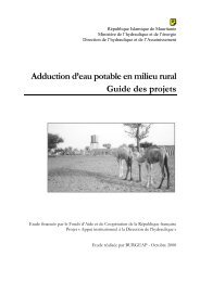
2.1.3 Types of geological formation<br />
Figure 1 shows a hypothetical geological situation in which<br />
different sources of groundwater may (or may not) be<br />
tapped by dug wells or boreholes (also called ‘tube wells’).<br />
A) Perched aquifers<br />
At site A, a shallow dug well may provide a little water from<br />
a ‘perched’ aquifer in the weathered zone above relatively<br />
impervious (low porosity) mudstones. If this well was<br />
extended into the mudstones it might produce very little<br />
additional water. A perched aquifer is normally limited in<br />
size and lies on an impervious layer higher than the area’s<br />
general water table.<br />
B) Shallow unconfined aquifers<br />
The term ‘unconfined’ refers to an aquifer within which the<br />
water is open to atmospheric pressure: the so-called<br />
Weathered zone<br />
A<br />
B<br />
C<br />
River flow<br />
D<br />
E<br />
Low porosity<br />
Massive granite<br />
Sandstone<br />
aquifer<br />
Solid<br />
claystones<br />
Fissured<br />
limestone<br />
Metamorphic basement<br />
Figure 1. A hypothetical hydrogeological scenario
20<br />
TECHNICAL REVIEW<br />
piezometric surface (pressure head level) is the same as the<br />
static water level (SWL) in the borehole. At site B, a borehole<br />
extracts water from an unconfined sandstone aquifer, the<br />
SWL of which is somewhat lower than the level of flow in<br />
the river. This sandstone aquifer is in a good catchment<br />
area because of recharge from the river.<br />
C) Confined aquifers<br />
A ‘confined’ aquifer may hold groundwater under greater<br />
pressure, so that when punctured by a borehole, the SWL<br />
rises to the higher piezometric level. If the piezometric<br />
surface happens to be above ground level (which is not<br />
uncommon), water will flow out of the borehole by itself:<br />
this is known as ‘artesian water.’ Deep borehole C intersects<br />
the sandstone aquifer and a deeper confined aquifer in<br />
fissured limestone; because of overpressure in the limestone<br />
aquifer, the SWL in C may be at the same or higher<br />
elevation than in B. The limestone aquifer may have no<br />
source of replenishment; so the water in it is ancient, or<br />
‘fossil,’ and could be exhausted if over-exploited.<br />
D) Fracture zone<br />
Borehole D, which has been drilled into fractured granite<br />
(shaded area), finds water held in the fracture zone. Fracture<br />
zones develop during geological times as a result of the<br />
severe mechanical stress, caused by tectonic movements,<br />
that is exerted on non-plastic formations.<br />
E) Hydrogeological basement<br />
Site E, a borehole sunk into massive granite on top of a hill,<br />
is dry. In this situation, it would be a waste of time and<br />
money to extend a deep borehole (such as C) into the<br />
metamorphic basement, which is generally known as the<br />
‘hydrogeological basement’ or ‘bedrock.’ The bedrock<br />
marks the level below which groundwater is not likely to<br />
be found.
2. GROUNDWATER AND THE ADVANTAGES OF BOREHOLES21<br />
2.2 Groundwater extraction<br />
A water borehole is not just a hole in the ground. It has to<br />
be properly designed, professionally constructed and carefully<br />
drilled. Boreholes for extracting water consist essentially<br />
of a vertically drilled hole (inclined and horizontal<br />
boreholes are rare and will not be discussed here), a strong<br />
lining to prevent collapse of the walls, which includes a<br />
means of allowing clean water to enter the borehole space<br />
(screen), surface protection, and a means of extracting<br />
water. Drilling by machine is an expensive process, and<br />
boreholes require professional expertise for both their<br />
design and their construction. There are, however, compensations:<br />
this method of extracting water has a number of<br />
significant advantages.<br />
The common alternatives to drilled boreholes, available to<br />
everyone with basic knowledge and simple tools, are surface<br />
water sources, springs, and dug wells. Where shallow<br />
groundwater emerges at a seepage site or at a spring, water<br />
catchment systems can be constructed to provide water of<br />
reasonable quality. Catchment boxes, that include sand or<br />
stone filters, and collector sumps are extremely effective<br />
means of collecting water. Gravity may be used to effect<br />
pipe network distribution from upland springs. Shallow<br />
dug wells usually exploit near-surface groundwater. Wells<br />
down to a depth of five metres are relatively simple to<br />
construct (given time and willing local labour), and there<br />
are many publications describing this process. Furthermore,<br />
because of their relatively large diameter, wells provide<br />
valuable storage volume. The water supply can be protected<br />
by lining the well, covering it with a lid, and fitting<br />
a hand-pump to it.<br />
However, dug wells, and surface water catchment in general,<br />
are very vulnerable to contamination caused by agricultural<br />
activities, animals, poor sanitation and refuse. In<br />
addition, surface or shallow groundwater catchment is<br />
vulnerable to poor rainfall and declines in water level<br />
caused by drought, because it usually taps the top of the
22<br />
TECHNICAL REVIEW<br />
aquifer. Borehole water, by contrast, often requires no treatment<br />
and is less susceptible to drops in water level during<br />
periods of drought or limited rainfall.<br />
2.2.1 Advantages of drilled boreholes<br />
If they are properly designed and maintained, drilled<br />
boreholes:<br />
• y Are less vulnerable to drought or drops in water level<br />
when drilled into deep water-bearing formations<br />
• y Can be designed to exploit more than one aquifer (when<br />
individual aquifers are vertically separated and not<br />
hydraulically connected)<br />
• y Are less vulnerable to collapse<br />
• y Are less vulnerable to contamination<br />
• y Are, if properly sited, capable of producing large yields;<br />
so, mechanically or electrically powered pumps can be<br />
used<br />
• y Are amenable to quantitative monitoring and testing,<br />
which enables accurate assessment of aquifer parameters<br />
(as in aquifer modelling), water supply efficiency,<br />
and optimal design of pump and storage/distribution<br />
systems<br />
• y Can be used to monitor groundwater levels for other<br />
purposes, e.g. environmental studies or waste disposal<br />
2.2.2 Disadvantages of drilled boreholes<br />
y • High initial material costs and input of specialized expertise,<br />
i.e. construction, operation, and maintenance<br />
may require skills and expensive heavy equipment<br />
y • Vulnerable to irreversible natural deterioration if inadequately<br />
monitored and maintained<br />
y • Vulnerable to sabotage, can be irreparably destroyed<br />
with little effort if inadequately protected<br />
y • Require a source of energy if water extraction pumps are<br />
used (unlike gravity feed systems)<br />
y • Do not allow direct access, for maintenance or repairs, to<br />
constructed parts that are underground
3. mETHods<br />
of dRILLING<br />
boreholes
24<br />
TECHNICAL REVIEW<br />
Once a suitable site has been selected and borehole drilling<br />
decided on, the proper drilling method must be chosen.<br />
Another primary consideration in project planning is the<br />
availability of existing water sources and water points.<br />
There may be completed dug wells and boreholes already<br />
in the area. Are they in use? If not, can they be rehabilitated<br />
to augment water availability or to reduce the cost of the<br />
programme? Drilling equipment, such as compressors, can<br />
be used to bring disused boreholes back into use; the question<br />
of rehabilitation will be addressed in Section 10 of this<br />
review. This section outlines the factors that must be considered<br />
when choosing a drilling method.<br />
3.1 Common drilling methods<br />
Essentially, a drilling machine consists of a mast from which<br />
the drilling string components (tools plus drill pipes or<br />
cable) are suspended and, in most cases, driven. Modern<br />
systems are powered rotary-driven, but it is probably worth<br />
a short digression to describe some methods of manual<br />
drilling for water. Simple, low-cost methods include:<br />
A) Hand-auger drilling<br />
Auger drills, which are rotated by hand, cut into the soil<br />
with blades and pass the cut material up a continuous<br />
screw or into a ‘bucket’ (bucket auger). Excavated material<br />
must be removed and the augering continued until the<br />
required depth has been reached. Auger drilling by hand<br />
is slow and limited to a depth of about 10 metres (maximum<br />
20 metres) in unconsolidated deposits (not coarser than<br />
sand), but it is a cheap and simple process.<br />
B) Jetting<br />
A method whereby water is pumped down a string of rods<br />
from which it emerges as a jet that cuts into the formation.<br />
Drilling may be aided by rotating the jet or by moving it up<br />
and down in the hole. Cuttings are washed out of the<br />
borehole by the circulating water. Again, jetting is useful
3. METHODS OF DRILLING BOREHOLES25<br />
only in unconsolidated formations and only down to relatively<br />
shallow depths, and would have to be halted if a<br />
boulder is encountered.<br />
C) Sludging<br />
This method, which may be described as reverse jetting,<br />
involves a pipe (bamboo has been successfully employed)<br />
being lowered into the hole and moved up and down,<br />
perhaps by a lever arm. A one-way valve (such as someone’s<br />
hand at the top of the pipe) provides pumping action as<br />
water is fed into the hole and returns (with debris) up the<br />
drill pipe. There may be simple metal teeth at the cutting<br />
end of the pipe, and a small reservoir is required at the top<br />
of the hole for recirculation. The limitations of sludging are<br />
similar to those of the previous two methods, but it has<br />
been used effectively in Bangladesh.<br />
These manual shallow drilling techniques might be used as<br />
low-cost alternatives in groundwater investigations for dug<br />
well sites, particularly if geophysical surveys prove to be<br />
ineffective, unavailable or impracticable because of ground<br />
conditions. In such instances, when the drilling is done<br />
solely for the purpose of prospecting, only small holes are<br />
drilled, rapidly.<br />
D) Percussion drilling<br />
Drilling by percussion is done by simply dropping a heavy<br />
cutting tool, of 50 kilograms or more, repeatedly in the<br />
hole. This may well be the original method of drilling for<br />
water, pioneered by the Chinese (probably using bamboo)<br />
3000 years ago or more. The drilling tools are normally<br />
suspended by a rope or cable; and – depending on the<br />
weight of the drill string, which, for manual operation, is<br />
obviously limited – it is possible to drill to considerable<br />
depths in both soft and hard formations. Basic percussion<br />
drilling systems are still widely used in Pakistan to drill<br />
shallow boreholes for hand-pumps. They consist of a strong<br />
steel tripod, cable and power winch, percussion tools, and<br />
a baler. These systems are seriously hindered when the
26<br />
TECHNICAL REVIEW<br />
ground is hard, and can accidentally change direction<br />
along weaker zones, causing boreholes to become crooked<br />
or tools to jam. Unconsolidated materials, although easy to<br />
drill with cable tool, become very obstructive when boulders<br />
are present. Sticky shales and clays are also difficult to<br />
penetrate with cable tool rigs, and loose sand tends to<br />
collapse into the hole almost as fast as it can be bailed.<br />
E) Rotary drilling and down-the-hole hammer (DTH)<br />
Most borehole applications in the field will require rotary<br />
drilling. True rotary drilling techniques allow much deeper<br />
boreholes to be constructed, and use circulating fluids to<br />
cool and lubricate the cutting tools and to remove debris<br />
from the hole. Circulating fluids usually take the form of<br />
compressed air or of pumped water with additives, such as<br />
commercial drilling muds or foams (see Section 5).<br />
The down-the-hole hammer is a further development of<br />
the rotary method.<br />
Table 2. Comparison of drilling methods<br />
Advantages<br />
Disadvantages<br />
Manual construction Simple technology using cheap labour Shallow depths only<br />
(Hand dug wells<br />
and hand drilling)<br />
Percussion drilling Simple rigs, low-cost operation Slow, shallow depths only<br />
Rotary drilling,<br />
direct circulation<br />
Rotary DTH,<br />
air circulation<br />
Rotary, reverse<br />
circulation<br />
(not described in text)<br />
Fast drilling, no depth limit, needs no<br />
temporary casing<br />
Very fast in hard formations, needs no<br />
water, no pollution of aquifer<br />
Leaves no mud cake, rapid drilling in<br />
coarse unconsolidated formations at<br />
large diameters<br />
Expensive operation, may need large<br />
working space for rig and mud pits,<br />
may require a lot of water, mud cake<br />
build-up may hamper development<br />
Generally not used in soft, unstable<br />
formations, drilling depth below water<br />
table limited by hydraulic pressure<br />
Large, expensive rigs, may require a<br />
lot of water
3. METHODS OF DRILLING BOREHOLES27<br />
Figure 2. A mud rotary machine working in eastern Zimbabwe, 1996. Note the mud pits dug nearby.<br />
Figure 3. Air rotary machine developing a successful borehole, South Africa, 1989
4. dRILLING<br />
equipmENT
30<br />
TECHNICAL REVIEW<br />
Once a drilling method has been selected, you must decide<br />
on the type of drilling equipment or rig that best suits your<br />
situation. This section discusses the various types of rig<br />
available and their suitability, and also provides an overview<br />
of drilling rig parts.<br />
Percussion rigs will<br />
not often be encountered<br />
these days in<br />
water borehole deep<br />
drilling; they are more<br />
useful in shallow site<br />
investigations or<br />
exploration. Some<br />
years ago, this writer<br />
saw an old cable tool<br />
percussion machine<br />
mounted on a large<br />
trailer, drilling<br />
exploration holes<br />
around an opencast<br />
manganese mine at<br />
Hotazel on the<br />
Western Cape in<br />
South Africa.<br />
4.1 Choosing a drilling rig<br />
The type of rig chosen may be determined on the basis of<br />
the site geology, the anticipated depths of the boreholes,<br />
and their expected diameters. Access is an important<br />
consideration. All drilling machines, except the smallest<br />
units capable of being dismantled and reassembled on<br />
site, require transportation: a road may have to be cut<br />
through bush to reach a location. For the largest truck or<br />
trailer-mounted rigs this can be a significant problem<br />
during rainy seasons in remote areas. Heavy rigs are notorious<br />
for becoming stuck in mud, and in such difficult<br />
conditions they should be used only if rain is not expected,<br />
or if there are means of pulling the rig out of trouble.<br />
Because low-lying areas often provide good drill sites, a<br />
rig may have to labour up a steep slope when it leaves.<br />
Rutted dirt roads may have to be covered with stones to<br />
facilitate traction.<br />
4.1.1 Percussion drilling<br />
Mechanical winching obviously improves the effectiveness<br />
of percussion drilling (light cable tool rigs), and a number<br />
of useful choices are available. One example is the Forager<br />
55 cable-trailer rig (Figure 4): weighing only 400 kilograms,<br />
it can be transported easily to inaccessible sites. The tripod<br />
frame can be erected by one person; and the heart of the<br />
system is a small free-fall winch, which hoists and drops<br />
the tool-set to drill the hole. Power can be provided either<br />
mechanically or hydraulically, although the supplier<br />
doesn’t recommend the latter for use overseas. However,<br />
this kind of rig is not adapted to hard formations or sediments<br />
containing blocks. In collapsible formations, the<br />
drilling depth is limited by the hauling capacity of the
4. DRILLING EQUIPMENT31<br />
equipment used to retrieve the temporary casing that<br />
maintains the walls of the hole. The unit and its accessories<br />
are available from the Consallen Group in the UK (Product<br />
reference 1, Annex 7).<br />
4.1.2 Heavy duty cable tool<br />
Heavy-duty cable tool percussion drilling rigs are truck or<br />
trailer-mounted and powered by a large diesel engine<br />
driving a cable winch. To add extra weight and drilling<br />
power, a ‘sinker’ – or heavy solid steel bar – is fitted above<br />
the chisel-like cutting tool. This usually improves borehole<br />
straightness and verticality. Percussion rigs allow operators<br />
to vary the number of strokes per minute and the length of<br />
each stroke, to optimize penetration in hard or soft rock<br />
conditions. By adding water, cuttings are removed from a<br />
percussion-drilled borehole in the form of a slurry and by<br />
means of a ‘bailer’ (heavy steel tube with a non-return<br />
‘clack’ valve at the bottom). Softer, unstable formations<br />
such as sands or clays may require a combined hollow cutting<br />
and bailing tool.<br />
4.1.3 Rotary drilling<br />
Industrial rotary rigs are truck or trailer-mounted, but small<br />
and extremely powerful machines (see below), often costeffective<br />
for humanitarian projects, are also on the market.<br />
One example is the Eureka Port-a-Rig, which can be transported<br />
by a pick-up truck in component form and assembled<br />
on site. The basic unit weighs about 500 kilograms and<br />
is driven by a 4-kw engine, with top drive and mud or air<br />
flush. A small 7-bar compressor, mounted on a small trailer,<br />
is available. The Eureka is capable of drilling to 50 metres<br />
(Product reference 2, Annex 7).<br />
The smallest rotary drilling system of which this writer has<br />
first-hand experience is the PAT 201. The system is powered<br />
by a small petrol engine in a mounting that can slide up and<br />
down a three-legged mast. It is recommended only for mud<br />
drilling in alluvial conditions, but this writer can confirm<br />
that the PAT 201 is indeed capable, as the manufacturers<br />
Figure 4. The Forager 55<br />
cable-trailer rig in use<br />
Operating a PAT 201<br />
in South Sudan for a<br />
Dutch NGO, this writer<br />
had to erect a gantry<br />
consisting of three<br />
telephone poles (two<br />
uprights and one<br />
cross-beam) from<br />
which a 5-tonne chain<br />
block was suspended.<br />
On one or two<br />
occasions, the chain<br />
block, pulling on the<br />
engine mounting, was<br />
able to free the drill<br />
pipes and drag bit,<br />
which had become<br />
jammed when the<br />
borehole collapsed.
32<br />
TECHNICAL REVIEW<br />
claim, of drilling to 60 metres. However, there is little power<br />
available for ‘pull back’ (just a small hand-winch), which is<br />
the main limitation of small rigs.<br />
Figure 5. A PAT 301 drilling rig<br />
The PAT Company (Product reference 3, Annex 7) produces<br />
a range of small to medium-sized drilling rigs: the 201, 301<br />
(shown in Figure 5), 401, and the 501, all of which use<br />
3-metre drill pipes. The PAT 301 and 401 operate hydraulically<br />
and may be towed or carried by a light pick-up, such<br />
as a Land Cruiser. Both can use water/mud or compressed<br />
air flushing and are capable of drilling to depths of 150 or<br />
200 metres at diameters of up to eight or nine inches. Mud<br />
pumps are available for PAT rigs, and compressors of up to<br />
7 to 12-bar capacity can be supplied for the larger rigs. In<br />
size and capability, the 501, a unit mounted on a 6½-tonne<br />
truck, falls between small portable machines and large<br />
industrial drilling rigs, which are generally custom-built.<br />
Needless to say, the<br />
dangers inherent in<br />
using high-pressure<br />
air systems require<br />
that pressure hoses<br />
and couplings be of<br />
the correct rating and<br />
in good condition.<br />
This is especially<br />
important when<br />
working in remote<br />
areas where access to<br />
emergency medical<br />
care may be many<br />
hours’ drive away.<br />
Circulation systems require a pump to drive the fluid: in the<br />
case of mud-rotary drilling, a mud pump, and for air systems,<br />
a compressor. Conveniently sized units are available<br />
for the smaller rigs: for example, PAT produces a small<br />
mechanical mud pump for the 201 portable rigs. Large rigs<br />
Figure 6. <strong>ICRC</strong> PAT 401 in action, northern Uganda, 2008
4. DRILLING EQUIPMENT33<br />
use industrial-scale units. Mud pumps are essentially simple<br />
sludge pumps based on pistons, impellors, or helical stators.<br />
For compressors, manufacturers specify the pressure<br />
a unit may develop in terms of ‘bar’ or ‘psi’ (pounds per<br />
square inch), where 1 bar = 100 kPa, (1 Pa = 1 N/m 2 ). Heavyduty<br />
(industrial plant) units can develop pressures of<br />
20 bar – and it is pressure that delivers power to a downthe-hole<br />
(DTH) hammer – making for a faster penetration<br />
rate. Pressure also lifts cuttings to the surface: for instance,<br />
a 7-bar compressor would be required to lift a 60-metre<br />
column of water from the bottom of a hole. Because the<br />
production of compressed air is a notoriously inefficient<br />
process, the compressor might dominate a drilling set-up<br />
in terms of size, cost, and maintenance problems.<br />
Many contractors<br />
construct their own<br />
machines using, for<br />
example, particular<br />
makes of truck chassis,<br />
engine or compressor,<br />
for which spare parts<br />
are readily available.<br />
The budgets of aid organizations seldom permit the purchase<br />
of industrial-sized drilling machines, but it is these<br />
that will normally be used if a drilling contractor is hired for<br />
a project. Large drilling rigs can be bought ‘off the shelf’ by<br />
commercial operators: the Atlas Copco machines and the<br />
Dando company, which manufactures the extremely successful<br />
Watertec 24 rig shown in Figure 7, will be familiar<br />
names to many drillers and hydrogeologists. The W24, a<br />
typical example of this type of machine, has a ‘pull back’ of<br />
24,000 kilograms and can drill to depths greater than<br />
700 metres with bit diameters of up to 17½ inches. It was<br />
developed specifically to cope with the harsh conditions<br />
encountered in Africa and in Arab countries. The W24 is one<br />
of many rigs that can be adapted for air or mud circulation<br />
as required.<br />
Figure 7. The Dando Watertec<br />
24 drilling rig
34<br />
TECHNICAL REVIEW<br />
4.2 Drilling rig components<br />
Figure 8. Two common types<br />
of drill bit: left, two drag bits;<br />
right, a roller cone bit.<br />
Anyone familiar with<br />
drilling contractors’<br />
operations in the field<br />
will know the extent to<br />
which downtime can<br />
adversely affect the<br />
schedule of a project.<br />
Problems commonly<br />
arise in hydraulic<br />
systems and compressors<br />
that might have<br />
been inadequately<br />
maintained because of<br />
the pressure of work.<br />
4.2.1 Drill bit<br />
No single type of drill bit can cope with all possible drilling<br />
conditions and formations. Some typical examples are<br />
shown in Figure 8. Drag bits consist of three or four serrated<br />
blades that shear the formation when the bit is rotated; they<br />
can penetrate softer formations such as poorly consolidated<br />
or stiff clays and mudstones rapidly. Roller cone bits (or<br />
tricone rock bits), which can be used with air or liquid<br />
flushing, are popular with the oil industry. They can be used<br />
to penetrate both soft and relatively hard formations.<br />
4.2.2 Hammer<br />
In air-circulation drilling, if a formation is too hard for penetration<br />
by a drag bit, a DTH hammer is generally employed.<br />
This tool was developed for the mining and quarrying<br />
industry. The ‘business’ end – the button bit – is studded<br />
with hemispherical tungsten carbide ‘buttons,’ and with<br />
channels built in to allow the passage of compressed air.<br />
When the hammer is pressed against the ground, the bit is<br />
forced into a pneumatic hammer action (like a road drill) by<br />
compressed air fed down the drill pipes. Then, as the tool<br />
is rotated in the hole, the buttons act across the entire base<br />
of the borehole. Most hammers rotate at speeds of 20 to 30<br />
revolutions per minute, and blows can be struck at rates of<br />
up to 4000 per minute. Debris is normally flushed (blown)<br />
Figure 9. DTH hammer button bits. The hammer body, into which<br />
it slides, is not shown.
4. DRILLING EQUIPMENT35<br />
out of the hole at the end of each drill pipe. DTH hammers<br />
are most effective in hard rock formations such as limestones<br />
or basalts; soft, fine-grained formations tend to clog<br />
the air ducts or jam the piston slides.<br />
Nonetheless, DTH hammers are extremely cost-effective<br />
and hence very popular with commercial drillers.<br />
In remote locations,<br />
and when the<br />
pressure of work is<br />
heavy, hammer<br />
maintenance can<br />
easily be overlooked,<br />
to the detriment of a<br />
project’s schedule.
5. borehole<br />
consTRuCTIon
38<br />
TECHNICAL REVIEW<br />
Once the drilling method and the equipment have been<br />
chosen, you will be required to observe and monitor the<br />
construction of the borehole. You may also be charged<br />
with the responsibility of supervising (in terms of quality<br />
control) the drilling of boreholes by your colleagues or by<br />
external drilling contractors. Quality control of drilling<br />
operations requires knowledge and confidence, which are<br />
acquired only by experience; but a cooperative contractor<br />
(sympathy would be too much to expect!) can make a job<br />
easier, and even enjoyable. This section outlines key considerations<br />
for borehole construction using the mud and<br />
air rotary drilling methods.<br />
5.1 Construction considerations<br />
Large drilling rigs are equipped to ensure that a borehole is<br />
started true and vertical. Maintaining verticality and<br />
straightness can be difficult during the early stages of<br />
drilling, but as the drill string weight increases, this problem<br />
tends to dissipate unless highly heterogeneous drilling<br />
conditions are encountered (in the form of boulders or cavities).<br />
Straightness is particularly important for water boreholes<br />
in which long strings of casing and screens may have<br />
to be installed with a gravel pack filter (see Section 6.3.2).<br />
Non-vertical or inclined drilling is used mostly in oil and<br />
mineral extraction. Tools used for water boreholes are not<br />
suited to inclined drilling.<br />
As drilling proceeds, drill pipes are screwed together. It<br />
should be noted that two of the three bits shown in Figure 8<br />
have conical screw threads. This allows tools and pipes to<br />
be rapidly attached and screwed together on the rig.<br />
A blast of air is sent through each pipe to remove blockages,<br />
and the string is tightened with heavy-duty spanners<br />
on the rig. Taller drill masts can obviously handle longer<br />
drill pipes – six metres is the normal length, except for<br />
smaller rigs (see above) – which speeds up bit lowering<br />
(‘tripping-in’) and raising (‘tripping-out’) times.
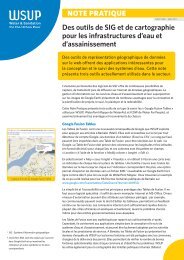
5. BOREHOLE CONSTRUCTION39<br />
Ground<br />
level<br />
First hole drilled<br />
with 12" bit for<br />
conductor pipe<br />
Drill table<br />
Drill jacking leg<br />
Temporary plug<br />
Cuttings pile<br />
Temporary plug<br />
10" steel conductor pipe<br />
in very unstable superficial<br />
material<br />
Second stage<br />
drilled with 8" bit<br />
down to stable<br />
formation<br />
7" temporary steel casing<br />
inserted down to top<br />
of stable formation<br />
Third stage<br />
drilled with 6" bit<br />
down to borehole<br />
final depth in stable<br />
formation<br />
Drill pipe<br />
Drill bit<br />
Figure 10. Schematic section of an example of temporary borehole<br />
completion (not to scale).<br />
Reaming – the enlarging of an existing hole – can be carried<br />
out either with a drill bit of any kind or with specially<br />
designed reaming tools. Drilling companies often devise<br />
tools for special use, sometimes in the field, and they are<br />
often very ingenious.<br />
It should be borne in mind that after drilling has begun,<br />
the sides of the upper part of the borehole are likely to<br />
suffer erosion by circulation fluid and cuttings, which<br />
causes an irregular enlargement of the borehole, reducing<br />
up-hole fluid (air or mud) velocity. This can be dealt with by<br />
installing conductor pipe as described below.<br />
As drilling proceeds, the amount of water leaving the<br />
borehole will – it is hoped – be seen to increase, reaching<br />
Objects lost in the<br />
hole can often be<br />
‘fished’ out using<br />
existing equipment<br />
(such as pipe screw<br />
threads) or with<br />
specially adapted<br />
tools. But drillers<br />
should always take<br />
great care to prevent<br />
this kind of occurrence,<br />
as minor<br />
accidents are<br />
potentially very costly<br />
in terms of time and<br />
equipment.
40<br />
TECHNICAL REVIEW<br />
a point at which it becomes clear that the borehole will<br />
provide the required supply. Even then, the borehole may<br />
have to be deepened further to provide sufficient pumping<br />
drawdown (see Section 6.3.2). However, if the borehole is<br />
found to be wanting, it may be advisable to stop drilling<br />
early (unless a hand-pump is acceptable at that location) or<br />
carry on in the hope of a greater water strike (here some<br />
knowledge of local geology would be very useful). If fragments<br />
of ancient, hard metamorphic or igneous basement<br />
rocks, such as gneisses, schists, and granites start appearing<br />
in the cuttings, and the penetration rate decreases significantly,<br />
the ‘hydrogeological basement’ has, in all likelihood,<br />
been reached and it would probably be futile to continue<br />
to deepen the hole.<br />
If a manufactured dip<br />
meter cannot be<br />
obtained, one can be<br />
fashioned simply, with<br />
about 100 metres of<br />
ordinary twin-core<br />
domestic lighting flex<br />
and a cheap electrical<br />
test meter (with a<br />
resistance – Ω – scale).<br />
Connect one end of<br />
the cable to the meter<br />
and lower the free end<br />
with bared wires,<br />
which may be<br />
weighted with a piece<br />
of metal, into the<br />
borehole. When the<br />
bare wires touch the<br />
water, the meter will<br />
register a current.<br />
When that happens,<br />
mark the cable, pull it<br />
out, and measure the<br />
length from the bared<br />
end to the mark.<br />
Penetration rate through each zone or formation in the<br />
borehole may be determined simply by timing the progress<br />
of one drill pipe or a fixed distance marked by two chalk<br />
marks on the drill pipes as they pass through the table.<br />
Penetration rate can provide an estimate of formation<br />
consolidation or hardness, and also show precisely when<br />
an aquifer was crossed.<br />
The question, then, is: When to stop drilling? The supervisor<br />
normally has an idea, from the project specifications, of<br />
how much water is required from a borehole; a hand-pump,<br />
for instance, does not demand a large supply (0.5 litre/sec<br />
is more than enough), whereas a motor pump supplying a<br />
storage tank for a village, a refugee camp, or a facility such<br />
as a school requires a significantly greater yield.<br />
When drilling is finally stopped by the supervisor (who<br />
normally bears this responsibility), it is advisable to allow a<br />
few minutes for the water level in the borehole to recover<br />
and to then measure it with a cable dip meter.<br />
Field hydrogeologists and water engineers working on<br />
borehole drilling projects in the commercial or humanitarian<br />
sectors are most likely to encounter rotary drilling
5. BOREHOLE CONSTRUCTION41<br />
machines (of whatever size) using mud circulation or<br />
compressed air. For this reason, the discussion in this review<br />
is limited to those techniques most commonly used in<br />
water borehole drilling: mud rotary and air rotary, as cablepercussion<br />
drilling, auger drilling, and other methods are<br />
becoming increasingly rare.<br />
5.1.1 Mud rotary drilling<br />
Besides the cooling and lubrication of drilling bits, which<br />
has already been mentioned, the addition of special muds<br />
or other additives to circulating water provides the<br />
following significant advantages when drilling in unstable<br />
formations:<br />
• y By using fluids of a density higher than that of water<br />
itself, significant hydrostatic pressure is applied to the<br />
walls of the borehole, preventing the formation from<br />
caving in<br />
• y The liquid forms a supportive ‘mud cake’ on the wall of<br />
the borehole, discouraging the collapse of the<br />
formation<br />
• y The liquid holds cuttings in suspension when drilling is<br />
halted for the addition of drill pipes<br />
• y The liquid removes cuttings from the drill bit, carries<br />
them to the surface, and deposits them in mud pits (see<br />
below)<br />
Drilling mud – a partially colloidal suspension of ultra-fine<br />
particles in water – fulfils these functions by virtue of its<br />
properties of velocity, density, viscosity, and thixotropy<br />
(ability to gel or freeze when not circulated). Water by itself<br />
exerts hydrostatic pressure at depth in a borehole, but at<br />
shallow depths this may not be sufficient. Among additives<br />
for increasing the density of water, salt is one of the most<br />
convenient; but one of the most widely used is a natural<br />
clay mineral known as bentonite (calcium montmorillonite),<br />
which swells enormously in water. A slurry consisting<br />
of water and bentonite combined in the proper<br />
proportions has a higher viscosity than water and forms a<br />
mud cake lining in the borehole. However, a major
42<br />
TECHNICAL REVIEW<br />
disadvantage is that the mud needs to be mixed and left<br />
for some 12 hours before use to allow the viscosity to<br />
build up.<br />
The normal bentonite mud mix is 50 kilograms per cubic<br />
metre of water (a 5% mix), or 70 kilograms per cubic<br />
metre, if caving formations are expected.<br />
However, this writer<br />
found that, at daily<br />
temperatures of<br />
between 38 and<br />
42 degrees Celsius or<br />
more in Sudan, guar<br />
gum mud (a particular<br />
brand purchased in<br />
Nairobi) did not last<br />
more than a day:<br />
decomposition and<br />
loss of viscosity<br />
began the next day.<br />
Natural polymers provide a more practical solution for<br />
water boreholes, but they are relatively expensive, so<br />
should be used with care. One example of such a polymer,<br />
used in oilfield and water drilling, is guar gum, an off-white<br />
coloured powder extracted from guar beans. It is an<br />
effective emulsifier used in the food industry, so is biodegradable,<br />
and will lose its viscosity naturally after a few<br />
days. Polymers are best mixed by sprinkling the powder<br />
into a jet of water, to prevent the formation of lumps. The<br />
polymer mud should be mixed during the setting-up<br />
stage – a minimum of 30 minutes is usually required – so<br />
that it has time to ‘yield’ (build up viscosity).<br />
The normal mix for guar gum polymer is one kilogram<br />
per cubic metre of water; for drilling in clay formations,<br />
use up to 0.5 kilogram per cubic metre, and for caving<br />
formations, use one to two kilograms per cubic metre.<br />
Besides the usual mud properties, polymer drill fluids also<br />
coat clay cuttings, preventing the formation of sticky<br />
aggregates above a drill bit (known as ‘collars’), which can<br />
hold up drilling while they are removed (a simple remedy<br />
for clay aggregation is to add salt to the drilling fluid).<br />
Another advantage of polymers is that they make it possible,<br />
when it is clay that is being drilled through, to distinguish<br />
genuine formation samples from the mud.<br />
Degradation of polymer muds is accelerated by high<br />
ambient temperatures, acidity, and the presence of bacteria<br />
(using the polymer as a food source): polymer-based mud<br />
might last only two or three days in tropical conditions, and<br />
can cause bacterial infection of the borehole.
5. BOREHOLE CONSTRUCTION43<br />
It could be that natural polymer powders have a limited shelf<br />
life, and this should be checked before purchasing stock from<br />
a supplier. Food-grade bacterial inhibitors have been used<br />
as additives to prevent the breakdown of polymer-based<br />
muds. When using polymers, observe the manufacturer’s<br />
guidelines. Foaming agents are also widely used as drilling<br />
fluid additives, normally in air drilling (see Section 5.1.2).<br />
A) Checking the viscosity of drilling mud<br />
Every mud additive (bentonite, mud, salt, etc.) must be<br />
mixed into the circulating water to provide the correct viscosity.<br />
This can be done initially in a specially prepared pit<br />
(see Figure 12), but as drilling proceeds, and especially if<br />
groundwater is struck, the mud will become diluted, and<br />
more mud or additive powder will have to be added. Too<br />
low a viscosity may result in fluid seeping into the formation,<br />
and it may later be difficult to remove the fine mud<br />
particles from the wall of an intersected aquifer, reducing<br />
the efficiency of the borehole (see Section 6.2). ‘Thin’ mud<br />
may also cause cuttings to fall back onto the drill bit, causing<br />
it to stick in the hole. The viscosity of drilling mud can be<br />
easily and frequently checked by means of a simple viscometer<br />
known as a Marsh funnel. This is a rugged plastic funnel,<br />
with a built-in screen or strainer to filter out lumps as the<br />
mud sample is poured in (shown in Figure 11; for details<br />
regarding its purchase, see Product reference 4, Annex 7).<br />
Marsh funnel viscosity is reported as the time in seconds<br />
required for one full quart (946 millilitres) of drilling mud to<br />
flow out of the funnel. The funnel is filled through the<br />
screen with a fresh mud sample up to a quart mark, or to<br />
the level of the built-in screen, while blocking the outlet<br />
with one finger. Allow the mud to run down into a quartgraduated<br />
or marked container and time the flow for one<br />
quart of mud. Remember also to note the ambient or mud<br />
temperature at the time of the measurement.<br />
Extremely porous or fissured formations can cause a loss of<br />
drilling fluid (mud); it is possible that the entire mud<br />
Figure 11. The Marsh funnel<br />
viscometer. Top, built-in funnel<br />
screen. Bottom, 1000 ml<br />
plastic measuring jug with<br />
one-quart (946ml) mark.
44<br />
TECHNICAL REVIEW<br />
Typical Marsh funnel times required for common drilling conditions<br />
Normal drilling mud<br />
35 to 45 seconds<br />
Medium sand<br />
45 to 55 seconds<br />
Coarse, permeable sands<br />
55 to 65 seconds<br />
Gravels<br />
65 to 75 seconds<br />
Coarse gravels<br />
75 to 85 seconds<br />
Zones of high permeability<br />
60 to 80 seconds<br />
Partial loss in water-bearing zones<br />
100+ seconds<br />
Caving sand may also need a high viscosity mud.<br />
Note : One quart of clean water normally runs out of a Marsh funnel in 25.5 seconds, one litre in 27 seconds.<br />
circulation might disappear into a cavity. This could put a<br />
stop to drilling altogether, if increasing fluid viscosity by<br />
adding more additive has no effect. If the area from which<br />
fluid is being lost is not likely to be part of an aquifer, fibrous<br />
materials such as sawdust, dried grass, or cow-dung could<br />
be introduced into the mud, while ensuring that a pumpable<br />
circulation is maintained. Such additives can block<br />
large pores and cavities permanently, which is why they<br />
should not be used to cure losses in a water-bearing zone.<br />
An alternative method is to add foaming agents, essentially soaps or detergents and<br />
biodegradable surfactants. Household detergents such as washing-up liquids and<br />
cold-water laundry soap powders are quite effective, if professional drilling additives<br />
are not available. A combination of drill mud and foaming agent can produce a<br />
mixture whose consistency resembles that of men’s shaving cream; this is extremely<br />
effective at blocking cavities and lifting material out of a borehole, especially if air<br />
can be introduced, even with a small compressor. A mix of about 5% foaming agent<br />
and 1% polymer mud produces a fairly viscous foam.<br />
Note: A stiff foam takes up more space and its use might<br />
necessitate larger settlement pits than originally<br />
envisaged.<br />
B) Mud pits<br />
To mix the mud, as described previously, mud pits are<br />
required. This can be combined with a ‘suction pit’ or sump<br />
from which a mud pump will take the circulation supply.
5. BOREHOLE CONSTRUCTION45<br />
Second, a larger, ‘settling’ pit is essential, in which mud<br />
returning to the surface from the borehole’s annular space<br />
will be allowed to drop its load of drill cuttings. The two pits<br />
and the borehole are usually connected by shallow channels<br />
or ditches and a weir; a typical arrangement is shown<br />
schematically in Figure 12. Mud pits are most commonly<br />
dug in the ground alongside the rig, but some contractors<br />
can supply steel tanks, which are their equivalent. If dug in<br />
soft soil, pits may be lined with plastic sheeting, clay or<br />
cement. Mud circulation through pits must be slow and<br />
steady, to settle the cuttings and to make collecting formation<br />
samples (normally taken from a channel close by the<br />
borehole) easier. The mud pump inlet and strainer are held<br />
by rope above the bottom of the suction pit, so that mud<br />
that is as clean as possible can be recirculated into the<br />
borehole via the drill pipes. Optional extra ‘swirl pits’ may<br />
be included between the borehole and the settling pit to<br />
Borehole/Rig<br />
Water/Mud mix<br />
Shallow<br />
channel<br />
Mud<br />
pump<br />
Suction pit/<br />
Sump<br />
Shallow channel or weir<br />
Settling pit<br />
Figure 12. Schematic plan view showing mud pits and mud<br />
circulation (anti-clockwise white arrows). Not drawn to scale.
46<br />
TECHNICAL REVIEW<br />
further aid settlement of debris. The capacity of the suction<br />
pit should be roughly equal to the volume of the hole being<br />
drilled; the capacity of the settlement pit should be at least<br />
three times that.<br />
To roughly calculate pit volumes,<br />
given hole diameter D in inches (drill bit size):<br />
Borehole volume and suction pit volume =<br />
D 2 H/2000 in cubic metres (or D 2 H/2 in litres),<br />
where H is depth of hole in metres.<br />
Settlement pit volume should be<br />
~0.002D 2 H cubic metres (or 2D 2 H litres).<br />
If borehole diameter changes, adjust calculations<br />
accordingly.<br />
The suction pit should be constructed as an approximately<br />
equal-sided cubic space; the settling pit should be approximately<br />
two to three times as long as it is wide and deep<br />
(e.g.. 2 × 1.5 × 1 or 3 × 1 × 1 m).<br />
The greyscale gradations show progressive settlement of<br />
drill cuttings up from the borehole annular space (dark<br />
ring) through the system, from dark grey (loaded mud) to<br />
pale grey (clean mud). The mud pump and mud hoses back<br />
to the drill pipe are shown in red. The yellow marker shows<br />
the area from which borehole cuttings samples should be<br />
obtained. The water/mud mix inlet is shown in blue.<br />
C) Return fluid velocities<br />
For mud rotary drilling, up-hole (return) fluid velocities<br />
should be within the range 15 to 30 metres/minute.<br />
The minimum capacity for a circulation pump can be calculated<br />
from the formula Q = 7.5 (D2 – d2) where Q is uphole<br />
flow rate in litres/minute for any combination of drill<br />
bit diameter D and drill pipe diameter d (both expressed in<br />
inches).
5. BOREHOLE CONSTRUCTION47<br />
Table 3. Mud rotary: Circulation fluid flow rates for a range of drill bit and drill pipe sizes<br />
Borehole<br />
(drill bit)<br />
diameter<br />
Drill pipe diameter<br />
58 mm (2 ¼") 75 mm (3") 88 mm (3 ½")<br />
Fluid flow litres/min Fluid flow litres/min Fluid flow litres/min<br />
Min Max Min Max Min Max<br />
75 mm 3" 30 60 — — — —<br />
90 mm 3 ½" 54 108 25 50 — —<br />
100 mm 4" 82 164 55 110 25 50<br />
125 mm 5" 150 300 120 240 100 200<br />
140 mm 5 ½" 180 380 160 320 135 270<br />
150 mm 6" 230 460 200 400 175 350<br />
200 mm 8" 450 900 415 830 390 780<br />
250 mm 10" 700 1400 685 1370 650 1300<br />
Table 3 shows the maximum and minimum fluid flow rates<br />
in litres/minute for various borehole (drill bit) diameters;<br />
maximum flow rates are about double the minimum.<br />
On successful completion of a borehole, mud cake, foam<br />
or other additives (if used), and all drilling debris must be<br />
washed out from the borehole. This is the development<br />
stage and is covered in Section 6.2. Suffice to say here that<br />
drilling muds often require other additives to effect their<br />
dispersal.<br />
5.1.2 Compressed air rotary drilling<br />
Using compressed air as the circulation medium does away<br />
with having to prepare and inject liquids into a borehole<br />
(although water and additives may be introduced for special<br />
purposes). In some cases, the use of air drilling may be<br />
essential: for example, when constructing observation<br />
holes for pollution studies, where groundwater contamination<br />
should be kept to a minimum. Even then, a formation<br />
may become contaminated by oil particles from the compressor.<br />
The principal features of air drilling may be summarized<br />
as follows:
48<br />
TECHNICAL REVIEW<br />
The use of a low-density circulation medium (air) requires<br />
high fluid velocities to lift debris out of the borehole. Thus,<br />
for large-diameter boreholes, large-capacity compressors<br />
are required (see Table 4).<br />
Dry formations present few obstacles for air drilling, but a<br />
water strike at depth requires that the air pressure overcome<br />
hydrostatic pressure to a significant degree, to<br />
operate the DTH hammer and carry water and cuttings to<br />
the surface. Damp formations can, however, cause problems,<br />
such as the accumulation of sticky cuttings above the<br />
drill bit (like the clay ‘collar’ referred to earlier).<br />
Air provides very little protection from borehole collapse,<br />
other than dry or damp pulverized rock powder that smears<br />
the wall of the borehole. Because softer formations are<br />
easily eroded, it is vital to protect the looser upper section<br />
of the borehole by inserting a suitable length of steel<br />
tubing known as a ‘conductor pipe,’ which is a little larger<br />
in diameter than the drill bit used when ‘spudding in’ (the<br />
very moment drilling starts at surface level). The conductor<br />
pipe should protrude a little above ground level – but not<br />
so much that it interferes with the rig drilling table – leaving<br />
space for cuttings to blow clear. Boreholes are drilled with<br />
larger bits at first, reducing diameter at depth, after<br />
installing temporary steel casing (protective lining inserted<br />
inside the conductor pipe) to protect areas of unstable<br />
Table 4. Air drilling: Maximum drill bit sizes for a range of compressor capacities and drill pipe sizes<br />
Compressor capacity<br />
m 3 /<br />
min<br />
litres/<br />
sec<br />
ft 3 /<br />
min<br />
Maximum borehole (drill bit) diameter<br />
Drill pipe diameter<br />
58 mm (2 ¼")<br />
Drill pipe diameter<br />
75 mm (3")<br />
Drill pipe diameter<br />
88 mm (3 ½")<br />
3 50 100 85 mm 3" — — — —<br />
5 80 175 100 mm 4" 115 mm 4 ½" 125 mm 5"<br />
7 120 250 115 mm 4 ½" 125 mm 5" 140 mm 5 ½"<br />
10 175 375 125 mm 5" 140 mm 5 ½" 150 mm 6"<br />
13 210 450 140 mm 5 ½" 150 mm 6" 165 mm 6 ½"<br />
17 280 600 150 mm 6" 165 mm 6 ½" 175 mm 7"
5. BOREHOLE CONSTRUCTION49<br />
formation. Typically, the drilling of a borehole by the air<br />
rotary method may consist of three stages of varying<br />
diameter, as shown in Figure 10.<br />
While air drilling, up-hole airflow rates should be within the<br />
range 900 to 1200 cubic metres/minute.<br />
The required compressor capacity can be calculated from<br />
the formula Q = ½ (D 2 – d 2 ) in cubic metres/minute (with<br />
D and d again being expressed in inches).<br />
Temporary casing may be particularly difficult to insert<br />
through a horizon containing stones or boulders (such as<br />
coarse river channel deposits), but unfortunately such<br />
formations often host good aquifers. DTH hammers can<br />
break hard rock boulders (or partially fragment them), but<br />
there is always the risk of the hammer diverting and<br />
becoming wedged, or lumps of rock falling behind the bit<br />
and jamming it in the hole. The best way to deal with<br />
boulders is to install a simultaneous casing system, which<br />
is supplied by most DTH hammer manufacturers. This<br />
allows steel casing to be pushed or pulled down a borehole,<br />
directly behind the hammer, to prevent the walls from<br />
caving in. The hammer has a large diameter bit that is used<br />
to make the hole for the casing; the bit can be mechanically<br />
reduced in size and retrieved through the casing. Such<br />
systems require rigs with strong masts and the power to<br />
handle heavy casing insertion in difficult drilling<br />
conditions.<br />
During air drilling, foams can be added through the drill<br />
pipes to eliminate dust emerging from a dry hole, to keep<br />
the borehole clean, and to prevent fine particles from clogging<br />
any small water-bearing fissures that may be intersected.<br />
Furthermore, soap bubbles help lift debris out of<br />
the borehole. However, foams do not provide any hydrostatic<br />
support for collapsing boreholes; they also make it<br />
difficult to collect samples at any drill depth.<br />
Cuttings samples<br />
during air drilling are<br />
usually obtained by<br />
pushing a shovel<br />
under the drill table<br />
alongside the<br />
conductor pipe. As<br />
the samples are blown<br />
out, rock fragments<br />
collect around the<br />
conductor pipe and<br />
some land on the<br />
shovel. At the<br />
prescribed sampling<br />
interval, the shovel is<br />
withdrawn with the<br />
fresh sample. Drillers<br />
often need to be<br />
reminded to collect<br />
these samples.
50<br />
TECHNICAL REVIEW<br />
However, drillers often<br />
forget to make these<br />
chalk marks. The<br />
supervisor must keep<br />
count of the number<br />
of drill pipes going<br />
into the hole. The total<br />
length of these, plus<br />
the length of the drill<br />
bit, is the correct<br />
depth (beware of drill<br />
pipes of slightly<br />
differing lengths).<br />
5.2 Borehole logging<br />
For a borehole to be properly logged, the driller and supervisor<br />
need to know its exact depth at all times. This is necessary<br />
for the calculation of drilling charges, and while<br />
designing the borehole (see Section 6). First, make a note<br />
of the length of the drill bit and of any other tools that may<br />
be used to drill the hole. Put the bit on the ground and<br />
make a chalk mark, ‘0,’ on the first drill pipe against a suitable<br />
fixed point on the rig and at a known height above<br />
ground level, such as the drilling table (which centralizes<br />
the drill pipes in the hole). From then on, marks can be<br />
made on the drill pipe at regular intervals – say, every half<br />
metre – to record the depth of drilling and to assist in the<br />
logging of penetration rates.<br />
A) Formation samples<br />
Formation samples need to be obtained as drilling proceeds:<br />
the usual sampling interval is one metre. These are obviously<br />
highly disturbed samples, having been sheared or broken<br />
from their parent formation, so should not be used to infer<br />
characteristics such as bedding, texture, porosity, or permeability.<br />
There will be a slight delay as formation fragments<br />
are lifted to the surface by the circulating mud, but a rough<br />
estimate of the up-hole velocity should enable one to calculate<br />
the actual depth at which cuttings were derived. Keep<br />
in mind that if mud viscosity is too high, or if formation<br />
collapse occurs (viscosity too low), some fragments could<br />
return to the borehole, with the potential of causing confusion.<br />
Cuttings obtained from the shallow mud channel near<br />
the borehole (see Figure 12) should be washed in water to<br />
remove mud, and laid out in order (by the depth at which<br />
each was acquired) on the ground or in a sample box with<br />
separate compartments for each sample. They can then be<br />
logged by the supervisor or site geologist and bagged if<br />
required. Samples should, of course, be labelled correctly<br />
with all information relevant to the job in hand.<br />
The main attributes of a borehole log are accuracy and<br />
consistency; a good set of logs can be a useful resource
5. BOREHOLE CONSTRUCTION51<br />
when planning future drilling programmes. Drillers must<br />
keep their own logs and notes and, as is often stipulated in<br />
contracts (see Section 11), these should be accurate; however,<br />
in practice, they cannot always be relied upon, especially<br />
if the supervisor is absent from the site for a period.<br />
All geological samples and water strikes should be logged<br />
by the drillers and the supervisor, as this important information<br />
will be required for designing the borehole and the<br />
equipment to be installed.<br />
Full borehole logging may also include geophysical logging,<br />
which is normally carried out only after a well has<br />
been completed. These systems are briefly described in<br />
Section 6.3.3.<br />
Water strikes made<br />
during mud rotary<br />
drilling are usually<br />
indicated (unless they<br />
are very minor) by a<br />
rapid dilution of the<br />
mud mix. Intersection<br />
of an aquifer during<br />
air drilling is much<br />
more obvious, as the<br />
machine will begin<br />
blowing out damp<br />
fragments of rock<br />
instead of dry dust.<br />
Annex 1 gives a typical example of a drilling log sheet,<br />
which is applicable for both mud and air drilling, and which<br />
should be kept by the supervisor. The driller’s log should<br />
also include information on drilling or other work time,<br />
standing (waiting) time, and downtime (breakdowns).
6. borehole desIGN,<br />
dEVELopmENT,<br />
ANd compLETIon
54<br />
TECHNICAL REVIEW<br />
Having drilled a borehole to the required depth, the supervisor<br />
should be armed with the following information:<br />
• y The depth of the borehole<br />
• y A lithological log of the borehole<br />
• y Borehole diameter(s) and depths of any diameter reduction<br />
• y Depths of water strikes (if any)<br />
• y Penetration rate log<br />
• y Approximate static water level in the borehole (or some<br />
indication of what this might be)<br />
All this data should appear on the borehole log sheet (see<br />
Annex 1), and should be used while designing the borehole.<br />
Some idea of the final design should already be in the mind<br />
of the supervisor when he or she is selecting drilling diameters.<br />
For example, if the borehole is required for a handpump,<br />
a large-diameter hole would be unnecessarily<br />
expensive; and only one size of bit – possibly two at most,<br />
because hand-pumps make lifting from great depths very<br />
hard work – will be needed.<br />
Once all the lengths of<br />
temporary casing and<br />
conductor pipe<br />
installed during drilling<br />
have been removed by<br />
the drillers, the depth<br />
of the borehole should<br />
be checked by a<br />
weighted plumb-line,<br />
in order that an<br />
accurate construction<br />
design may be<br />
drawn up.<br />
6.1 Borehole construction design<br />
As water is pumped out of a borehole, the water level in<br />
the hole falls. It may fall by an amount known as the<br />
‘pumping drawdown,’ which eventually stabilizes for that<br />
rate of extraction. If the water level does not stabilize and<br />
continues to drop until the borehole is ‘dewatered,’ the<br />
hole is being over-exploited. In this discussion it is assumed<br />
that boreholes are designed with the intention of maximizing<br />
yield and efficiency, the normal requirements for<br />
everything other than hand-pump-equipped holes.<br />
• y The maximum yield of a borehole is defined as that yield<br />
which the borehole can sustain indefinitely before drawdown<br />
exceeds recharge from the aquifer.<br />
• y Borehole efficiency is technically defined as the actual<br />
specific capacity (yield per unit of drawdown: say, litres<br />
per second per metre) divided by the theoretical specific<br />
capacity, both of which can be derived from a pumping<br />
test. Specific capacity declines as discharge increases.
6. BOREHOLE DESIGN, DEVELOPMENT, AND COMPLETION55<br />
6.1.1 Borehole casing<br />
Boreholes are constructed by inserting lengths of protective<br />
permanent casing. These are lowered or pushed into<br />
the hole by the drilling rig to the required depth; the<br />
lengths of casing may be joined together by means of<br />
screw threads, flange-and-spigot, gluing, riveting, or<br />
welding. Casing normally extends up to the surface, with a<br />
certain amount (say 0.7 metre) standing above ground<br />
level. Lengths of casing may be obtained in mild steel,<br />
stainless steel, and plastic (such as uPVC, ABS, polypropylene,<br />
and glass-reinforced plastics). Plastic casings are<br />
more fragile and deformable than steel casings (especially<br />
the screw threads), and so should be used mainly for lowyield<br />
and shallow boreholes. The casing should be capable<br />
of withstanding the maximum hydraulic load to which it is<br />
likely to be subjected, that is, about 10 kilopascals (kPa) for<br />
each metre that extends below the water level down to the<br />
maximum expected drawdown. Table 5 gives a few typical<br />
values of casing collapse strength (Clark, 1988), but because<br />
of the number of variables, it is advisable to consult manufacturers’<br />
specifications.<br />
Because of their<br />
fragility, plastic<br />
casings should be<br />
stored and shipped<br />
with care. Stack the<br />
materials properly in<br />
shade (not direct<br />
sunlight) because the<br />
plastic is susceptible<br />
to degradation and<br />
deformation by heat<br />
and to degradation by<br />
natural ultraviolet<br />
radiation. In very cold<br />
(sub-zero) conditions,<br />
PVC becomes brittle.<br />
Table 5. Typical casing collapse strengths<br />
Casing material<br />
Casing wall<br />
thickness<br />
uPVC 12.4 mm 660 kPa<br />
Polypropylene 12.7 mm 690 kPa<br />
Glass-reinforced<br />
plastic<br />
6 mm 690 kPa<br />
Collapse strength<br />
Mild steel 9.4 mm 11.1 MPa<br />
Steel casing is available in a variety of grades and weights.<br />
Low-grade casing can be used for shallow tube-wells, but<br />
heavy-duty, high-grade steel should be used for deeper<br />
boreholes (especially those more than 200 metres deep)<br />
and when ground conditions hamper insertion (such as<br />
coarse gravel/boulder formations). Special types of casing<br />
that can resist aggressive waters are also obtainable, but
56<br />
TECHNICAL REVIEW<br />
A drilling contractor might arrive on site with a number of odd lengths of steel<br />
casing, which the drillers would attempt to weld together. In such instances, beware<br />
of the drillers using, or having used, angle grinders to cut the casing, which might,<br />
as a result, be left without very straight or square ends. This writer has observed<br />
drillers attempting to weld together steel casings with a significant gap between<br />
adjacent sections: this resulted in breakage at the inferior weld in the borehole.<br />
Check also that the drillers are using the correct type of welding rod: if mild steel/<br />
mild steel, mild steel/stainless steel, or stainless steel/stainless steel joints are<br />
required, different types of welding rod may be necessary. Using the wrong welding<br />
rods could cause parting of the casing in the borehole.<br />
stainless steel is the best means of combating corrosion.<br />
Casing is usually supplied in standard lengths already<br />
equipped with screw threads or other jointing methods.<br />
6.1.2 Borehole well screens<br />
When a borehole has been dug alongside a water-bearing<br />
zone, the casing installed in it must have apertures that<br />
allow water to enter as efficiently as possible while holding<br />
back material from the formation. These perforated sections<br />
are known as borehole or well screens; they come in<br />
sizes and joints similar to casing, so can be interconnected<br />
with suitable plain casing in any combination, or ‘string.’<br />
Screens can also be obtained with a variety of aperture<br />
(slot) shapes and sizes, from simple straight slots to more<br />
complex bridge slots and wire-wound screens made with<br />
V-cross section wire. Screen slots should be of a regular size,<br />
aperture, and shape because they might have to efficiently<br />
prevent all particles of a certain size from getting through.<br />
Plain plastic casing can be easily slotted with a saw or<br />
special slotting machine, but beware again of drilling<br />
contractors cutting irregular, messy slots in steel casing<br />
with grinders or oxyacetylene torches. The open area of<br />
factory-made plastic screens commonly exceeds 10% of<br />
total surface area, but rough-cut holes in mild steel casing<br />
rarely take up more than 2 or 3%. Screen slots should be<br />
slightly smaller than the average grain size of the aquifer<br />
fabric, and should allow water to enter the borehole at a<br />
velocity within the range 1 to 6 centimetres/second (0.01
6. BOREHOLE DESIGN, DEVELOPMENT, AND COMPLETION57<br />
to 0.06 metre/second). Entrance velocity is defined as the<br />
discharge rate of the well divided by the effective open area<br />
of the screen. Too high an entrance velocity may lead to<br />
screen incrustation, excessive well losses, and other damaging<br />
consequences of turbulent flow conditions.<br />
A) Formula to calculate the open area of a screen<br />
Open area of screen per metre of screen<br />
in cm 2 = l × w × n/10, where l is length of slot in cm,<br />
w is width of slot in mm, and n is number of slots<br />
per metre length.<br />
For example, a minimum screen open area of 100 cm 2 provides,<br />
roughly speaking, the minimum entrance velocity for<br />
a yield of about 0.3 litres/second (about 4 gallons/minute).<br />
In practice, additional screen lengths should be included to<br />
allow for variations within the aquifer (which is unlikely to<br />
be homogeneous) and in the borehole (see Table 1).<br />
The most efficient well screens are the well-known ‘Johnson<br />
screens’ – continuous-slot types manufactured with V-wire<br />
wound spirally around a cage of longitudinal support rods.<br />
The whole structure may be composed of stainless steel or<br />
low-carbon galvanized steel. These wire windings have<br />
been constructed such that the slots widen inwards, which<br />
significantly reduces rates of screen clogging, as illustrated<br />
in Figure 14. The effective open areas of Johnson screens<br />
are more than twice that of conventional slots, which allows<br />
Aquifer/Gravel pack<br />
Borehole<br />
Figure 13. Water flow through a V-wire screen
58<br />
TECHNICAL REVIEW<br />
more water to enter per length of screen. Slot sizes of 0.15<br />
to 3 mm, diameters of 1½” to 32”, and screen lengths of<br />
3 metres and 6 metres are available. The different grades<br />
of screen are suitable for a variety of borehole depths; the<br />
ends are plain (for welding) or screw-threaded (Product<br />
reference 5, Annex 7). Johnson screens allow yields of<br />
about 5 to 6 litres/second per metre length, so that a<br />
6-metre-length can give about 30 to 35 litres/second and<br />
a 12-metre-length twice as much.<br />
Most projects, and especially those involving shallow or<br />
low-yield boreholes, require only basic PVC casing and<br />
screens to be installed. Table 6 provides pumping rate,<br />
borehole diameter, and screen opening data; recent quoted<br />
prices for various sizes of casing and screen are provided in<br />
Annex 2.<br />
Table 6. Casing diameters and screen openings<br />
Expected<br />
pumping rate<br />
(litres/sec)<br />
Borehole<br />
diameter<br />
(inches)<br />
0.3 6 100<br />
0.5 6 180<br />
0.8 6 300<br />
1.0 6 400<br />
1.5 6 500<br />
2.0 6 750<br />
2.8 6 1000<br />
4.2 6 1500<br />
5.6 8 2000<br />
7.0 8 2500<br />
8.3 8 3000<br />
11.0 10 4000<br />
Minimum<br />
screen opening<br />
(cm 2 )
6. BOREHOLE DESIGN, DEVELOPMENT, AND COMPLETION59<br />
6.1.3 Gravel pack<br />
After the casing and screen string have been inserted,<br />
natural material will tend to fall from the walls of the borehole<br />
into the annular space, forming a natural backfill or<br />
‘gravel pack’ that helps to filter incoming water. The screen<br />
slot sizes should be such that only the finer content of this<br />
backfill is allowed into the borehole; this can be washed out<br />
during development, leaving the coarser portion behind<br />
to act as a filter. Thus, an aquifer is suitable for the development<br />
of a natural gravel pack if it is coarse-grained and<br />
poorly sorted, as many alluvial gravels are (a relatively rare<br />
situation). A borehole drilled into an unstable aquifer formation,<br />
or into one that is well sorted, and with a high<br />
proportion of fines (which would be apparent from the drill<br />
samples), will require an artificial gravel pack around the<br />
screens. When the only screens available on site are of a slot<br />
size larger than the average grain size of the aquifer, then<br />
a gravel pack should be installed. Unfortunately, time and<br />
other constraints do not normally allow a detailed grainsize<br />
analysis of the aquifer fabric to be carried out in the<br />
field; so, a degree of intuition is required here. If there is any<br />
uncertainty, instal an artificial gravel pack.<br />
A) Artificial gravel pack<br />
Ideally, an artificial gravel pack should consist of clean,<br />
rounded, quartz ‘pea’ gravel supplied in bags; grains the<br />
size of small household peas are generally suitable. Coarse,<br />
well-worn river sand is often ideal; the grains should be a<br />
little larger but no more than twice the screen slot size.<br />
Being smooth and spherical, the grains should run easily<br />
down into the annular space without clumping and leaving<br />
gaps of air (a little water often helps).<br />
The standard practice is to produce a 3 to 4-inch wide<br />
annular space for the gravel pack (say, a 6” screen in a<br />
12” hole); the casing/screen string must be centred in the<br />
borehole. Most boreholes are not perfectly straight, so the<br />
casing will almost invariably be in contact with the wall in<br />
some places unless it is centralized. This is achieved by
60<br />
TECHNICAL REVIEW<br />
Many contractors will<br />
bring on site whatever<br />
they consider to be<br />
suitable gravel, which<br />
may be irregular stone<br />
chippings or ‘building<br />
aggregate.’ It is then<br />
up to the supervisor<br />
to decide on the<br />
acceptability of this<br />
gravel, given such<br />
factors as remoteness<br />
of location and<br />
availability of better<br />
materials. If the only<br />
material available is<br />
concrete-type<br />
aggregate and the<br />
borehole annular<br />
space is narrow (less<br />
than 3 inches),<br />
consider, if at all<br />
possible, the use of<br />
a smaller screen slot<br />
size without the<br />
gravel pack.<br />
using manufactured centralizers (such as flexible ‘wings’)<br />
or some other suitable alternative. Unfortunately, in developing<br />
countries, few drilling contractors bother to provide<br />
centralizers, even if they have heard of them. It is extremely<br />
difficult – if not impossible – to fashion effective casing<br />
centralizers in remote locations. Section 11 of this review<br />
suggests that project organizers or supervisors should<br />
attempt to familiarize themselves with the competence of<br />
bidding contractors to ensure that the successful firm will<br />
be familiar with and willing to offer essential technical<br />
components.<br />
Before pouring gravel pack material into the annular space,<br />
which must be done smoothly and without haste, calculate<br />
the volume of annular space (it is reassuring to see that the<br />
correct volume of gravel has been installed). Again, an<br />
accurate log of borehole size changes is required here.<br />
Pouring gravel pack into a borehole with a high water level<br />
usually results in displaced water rising in the hole and<br />
overflowing. Water overflow will abruptly stop as the<br />
screen becomes covered by gravel. Continue to pour gravel<br />
until you are certain that the top of the pack is well above<br />
the top of the screen.<br />
Annular volume between borehole diameter D and<br />
casing/screen diameter d (D and d both in inches),<br />
length L (in metres) = ~ ½ L(D 2 –d 2 ) in litres.<br />
Thin gravel packs (less than 50 mm, or 2”, thick) may be<br />
installed to act as a formation stabilizer only in conditions<br />
such as those associated with a fractured or slightly weathered<br />
consolidated aquifer. It should also be noted that<br />
gravel packs greater than 150 mm (6”) thick will make<br />
borehole development more difficult, especially if a drilling<br />
mud lining has to be removed.<br />
Introducing a natural or artificial gravel pack into a borehole<br />
will reduce the effective open area of the screen,<br />
because now the open area (porosity) of the system at the
6. BOREHOLE DESIGN, DEVELOPMENT, AND COMPLETION61<br />
aquifer/screen interface will be limited by that of the<br />
packing in the annular space rather than the screen. Wellrounded<br />
grains of uniform size (as in the ‘ideal’ gravel pack)<br />
have among the highest primary porosities (around 40%)<br />
and permeabilities (20 or more metres/day) in unconsolidated<br />
sediments; in practice, the figures are probably much<br />
lower. The effective open area of the adjacent aquifer is<br />
more likely to be around 10%. The result is that one should<br />
assume the effective open area of a screen, even with a<br />
gravel pack of good quality, to be roughly half the actual<br />
Table 7. Choice of screens and gravel pack for various ground conditions<br />
Aquifer<br />
characteristics<br />
Physical/Chemical<br />
Crystalline<br />
(narrow fissures<br />
or joints)<br />
Consolidated<br />
(small voids/<br />
porosity)<br />
Unconsolidated<br />
Stable but<br />
with fissures/<br />
Caverns<br />
Thin<br />
(100m)<br />
Long screen with<br />
small open area<br />
(10%). No gravel<br />
pack (except,<br />
possibly, formation<br />
stabilizer if<br />
formation fractured).<br />
Long screen with<br />
small open area<br />
(10%). No gravel<br />
pack (except,<br />
possibly, formation<br />
stabilizer if<br />
formation fractured).<br />
Long screen (or<br />
multiple screens) and<br />
gravel pack required.<br />
Might develop natural<br />
gravel pack if aquifer<br />
homogeneous.<br />
Long screen (or<br />
multiple screens)<br />
and gravel pack<br />
required if caverns<br />
contain loose<br />
sediment.<br />
Deep<br />
(>200m)<br />
No screen or gravel<br />
pack required<br />
(except, possibly,<br />
formation stabilizer<br />
if formation<br />
fractured).<br />
No screen or gravel<br />
pack required<br />
(except, possibly,<br />
formation stabilizer<br />
if formation<br />
fractured).<br />
Strong (steel) casing/<br />
screens and gravel<br />
pack required. At<br />
depth, a natural<br />
gravel pack might be<br />
less likely to develop.<br />
Strong (steel)<br />
casing/screens and<br />
gravel pack required<br />
if caverns contain<br />
loose sediment.<br />
Corrosive water<br />
(e.g. high salinity,<br />
low pH, high<br />
temperature)<br />
As above, but use<br />
plastic or stainless<br />
steel casing/<br />
screen(s).<br />
As above, but use<br />
plastic or stainless<br />
steel casing/<br />
screen(s).<br />
As above, but use<br />
plastic or stainless<br />
steel casing/<br />
screen(s).<br />
As above, but use<br />
plastic or stainless<br />
steel casing/<br />
screen(s).<br />
Encrusting water<br />
(e.g. iron/<br />
carbonate<br />
enriched)<br />
As above, but use<br />
high open area<br />
screen (s) to reduce<br />
entrance velocities.<br />
As above, but use<br />
high open area<br />
screen (s) to reduce<br />
entrance velocities.<br />
As above, but use<br />
high open area<br />
screen (s) to reduce<br />
entrance velocities.<br />
As above, but use<br />
high open area<br />
screen (s) to reduce<br />
entrance velocities.
62<br />
TECHNICAL REVIEW<br />
screen open area. The recommended minimum actual<br />
open area of any installed screen is around 10%.<br />
The essence of borehole design is deciding the combination<br />
of plain casing and screens to be inserted and the type of<br />
screen to be used, and whether a gravel filter pack (or thin<br />
formation stabilizer) is required. Table 7 attempts to summarize<br />
these decisions for a variety of ground conditions<br />
that are likely to be encountered during drilling. An ‘open<br />
hole’ design is one in which no screen or gravel pack is used<br />
in the area of the aquifer, but all boreholes that this writer<br />
has encountered have required casing, to at least stabilize<br />
the superficial soils or weathered zone (regolith). Open<br />
holes are suitable mainly for hand-pumps, because of the<br />
danger of a powerful motor pump sucking in debris even<br />
from a stable hard rock formation. If a stable formation is<br />
encountered some way below a water strike, reducing the<br />
penetration rate, some extra borehole depth, to act as an<br />
open-hole sump, can be created a little more quickly by<br />
reducing drill bit size.<br />
6.1.4 Pump selection<br />
One also needs to consider what type of pump is to be<br />
used in the borehole as well as its size and the casing and<br />
screen diameters needed to house it. Relatively low-yield<br />
boreholes intended for hand-pumps with submerged<br />
pistons are rarely more than 30 metres deep and need not<br />
be of large diameter (4 inches can be enough). Certain<br />
types of hand-pump can be fitted with counterweighted<br />
operating handles, to make drawing from deeper water<br />
levels less exhausting (mainly for women in developing<br />
countries). Mechanical reduction of the submerged piston<br />
stroke can make drawing water easier, but as less water is<br />
drawn by each stroke of the pump, filling a container takes<br />
longer. Shallow boreholes often tap weathered zone<br />
aquifers above hard, impervious clays or bedrock (such as<br />
granite); the schematic diagram in Annex 3A shows how a<br />
typical example might be completed with a hand-pump.<br />
The standard practice is to place the pump inlet slightly
6. BOREHOLE DESIGN, DEVELOPMENT, AND COMPLETION63<br />
above the upper end of the screen. For hand-pumps, this<br />
does not matter much: in the example shown in Annex 3A,<br />
the pump inlet could be lowered into the upper part of the<br />
open hole/sump (by attaching extra pipes) if there is a<br />
significant fall of static water level in the borehole because<br />
of prolonged drought.<br />
More powerful types of pump, such as electric submersibles<br />
and rotary positive displacement pumps, must always<br />
be installed inside protective plain casing: screens are not<br />
appropriate for this purpose. The internal diameter of the<br />
pump chamber should be at least 5 centimetres (about<br />
2 inches) greater than the external diameter of the pump.<br />
6.1.5 Sealing the borehole<br />
The borehole structure must be sealed at the top of the<br />
casing with a ‘sanitary seal’ (Section 6.3.1); it can also be<br />
sealed at the bottom to completely eliminate the possibility<br />
of material entering through any means other than the<br />
screen(s). With plastic casing this can be done by attaching<br />
a ‘closing cap’ to the bottom end.<br />
Sections cut out of casing, leaving 8 'saw-teeth'<br />
Casing<br />
Casing<br />
(Flat projection)<br />
'Saw-teeth' welded together into a point,<br />
sealing bottom of casing<br />
Figure 14. Sealing the bottom end of mild steel casing by the<br />
welded ‘saw-teeth’ method. Typical length of teeth 0.5 to 1m.<br />
Before installation, a<br />
string of mild steel<br />
casing/screen can be<br />
sealed at the base by<br />
the following method<br />
(see Figure 14): at the<br />
intended bottom end<br />
of the string, first mark<br />
out a regular and long<br />
‘saw-tooth’ pattern<br />
around the circumference<br />
(usually eight<br />
‘teeth,’ typically 0.5 to<br />
1 metre long); cut out<br />
the triangular sections<br />
with their apexes<br />
pointing upwards (in<br />
terms of the borehole);<br />
hammer the<br />
saw-teeth on the<br />
casing to a sharp<br />
point; and weld the<br />
edges of the teeth<br />
together to seal<br />
the casing.
64<br />
TECHNICAL REVIEW<br />
A problem this writer<br />
has witnessed on a<br />
number of occasions<br />
when contractors<br />
were unable to<br />
provide a closing cap<br />
for plastic casing, but<br />
nonetheless wrongly<br />
assumed that the<br />
casing was sitting<br />
firmly on the bottom<br />
of the borehole: lost<br />
gravel pack had to be<br />
blown out of the hole<br />
and the casing<br />
pressed down harder<br />
(risking breakage)<br />
before new gravel<br />
could be poured. At<br />
one site in northern<br />
Uganda, this had to<br />
be done twice.<br />
It will be readily seen that producing a point at the lower<br />
end will assist lowering of the casing into the borehole,<br />
especially if difficult drilling conditions such as coarse<br />
gravels, stones, or boulders are encountered. Furthermore,<br />
closing off the casing ensures that gravel pack material<br />
cannot enter the borehole from the annular space.<br />
6.1.6 Examples of borehole design<br />
A) Homogenous aquifer<br />
In Figure 1, hypothetical borehole site B has been drilled<br />
into a partly consolidated, relatively homogeneous sandstone<br />
aquifer that would require a full artificial gravel pack.<br />
To provide additional dynamic drawdown, the pump inlet<br />
has been placed in a short section of plain casing between<br />
two lengths of screen. High-powered pump inlets should<br />
always be placed above the upper end of a screened area,<br />
or within a section of plain casing between screens (pump<br />
chamber, shown in Annex 3B). Fast water flow into a pump<br />
should never be straight through the screen, as the adjacent<br />
high entrance velocity will cause rapid screen erosion<br />
or incrustation. Furthermore, water flowing upwards past<br />
and through a submerged pump has a greater cooling<br />
effect on the moving parts. Also, there will be less risk of<br />
sucking in damaging particles.<br />
B) Exploiting two aquifers<br />
Annex 3C shows the borehole design suggested for hypothetical<br />
borehole site C in Figure 1, intersecting and<br />
exploiting two aquifers. We may assume that, on the basis<br />
of geological information, this site was selected as a potentially<br />
high-yield and relatively deep borehole; the drilling<br />
contractors would have been instructed to make mild steel<br />
casing and Johnson screens available for its completion.<br />
The presence of a significant cavity with loose infilling sediment<br />
(such as lateritic pea gravel) within the deeper fissured<br />
limestone aquifer would have confirmed the<br />
necessity for this section to be cased and screened, and<br />
may even have led to the termination of drilling. Caving<br />
infill would have been sampled as drilling came to an end,
6. BOREHOLE DESIGN, DEVELOPMENT, AND COMPLETION65<br />
and the screen chosen would have had a slot size small<br />
enough to exclude most of the material. If, as in this<br />
example, a casing size reduction is deemed advantageous,<br />
size reducers can be manufactured on site by cutting and<br />
welding mild steel casing (as with sealing points, Figure 14).<br />
This design would permit a high-yield submersible pump<br />
to be installed just above the casing reducer. The dynamic<br />
drawdown, or pumping level, must now be considered. A<br />
screen section might have to be installed above the pump,<br />
but the water level during pumping must not be allowed<br />
to drop below the top of the upper screen. This avoids aeration<br />
of the upper section of the screen and of the adjacent<br />
aquifer, reducing the risk of screen incrustation by iron in<br />
the water. A good design should incorporate an adequate<br />
length of plain casing down to the top of the first screen,<br />
another test of the judgement and experience of the<br />
designer or supervisor.<br />
C) Borehole in a fracture zone<br />
An example of borehole construction in fractured rocks is<br />
illustrated by hypothetical site D in Figure 1, the proposed<br />
design for which is shown in Annex 3D. Drilled into fractured<br />
but stable granite, this borehole could be completed<br />
as an open hole. It is not likely to be a strong borehole, but<br />
as fracture zones can be unpredictable in terms of water<br />
production (often the more fractures intersected, the<br />
better the yield), it might be worth installing a string of PVC<br />
casing/screen in the event that a powered pump can be<br />
fitted. Here, a relatively small screen slot size with no gravel<br />
packing is probably enough. Sufficient pumping drawdown<br />
has, one hopes, been provided by extending blank casing<br />
further down into the water zone (choice of pump will be<br />
determined by the results of the pumping test).<br />
More information about the yield of a newly drilled borehole<br />
will be obtained during the development stage.<br />
One may pose this<br />
question: How can a<br />
borehole designer<br />
guess what type of<br />
pump will be needed<br />
before a particular<br />
borehole has been<br />
properly tested?<br />
During the drilling of<br />
the borehole, the<br />
amount of water<br />
being blown out by<br />
air or diluting the<br />
circulation mud will<br />
indicate to the<br />
supervisor whether it<br />
is likely to be a ‘good’<br />
borehole. Experience<br />
contributes much to<br />
this process; in<br />
designing borehole<br />
constructions, one<br />
must often trust<br />
intuition.
66<br />
TECHNICAL REVIEW<br />
6.2 Borehole development<br />
At this stage, it might seem almost impossible that clean,<br />
potable water could emerge from the mess being pumped<br />
out of a new borehole, but provided it has been properly<br />
constructed, good water will indeed appear. Whether a<br />
borehole has been drilled using mud or air circulation, it will<br />
have to be cleaned out. After the installation of the permanent<br />
casing, screens, and gravel packs (if any), dirty water,<br />
mud, crushed rock, oil (from the drilling machinery), and<br />
perhaps other debris will be left in the hole. Development<br />
can also repair damage done to the adjacent aquifer by the<br />
drilling process, develop the aquifer (increase transmissivity),<br />
and enhance the performance of the borehole.<br />
As stated by Driscoll in Groundwater and Wells, “Development<br />
has two broad objectives: (1) repair damage done to the<br />
formation by the drilling operation so that the natural<br />
hydraulic properties are restored, and (2) alter the basic<br />
physical characteristics of the aquifer near the borehole so<br />
that water will flow more freely to a well.” 1<br />
Drilling tools smear crushed rock and clay all over the walls<br />
of the borehole, and the drilling process forces dirty water<br />
and clay into the rock matrix around the hole, sealing off<br />
many water entry points from the aquifer. If these matters<br />
are not remedied, the borehole’s performance will be very<br />
poor; it should also be noted that the filthy water that<br />
would be pumped out – were things to be left unaltered<br />
– would damage a pump quickly. Mud rotary drilling leaves<br />
a cake of firm clay (‘mud cake’) on borehole walls, often of<br />
a thickness up to one centimetre, which can effectively<br />
choke aquifers. Removal of this layer is not easy, requiring<br />
‘violent’ or ‘aggressive’ methods, and should not be hurried<br />
or abandoned prematurely. Moreover, since mud-caked<br />
walls will have been partly isolated from the borehole<br />
internal space by casings, screens, and possibly even gravel<br />
packing, cleaning up will be even more difficult.<br />
1 F. G. Driscoll, reference No. 5, Annex 7.
6. BOREHOLE DESIGN, DEVELOPMENT, AND COMPLETION67<br />
Development also encourages a gravel filter pack to settle<br />
properly, eliminating voids, which may necessitate topping<br />
up the gravel pack a little. The process should continue<br />
until the water being discharged from the borehole is, in<br />
the judgement of the supervisor, as clean as possible. Small<br />
particles of sand might occasionally issue from the borehole,<br />
but cloudiness (turbidity) of the water should have<br />
disappeared before development is stopped. Excessive<br />
production of sand might be caused by voids in the gravel<br />
packing or by damaged casings or screens. Turbidity is<br />
generally caused by colloidal clay or micro-organic particles;<br />
and can, in the latter case, result in unpleasant tastes<br />
and odours and in organic growths like slimes.<br />
6.2.1 Development methods<br />
In most cases, development entails the surging and<br />
blowing of compressed air; the process may be helped<br />
along by the use of additives, which can assist in breaking<br />
down drilling mud.<br />
A) Mud dispersants<br />
Bentonite-based muds are particularly difficult to remove;<br />
organic polymers are biodegradable and, in theory, are<br />
destroyed by bacteria with which wells can be seriously<br />
infected. Chlorine-rich compounds are effective mud dispersants,<br />
as well as bacterial disinfectants. Calcium<br />
hypochlorite (HTH or High-test hypochlorite) can be used<br />
as a mud dispersant; for rapid breakdown of guar gum, use<br />
a hypochlorite solution (12% chlorine) at about 0.4% mix in<br />
water. For slow dispersal, a weak solution of hydrogen<br />
peroxide may be used.<br />
Bentonite is more efficiently dispersed using polyphosphate<br />
compounds like Calgon (brand name for water softener).<br />
This chemical consists of granular or powdered<br />
sodium hexametaphosphate, a hygroscopic (water<br />
attractant) material that destroys the cohesiveness and<br />
plasticity of clay particles. Granular Calgon should be dissolved<br />
in hot or boiling water (about one kilogram of the
68<br />
TECHNICAL REVIEW<br />
Before opting for<br />
acidization, try to<br />
ensure the following:<br />
that the contractor<br />
possesses the<br />
necessary equipment<br />
and experience; that<br />
acids are available<br />
locally, and that the<br />
spent acid can be<br />
disposed of safely<br />
(contractors should<br />
comply with<br />
hazardous waste<br />
disposal/pollution<br />
control regulations).<br />
chemical in 40 to 50 litres of hot water): the usual dosage is<br />
10 to 50 kilograms of Calgon per cubic metre of water<br />
estimated to be in the borehole. Try to leave the dispersant<br />
in the hole overnight to allow the solution time to permeate<br />
into aquifer formations. Higher concentrations are needed<br />
to remove the more resistant mud cakes. Leftover mud is<br />
more easily removed when the borehole is washed out.<br />
B) Acid treatment<br />
Development of wells drilled into calcareous (limestone,<br />
chalk, or dolomite) formations can be aided by the use of<br />
certain acids (such as hydrochloric acid, HCl) that dissolve<br />
pulverized carbonate smear on borehole walls. Acid treatment<br />
can widen and clean carbonate aquifer fissures even<br />
when they are tens of metres away from the borehole.<br />
Borehole acidization during rehabilitation is discussed in<br />
Section 10.2.2 as well.<br />
C) Surging<br />
The technique of surging (or surge pumping) consists of<br />
forcing water up and down a borehole and, more importantly,<br />
back and forth through the screens, gravel pack, and<br />
adjacent aquifer matrix. Many textbooks on this subject<br />
state that surging can be done mechanically, using a pistonlike<br />
surge block or bailer, but this writer has never seen a<br />
surge block being used. Surging can also be conducted with<br />
pumps, but this is not advisable because of the possibility<br />
of damaging debris entering the pump. Furthermore, a<br />
powerful pump could dewater a borehole if the screen is<br />
blocked by mud cake and cause the screen to collapse<br />
inwards as a result of hydraulic pressure in the annular space.<br />
In practice, surging is almost invariably accomplished using<br />
compressed air – that is, air-lift pumping using the drill pipes<br />
on the rig (with the drill bit removed) and a compressor.<br />
D) Blowing yield<br />
Between bouts of surging, air is blown into the borehole<br />
and its pressure adjusted so that the outflow of water is
6. BOREHOLE DESIGN, DEVELOPMENT, AND COMPLETION69<br />
Figure 15. Measuring the blowing yield of a newly drilled borehole<br />
more or less equal to the inflow: this is known as the<br />
‘blowing yield.’ Measurement of this flow gives an indication<br />
of the performance of the borehole, and helps to<br />
design a subsequent pumping test (see Section 6.3.2A).<br />
Blowing yield can be easily measured if the drillers arrange<br />
that all the water (in practice, most of the water) being<br />
ejected from the casing can be led along a shallow channel<br />
or pipe in the ground into a measuring device, such as a<br />
bucket in a pit or a V-notch weir. Filling of a bucket of<br />
known volume can be timed to give the discharge, which,<br />
in the opinion of this writer, is a much simpler and more<br />
reliable method, less prone to error. A V-notch is an opening<br />
or weir in the form of an inverted triangle in the side of a<br />
tank or reservoir; it is used to determine surface-water<br />
flows. Water whose discharge is to be estimated is allowed<br />
to flow over the notch weir, and the rate of flow can be<br />
calculated by measuring the depth of the water over the<br />
apex of the notch. Various publications and websites give<br />
rates of flow tables for notches of different apex angles (the<br />
most common is 90º).<br />
E) Air-lift pumping<br />
Basic air-lift pumping suits well development because it<br />
does not involve mechanical parts, which can be damaged
70<br />
TECHNICAL REVIEW<br />
by debris. The air line from a compressor may or may not<br />
be inside a rising main with a discharge outlet, and the<br />
end of the air line is at such a depth that at least 50% of<br />
its length is submerged in the borehole water (Figure 16).<br />
Pumping can be stopped and started at intervals by shutting<br />
off the air supply at the compressor, which induces<br />
surging. Violent releases of pressure pull water in through<br />
the screen (and gravel pack); then, when the valve is<br />
closed, pressure rises to force water back out through the<br />
screen. So the pump/non-pump (back and forth) cycle<br />
acts like a surge block, and material is effectively loosened<br />
and removed from the borehole/aquifer boundary.<br />
Normally, the drill pipes are lowered to the bottom of the<br />
borehole and surging commences from there, with dirty<br />
water being blown vigorously out of the casing at the<br />
surface. The pipes should be raised and lowered at intervals<br />
so that different parts of the screen are subjected to<br />
surge action.<br />
F) Jet washing<br />
After the mud drilling of what may be a low-yield borehole,<br />
or if there is no compressor, another method that may be<br />
used is jetting: washing of the well face with high-pressure<br />
water jets. The mud pump or a separate jetting pump is<br />
used to inject clean water into the borehole down the drill<br />
pipes from a source such as a river, lake, bladder tank, or<br />
mobile bowser. At the bottom of the drill string is a jetting<br />
nozzle tool, which produces the high-pressure jets; ideally<br />
this can be raised, lowered, and rotated in the borehole.<br />
The jets are directed horizontally at the screen slots or the<br />
borehole wall. This method can be used alongside an air<br />
percussion rig, but a separate jetting rig will be required,<br />
either piped into the drill string, or with a separate injection<br />
pipe lowered down the borehole. Jetting is an effective<br />
cleaning system for screens and sections of open hole, but<br />
is less effective at penetrating the aquifer matrix than<br />
surging. Of course, a blowing yield cannot be obtained<br />
from jet development, because water is being pumped<br />
into the borehole.
6. BOREHOLE DESIGN, DEVELOPMENT, AND COMPLETION71<br />
G) Mechanical cleaning<br />
Mechanical methods of cleaning boreholes, such as brushes<br />
and scratchers, are rarely used because of the possibility of<br />
damaging a screen. However, an open hole in a stable, hard<br />
rock formation could theoretically be cleaned first by wall<br />
scratching to loosen a particularly intractable mud cake, then<br />
by surging or jetting. Wall scratchers may be fashioned from<br />
rings of steel, with spokes of springy metal welded radially<br />
around the outer circumference. The ring of spokes resembles,<br />
and acts like, a flue-brush, scraping the borehole walls<br />
as it is lowered and rotated on the end of the drill string.<br />
If there are no serious technical difficulties during borehole<br />
construction, on-site work, including development, normally<br />
takes around a week.<br />
6.3 Borehole completion<br />
6.3.1 Sanitary seal<br />
With borehole cleaning completed, the final job is the<br />
construction of a sanitary seal, which, as the name suggests,<br />
seals the borehole from surface contamination. This should<br />
also be the responsibility of the drilling contractor, and<br />
written into the work agreement. At least the uppermost<br />
two metres or so of annular space (probably that section<br />
formerly protected by the conductor pipe during drilling)<br />
should be cleaned out and dug into a fresh larger hole –<br />
perhaps square in shape – surrounding the permanent<br />
casing. Below this, the borehole annular space above the<br />
gravel pack will have been backfilled with a plug of ordinary<br />
gravel, chippings, bentonite granules, or even just cuttings<br />
from the borehole. The fresh hole for the sanitary seal can<br />
then be filled with concrete grout up to, or preferably<br />
slightly above, ground level (see construction diagrams,<br />
Annex 3). For boreholes with high static water levels,<br />
capped by permeable superficial soils, little more can be<br />
done other than to take care not to spill wastewater around<br />
the borehole. Finally, the supervisor should confirm the
72<br />
TECHNICAL REVIEW<br />
completed borehole’s total depth and static water level with<br />
a plumb line and a dip meter. Then the top of the casing<br />
must be sealed with a locked cap or welded plate, on which<br />
the borehole identification number may be inscribed.<br />
6.3.2 Pumps and test pumping<br />
After drilling has been completed and the sanitary seal put<br />
in place, borehole test pumping is carried out. It has the<br />
following objectives:<br />
• y To measure the performance of the borehole<br />
• y To determine the efficiency of the borehole, or variation<br />
of its performance under different rates of discharge<br />
• y To quantify aquifer characteristics, such as transmissivity,<br />
hydraulic conductivity, and storativity.<br />
Another common<br />
alternative (which this<br />
writer has often<br />
encountered in<br />
southern Africa) is for<br />
contractors to provide<br />
a trailer-mounted<br />
small-car engine/<br />
gearbox combination,<br />
which drives a Mono<br />
pump shaft drive<br />
head fixed on top of<br />
the borehole. Pump<br />
speed is controlled by<br />
engine speed and<br />
gear selection.<br />
In remote locations, a supervisor or hydrogeologist may<br />
require some indication of a borehole’s performance if the<br />
type of pump to be installed has not yet been determined.<br />
Blowing-yield during development will tell the supervisor<br />
that a particular borehole has the potential for good production.<br />
Low-yield boreholes (less than 0.5 litre/second)<br />
will require only a hand-pump for extraction and do not<br />
need to be tested, and time should not be wasted doing<br />
this. Boreholes of very low yield (less than 0.2 litre/second),<br />
but with high water levels (say, 10 metres or less) may not<br />
be suitable for long-term water supply, but can give an<br />
indication that groundwater exists in the area, which could<br />
be exploited by dug wells. Here, community participation<br />
should be encouraged.<br />
It is assumed for the purposes of this discussion that the<br />
borehole in question is isolated in terms of distance from<br />
other producing wells or boreholes, that there are no<br />
observation wells in the immediate area, and that there is<br />
no previous relevant information concerning test pumping<br />
or aquifer characteristics. The supervisor has only a drilling<br />
log, blowing yield, and his own knowledge and experience<br />
to call upon. In such situations, it is possible to design a<br />
simple test-pumping programme using the blowing yield
6. BOREHOLE DESIGN, DEVELOPMENT, AND COMPLETION73<br />
as the assumed maximum safe extraction rate. Basic singlewell<br />
pumping tests involve pumping at a variable and/or<br />
constant rate and measuring changes (‘drawdown’) in<br />
water level during pumping and recovery. Recovery is the<br />
rate at which the water level in the borehole rises (‘recovers’)<br />
back to static water level once the pump has been switched<br />
off. More information can be obtained if measured variable<br />
discharge rate (or ‘step drawdown’) and constant discharge<br />
rate tests are conducted, as the one test complements<br />
the other.<br />
Both step and constant discharge tests evaluate borehole<br />
performance, but the constant discharge test can provide<br />
information on long-term well performance, aquifer characteristics,<br />
and even aquifer geometry. When the only information<br />
required is whether a particular pump can produce<br />
from a particular borehole on a sustained basis, a simple test<br />
– running that pump (preferably at a rate below that of the<br />
blowing yield) in the well – is all that is needed; but beware<br />
of over-pumping. This ‘test’ will not provide any information<br />
about the borehole or the aquifer if pumping drawdown<br />
levels are not recorded. Drawdown measurements during<br />
pumping and recovery phases are made according to a<br />
logarithmic time scale in minutes (see Annex 4).<br />
A) Test pumping<br />
Test pumping generally requires that the pumping rate be<br />
controlled fairly easily and accurately. The two commonest<br />
methods are: using an electric submersible pump, with<br />
valve control of the discharge pipe at the surface, or using<br />
a mechanical rotary pump (such as the well-known ‘Mono<br />
pump’), driven by an engine from the surface. Both types<br />
would be lowered into the borehole at the end of a rising<br />
main to the intended pumping level in the hole.<br />
Electric submersible pumps, many of which run only on a<br />
3-phase AC supply, require a suitable generator and control<br />
system (switching, safety cut-outs, etc.). As they are essentially<br />
constant-discharge pumps, the pumping rate must be
74<br />
TECHNICAL REVIEW<br />
controlled by a valve (or valves): a uni-directional globe valve<br />
designed for regulating flow is required (as opposed to the<br />
frequently used gate valve, which is really just an on/off tap,<br />
not recommended for use in flow control).<br />
Mechanical pumps are driven by a shaft from the surface,<br />
which, in turn, is driven via a gearbox and a propeller shaft<br />
Tripod<br />
Block/Pulley<br />
Valve<br />
Discharge pipe<br />
Pipe supports<br />
Ground level<br />
Power cables<br />
from generator<br />
Dip meter<br />
Rising main<br />
Piezometer tube<br />
Submersible pump<br />
Figure 16. Typical test-pumping set-up (shown with electric<br />
submersible pump). Not to scale.
6. BOREHOLE DESIGN, DEVELOPMENT, AND COMPLETION75<br />
or by belts from an engine. Here, the engine speed or<br />
gearing can be changed to vary the rotation speed (and<br />
discharge) of the pump. Many drilling or test-pumping<br />
contractors provide either or both systems. They may, for<br />
example, offer different sizes of submersible, one of which<br />
might match the blowing yield of the borehole.<br />
In all cases, pump and galvanized pipe rising main sections<br />
are lowered into the borehole by means of a strong steel<br />
tripod support, with steel cable, pulleys, a chain block, or<br />
a winch. For water levels to be easily measured during the<br />
pumping and recovery phases of the test, a flexible plastic<br />
pipe called a ‘piezometer tube,’ open at the lower end, can<br />
be attached (e.g. by cable ties, adhesive tape, or binding<br />
wire) to the rising main as it is lowered into the hole. A dip<br />
meter cable is introduced down this pipe, to record<br />
changes in water level. Discharge during the test can be<br />
measured by means of bucket timing or with a flow meter<br />
built into the discharge pipe. Water pumped out should be<br />
directed downslope and well away (more than 100 metres)<br />
from the pumped borehole. Figure 16 shows a schematic<br />
of a typical test-pumping set-up and Figure 17 a rig in operation<br />
in Zimbabwe.<br />
Figure 17. A test-pumping rig in operation (it consists of<br />
a belt-driven mechanical rotary (Mono) pump), Zimbabwe
76<br />
TECHNICAL REVIEW<br />
Switching between<br />
connected steps<br />
(without stopping the<br />
pump) to an increased<br />
discharge should be<br />
accomplished as<br />
quickly and as<br />
smoothly as possible.<br />
This can be ensured by<br />
carrying out a practice<br />
session – before the<br />
test proper is begun –<br />
to make sure everything<br />
is worked out,<br />
such as engine speeds<br />
or valve settings. All<br />
tests after a previous<br />
pumping period<br />
should begin only<br />
after the drawdown<br />
has recovered closely<br />
the original static<br />
water level.<br />
Disconnected steps<br />
(between which the<br />
pump is stopped) may<br />
be used if the<br />
borehole is allowed<br />
to recover between<br />
steps.<br />
B) Step tests<br />
If the blowing yield has been measured at a rate Q litres per<br />
second, you might want to conduct a step test in this way:<br />
pump the borehole first for an hour at Q/4 litres per second<br />
(step 1 discharge q1), for another hour at Q/2 litres per<br />
second (step 2 discharge q2), for a third hour at ¾Q litres<br />
per second (step 3 test discharge q3) and, finally, for a fourth<br />
hour at 1.25Q. The fourth step (discharge q4) is intended to<br />
slightly over-pump the borehole. The test should be<br />
stopped if the drawdown approaches the pump inlet.<br />
After this basic step test, if the borehole stabilizes with a<br />
dynamic drawdown some way above the top of the screen<br />
at discharge q3, but not at q4, then the blowing yield, Q, is<br />
probably the best production level. However, depending<br />
upon demand, a production yield of q3 might be safer, as<br />
that takes account of any possible future fall in water levels<br />
or borehole deterioration. If the dynamic level stabilizes<br />
just above the screen at q3, then a production rate of q2 (or<br />
a little more) might be more appropriate.<br />
C) Constant discharge test<br />
Once the production level has been estimated from this<br />
test, it should be confirmed by pumping the borehole at<br />
the constant discharge for a minimum of 24 hours (highyield<br />
production holes are run for 48 hours). This is called<br />
a constant discharge test. As the test proceeds, drawdowns<br />
should be regularly measured. At the end of the test, as<br />
soon as the pump is switched off, water levels should be<br />
monitored as they recover (to the static water level). If the<br />
pumping level stabilizes at a safe level above the screens<br />
and pump inlet, this may be the appropriate production<br />
yield. An example of a borehole test log sheet is provided<br />
in Annex 4. Many publications deal with the analysis of<br />
borehole pumping test data, and their applicability to<br />
aquifer modelling. Even if a particular drilling programme<br />
does not require such analyses, the field data should be<br />
regarded as a valuable resource and retained, because they<br />
may be needed in the future. For instance, one of the
6. BOREHOLE DESIGN, DEVELOPMENT, AND COMPLETION77<br />
boreholes may suffer a loss of efficiency and need to be<br />
rehabilitated; the results of a post-rehabilitation pumping<br />
test can then be compared with the original test, to assess<br />
the degree of permanent deterioration.<br />
D) Checking verticality<br />
After the testing equipment has been removed, a check of<br />
borehole verticality (‘plumbness’) and alignment (‘straightness’)<br />
should be conducted. This is usually done by<br />
inserting and lowering into the hole a perfectly straight,<br />
12-metre-long steel rod or pipe, the external diameter of<br />
which should be a maximum of 13 mm (about 0.5 inch) less<br />
than the inner diameter of the main or longest section of<br />
casing (i.e. in which the pump will be housed, unless a<br />
hand-pump is to be installed).<br />
E) Disinfection<br />
Finally, assuming that it has passed the tests above, the<br />
borehole should be thoroughly disinfected with a chlorinerich<br />
solution, such as HTH, leaving a concentration of<br />
residual chlorine of 50 milligrams/litre for at least four<br />
hours. Table 8 gives the quantity of chlorine compound to<br />
Table 8. Quantity of chlorine compound to produce a 50 mg/l solution in 20 m of water-filled casing 2<br />
Casing<br />
diameter<br />
(inches)<br />
Volume<br />
per 20 m<br />
(m 3 )<br />
65% HTH<br />
(dry weight)*<br />
(g)<br />
25% Chloride of<br />
lime (dry weight)*<br />
(g)<br />
5.25% Sodium hypochlorite<br />
(Jick, eau de javelle)<br />
(liquid measure)<br />
2 0.04 3.74 9.31 0.04<br />
4 0.16 12.98 37.18 0.20<br />
6 0.36 37.18 74.10 0.39<br />
8 0.65 55.80 129.84 0.66<br />
10 1.01 74.10 204.59 1.11<br />
12 1.46 111.48 297.70 1.57<br />
16 2.59 204.59 520.66 2.49<br />
20 4.05 316.07 799.34 4.20<br />
24 5.84 445.90 1171.15 5.70<br />
* When powder is used, it should first be put in solution in a water container before being introduced into the<br />
borewell.<br />
2 Adapted from F. G. Driscoll, reference No. 5, Annex 7
78<br />
TECHNICAL REVIEW<br />
be added to 20 metres of water-filled casing for various<br />
diameters. The borehole may then be re-sealed with the<br />
locked cap or welded plate.<br />
6.3.3 Geophysical logging<br />
Information about structural features and geological formations<br />
in a borehole can be remotely obtained by geophysical<br />
borehole logging techniques. The object of well<br />
logging is to measure the properties of the undisturbed<br />
rocks and fluids they contain. Geophysical logs can provide<br />
information on lithology, the amount of water in a formation,<br />
formation density, zones of water inflow, water quality,<br />
and other in situ parameters that cannot be derived from<br />
highly disturbed drilling samples. A suite of geophysical log<br />
data, including deep-penetration methods, will more or<br />
less complete the technical description of a borehole, but<br />
geophysical logging is a specialized field best left to geophysical<br />
contractors or hydrogeological consultants. A logging<br />
unit consists of a power supply, a receiver/data<br />
processing unit, and a cable on a powered winch that<br />
lowers special sensor probes (‘sondes’) into the borehole<br />
to measure various properties. The cable contains multiconductors<br />
that transmit signals to the receiver console.<br />
Data, processed by computer, can be shown as a geophysical<br />
record on a graphic display, which should consist<br />
of a number of different structural, formation, and fluid<br />
logs. Specialized software packages enable manipulation,<br />
interpretation, and comparison of data. Multiple-sonde<br />
geophysical (‘suite’) logging can provide a substantial<br />
amount of information about the sub-surface conditions in<br />
and around a borehole.
7. dRILLING/<br />
ConsTRuCTIon<br />
costs
80<br />
TECHNICAL REVIEW<br />
The demands of commercial competition mean that drilling<br />
contractors are often reluctant to quote prices unless one<br />
can provide specific details of geological conditions and<br />
anticipated borehole depths at potential sites. They may,<br />
for instance, request that a hydrogeological site survey be<br />
carried out beforehand. For this preliminary work, one<br />
should try to employ an independent consultant rather<br />
than one offered by – or affiliated with – a drilling contractor.<br />
At United Kingdom rates, this might amount to<br />
between 200 and 300 pounds per day – the length of the<br />
job depending on the size or complexity of the site – in<br />
addition to the costs of hiring any surveying equipment<br />
that may be needed.<br />
Drilling contractors, at least in the U.K., are never slow to<br />
point out that boreholes can cut water costs by up to 80%<br />
and that the cost of borehole water is only around two to<br />
three pence a cubic metre, compared to £1 in some areas<br />
for normal supplies (quoted by W.B. & A.D. Morgan, of<br />
Powys, U.K.). However, while researching for this review,<br />
this writer found great difficulty in obtaining quotations<br />
from drilling companies, but a few examples gleaned from<br />
the Internet are provided here.<br />
Drilling contractors normally charge on a system of units<br />
of time and materials used. A fixed rate for borehole drilling<br />
might be offered only if the contractor is very familiar with<br />
the location in question and knows exactly what to expect.<br />
Quoted prices will normally include basic PVC casing/<br />
screens; gravel packs might be extra, and pump installation<br />
will also be an additional expense. A typical fixed-rate cost,<br />
regardless of borehole depth, has been obtained from the<br />
United States: of around 15,000 US dollars (including PVC<br />
casing/screen). In Nigeria, a Lagos real-estate adviser<br />
quotes a cost of 350,000 Nigerian naira per borehole (industrial,<br />
heavy-duty drilling; probably includes PVC casing/<br />
screen, but not pump), which converts to only around US$<br />
3,000 at current rates (2008).
7. DRILLING/CONSTRUCTION COSTS81<br />
In another African example, Water Africa Services Ltd of<br />
Nairobi, Kenya, bidding for the drilling of 10 boreholes in<br />
Jonglei, South Sudan (commencing 2009), quoted an<br />
overall price of US$ 146,960 (including casings/screens, but<br />
not pump). This contract is for the Ministry of Co-operatives<br />
and Rural Development, Juba.<br />
Large-donor programmes, such as those funded by the<br />
World Bank, which is supporting most of the borehole<br />
drilling currently taking place in Malawi, are also willing to<br />
pay up to US$ 15,000 per borehole. As governments in<br />
developing countries are often not footing the bill for<br />
drilling projects, it is not necessarily in their interest to<br />
reduce such costs. Actual drilling costs do not normally take<br />
into account the need for community participation at all<br />
stages: from site selection to drilling, pump installation, and<br />
utilization. Each of these phases might require skills in community<br />
mobilization and training.<br />
In northern Pakistan, drilling systems operated by local small<br />
contractors are still being used to drill shallow boreholes for<br />
hand-pumps. These operators charge only around 500<br />
rupees, approximately £4 sterling, per metre of drilling. Costs<br />
of casings and pumps would be additional. Rates for dug<br />
wells are around 1000 rupees per metre. A recent UK quotation<br />
for casing and screen prices is included as Annex 2.<br />
7.1 Buying a rig<br />
Depending on the scope of the drilling programme<br />
planned, it might be tempting to consider buying a rig to<br />
avoid depending on contractors and to try to make the best<br />
of the available budget.<br />
Industrial commercial rigs are usually beyond the reach of<br />
humanitarian agencies, but portable rigs are affordable and<br />
their prices range from US$ 10,000 to US$ 100,000 approximately.<br />
This makes them a tempting option.
82<br />
TECHNICAL REVIEW<br />
However, if an agency is planning to invest in a small rig (of<br />
the PAT or Eureka type, for example) a thorough economic<br />
analysis must be performed beforehand.<br />
Buying a rig and bringing it to your warehouse only represents<br />
a small part of the costs involved.<br />
A stock of spare parts and consumables has to be kept and<br />
maintained. A logistical chain is needed to supply the<br />
drilling campaign. Vehicles are indispensable for the transportation<br />
of water, material and staff, and sometimes even<br />
for security. Qualified drillers have to be found and trained,<br />
including a number of replacements. If the agency does<br />
not have a single employee who is knowledgeable in<br />
drilling, any planning for a drilling programme should be<br />
put off until a consultant has been hired. Very often, applications<br />
for drilling permits have to be made, and the<br />
drilling agency sometimes has to be registered as such.<br />
Once a drilling campaign has started, interrupting it is very<br />
expensive; everything must be done to try and avoid that<br />
situation.<br />
Indeed, the manager<br />
of a South African<br />
groundwater<br />
consultancy, who<br />
employed this writer<br />
as a hydrogeologist in<br />
Zimbabwe during the<br />
1980s, admitted that<br />
he deliberately kept<br />
success rates down to<br />
these levels, in order<br />
that their work not<br />
give the appearance<br />
of being too easy!<br />
Finally, there is the choice of doing it yourself, as it were.<br />
This will depend on your capacity (available skills) and the<br />
scale of the drilling programme (the number of boreholes<br />
and the possibility of continuing to use the rig for other<br />
programmes). After a certain number of boreholes to be<br />
calculated, the initial investment and effort is profitable.<br />
7.2 Success rates<br />
Possible success rates also have to be factored into a drilling<br />
project cost equation. Most professionals judge a borehole<br />
success rate of 70 to 80% to be satisfactory.<br />
A drilling programme of 30 deep boreholes was also completed<br />
in the same area with a success rate of 94%. In both<br />
projects, drilling locations were determined by detailed site<br />
surveys that included geophysical exploration. The shallow
7. DRILLING/CONSTRUCTION COSTS83<br />
wells (average depth: 21 metres) cost around US$ 5,000<br />
each; the deeper boreholes (average depth: 46 metres) cost<br />
around US$ 10,625 each. The drilling was done with a PAT<br />
301 rig.<br />
Clearly, drilling is made much more economical when the<br />
smaller types of rig are used: one quotation for a hole<br />
(depth or design unspecified) drilled by a Eureka Port-a-Rig<br />
(see Section 3.1) was about US$ 3,000.<br />
As mentioned near the beginning of this review, a water<br />
supply project could be significantly augmented – and its<br />
costs significantly lowered – by locating existing boreholes<br />
in the project area and, if at all possible, bringing them back<br />
into use.<br />
In 2006, a total of 80<br />
shallow boreholes<br />
were drilled by TGS<br />
Water Ltd of Kampala<br />
in the districts of<br />
Oyam, Apac, Dokolo,<br />
and Lira in northern<br />
Uganda. The holes<br />
were drilled to reach<br />
shallow resistant<br />
formations, so were<br />
apparently exploiting<br />
near-surface aquifers<br />
in the weathered<br />
zone. Here, borehole<br />
success rate was 71%.
8. borehole<br />
dETERIoration
86<br />
TECHNICAL REVIEW<br />
Nothing lasts forever, and water wells are no exception. The<br />
life expectancy of a production borehole will be limited if<br />
it was incorrectly designed or not constructed for maximum<br />
efficiency, or if it has been over-pumped. Many production<br />
wells are seldom monitored or maintained; they are<br />
neglected until a problem arises. But if a borehole is properly<br />
designed, constructed with the correct materials, and<br />
given regular attention, it can produce water for 50 years<br />
or more.<br />
Common causes of borehole deterioration or failure include<br />
the following:<br />
A) Water level drawdown<br />
Production from a borehole or a well field can decline<br />
because of a drop in the water table, which might be due<br />
to natural causes such as drought, but also to well deterioration<br />
and over-pumping (excessive drawdown). A drop in<br />
the water level can result in submersible pumps shutting<br />
off automatically.<br />
B) Mechanical failure<br />
Pumps eventually lose their effectiveness as parts become<br />
worn, corroded, or clogged, and borehole screens become<br />
partly blocked by damaging organic and inorganic accumulations<br />
and scale deposits. If pumps are not turned off<br />
before they begin sucking in air, they will be irreparably<br />
damaged. Decline in or loss of production can be at least<br />
partly (if not mostly) remedied by a programme of well<br />
maintenance and rehabilitation.<br />
C) Incrustation<br />
Most ground waters are only mildly corrosive, if at all, so<br />
corrosion is not usually a problem if good-quality plastic<br />
and steel (such as stainless steel) casings and screens have<br />
been installed. The main cause of deterioration is the buildup<br />
of incrustations around screen openings, which reduce<br />
borehole efficiency. As a borehole is pumped, pressure is<br />
reduced by the local drawdown, and water velocity and
8. BOREHOLE DETERIORATION87<br />
turbulence around the borehole increase. In this agitated<br />
zone, carbon dioxide gas is released from the water, which<br />
reduces the solubility of certain compounds in the water,<br />
such as calcium carbonate. Incrustation is mainly the result<br />
of the precipitation of insoluble carbonates, bicarbonates,<br />
hydroxides, or sulphates of calcium, magnesium, sodium,<br />
manganese, or iron. However, these deposits are rarely<br />
composed of a single mineral. Normally, the level of dissolved<br />
iron in groundwater is low, but slight changes in<br />
water chemistry, such as acidification due to dissolved<br />
carbon dioxide or organic matter (humic acids) can result<br />
in higher iron concentrations (up to tens of milligrams per<br />
litre). Iron will remain in its soluble (ferrous) state unless<br />
there is a rise in the pH (alkalinity, equivalent to reduction<br />
of acidity) or Eh (redox potential) of the water. Increased<br />
oxygenation of the turbulent zone can initiate iron precipitation<br />
by oxidation from the ferrous (soluble Fe2+) to the<br />
ferric (insoluble Fe3+) form in the screen area. Serious<br />
mineral deposition can occur at the top of screens, which<br />
become exposed to air owing to excessive drawdown.<br />
Inorganic silts and clays often add to the problem, but<br />
organic deposits can also be involved. Oxidation of ferrous<br />
to ferric iron at the borehole boundary can encourage the<br />
growth of certain bacteria. Organic slime formation by<br />
species of iron bacteria is a result of the life cycle of such<br />
organisms. They inhabit groundwater by metabolizing<br />
ammonia, methane, or carbon dioxide, again changing iron<br />
into deposits of insoluble salts (mainly hydroxide), which<br />
worsens incrustation.<br />
Iron biofouling is a complex process influenced by interactions<br />
between the aquifer environment and the borehole<br />
structures. Microbial matter consists of filamentous cell<br />
colonies, mats, and slime sheaths (which cells secrete for<br />
protection), often of a sludgy consistency, but able to<br />
harden with age. Such incrustations impair hydraulic efficiency<br />
and specific capacity, clogging pipes, filter packs,<br />
screens, and pumps. They can cement a gravel pack into<br />
something akin to concrete. They encourage corrosion and
88<br />
TECHNICAL REVIEW<br />
reduce water quality, but remedial measures are likely to<br />
be less effective once hardening has occurred. If an incrustation<br />
has aged and recrystallized it will be extremely difficult<br />
to loosen and remove.<br />
D) Corrosion<br />
The most common corrosion process is electrochemical, in<br />
which iron (or another metal) is dissolved and re-precipitated<br />
as a hydroxide deposit. Corrosion in a water well most<br />
often occurs at localized physical imperfections on metal<br />
pipes and screens; the process can be encouraged by high<br />
salinity, high temperatures, oxygen, carbon dioxide,<br />
hydrogen sulphide, and organic acids (from peat or pollution).<br />
Corrosion can perforate metal screens and casings,<br />
weakening the structure and allowing pollutants (or even<br />
gravel pack material) to enter the borehole. As has been<br />
mentioned before, incrustation or corrosion can be slowed<br />
down by installing screens with the greatest possible slot<br />
area, to reduce pumping rates and inlet velocities, and by<br />
periodic cleaning or redevelopment of the borehole.
9. borehole<br />
monitoring
90<br />
TECHNICAL REVIEW<br />
This section contains a brief review of techniques that<br />
enable detailed evaluation of a borehole. Additional information<br />
can be found in the references listed in Annex 7B.<br />
Continuous monitoring of borehole performance can be<br />
cost-effective, helping to detect any problems before they<br />
become serious. Maintenance programmes should consist<br />
of regular field visits, water sampling (for chemical/microbial<br />
analyses), water level measurements, and routine monitoring<br />
by simple step-drawdown tests. The data collected<br />
can be compared with those obtained when the well was<br />
new or last monitored. A regular testing schedule consisting<br />
of a basic step-drawdown test every year is sufficient,<br />
with maintenance carried out if there is any sign of<br />
deterioration. Low-risk areas (in terms of borehole incrustation<br />
or corrosion) may require maintenance work only every<br />
few years. It is prudent to erect a lockable fence around the<br />
borehole to prevent tampering and accidental or malicious<br />
damage. Table 9 sets out the symptoms to be noted in a<br />
monitoring programme, along with causes and suggested<br />
remedial actions.<br />
Local staff should be recruited and trained in the monitoring<br />
of boreholes, and in the repair of pumps (especially<br />
hand-pumps), particularly in those areas where the failure<br />
of the water supply would have the most serious consequences.<br />
This would apply most to boreholes supplying<br />
settlements or institutional facilities in remote arid or semiarid<br />
regions of the world and in places where rapid borehole<br />
deterioration is a possibility.<br />
A) Water quality monitoring<br />
Chemical analysis of the bore water should indicate the<br />
potential for damage to borehole structures. The physical<br />
condition of the abstraction system at a borehole may<br />
give an indication of developing conditions within the<br />
borehole itself. If unusual and significant corrosion or<br />
incrustation is taking place among borehole headwork<br />
structures, the same is likely to be happening inside the
9. BOREHOLE MONITORING91<br />
Table 9. Borehole monitoring: Symptoms, causes, and remedies<br />
Monitored symptom Causes Remedial action<br />
Regional fall of groundwater<br />
level<br />
Localized fall of groundwater<br />
level<br />
Change in water quality<br />
(chemical)<br />
Change in water quality<br />
(biological)<br />
Unusual corrosion/incrustation<br />
of borehole headworks<br />
equipment<br />
Reduction of yield (pumping<br />
level unchanged)<br />
Unusual noise or vibration<br />
(submersible pump)<br />
Regional factors, e.g. earth<br />
movements, drought, largescale<br />
abstraction, extensive<br />
deforestation<br />
Over-pumping<br />
Blocked screens or gravel<br />
pack<br />
Chemical pollution<br />
Saline influx<br />
Aquifer mixing<br />
Pollution<br />
Change in water chemistry<br />
Water quality, e.g. carbonate<br />
(hard water), acidic water,<br />
iron bacteria<br />
Pump faulty<br />
Piping blocked (incrustation)<br />
Damaged/faulty pump<br />
Lower pump inlet<br />
Deepen borehole<br />
Drill new (deeper) borehole<br />
Check/compare earlier test pumping data<br />
Reduce pumping rate<br />
Rehabilitate: inspect screens, surgedevelop<br />
to clean screens and gravel pack.<br />
Analyse water; if hazardous, shut down<br />
borehole production and reassess<br />
situation.<br />
Analyse water. If hazardous, shut down<br />
borehole production. If temporary, pump<br />
out water and disinfect borehole.<br />
Remove pump, inspect borehole.<br />
Rehabilitate<br />
Remove and inspect pump<br />
Inspect piping; replace if necessary.<br />
Remove and inspect pump<br />
Inspect borehole<br />
borehole. Water quality monitoring is particularly important<br />
if boreholes are close to densely populated areas<br />
or in coastal zones. Pollution (chemical or biological) may<br />
be caused by the former; in coastal areas there is the possibility<br />
of intrusion by salt water, from a fluctuating fresh<br />
water/sea water transition zone. In the latter case, of<br />
course, simple tasting will confirm the problem, but<br />
regular conductivity or total dissolved solids (TDS) analysis<br />
will provide predictive data.<br />
Distilled water has a conductivity of 1 μS/cm,<br />
good fresh water 6,000 μS/cm<br />
(S = Siemen, 1 Ω –1 ).
92<br />
TECHNICAL REVIEW<br />
The equivalent TDS classification is:<br />
fresh water 0 to 1,000 mg/l;<br />
brackish water 1,000 to 10,000 mg/l;<br />
and saline water 10,000 to >100,000 mg/l.<br />
Reference 11 in Annex 7B gives details of a report, published<br />
by CIRIA, which provides best-practice guidance on<br />
the monitoring, maintenance and rehabilitation of boreholes<br />
equipped with hand-pumps.<br />
Borehole monitoring should include regular step-drawdown<br />
tests, which can be further analysed to determine the<br />
basic hydraulic parameters of aquifers. Drawdown in a<br />
borehole is essentially the sum of losses due to movement<br />
of water from the aquifer into the borehole space.<br />
Mathematical analysis of step-test data allows these losses<br />
to be determined, along with the relationship between<br />
drawdown and discharge for the borehole under test. From<br />
these data, an indication of the efficiency of the borehole<br />
(and hence of any reduction of efficiency over time) can be<br />
obtained.
10. borehole<br />
REHAbILITATIon
94<br />
TECHNICAL REVIEW<br />
Rehabilitation is the action taken to repair a borehole<br />
whose productivity has declined or that has failed through<br />
lack of monitoring and maintenance of the pump and/or<br />
well structure. This is often a financial problem, or a logistical<br />
one – a function of remote location and, possibly, of<br />
conflict preventing easy access. Surface pumps, such as<br />
wind-pumps or hand-pumps, often fail for purely mechanical<br />
reasons – broken rods or corroded risers, for instance<br />
– and disused boreholes silt up or have objects dropped<br />
into them. Unfortunately, if a borehole has become tightly<br />
blocked by hard debris, such as stones and pieces of metal<br />
(a not uncommon occurrence), it is probably totally lost.<br />
Existing boreholes are likely to be well sited in terms of<br />
usage, since they must originally have been drilled for a<br />
purpose. Therefore, it is almost always advantageous to<br />
rehabilitate them.<br />
It can be reckoned as a rule of thumb that a simple rehabilitation<br />
(no casing replacement) will cost around 10%<br />
of the price of a new borehole.<br />
10.1 When to rehabilitate<br />
All pre-existing boreholes within a project area should be<br />
inspected for the possibility of rehabilitation, unless they<br />
are on privately owned land. The extra water might not be<br />
needed, but as boreholes provide access to groundwater,<br />
they could be used as observation holes for monitoring<br />
local water levels. Abandoned boreholes may act as pathways<br />
for the contamination of an aquifer, or enable the<br />
mixing of ground waters of differing quality from separate<br />
aquifers. They might also present a physical hazard to, say,<br />
local children, especially if they are of large diameter and<br />
open. Redundant boreholes are potentially useful as<br />
groundwater monitoring points, even if they cannot be<br />
rehabilitated for production; but holes that are beyond<br />
repair should be backfilled using clean, inert, non-polluting<br />
materials such as gravel, sand, shingle, concrete, bentonite,<br />
rock, or cement grout.
10. BOREHOLE REHABILITATION95<br />
A borehole that has, for some time, stood unprotected – by<br />
a top casing cap or a surface installation – will almost certainly<br />
have been lost because of, say, objects being<br />
dropped into it by children. If a blockage can be reached<br />
from the surface it should be probed with a strong metal<br />
bar to get an idea of its solidity. Loose fine material might<br />
be removable using compressed air (see below); if this can<br />
be done, full rehabilitation might be a possibility. If the<br />
borehole was protected by a cover and is apparently clear,<br />
it should be checked for depth by plumb-line dipping, for<br />
static water level by dip meter, and for method of construction<br />
and internal condition by means of a closed-circuit<br />
television (CCTV) borehole camera.<br />
Before carrying out rehabilitation, it is advisable to sample<br />
and analyse the local groundwater (if possible) to ensure<br />
that it is not unduly chemically aggressive.<br />
10.2 Rehabilitation methods<br />
The basic rehabilitation process should consist of the<br />
following principal stages in this order:<br />
• y Collection of archives and information (from water authorities,<br />
drilling companies, aid organizations, etc.) on<br />
the borehole design<br />
• y Inspection by CCTV<br />
• y Breaking-up of clogging deposits and incrustations<br />
• y Removal of silt and debris by surging and airlift clearance<br />
pumping<br />
• y Borehole disinfection<br />
• y Step-drawdown test<br />
10.2.1 Inspection by CCTV<br />
Prior to commissioning a CCTV inspection, efforts should<br />
be made to locate borehole design and construction<br />
details, as that may save a lot of time. However, in some<br />
countries archives of borehole design might be hard to<br />
find.
96<br />
TECHNICAL REVIEW<br />
Typically, rehabilitation might consist of an initial CCTV run<br />
before desilting by conventional air surging. A second CCTV<br />
inspection should then be carried out to check the efficacy<br />
of the desilting operation and to obtain a clearer picture of<br />
down-hole conditions. All CCTV runs should be logged in<br />
detail and videotapes of the inspection retained for future<br />
reference.<br />
Figure 18. Casing damage<br />
as seen through a CCTV<br />
borehole camera<br />
However, in tropical<br />
countries, for example,<br />
a relatively warm<br />
camera inserted into a<br />
borehole may develop<br />
condensation on the<br />
inner surface of the<br />
lens when it is lowered<br />
into cold water,<br />
obscuring the view.<br />
A CCTV video survey enables full inspection of the inside<br />
of a borehole to be carried out, from top to bottom, in ‘real<br />
time.’ Side views allow casing or screen condition to be<br />
observed at accurate, recorded depths. With information<br />
of this quality, problems can be identified and complete<br />
rehabilitation of a borehole planned. Construction details<br />
can be observed directly and compared with the original<br />
log, if one is available. Objects or debris dropped into a hole<br />
can be inspected and the possibility of removal assessed.<br />
Water cascades, and to a certain extent, water quality<br />
(chemical precipitates, turbidity), can be viewed on a television<br />
monitor.<br />
Some very sophisticated borehole video camera systems<br />
are now available on the market. Shaped to fit easily into a<br />
borehole, the best models are fully submersible with<br />
depth-marked cables on a powered or hand-cranked winch<br />
or with automatic depth recording. Many models have<br />
built-in lighting, variable pan-and-tilt angles, and different<br />
look directions, which means that clear views directly down<br />
and to the sides of the borehole are possible. Video monitors<br />
are usually provided in a camera package; a video<br />
recorder may be optional. The GeoVISION Deluxe (Product<br />
reference 6, Annex 7) is an example of a good borehole<br />
camera system.<br />
Figure 19. A CCTV borehole<br />
camera<br />
And if the water in a borehole is very turbid, back-scattering<br />
from the lighting system can swamp an image. Nonetheless,<br />
a borehole camera system is an invaluable tool when a<br />
rehabilitation programme is being contemplated. Once a<br />
borehole has developed incrustations or corrosion
10. BOREHOLE REHABILITATION97<br />
problems it needs to be rehabilitated or treated by<br />
mechanical, chemical, or other means (such as those used<br />
in development) to recover its lost production capacity, but<br />
no single treatment is suited to all wells.<br />
10.2.2 Breaking up of clogging deposits<br />
and incrustations<br />
It is usually difficult – if not impossible – to remove old<br />
casings or screens to clean or replace them, so other<br />
methods often need to be used.<br />
Screens can be cleaned using a rotating wire brush or<br />
scratcher, but they may have been weakened by corrosion,<br />
so care should be taken not to worsen their condition.<br />
Borehole restoration methods are similar to those used in<br />
development, except that incrustations have to be broken<br />
up and removed.<br />
Furthermore, unless<br />
the borehole in<br />
question is of<br />
relatively large<br />
diameter (say,<br />
10 inches or more)<br />
and does not contain<br />
screens, it is not<br />
advisable – because<br />
of the possibility of<br />
causing damage<br />
inadvertently – to<br />
lower drilling rods into<br />
it from a drilling rig<br />
brought onto the site.<br />
A) Water jetting<br />
If it is done systematically, water jetting at high pressures<br />
can be a particularly effective means of de-clogging and<br />
cleaning the internal surfaces of boreholes. A jetting nozzle<br />
on the end of a length of high-pressure air hose or pipe is<br />
required. Test trials have shown that nozzle exit pressures<br />
of 17,000 kPa (for a 1.5 to 2” nozzle, positioned about<br />
1” from the screen) will be effective on most occasions. In<br />
unlined boreholes, the jetting pressure limit is around<br />
40,000 kPa. To avoid damage to plastic screens, pressures<br />
greater than 20,000 kPA should be avoided, because very<br />
high pressure jetting (greater than 30,000 kPa) can cut<br />
through plastic casing. Steel casing can withstand pressures<br />
of up to at least 55,000 kPa, and the screens that best<br />
respond to jetting treatment are those with high open<br />
areas and continuous slots, such as wire-wrap types like<br />
Johnson screens.<br />
B) Air-burst technology<br />
Air-burst technology is a new and patented technique of<br />
borehole rehabilitation: it entails using small volumes of an
98<br />
TECHNICAL REVIEW<br />
inert gas to generate high-intensity ‘pressure-pulses’ in<br />
selected zones inside a well.<br />
The pulses, from a special tool, create air bubbles and highfrequency<br />
acoustic shocks that shatter mineral and organic<br />
films and incrustations on the borehole walls and screens.<br />
Gas bubbles surge water into and out of the formation<br />
adjacent to the tool, displacing sediment, incrustation<br />
debris, and fragments of biofilm, which are washed into the<br />
borehole, and can later be cleaned out by conventional<br />
air-lifting.<br />
Air-bursting can develop every part of the borehole structure<br />
with multiple and adjustable bursts of energy adaptable<br />
to any diameter, design, or age of borehole. However,<br />
it is a specialized technique probably more appropriate for<br />
severely deteriorated high-performance boreholes in commercial<br />
or utility production well fields.<br />
C) Acidization<br />
For seriously affected boreholes, a combination of physical<br />
and chemical methods might be most effective. Acidization<br />
(mentioned in Section 6.2.1B) can remove carbonate incrustations<br />
and ferric hydroxide deposits in their early noncemented<br />
stage.<br />
Hardened iron deposits would require physical breaking up<br />
by the methods described above. A 30% sulphamic acid<br />
solution to the volume of the screened or open section to be<br />
cleaned can be used for 15 to 24 hours, with the water in the<br />
borehole being periodically agitated by air that is blown in.<br />
D) Hydrofracturing<br />
Old boreholes drilled into low-yield formations, such as<br />
Precambrian crystalline rocks, can be stimulated by a<br />
process known as hydrofracturing.<br />
The technique can be applied only to open, uncased sections<br />
such as might occur towards the bottom of a hole.
10. BOREHOLE REHABILITATION99<br />
First, a CCTV or down-hole geophysical log must be run to<br />
assess the suitability of the borehole to such treatment. The<br />
section to be worked should already be fractured to a<br />
certain extent, and must be isolated using some kind of<br />
packer. This might consist of a series of rubber seals that<br />
can be expanded in the borehole by a hydraulic ram or by<br />
compressed air from the surface.<br />
An injection pipe runs down the centre of the packing<br />
system. High-pressure water is injected into the borehole<br />
in order to create or enlarge the fractures. Sand can be<br />
added to the water to keep open (‘prop’) newly developed<br />
fractures.<br />
Reports indicate that yield increases of 20 to 80% have<br />
been achieved using hydrofracturing. Depending upon the<br />
nature of the formation, injection pressures of 35 (soft) to<br />
140 (hard) bar are used. After treatment, water and debris<br />
are air-lifted out in the normal way.<br />
10.2.3 Relining<br />
A borehole seriously affected by corrosion – that is now<br />
pumping out sediments – can be restored only by partial or<br />
total relining. The necessary course of action may be decided<br />
only after a borehole camera survey, or a geophysical logging<br />
programme, has determined the extent of the damage<br />
or deterioration. Down-hole logs might contain indications<br />
(water temperature, conductivity, flow, resistivity, or casing<br />
collar logs; see Section 6.3.3) of holes in casing.<br />
Any new casings or screens that are installed should be of<br />
corrosion-resistant materials to avoid a repetition of the<br />
original problem. A new lining will be of smaller diameter,<br />
so the new pump will have to be chosen with this in mind.<br />
Corroded screens should not be relined if at all possible,<br />
because concentric screens create turbulence and abrasion,<br />
and fragments of corroded metal could be sucked into the<br />
borehole during pumping.<br />
Two sets of concentric<br />
screens would<br />
severely reduce the<br />
performance of a<br />
borehole, but if a<br />
hand-pump is the<br />
intended means of<br />
extraction, this may<br />
not matter very much.
100<br />
TECHNICAL REVIEW<br />
Air line<br />
from compressor<br />
Valve<br />
Air line/Valve<br />
from compressor<br />
Casing seal<br />
a) b)<br />
Valve<br />
Borehole casing<br />
Air line<br />
Discharge pipe<br />
1<br />
Figure 20. Air-lifting in borehole rehabilitation<br />
a) Blowing a plug of loose material (grey) out of a borehole<br />
above the water level (blue). b) Air-lift pumping (1) and surging<br />
(2) below water level. In both methods air supply (white arrows)<br />
controlled by valve. Discharging detritus/water shown as dark<br />
arrows. Figure not drawn to scale.<br />
2
10. BOREHOLE REHABILITATION101<br />
Although it can be extremely difficult, corroded screens<br />
should be removed and replaced by new corrosionresistant<br />
materials. Any attempt to do this would involve<br />
bringing a large drilling rig on site and using its pulling<br />
power to remove the old casing string.<br />
Any lost gravel pack material can be blown out. With new<br />
casings installed, the borehole can be developed in the<br />
usual way.<br />
New casings and screens can be protected from corrosion<br />
under water by means of sacrificial electrodes (cathodic<br />
protection). Sacrificial anodes of a metal that is higher in<br />
the electromotive series (relative tendency to oxidation)<br />
than steel – such as magnesium and zinc – are attached and<br />
corrode in preference to the protected metal of the casing.<br />
Such systems are used to protect ships, underwater pipelines,<br />
and pump installations, but are rarely applied to<br />
borehole casings or screens.<br />
During a project in<br />
Ghana (Nampusuor,<br />
2001), airlifting was<br />
employed to rehabilitate<br />
a number of<br />
boreholes fitted with<br />
hand-pumps, each<br />
less than 50 metres<br />
deep. The estimated<br />
cost of the job was<br />
between US$ 800 and<br />
US$ 1000 per<br />
borehole when using<br />
a contractor (including<br />
a step-drawdown<br />
test), and it took about<br />
24 hours per hole.<br />
Costs could be<br />
reduced if an organization<br />
carried out<br />
such work in-house.<br />
Techniques for the removal of clogging deposits and<br />
incrustations include high pressure surging, jetting, air-lift<br />
pumping, air-bursting, and chemically assisted dispersion.<br />
Periodic rehabilitation, which ought to be carried out on a<br />
regular basis, can remove deposits before they harden with<br />
age.<br />
Typical workouts like this might consist of employing a truck<br />
or trailer-mounted compressor of the type normally used<br />
during drilling (minimum capacity 7 bar-100 psi). The most<br />
commonly used air-lift pumping set-ups are shown in Figure<br />
20. This illustrates the options for removing a shallow, loose<br />
blockage above the water level with the casing open (a), and<br />
for air-lift clean-out below the water level with a discharge<br />
pipe inside the sealed casing (b, 1). For blowing and surging,<br />
the air line is lowered so that the end is below the bottom of<br />
the discharge pipe (b, 2). Air blowing/surging and clean-out<br />
should be carried out alternately and each process repeated<br />
five to six times, or until the borehole water is clean.
102<br />
TECHNICAL REVIEW<br />
In addition to air surging, a drilling rig can be used to<br />
redesign an uncased borehole or one from which linings<br />
have been pulled out. A borehole can be reamed or deepened<br />
to intersect more of the aquifer or to provide greater<br />
available drawdown. Shallow dug wells can also be rehabilitated<br />
using a drilling rig. When the water level drops<br />
below the bottom of a well, the well runs dry. If the structural<br />
integrity of the well (its sidewall and surface structure)<br />
is sound, a rig can be brought in to drill a borehole through<br />
the base of the well and further into the shallow aquifer (or<br />
even deeper, but it may be better to drill a completely new<br />
borehole if this is desired). The borehole can, if necessary,<br />
be cased and screened by the methods described above,<br />
and a hand-pump mounted on the dug well slab with risers<br />
extending down into the borehole.<br />
10.2.4 Borehole sterilization<br />
Boreholes affected by iron incrustation should be sterilized<br />
by chlorination between the clean-out pumping and the<br />
step test, to destroy ubiquitous iron bacteria to and delay<br />
re-infection of the well. Granular HTH can be dissolved and<br />
added so as to leave about 50 milligrams per litre of residual<br />
free chlorine in the borehole water. Mixing the solution in<br />
the borehole can be done by blowing with the air line used<br />
for the air-lift pumping. The concentration should be<br />
monitored using a water testing kit such as the Oxfam-<br />
DelAgua. The borehole can then be pump tested.<br />
10.2.5 Step-drawdown testing<br />
A step-drawdown test will indicate whether rehabilitation<br />
has been successful; it can also serve as a new baseline<br />
against which future well performance can be measured.<br />
Test pumping of a rehabilitated borehole will also help to<br />
re-establish normal groundwater flow and remove<br />
remaining silt particles.
10. BOREHOLE REHABILITATION103<br />
10.2.6 Mechanical repair<br />
Many boreholes lie disused because pumps have broken<br />
down or because of the lack of necessary expertise or<br />
spares. In the case of hand-pumps, this can be relatively<br />
easy to fix: all that is needed is a set of standard tools with<br />
which to remove the pump handle, chain, riser pipes, rods,<br />
and piston, for inspection and repair or for replacement.<br />
Pumps and risers on deeper boreholes might require a<br />
tripod and a vehicle with a winch for removal. If at all possible,<br />
a borehole should be inspected by video camera<br />
once a pump has been removed (see above).<br />
In southern Darfur,<br />
this writer organized<br />
– with the <strong>ICRC</strong> – a<br />
mobile hand-pump<br />
repair team using two<br />
vehicles and two<br />
mechanics (plus local<br />
helpers at each<br />
village). Five full sets<br />
of India Mark II<br />
hand-pump spares,<br />
along with new riser<br />
pipes, rods and tools<br />
were carried in a<br />
pick-up truck. The<br />
team moved from<br />
village to village,<br />
locating and repairing<br />
disused hand-pumps<br />
on shallow boreholes.
11. WorkING with<br />
contractors
106<br />
TECHNICAL REVIEW<br />
For a particular water supply project, planners must decide<br />
whether to use commercial drilling contractors or invest in<br />
machines and experienced staff (see Section 7.1)<br />
If the financial analysis concludes that a contractor must be<br />
hired, a few steps must be followed to avoid later<br />
surprises.<br />
Contractors are generally – but not always – very dedicated<br />
professionals, but they represent commercial firms with<br />
their own specific constraints, stresses and attitudes to<br />
risk-taking. Being aware of this helps to look at a project<br />
from their point of view and to anticipate some of their<br />
actions.<br />
11.1 Selecting a contractor<br />
Working with drilling contractors can be either interesting<br />
or frustrating. Because a great deal of frustration can result<br />
from confusion over what is demanded of contractors, the<br />
technical specifications and the terms of the contractor’s<br />
employment should be clearly defined from the outset. As<br />
there might be a number of drilling organizations submitting<br />
bids for a work project, the staff responsible for letting<br />
contracts will have a number of factors to consider:<br />
y • Has the drilling company a good reputation?<br />
y • Can the company provide details of a similar contract<br />
recently completed successfully, or references from the<br />
employers?<br />
y • Is the company on a list of approved drilling contractors?<br />
Does it belong to a professional organization (such as the<br />
British Drilling Association in the U.K.)?<br />
y • Does the company possess the equipment necessary to<br />
fulfil the demands of the contract, and is the equipment<br />
in a good state of repair? (Here, a visit to the driller’s yard<br />
with an experienced, impartial engineer will be useful.)<br />
y • Does the company possess adequate maintenance and<br />
backup facilities to provide for plant breakdowns, and is<br />
that backup efficient?
11. WORKING WITH CONTRACTORS107<br />
• y Is the company’s yard or depot clean and well run? (This<br />
will give an indication of their standards of work.)<br />
• y Check on staff employed by the company: Are they sufficiently<br />
experienced or qualified?<br />
11.2 Contract documentation<br />
Borehole drilling contracts are much like other commercial<br />
agreements in, say, the civil engineering sector. But drilling<br />
is a specialized field requiring clearly defined technical<br />
objectives and methods that should incorporate a degree<br />
of flexibility.<br />
A basic drilling contract between client and contractor<br />
should contain specific clauses and technical specifications:<br />
an example is provided as Annex 5. The supervisor or client<br />
representative must make himself or herself thoroughly<br />
familiar with these requirements. With detailed specifications<br />
in hand, he or she should be able to react quickly (if<br />
not always amicably) to any work disputes and bring them<br />
to an end.<br />
Work/charge sheets for drilling contractors should list all<br />
that is required for the fulfilment of the clauses and technical<br />
specifications contained in the contract; these are<br />
listed in Annex 6.
Annexes
110<br />
TECHNICAL REVIEW<br />
Annex 1. Example of a drilling log sheet<br />
Annex 2. Recent quoted prices for casings and screens<br />
Annex 3. Examples of borehole completion designs (not<br />
to scale):<br />
• y Annex 3A: Borehole completion for hand-pump in a<br />
shallow, weathered zone aquifer<br />
• y Annex 3B: Borehole construction for partly consolidated<br />
sandstone aquifer (as in Figure 1, hypothetical site B)<br />
• y Annex 3C: Borehole construction for combined sandstone<br />
and limestone aquifers (as in Figure 1, hypothetical<br />
site C)<br />
• y Annex 3D: Borehole construction for aquifer in granite<br />
fracture zone (as in Figure 1, hypothetical site D)<br />
Annex 4. Example of test pumping data sheet<br />
Annex 5. Basic drilling contract: Clauses and specifications<br />
Annex 6. List of items on contractor work/charge sheets<br />
Annex 7. Product references and further reading
ANNEXES111<br />
Annex 1. Example of a drilling log sheet<br />
[NAME OF ORGANIZATION] DRILLING LOG SHEET Page of<br />
[PROJECT/CONTRACT]<br />
CONTRACTOR/DRILLER:<br />
Borehole No.: Location/Co-ordinates: Elevation:<br />
Drill machine: Mud/Air: Supervisor:<br />
Start date: Completion date: Completion depth:<br />
Borehole Data<br />
Drilling Marsh funnel Casing, Other<br />
penetration viscosity (sec) screens, information<br />
Depth Lithology Water<br />
rate<br />
filter gravel or remarks<br />
(m, ft) from strikes<br />
(units)<br />
pack<br />
samples<br />
installed
112<br />
TECHNICAL REVIEW<br />
Annex 2. Recent quoted prices<br />
for casings and screens<br />
(Provided by BOODE UK Ltd (Waterwell Systems))<br />
1. PVC Casing and Screens<br />
a) PVC Casing and Screen (4”) 113mm OD × 103mm<br />
ID × 2.9m lengths × C-type flush butt joints<br />
with trapezoidal threads<br />
Casing at: £23.11 per length<br />
Screen at: £31.92 per length<br />
b) PVC Casing and Screen (6”) 165mm OD × 155mm<br />
ID × 2.5m lengths × B-type external upset joints<br />
with trapezoidal threads<br />
Casing at: £35.66 per length<br />
Screen at: £47.90 per length<br />
c) PVC Casing and Screen (8”) 225mm OD × 203mm<br />
ID × 5m lengths × C-type flush butt joints<br />
with trapezoidal threads<br />
Casing at: £168.33 per length<br />
Screen at: £204.92 per length<br />
d) PVC Casing and Screen (12”) 315mm OD × 299mm<br />
ID × 5m lengths x B-type external upset joints<br />
with trapezoidal threads<br />
Casing at: £200.95 per length<br />
Screen at: £245.17 per length
ANNEXES113<br />
2. Stainless Steel Casing and Screens<br />
a) Johnson’s (12”) 323.9mm OD × 305.5mm ID 304L<br />
stainless steel wedge wire wound well screens × 5m<br />
lengths × 1mm slot size × 9.3 bar collapse<br />
resistance × weld ring and collar connections<br />
at: £1,114.00 per length<br />
b) Johnson’s (10”) 273.1mm OD × 256mm ID 304L<br />
stainless steel wedge wire wound well screens × 6m<br />
lengths × 0.5mm slot size × 17.4 bar collapse<br />
resistance × weld ring and collar connections at:<br />
£1,209.00 per length<br />
c) Johnson’s (10”) 273.1mm OD × 4.19mm wall thickness<br />
304L stainless steel casing × 3m lengths × API male<br />
and female connections at: £1,185.00 per length<br />
d) Johnson’s (7 5/8”) 193.7mm OD × 3mm wall thickness<br />
304L stainless steel casing × 6m lengths × weld collar<br />
connections at: £822.00 per length
114<br />
TECHNICAL REVIEW<br />
Annex 3. Examples of borehole construction designs (not to scale)<br />
Annex 3A: Borehole completion for hand-pump<br />
in a shallow, weathered zone aquifer<br />
Annexe 3B: Borehole construction for partly consolidated<br />
sandstone aquifer (as in Figure 1, hypothetical site B)<br />
Hand-pump<br />
Ground level<br />
Sealing plate/cap<br />
Ground<br />
level<br />
Concrete grout/<br />
sanitary seal<br />
Penetration<br />
rate log:<br />
Fast---Slow<br />
Lithological<br />
log<br />
Loose soil<br />
Backfill<br />
Penetration<br />
rate log:<br />
Fast---Slow<br />
Loose soil<br />
Lithological<br />
log<br />
Soil and weathered<br />
rock fragments<br />
Weathered<br />
mudstone<br />
Partly<br />
weathered<br />
to partly<br />
consolidated<br />
mudstones<br />
SWL<br />
Concrete<br />
sanitary<br />
seal<br />
Backfill<br />
Artificial<br />
gravel<br />
pack<br />
Clay<br />
soil<br />
Plain casing<br />
Water<br />
strike<br />
SWL<br />
Sandy soil<br />
Pump lift<br />
pipes and<br />
cylinder/<br />
Inlet (black)<br />
Partly<br />
consolidated<br />
sandstones<br />
Stiff clay,<br />
with<br />
weathered<br />
rock<br />
fragments<br />
Sandy<br />
clay with<br />
numerous<br />
rock<br />
fragments<br />
Water<br />
strike<br />
Centralizers<br />
Screen<br />
Gravel pack<br />
Partly<br />
to well<br />
consolidated<br />
sandstone<br />
Pump<br />
chamber<br />
Pump<br />
inlet<br />
Position<br />
Stable, hard rock<br />
(e.g. granite)<br />
Open hole/<br />
borehole sump<br />
Consolidated<br />
sandstone<br />
Casing<br />
bottom cap
ANNEXES115<br />
Annexe 3C: Borehole construction for combined<br />
sandstone and limestone aquifers<br />
(as in Figure 1, hypothetical site C)<br />
Annexe 3D: Borehole construction<br />
for aquifer in granite fracture zone<br />
(as in Figure 1, hypothetical site D)<br />
Ground level<br />
Concrete<br />
sanitary seal<br />
Ground level<br />
Penetration<br />
rate log:<br />
Fast---Slow<br />
Lithology<br />
log<br />
Loose soil<br />
Clay soil<br />
with mudstone<br />
fragments<br />
Partly<br />
consolidated<br />
sandstones<br />
SWL<br />
Water<br />
strike<br />
Artificial<br />
gravel<br />
pack<br />
Penetration<br />
rate log:<br />
Fast---Slow<br />
Slightly<br />
fractured<br />
granite<br />
Lithology<br />
log<br />
Loose soil<br />
Concrete<br />
sanitary seal<br />
Plug for seal<br />
SWL<br />
Water<br />
strike<br />
Solid claystones<br />
Fractured granite<br />
Pump<br />
inlet<br />
position<br />
Centralizers<br />
Pump inlet<br />
position<br />
Casing reducer<br />
(e.g. tapered collar)<br />
Fissured<br />
limestone<br />
Screen with narrow slots<br />
Natural gravel pack<br />
Cavity in limestone<br />
with infilling<br />
loose sediment<br />
Casing bottom<br />
seal (should be a point)
116<br />
TECHNICAL REVIEW<br />
[NAME OF ORGANIZATION]<br />
[PROJECT/CONTRACT]<br />
Annex 4. Example of test pumping data sheet<br />
STEP DRAWDOWN TEST DATA SHEET<br />
CONTRACTOR:<br />
Borehole No.: Location/Co-ordinates: Elevation:<br />
Borehole New/Rehabilitated Borehole Depth: Static Water Level:<br />
Test Pump Type: Pump Inlet Depth: Test Datum:<br />
Existing Pump: Test Supervisor: Test Date:<br />
Pumping<br />
Time<br />
(min.)<br />
0.5<br />
1<br />
1.5<br />
2<br />
2.5<br />
3<br />
4<br />
5<br />
6<br />
7<br />
8<br />
9<br />
10<br />
12<br />
15<br />
20<br />
25<br />
30<br />
40<br />
50<br />
60<br />
70<br />
80<br />
90<br />
100<br />
120<br />
Remarks:<br />
PHASE 1<br />
(1 hour)<br />
DrawdownDischarge<br />
(m)(units)<br />
PHASE 2<br />
(1 hour)<br />
DrawdownDischarge<br />
(m)(units)<br />
PHASE 3<br />
(1 hour)<br />
DrawdownDischarge<br />
(m)(units)<br />
PHASE 4<br />
(1 hour)<br />
DrawdownDischarge<br />
(m)(units)<br />
Recovery<br />
(Residual<br />
drawdown)<br />
(m)
ANNEXES117<br />
Note<br />
For 24-hour constant discharge test drawdown measurements,<br />
use pumping times as for step test plus: 150, 200,<br />
250, 300, 400, 500, 600, 700, 800, 900, 1000, 1100, 1200,<br />
1300, 1400, 1440 minutes.<br />
For 48-hour constant discharge test, use pumping times as<br />
for step test plus: 150, 200, 250, 300, 400, 500, 600, 700, 800,<br />
900, 1000, 1100, 1200, 1300, 1400, 1500, 1600, 1700, 1800,<br />
1900, 2000, 2100, 2200, 2300, 2400, 2500, 2600, 2700, 2800,<br />
2880 minutes.<br />
For recovery (residual drawdown) measurements after<br />
pumping stops, use same time intervals, continuing with<br />
readings every 100 minutes after 2800 until water level has<br />
recovered to within 20 centimetres of original static water<br />
level.
118<br />
TECHNICAL REVIEW<br />
Annex 5. Basic drilling contract: Clauses and specifications<br />
A. General Clauses<br />
A.1<br />
The purpose of the contract is the construction of boreholes for potable water supplies<br />
for the settlements (or camps).<br />
The Contractor will carry out the specified drilling works and provide proper machinery,<br />
implements, tools, materials, and labour for due construction of the boreholes, their<br />
development and test pumping. He will also provide the casings, screens, and gravel filter<br />
pack materials according to the quality specifications given hereunder.<br />
A.2<br />
The Client will provide all available information about the surface and hydrogeological<br />
conditions at each drilling site. This information does not hold the Client responsible for<br />
local variations in conditions at specific drilling sites or for particular problems the<br />
Contractor may face while carrying out his work.<br />
A.3<br />
The Client will indicate the drilling sites and provide the required permits for access to land<br />
where the contract is to be carried out.<br />
The Contractor will be responsible for all damages occurring outside the allocated land.<br />
The Contractor will clear all debris of any kind, and leave the land, as far as it is possible, in<br />
its original condition once the borehole has been completed, developed, and tested.<br />
A.4<br />
If the Contractor is not able to complete the drilling or has to abandon the borehole owing<br />
to loss of tools or any other accident or contingency, he should remove the casing or drive<br />
pipes already placed in the hole and refill it with clay or concrete, at his own expense. All<br />
material extracted from such holes, after back-filling them, will be considered the property<br />
of the Contractor. In this case the Client will not pay for any of the work carried out, and<br />
will authorize in advance the drilling of a new hole, at a site near the abandoned one.
ANNEXES119<br />
B. Technical Specifications<br />
B.1 Boreholes<br />
B.1.1 Information concerning each borehole<br />
The Contractor will supply a detailed borehole log, in which all relevant information on<br />
drilling rate, well casings, and other construction operations will be accurately recorded.<br />
The Contractor will also annotate all information pertaining to the appearance of water<br />
strikes and aquifers, types of strata found, and formation sampling details.<br />
B.1.2 Casing and diameters<br />
The drilling of each hole will be carried out according to the requirements of these specifications,<br />
using the proper drilling tools, drive pipes, casing pipes, gravel packs, and sanitary<br />
protection, based on the real characteristics of the aquifer formation(s). The casing pipe<br />
and sanitary protection (seals) should isolate the aquifers from other formations considered<br />
unsuitable for production of potable water.<br />
The borehole design is to be authorized by the Client (or the Client’s representative on site)<br />
before casing pipes and screens are installed in the well.<br />
B.1.3 Pipes, screens, and artificial gravel packs<br />
The Contractor will supply all pipes, screen filters, and fittings for the proper casing of the<br />
wells at the agreed price.<br />
An artificial, properly graded gravel pack will be placed in the annular space between the<br />
borehole wall and the outer face of the casing/screen. Proper techniques should be used<br />
for the accurate placing of this pack on site. The gravel to be used should be clean, and<br />
well rounded. The grains should be hard and of alluvial origin, and in size between 0.5 and<br />
2.5 centimetres diameter. This gravel must be approved by the Client.<br />
B.1.4 Drilling equipment and depth of drilling<br />
The Contractor will use drilling equipment capable of drilling down to the required depths.<br />
The use of cable tool, rotary, or down-the-hole hammer (air percussion) rigs is acceptable.<br />
Any borehole depths indicated to the Contractor prior to drilling should be regarded as<br />
tentative and for guidance only.<br />
If the actual characteristics of the boreholes to be drilled justify any change in these specifications,<br />
the Contractor will request the authorization of the Client for such changes to be<br />
made. These communications will be made verbally and shall be correctly recorded by the<br />
Client.
120<br />
TECHNICAL REVIEW<br />
Once changes in borehole depth have been authorized by the Client, a proper price adjustment<br />
will be made in accordance with the final depth of the borehole and the unit price<br />
rendered by the Contractor in his original proposal.<br />
B.2 Borehole completion and test pumping<br />
B.2.1 Pumping tests<br />
Once the borehole construction is completed, the well will be developed by treatment<br />
with suitable mud dispersant additives (if required) and hydraulic surging (by means of a<br />
surging piston/block or compressed air). Immediately after these operations are completed,<br />
and the borehole water is certified clean by the Client, the pumping unit can be introduced<br />
into the well.<br />
The Contractor will provide a test pumping unit capable of discharging 50 per cent more<br />
water, at the borehole’s pumping water level, than the maximum yield indicated for each<br />
borehole.<br />
The Contractor will communicate (…… days in advance) the date the pumping test is to<br />
be carried out. Test pumping of the borehole is to be performed in accordance with 2.2.1.1.<br />
B.2.1.1 The pumping test<br />
The test will consist of continuously pumping the borehole at the maximum yield specified<br />
(or at any other previously defined rate(s), according to the results of the drilling work)<br />
between the Contractor and the Client. The duration of this test will be ……hours.<br />
Measurement of dynamic water levels will be performed according to the logarithmic<br />
time-scale schedule normally used for test pumping water wells.<br />
B.2.1.2 Other specifications<br />
The Contractor will remove all pumped water in such a way that no surface ponding occurs<br />
at distances less than 100 metres from the borehole. The Contractor will provide all the<br />
necessary materials for this purpose.<br />
The Contractor will provide all necessary equipment (such as weirs, pipes, or meters) for<br />
the proper measurement of discharge rates and water levels.<br />
B.2.2 Borehole yield<br />
After the pumping tests have been carried out, the Client will decide the recommended<br />
production yield for each borehole, according to the test results, appropriate hydrogeological<br />
techniques, and the actual needs.
ANNEXES121<br />
B.3 Borehole verticality (plumbness) and alignment<br />
B.3.1 Tests<br />
The borehole will be tested for plumbness and alignment by means of a 12-metre-long,<br />
perfectly straight, steel rod or pipe that will be introduced along the whole well. The<br />
external diameter of this will, at the most, be 13 millimetres less than the well casing’s inside<br />
diameter. This item will be supplied by the Contractor.<br />
B.3.2 Minimum requirements<br />
The test item, described in B.3.1, should pass easily through the whole borehole, or through<br />
the main section of casing that will contain the production pump and rising main. Loss of<br />
plumbness of the well axis should never be more than two-thirds of the inside diameter<br />
of casing. If these minimum requirements are not met in the borehole, the Contractor will,<br />
if possible, correct the defects. Otherwise, the Client is at liberty to reject the well and no<br />
payments will be made for its drilling and completion. This check should be made before<br />
or after test pumping of the borehole.<br />
B.4 Protection of water quality, disinfection, and sampling<br />
B.4.1 Contractor responsibility<br />
The Contractor will take utmost care to avoid physical, chemical, or bacterial contamination<br />
of the well water during the construction process. Where water is polluted owing to the<br />
Contractor’s neglect, he will be obliged to carry out all necessary remedial operations, at<br />
his own cost, in order to remove such pollution from the well.<br />
B.4.2 Well sterilization<br />
Once the borehole has been completed and tested, the Contractor will disinfect the well<br />
with a chlorine solution yielding at least 50 mg/l of active chlorine in all parts of the well.<br />
The chlorine solution for this purpose may be prepared by dissolving calcium hypochlorite,<br />
sodium hypochlorite, or gaseous chlorine, in water. The chlorine solution should stay in<br />
the borehole for at least four hours, at the specified concentration.<br />
B.4.3 Formation samples<br />
The Contractor will keep a complete record of the formation samples taken during the<br />
drilling operations, in properly packed and identified sample bags, and will make these<br />
available to the Client upon his request.<br />
The Contractor will take at least one sample every three metres of drilling, unless a change<br />
in geological formations is observed by the driller. In such cases, additional samples should<br />
be taken. The minimum weight of each sample should be 500 grams.
122<br />
TECHNICAL REVIEW<br />
For each sample not taken, the Contractor will be fined a penalty amounting to 1% of the<br />
total value of the borehole, and this will be deducted from the final payment. If the total<br />
amount of samples missed is more than 15% of the specified number, the borehole should<br />
be started again and the Client will not make any payments for the work already done.<br />
B.4.4 Water samples<br />
The Contractor will take two water samples for laboratory analysis, after completion of the<br />
long-duration (constant discharge) pumping test. One sample will be used for physical and<br />
chemical analysis, and this should be placed in a clean and properly sealed plastic or glass<br />
container. Its volume should not be less than five litres. The second sample will be used in<br />
a bacteriological analysis. It should be collected in triplicate, in sterilized, properly sealed,<br />
and protected containers. The volume of such containers should not be less than 100 millilitres.<br />
The samples will be handed to the Client as soon as they have been collected.<br />
B.4.5 Sand particle content in pumped water<br />
The water drawn out of the borehole will be acceptable if it has a sand particle content of<br />
less than three grams per cubic metre. Should this limit be exceeded, the Contractor will<br />
make all necessary adjustments to the well structure, at his own expense, in order to meet<br />
this specification.<br />
B.5 Finishing works<br />
B.5.1 Temporary cap<br />
The Contractor will pay close attention to the due protection of the borehole against<br />
entrance of water or other pollutants while drilling or after completion of the borehole.<br />
For this purpose, he will provide a temporary cover or cap to be placed atop the borehole<br />
casing at any time the drilling rig is not in operation. This cover will also be placed after<br />
the borehole has been completed.<br />
B.5.2 Sanitary seal<br />
All the boreholes that have been successfully completed and tested should have proper<br />
sanitary seal protection built of concrete.<br />
This protection will be placed a minimum of two metres below the ground to 0.25 metre<br />
above the ground and will occupy all the annular space between the borehole wall and<br />
the outside of the casing/screen.
ANNEXES123<br />
Annex 6. List of items on contractor work/charge sheets<br />
Drilling Contractors<br />
Moving onto site<br />
Setting up<br />
Dig mud pits<br />
Drilling mud<br />
Drilling at diameter X”<br />
Drilling at diameter Y”<br />
Drilling at diameter Z”<br />
Fabricate casing point<br />
Drilling with foaming agent<br />
Instal casing/screen/centralizers<br />
Fabricate reduction collar<br />
Instal gravel pack<br />
Backfill<br />
Pour chlorine/Calgon<br />
Acidization<br />
Development (blowing/surging/jetting)<br />
Mechanical cleaning<br />
Sanitary seal<br />
Borehole cap<br />
Formation sampling<br />
Water sample<br />
Standing time (to contractor)<br />
Standing time (to client)<br />
Downtime (to contractor)<br />
Fishing (to contractor)<br />
Plumbness/alignment check<br />
Clean up site (to contractor)<br />
km<br />
Each set up<br />
hours<br />
kg mud<br />
m<br />
m<br />
m<br />
Each fabrication<br />
kg agent<br />
m<br />
Each fabrication<br />
kg, bag, or cubic m<br />
Each job<br />
kg chlorine/Calgon<br />
Per job<br />
hours<br />
hours<br />
hours<br />
Each item<br />
Per job<br />
Each sample<br />
No charge<br />
hours<br />
No charge<br />
No charge<br />
Each check<br />
No charge
124<br />
TECHNICAL REVIEW<br />
Test Pumping Contractors<br />
Moving onto site<br />
Setting up<br />
Instal/Remove pumps and rising main<br />
(including outlet pipe)<br />
Pumping, step test/measure drawdown<br />
Recovery after steps/measure drawdown<br />
Pumping constant discharge<br />
Test/Measure drawdown<br />
Recovery after constant discharge<br />
Test/Measure drawdown<br />
Water sample<br />
Standing time (to contractor)<br />
Standing time (to client)<br />
Downtime (to contractor)<br />
Disinfection<br />
Clean up site (to contractor)<br />
km<br />
Each set up<br />
m<br />
hours<br />
hours<br />
hours<br />
hours<br />
Each sample<br />
No charge<br />
hours<br />
No charge<br />
Per job<br />
No charge
ANNEXES125<br />
Annex 7. Product references and further reading<br />
A. Product references<br />
1. Consallen Group Sales Ltd, P.O. Box 2993, Sudbury, Suffolk CO10 0ZB, UK.<br />
Tel/Fax: +44 (0) 1787-247770; e-mail: sales@consallen.com.<br />
2. Eureka UK Ltd, 11, The Quadrant, Hassocks, West Sussex, BN6 8BP, UK.<br />
Tel: +44 (0) 273 846333, Fax: +44 (0) 273 846332.<br />
3. Promotion of Appropriate Technology Co. Ltd, 44/5 Soi Atit, Wutakard Road,<br />
Chomthong, Bangkok 10150, Thailand. Tel: +66 (0) 2 476-1845, (0) 2 476-5313,<br />
Fax: +66 (0) 476-5316; e-mail: pat@pat-drill.com.<br />
4. Marsh Funnel Viscometer: OFI Testing Equipment, Inc.,<br />
1006, West 34th Street, Houston, Texas, 77018, U.S.A.<br />
Tel: 713 880 9885, 877 837 8683, Fax: 713 880 9886, www.ofite.com.<br />
5. Johnson Screens (India) Ltd, e-mail: sales@johnsonscreensindia.com.<br />
6. Marks Products Inc., 1243 Burnsville Road, Williamsville, Virginia, 24487-9611, U.S.A.<br />
Tel: 800-255-1353, www.geovision.org.<br />
B. Further reading<br />
1. Allen, D.V. Low-Cost Hand Drilling. Consallen Group Sales Ltd, Loughton, 1993.<br />
2. Ball, P. Drilled Wells. Swiss Centre for Development Cooperation in Technology and<br />
Management (SKAT), 2001.<br />
3. Clark, L. “The analysis and planning of step drawdown tests,” Quarterly Journal<br />
of Engineering Geology, Vol. 10, 1977, pp. 125-143.<br />
4. Clark, L. The Field Guide to Water Wells and Boreholes. Geological Society of London<br />
Professional Handbook Series, Open University Press/Halsted Press (Milton Keynes, New<br />
York), 1988.<br />
5. Driscoll, F. G. Groundwater and Wells. Johnson Division, St. Paul, Minn., 1986.
126<br />
TECHNICAL REVIEW<br />
6. Howsam, P. (Ed.). Water Wells: Monitoring, Maintenance, Rehabilitation, Taylor & Francis,<br />
1990.<br />
7. Mthunzi, M. “Integrated development for water supply and sanitation: Introduction<br />
of low cost boreholes,” 25th WEDC Conference, Addis Ababa, Ethiopia, 1999.<br />
8. Mulder, C. W. B. & Sloots, R. R. ”The overburdened aquifer and its potential contribution<br />
to reaching targets for safe water supply coverage in northern Uganda,”<br />
Groundwater & Climate in Africa (Kampala), 24-26 June, 2008.<br />
9. Nampusuor, R. Report on Innovations in Borehole Rehabilitation, Report for the CWSA/<br />
CIDA Community Water Project Upper Regions, Ghana, 2001.<br />
10. Roscoe Moss Company. Handbook of Ground Water Development, Wiley-IEEE, 1990.<br />
11. Howsam, P., Misstear, B. & Jones, C. Monitoring, Maintenance and Rehabilitation<br />
of Water Supply Boreholes, CIRIA Publication R137, 1995.
INDEX127<br />
Index<br />
A<br />
additives 26, 41, 43, 44,<br />
47, 67, 120<br />
airlift 95, 101<br />
alkalinity 87<br />
ammonia 87<br />
annular space 45, 46, 59,<br />
60, 61, 64, 68, 71,<br />
119, 122<br />
anodes 101<br />
aquifer 9, 16, 17, 18, 19,<br />
20, 22, 40, 43, 44, 49,<br />
51, 54, 56, 57, 59, 60,<br />
61, 62, 64, 65, 66, 68,<br />
70, 72, 73, 76, 83, 87,<br />
91, 92, 94, 102, 110,<br />
119, 126<br />
arid 16, 90<br />
artesian 9, 20<br />
B<br />
bacteria 42, 43, 67, 87, 91,<br />
102, 121<br />
basement 20, 40<br />
bentonite 41, 42, 43, 67,<br />
71, 94<br />
bicarbonates 87<br />
biodegradable 42, 44, 67<br />
blowing yield 68, 69, 70,<br />
72, 73, 75, 76<br />
boulder 25, 26, 38, 49, 55,<br />
64<br />
C<br />
calcareous 68<br />
carbonates 87<br />
carbon dioxide 87, 88<br />
chemical 10, 61, 67, 68, 90,<br />
91, 96, 97, 98, 121, 122<br />
chlorine 67, 77, 102, 121<br />
circulation 26, 32, 33, 34,<br />
39, 41, 44, 45, 46, 47,<br />
48, 65, 66<br />
coastal areas 91<br />
collapse 21, 22, 26, 41, 48,<br />
50, 55, 68<br />
compressor 24, 31, 32, 33,<br />
34, 44, 47, 48, 49, 68,<br />
70, 101<br />
conductor pipe 39, 48,<br />
49, 54, 71<br />
confined 9, 18, 20<br />
consultant 78, 80, 82<br />
contamination 18, 21, 22,<br />
47, 71, 94, 121<br />
corrosion 56, 86, 87, 88,<br />
90, 91, 96, 97, 99, 101<br />
cuttings 24, 31, 33, 39, 40,<br />
41, 42, 43, 45, 46, 48,<br />
49, 50, 71<br />
D<br />
drag bit 31, 34<br />
drawdown 40, 54, 55, 64,<br />
65, 73, 76, 86, 87, 90,<br />
92, 95, 102, 117<br />
DTH 26, 33, 34, 35, 48, 49<br />
dug well 18, 19, 21, 24,<br />
25, 26, 72, 81, 102<br />
dynamic drawdown<br />
64, 65, 76<br />
E<br />
Eh 87<br />
electrochemical 88<br />
electrodes 101<br />
F<br />
ferric 87, 98<br />
ferrous 87<br />
fluids 26, 41, 42, 78<br />
foam 26, 44, 47, 49<br />
formation 9, 10, 16, 17,<br />
18, 19, 20, 22, 24, 25,<br />
26, 30, 31, 34, 35, 40,<br />
41, 42, 43, 45, 47, 48,<br />
49, 50, 56, 59, 60, 62,<br />
66, 71, 78, 98, 99, 119<br />
G<br />
geophysical 18, 25, 51,<br />
78, 99<br />
geophysics 18<br />
gravel pack 38, 57, 59, 60,<br />
61, 62, 64, 67, 68, 70,<br />
71, 87, 88, 91, 101,<br />
111, 119, 123<br />
guar gum 42, 67<br />
H<br />
hand-pump 21, 40, 54,<br />
62, 72, 77, 99, 102,<br />
103, 110<br />
humic acids 87<br />
hydroxides 87<br />
hygroscopic 67<br />
I<br />
incrustation 57, 64, 65,<br />
86, 87, 88, 90, 91, 98,<br />
102<br />
L<br />
limestone 17, 19, 20, 64,<br />
68, 110<br />
M<br />
methane 87<br />
microbial 87, 90<br />
mud 14, 26, 27, 30, 31, 32,<br />
33, 38, 39, 41, 42, 43,<br />
44, 45, 46, 47, 50, 51,<br />
60, 65, 66, 67, 68, 70,<br />
71, 111, 120, 123<br />
O<br />
open hole 61, 62, 63, 65,<br />
70, 71<br />
organic matter 67, 86, 87,<br />
88, 98<br />
P<br />
penetration rate 33, 40,<br />
54, 62, 111<br />
percussion 25, 26, 30, 31,<br />
41, 70, 119<br />
permeability 11, 17, 44,<br />
50<br />
pH 61, 87<br />
physical 61, 66, 88, 90,<br />
94, 98, 121, 122<br />
plumbness 77, 121, 123<br />
pollution 18, 26, 47, 68,<br />
88, 91, 121<br />
polymer 42, 43, 44<br />
porosity 11, 17, 19, 50, 60,<br />
61<br />
precipitation 87<br />
R<br />
reaming 39<br />
recharge 20, 54<br />
redox 87<br />
S<br />
samples 42, 45, 46, 49,<br />
50, 51, 59, 78, 111,<br />
121, 122<br />
screen 21, 43, 56, 57, 58,<br />
59, 60, 61, 62, 63, 64,<br />
65, 68, 70, 71, 76, 80,<br />
81, 86, 87, 96, 97,<br />
119, 122, 123<br />
shales 11, 26<br />
silts 87<br />
specific capacity 54, 87<br />
storage coefficient 17<br />
storativity 17, 72<br />
straightness 31, 38, 77<br />
sulphates 87<br />
sump 44, 62, 63<br />
surging 67, 68, 70, 71, 95,<br />
96, 100, 101, 102,<br />
120, 123<br />
T<br />
TDS 91, 92<br />
temporary casing 26, 31,<br />
49, 54<br />
transmissivity 17, 19, 66,<br />
72<br />
tripod 25, 30, 75, 103<br />
turbidity 67, 96<br />
turbulence 87, 99<br />
V<br />
velocity 11, 39, 41, 50, 56,<br />
57, 64, 86<br />
verticality 31, 38, 77, 121<br />
viscosity 41, 42, 43, 44,<br />
50, 111<br />
W<br />
well losses 57
MISSION<br />
The International Committee of the Red Cross (<strong>ICRC</strong>) is an<br />
impartial, neutral and independent organization whose<br />
exclusively humanitarian mission is to protect the lives and<br />
dignity of victims of armed conflict and other situations<br />
of violence and to provide them with assistance. The <strong>ICRC</strong><br />
also endeavours to prevent suffering by promoting and<br />
strengthening humanitarian law and universal humanitarian<br />
principles. Established in 1863, the <strong>ICRC</strong> is at the origin of<br />
the Geneva Conventions and the International Red Cross<br />
and Red Crescent Movement. It directs and coordinates<br />
the international activities conducted by the Movement in<br />
armed conflicts and other situations of violence.
0998/002 06.2012