1,7 MB - UAS - United Air Specialists Inc.
1,7 MB - UAS - United Air Specialists Inc.
1,7 MB - UAS - United Air Specialists Inc.

Create successful ePaper yourself
Turn your PDF publications into a flip-book with our unique Google optimized e-Paper software.
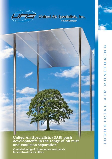
<strong>United</strong> <strong>Air</strong> <strong>Specialists</strong> (<strong>UAS</strong>) push<br />
developments in the range of oil mist<br />
and emulsion separation<br />
Commissioning of ultra-modern test bench<br />
for electrostatic air filters<br />
I N D U S T R I A L A I R M O N I T O R I N G<br />
17
<strong>United</strong> <strong>Air</strong> <strong>Specialists</strong> (<strong>UAS</strong>) push developments in the range of oil mist<br />
and emulsion separation<br />
Commissioning of ultra-modern test bench for electrostatic air filters<br />
1st issue 05-2009<br />
Imprint<br />
Authors:<br />
Carlo Saling, product manager, <strong>UAS</strong> <strong>United</strong> <strong>Air</strong> <strong>Specialists</strong> <strong>Inc</strong>.<br />
Gerd Munder, head of production department, <strong>UAS</strong> <strong>United</strong> <strong>Air</strong> <strong>Specialists</strong> <strong>Inc</strong>.<br />
Editor:<br />
<strong>UAS</strong> <strong>United</strong> <strong>Air</strong> <strong>Specialists</strong> <strong>Inc</strong>., Branch Office Germany<br />
Otto-Hahn-Str. 6 | DE-65520 Bad Camberg<br />
Phone +49 (0) 64 34 / 94 22-0 | Fax -99<br />
www.uas-inc.de<br />
Layout:<br />
IHW Jörn Jacobs & Co.<br />
Otto-Hahn-Str. 15 | DE-65520 Bad Camberg<br />
www.ihw-marketing.eu<br />
Copy, also in extracts, only permitted if consented by the editor.<br />
2
<strong>United</strong> <strong>Air</strong> <strong>Specialists</strong> (<strong>UAS</strong>) push developments<br />
in the range of oil mist and emulsion separation<br />
Commissioning of ultra-modern test bench for electrostatic<br />
air filters<br />
In Germany, coolants are used [1]<br />
in about 200,000 metal-working<br />
shops in the scope of chipping<br />
and chipless production processes.<br />
They are indispensable in metal<br />
working and processing. On the<br />
other hand, coolants bear health<br />
hazards for the people involved in<br />
the process when handled carelessly.<br />
Coolants (KSS) are deemed liquids<br />
which are used in the production<br />
processes of chipless processing,<br />
cutting and machining of materials.<br />
In the production processes,<br />
they cool the tool, reduce friction<br />
between workpiece and tool and<br />
wear of the tool, and/or remove<br />
chips among others.<br />
The variety of applications results<br />
in many types and different<br />
compositions of the coolants.<br />
Coolants can be classified as<br />
shown in the following figure: The<br />
coolants in their original state are<br />
defined as primary substance; the<br />
secondary substances are developed<br />
unintentionally during use<br />
and/or are added.<br />
[1] VDMA “Cooling lubricants - Fresh air at the<br />
workplace“, trade association “General ventilation“,<br />
team ”Aerosols“<br />
Coolants<br />
Non-water-miscible coolants<br />
(in the past also: cutting oil, grinding oil,<br />
drilling oil)<br />
Water-miscible coolants<br />
e.g. oil-water emulsion<br />
(in the past also: diluted soluble oil,<br />
drilling milk)<br />
Basic materials<br />
Attendant materials<br />
Additives<br />
Reaction products<br />
Foreign matters<br />
Microorganisms<br />
Primary substances<br />
Secondary substances<br />
Coolants<br />
3
<strong>United</strong> <strong>Air</strong> <strong>Specialists</strong> (<strong>UAS</strong>) force development work<br />
Hazards involved with coolants [2]<br />
In addition to the general impurities<br />
at the workplace, vapour,<br />
smoke, and aerosols are formed in<br />
the ambient air of liquid coolants. [2]<br />
This involves the hazard that particles<br />
may affect the operator while<br />
the following mechanisms occur:<br />
Absorption through respiratory<br />
system:<br />
Only a small par t of drops<br />
contained in aerosols with a<br />
diameter of more than 100 µm is<br />
normally inhaled. Whereas particles<br />
with a diameter of less than<br />
5 µm reach the lower respiratory<br />
tracts. Drops with a diameter of<br />
2 to 2.5 µm even penetrate the<br />
alveoli.<br />
Absorption via digestive tract:<br />
Bigger drops deposit in the nose,<br />
windpipe, and bronchial tubes and<br />
can thus also be swallowed<br />
Skin contact:<br />
The natural protective function of<br />
the skin is impaired<br />
As a consequence of the above<br />
described mechanisms, the following<br />
effects on the human body<br />
may occur:<br />
[2] VDMA “Cooling lubricants - Fresh air at the<br />
workplace“, trade association “General ventilation“,<br />
team “Aerosols“<br />
Irritant effects:<br />
Irritation of skin, respiratory tracts,<br />
and mucous membranes, conjunctivitis,<br />
vertigo, stimulation, possibly<br />
euphoria<br />
Allergenic effects:<br />
Toxic-degenerative contact eczema,<br />
allergic contact eczema, rarely<br />
bronchial asthma<br />
Toxic effects:<br />
Alterations of organs, impairment<br />
of nerves by absorption of<br />
substances through skin<br />
Carcinogenic effects:<br />
Formation of different types of<br />
cancer as well as tumours of brain<br />
and respiratory system<br />
Mutagenic effects:<br />
Gene mutation by mist of nonwater-miscible<br />
coolants and nitrosamines<br />
Further health hazards may be<br />
involved by microorganisms which<br />
preferably settle in water-mixed<br />
coolants. These microorganisms<br />
are mainly connected to aerosols<br />
and this is why an efficient separation<br />
of aerosols is compulsory.<br />
Germs and funguses may result<br />
in weakening of the body‘s own<br />
immune system and cause general<br />
diseases.<br />
4
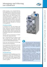
Continuous further development and research for<br />
improved separation of coolants – why?<br />
For some years, modern machining<br />
centres and machine tools have<br />
been showing a tendency towards<br />
ever increasing shaft power and<br />
chipping speeds resulting in higher<br />
emissions of pollutants and smaller<br />
particles.<br />
Due to the fact of progressing<br />
development in machining, further<br />
research is also required in the<br />
separation of coolants in order<br />
to ensure work protection under<br />
changing technical framework<br />
conditions also in future.<br />
Seen from this angle, the Company<br />
<strong>United</strong> <strong>Air</strong> <strong>Specialists</strong> <strong>Inc</strong>. successfully<br />
commissioned an ultramodern<br />
test bench at their site in Bad<br />
Camberg in Germany in spring<br />
2009 in order to boost its research<br />
activities in the range of electrostatic<br />
and mechanic oil mist and<br />
emulsion filters for the separation<br />
of coolants.<br />
Figure 1: Picture of test bench<br />
5
<strong>United</strong> <strong>Air</strong> <strong>Specialists</strong> (<strong>UAS</strong>) force development work<br />
Design of test area<br />
The constructional drawing illustrates the design of the test bench.<br />
7<br />
6<br />
2<br />
3<br />
1<br />
1 Aerosol generator<br />
2 Isokinetic sampling<br />
3 Aerosol spectrometer<br />
5<br />
4<br />
4 Filter (here: two-step electrostatic filter)<br />
5 Fan<br />
6 Control cabinet with frequency converter<br />
7 Flow meter<br />
Figure 2: 3D constructional drawing of test bench<br />
The aerosol generator (type PLG<br />
2300 by Palas), which complies<br />
with the requirements of VDI<br />
directive 3491, produces finest<br />
mist of liquids (coolants) which is<br />
introduced in the air flow of the<br />
test bench. The generator uses<br />
the Laskin principle: One nozzle<br />
atomises a test medium (e.g. coolant<br />
diethylhexyl Sebacat (DEHS)<br />
or dioctylphthalate (DOP)) by<br />
means of compressed air from the<br />
in-house mains.<br />
To be able to produce high<br />
concentrations of aerosol of up to<br />
100 mg/m³ in the test bench, the<br />
primary pressure of compressed<br />
air can be set by means of a needle<br />
valve (1-8 bar ü) and the temperature<br />
of the test medium can be set<br />
in the liquid container inside the<br />
generator (20-80 °C).<br />
The nominal temperature of the<br />
test medium is set to the desired<br />
temperature using a temperature<br />
probe. Furthermore, a sensor<br />
monitors the liquid level in the<br />
container activating a hose pump<br />
to fill the container automatically if<br />
the limit is fallen short of for being<br />
able to perform long-term measurements<br />
of the filter in the test<br />
bench as well.<br />
6
Figure 3 shows a typical emission<br />
spectrum of the aerosol generator.<br />
The particle spectrum - measured<br />
with the lubricant DEHS<br />
- is subject to the Gaussian normal<br />
distribution curve; the median of<br />
the number of particles amounts<br />
to 0,3 – 0,4 µm. When commissioning<br />
the plant, it was demonstrated<br />
that the number as well<br />
as the distribution of particles<br />
are constant regarding time and<br />
are reproducible under equal<br />
test conditions. This particle spectrum<br />
corresponds to the results<br />
obtained with modern machine<br />
tools (lathes, milling machines, and<br />
grinding machines) with high shaft<br />
power and thus reflects actual<br />
operating conditions [3] .<br />
[3] “Exhaust and filtration of metal working<br />
fluids emissions on machine tools“ by German<br />
Federation of institutions for statutory accident<br />
insurance and prevention (HVBG), ISBN 3-88383-<br />
714-8, November 2006<br />
The samples are taken from the<br />
piping in an isokinetic way, i.e. a<br />
part of the air flow is soaked up<br />
by a nozzle and conveyed to the<br />
particle sensor at the same speed.<br />
The nozzles are made of stainless<br />
steel and comply with the European<br />
Standard EN 13284-1 [4] .<br />
In addition, samples are taken<br />
using electrically conductive plastic<br />
hoses in order to prevent separation<br />
by electrostatic charge in the<br />
hoses. Furthermore, it was seen<br />
to it that the track where samples<br />
were taken was vertical and short<br />
in order to prevent coarser particles<br />
from depositing or segregating.<br />
[4] VDI directive 2066: “Particulate matter measurement<br />
- Dust measurement in flowing gases<br />
- Gravimetric determination of dust load“, Beuth<br />
Verlag, November 2006<br />
Figure 3: Particle spectrum of aerosol generator (DEHS)<br />
Note: Distribution, absolute number of particles and time constancy<br />
7
<strong>United</strong> <strong>Air</strong> <strong>Specialists</strong> (<strong>UAS</strong>) force development work<br />
Figure 4: Isokinetic nozzles<br />
The sample gas volume is controlled<br />
and monitored by the control<br />
electronics (type welas 3000 by<br />
Palas). The particles are measured<br />
by optical white light aerosol<br />
spectrometers (type welas 3000<br />
by Palas). The particle diameter<br />
is defined using the intensity of<br />
scattered light and the pulses are<br />
counted over a specified period for<br />
the purpose of obtaining a statistic<br />
confidence level of the results.<br />
We obtain a distribution histogram<br />
with high resolution (cf. figure 3)<br />
which illustrates the number of<br />
particles of the samples as a function<br />
of the diameter. This histogram<br />
permits the measurement<br />
of fractional filtration efficiencies<br />
when a sensor is used on both the<br />
crude gas and the clean gas side.<br />
When measuring the particles,<br />
typical sources of error such as<br />
border-zone or coincidence errors<br />
are eliminated thanks to the white<br />
light source, 90° scattered light<br />
detection, and T-stop technology.<br />
White light aerosol spectrometers<br />
measure concentrations of up to<br />
100,000 particles per cm³. As the<br />
filter elements in the test field<br />
can also be subjected to extremely<br />
high pollutant concentrations<br />
Important for sampling:<br />
Isokinetics<br />
Suction from the gas flow in the<br />
pipe is effected at equal speed<br />
(isokinetic). Thus, a precise concentration<br />
can be measured. In case of<br />
suction at higher speed (hyperkinetic)<br />
the measured concentration<br />
would be lower than the actual<br />
concentration due to inertness of<br />
particles. On the other hand, the<br />
measured concentration would<br />
be higher than the actual concentration<br />
in case of suction at lower<br />
speed (hypokinetic).<br />
8
of up to 100 mg/m³ which may<br />
be produced by modern machine<br />
tools with high shaft power, the<br />
sample gas on the crude gas side<br />
is to be diluted correspondingly<br />
using a dilution system (type DC<br />
10000 iP by Palas) and a side channel<br />
blower (type SE3 by Elektror).<br />
The dilution factor is considered<br />
automatically in the calculation of<br />
the crude gas concentration. The<br />
error of measurement caused by<br />
the dilution system is < 5 %.<br />
The test bench serves the testing<br />
of filters with electrostatic and<br />
mechanic filter elements. They can<br />
be tested optionally either with or<br />
without pre-filter.<br />
The directly driven fan controls<br />
the volume flow by means of a<br />
frequency converter (type Varispeed<br />
E7 by Omron) and maintains<br />
the desired nominal value<br />
(frequency). The latter is matched<br />
with the actual value through a<br />
Vortex flow meter (type VA40 by<br />
Höntzsch) which is factory-calibrated.<br />
This calibration was checked<br />
using a Prandtl flow pipe (type<br />
Mano<strong>Air</strong> by Schiltknecht). The<br />
square coefficient of correlation<br />
of the characteristic curve amounts<br />
to R² = 0.999. To provide reliability,<br />
calibration is verified at regular<br />
intervals.<br />
The pressure loss of the filter<br />
elements – in particular essential<br />
for mechanic filter systems –<br />
can be recorded and monitored<br />
by a differential pressure sensor.<br />
A digital meteorological station<br />
(temperature, relative humidity of<br />
air) records the climatic conditions<br />
in the laboratory.<br />
In a next step, the test bench will<br />
be provided with a digital oscilloscope<br />
to effect high-frequency<br />
measurements (current and voltage)<br />
of the ioniser and collector<br />
in the electrostatic separator.<br />
Valuable conclusions can then be<br />
drawn regarding long-term tests of<br />
prototypes. Furthermore, emulsion<br />
measurements are planned. This<br />
requires an insulation/temperature<br />
setting of the test bench.<br />
9
Collecting efficiency (%)<br />
<strong>United</strong> <strong>Air</strong> <strong>Specialists</strong> (<strong>UAS</strong>) force development work<br />
Summary<br />
100<br />
The test bench allows testing and<br />
further development of electrostatic<br />
and mechanic filter cells<br />
according to pertinent directives.<br />
Original cells can be tested<br />
whilst excluding errors of measurement<br />
as a consequence of<br />
down-scaling of test filters.[5]<br />
When designing the test bench it<br />
was taken into consideration that<br />
even extreme pollution loads of<br />
up to 100 mg/m³ can be measured<br />
and fractional filtration efficiencies<br />
in the lower sub-micrometer range<br />
(0.3 to 10 µm) can be determined.<br />
By indicating the total gravimetric<br />
filtration efficiency – as usual in<br />
Figure: Alveolar fraction (A fraction)<br />
Mass fraction of inhaled particles which penetrates the respiratory tracts (alveoli)<br />
practice – the quality of a filter<br />
cannot be evaluated sufficiently<br />
and misinterpretations may result<br />
therefrom.<br />
Thus the test bench also satisfies<br />
the requirements of modern<br />
machine tools regarding pollutant<br />
concentrations and particle spectrums<br />
with which work pieces are<br />
machined at high shaft power [6] .<br />
In particular, aerosols which are<br />
smaller than 1-2 µm and cannot be<br />
seen with the naked eye present<br />
the highest hazards for employees<br />
for these particles penetrate<br />
the alveoli and thus get into the<br />
DIN EN 481<br />
not respirable<br />
50<br />
Tracheo<br />
bronchial<br />
dust<br />
Nose, throat,<br />
larynx dust<br />
alveolar<br />
penetrating the thorax<br />
respirable<br />
10<br />
1<br />
2 5 10 20 50 100<br />
Aerodynamic particle diameter (µm)<br />
Figure 5:<br />
Total efficiency (hazard) as a function of particle diameter [6]<br />
[5] “DIN EN 481 – Directive: Workplaces atmospheres;<br />
size fraction definitions for measurement<br />
of airborne particles“, Beuth Verlag, 1993<br />
[6] “Exhaust and filtration of metal working fluids<br />
emissions on machine tools“ by German Federation<br />
of institutions for statutory accident insurance<br />
and prevention (HVBG), ISBN 3-88383-714-8,<br />
November 2006<br />
10
loodstream. A precise size cannot<br />
be indicated for these particles but<br />
only a size distribution.<br />
This range is described in DIN<br />
EN 481 (cf. figure 5). The shown<br />
curve for the A fraction thus illustrates<br />
the probability of a particle<br />
of a certain aerodynamic diameter<br />
depositing in the alveoli [7] . Thanks<br />
to the test bench we are able to<br />
focus on the separation of these<br />
fine and hazardous particles which<br />
cannot be measured with conventional<br />
portable meters.<br />
Last but not least, the test bench<br />
permits the in-house development<br />
of tailored solutions for machine<br />
tool manufacturers in order to<br />
present effective and efficient<br />
filter systems.<br />
[7] “Was ist Staub“, informative page under<br />
http://www.bgglaskeramik.de/d/staub-info/<br />
definition/index.html by BG Glas und Keramik<br />
(German trade association for glass and ceramics)<br />
11
<strong>United</strong> <strong>Air</strong> <strong>Specialists</strong> (<strong>UAS</strong>) force development work<br />
Notes<br />
12
Notes<br />
13
Zweigniederlassung Deutschland:<br />
Otto-Hahn-Str. 6 | 65520 Bad Camberg<br />
Tel. +49 (0) 64 34 / 94 22-0 | Telefax -99 | info@uas-inc.de | www.uas-inc.de<br />
Büro Nord:<br />
RHB oHG | Kronskamp 134 | 22880 Wedel<br />
Telefon +49 (0) 41 03/ 90 48 60 | Telefax +49 (0) 41 03/ 90 48 66<br />
Büro Nordrhein-Westfalen:<br />
Auf dem Eigen 2 | 42349 Wuppertal<br />
Telefon +49 (0) 2 02 / 2 47 81 40 | Telefax 2 47 81 66<br />
Büro Mitte:<br />
Dehrner Straße 12a | 65554 Limburg<br />
Telefon +49 (0) 64 33 / 70 06 36 | Telefax 81 33 3<br />
Büro Sachsen:<br />
Daubaer Straße 20 | 01847 Lohmen<br />
Telefon +49 (0) 35 01 / 58 83 44 | Telefax 58 81 97<br />
Büro Baden-Württemberg / Bayern:<br />
Büchel GmbH | Breite Str. 27 | 89168 Niederstotzingen<br />
Tel. +49 (0) 73 25 / 96 05 0 | Telefax 96 05 80<br />
Büro Österreich:<br />
Hallestraße 29 | 4030 Linz | Telefon +43 (0)7 32 / 31 38 13 | Telefax 30 44 89<br />
14