SE-3000 Instruction Manual - Datavideo
SE-3000 Instruction Manual - Datavideo
SE-3000 Instruction Manual - Datavideo

You also want an ePaper? Increase the reach of your titles
YUMPU automatically turns print PDFs into web optimized ePapers that Google loves.
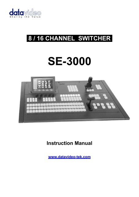
.8 / 16 CHANNEL SWITCHER.<br />
<strong>SE</strong>-<strong>3000</strong><br />
<strong>Instruction</strong> <strong>Manual</strong><br />
www.datavideo-tek.com
Table of contents<br />
Warnings and Precautions ....................................................................................................... 6<br />
Warranty .................................................................................................................................... 7<br />
Standard Warranty ........................................................................................................... 7<br />
Two Year Warranty .......................................................................................................... 7<br />
Disposal ..................................................................................................................................... 7<br />
For EU Customers only - WEEE Marking. ........................................................................ 7<br />
Packing List ............................................................................................................................... 7<br />
Introduction ............................................................................................................................... 8<br />
Features ........................................................................................................................... 9<br />
Main Unit.................................................................................................................................. 10<br />
Front Panel .................................................................................................................... 10<br />
Rear Panel ..................................................................................................................... 10<br />
Control Panel .......................................................................................................................... 10<br />
Keyboard ....................................................................................................................... 10<br />
Keyboard Rear ............................................................................................................... 10<br />
Input & Output Connections – Main Unit ............................................................................... 11<br />
Control Panel to Main Unit Ethernet Connection .................................................................. 13<br />
Power ....................................................................................................................................... 13<br />
Main Unit ........................................................................................................................ 13<br />
Control Panel ................................................................................................................. 13<br />
Video Connections ................................................................................................................. 14<br />
SDI Video Inputs ............................................................................................................ 14<br />
Setting the Resolution of the <strong>SE</strong>-<strong>3000</strong> ................................................................................... 14<br />
DVI Input – Input 8 ...................................................................................................... 15<br />
Input Channels 9~16 ................................................................................................... 15<br />
Video Outputs ......................................................................................................................... 16<br />
Auxiliary HD-SDI Outputs 1~4 ..................................................................................... 16<br />
How to assign Auxiliary Output sources ...................................................................... 16<br />
Monitor Connections .............................................................................................................. 17<br />
Multi Image Preview ....................................................................................................... 17<br />
Multi Image Preview – Initial Set Up ............................................................................... 17<br />
Modifying the chosen MultiViewer Layout ...................................................................... 18<br />
Changing Main Screens 1~4 ....................................................................................... 18<br />
Modifying the Multi Image Preview Labels ................................................................... 19<br />
Source Select Button Group .................................................................................................. 20<br />
Aux Bus – Top Button Row ............................................................................................ 20<br />
Program – Middle Button Row ....................................................................................... 20<br />
Preset – Bottom Button Row .......................................................................................... 20<br />
Transitions Group ................................................................................................................... 20<br />
AUTO TRANS Button ..................................................................................................... 20<br />
CUT Button .................................................................................................................... 20<br />
MIX Button ..................................................................................................................... 20<br />
WIPE Button .................................................................................................................. 21<br />
DVE Button .................................................................................................................... 21<br />
2
Previewing a selected transition ............................................................................................ 21<br />
REV and NORM / REV buttons ...................................................................................... 21<br />
WIPE Selection Menu.............................................................................................................. 22<br />
Wipe .............................................................................................................................. 22<br />
Soft Value ................................................................................................................... 22<br />
Width Value ................................................................................................................. 23<br />
Level Value ................................................................................................................. 23<br />
Soft Balance ................................................................................................................ 23<br />
Wipe Border ................................................................................................................... 23<br />
Colour Palette ............................................................................................................. 23<br />
Hue, Sat and Luma values .......................................................................................... 23<br />
Source Control ............................................................................................................ 23<br />
Wipe Shade ................................................................................................................... 24<br />
Colour Palette ............................................................................................................. 24<br />
Hue, Sat and Luma values .......................................................................................... 24<br />
Shade Soft .................................................................................................................. 24<br />
Shade Position ............................................................................................................ 24<br />
Wipe Position ................................................................................................................. 24<br />
DVE Transitions Menu ............................................................................................................ 25<br />
Transition Selection........................................................................................................ 25<br />
Home Menu – Length of Transition ........................................................................................ 25<br />
ME Trans ....................................................................................................................... 25<br />
DSK Trans ..................................................................................................................... 25<br />
FTB Trans ...................................................................................................................... 25<br />
Freeze Menu ............................................................................................................................ 26<br />
Freeze On / Off .............................................................................................................. 26<br />
Mode .............................................................................................................................. 26<br />
Stills Menu ............................................................................................................................... 27<br />
Grabbing & Saving a Still to memory .............................................................................. 27<br />
Loading an existing Still from memory ............................................................................ 28<br />
Deleting a saved Still from memory ............................................................................. 28<br />
Bus Matte Menu ...................................................................................................................... 29<br />
Colour Palette ................................................................................................................ 29<br />
Hue, Sat and Luma values ............................................................................................. 29<br />
Storing and Recalling U<strong>SE</strong>R Set Ups .................................................................................... 30<br />
How to quickly save a User Set Up ................................................................................ 30<br />
Labelling an existing User memory slot ....................................................................... 30<br />
Loading a previously saved User Set Up ........................................................................ 31<br />
Deleting a User Set Up ................................................................................................ 31<br />
Flex Overview ...................................................................................................................... 31<br />
Flex screen order........................................................................................................ 32<br />
Saving the Flex set up ................................................................................................ 32<br />
Flex Set Up Menus ..................................................................................................... 32<br />
Flex Source Select .............................................................................................................. 33<br />
Flex DVE1 (PiP1) and DVE2 (PiP2) ......................................................................................... 33<br />
DVE Position .................................................................................................................. 33<br />
The Enable option ....................................................................................................... 33<br />
3
The Rotation value ...................................................................................................... 33<br />
The X and Y values ..................................................................................................... 33<br />
The Z value ................................................................................................................. 34<br />
DVE Size ....................................................................................................................... 34<br />
The Z value of DVE Size ............................................................................................. 34<br />
The Soft value of DVE Size ......................................................................................... 34<br />
DVE Border .................................................................................................................... 34<br />
Hue, Sat and Luma values .......................................................................................... 34<br />
Size ............................................................................................................................. 34<br />
Soft ............................................................................................................................. 34<br />
DVE Crop ....................................................................................................................... 35<br />
Left, Right, Top and Bottom edge ................................................................................ 35<br />
The Size value ............................................................................................................ 35<br />
Flex Keyer Menu .................................................................................................................. 35<br />
Flex Key and Fill Example CG-350 Set Up ................................................................. 36<br />
Chroma Key Overview ............................................................................................................ 37<br />
A good foreground image helps produce a good key ..................................................... 37<br />
Three Chip Camera ..................................................................................................... 37<br />
Do not mix SD and HD standards when keying ........................................................... 37<br />
White Balance the Camera .......................................................................................... 37<br />
Lighting ....................................................................................................................... 38<br />
Control Panel Button Groups used ................................................................................. 38<br />
Chroma Key Quick Set Up ...................................................................................................... 39<br />
Chroma Matte ................................................................................................................ 40<br />
Chroma Key Ctrl ............................................................................................................ 40<br />
Key Acceptance .......................................................................................................... 40<br />
Key Lift ........................................................................................................................ 40<br />
Key Gain ..................................................................................................................... 40<br />
Color Spill ...................................................................................................................... 41<br />
Chroma Acceptance .................................................................................................... 41<br />
Chroma Suppress ....................................................................................................... 41<br />
Saving the Chroma Key set up ....................................................................................... 41<br />
Luma Key Overview ................................................................................................................ 41<br />
Luma Key Quick Set Up .......................................................................................................... 42<br />
Luma Key – Lift .............................................................................................................. 43<br />
Luma Key – Gain ........................................................................................................... 43<br />
Luma Key – Opacity .................................................................................................... 43<br />
Luma Key – Invert ....................................................................................................... 43<br />
LIN Button ................................................................................................................... 43<br />
<strong>SE</strong>LF Button ................................................................................................................ 43<br />
TOP Button ................................................................................................................. 43<br />
Saving the Luma Key set up .......................................................................................... 43<br />
Mask Menu .............................................................................................................................. 44<br />
Keyer Matte ............................................................................................................................. 45<br />
Colour Palette ................................................................................................................ 45<br />
The Hue adjustment .................................................................................................... 45<br />
4
The Sat or Saturation value ......................................................................................... 45<br />
The Luma value .......................................................................................................... 45<br />
Using Key 1 and Key 2 ............................................................................................................ 46<br />
Transition Controls ......................................................................................................... 46<br />
BGND - Background .................................................................................................... 46<br />
KEY1 / KEY2 ............................................................................................................... 46<br />
Priority Button .............................................................................................................. 47<br />
Previewing a selected transition .................................................................................. 47<br />
REV and NORM / REV buttons ................................................................................... 47<br />
DSK1 and DSK2 Quick Set Up ............................................................................................... 48<br />
Saving the DSK1 DSK2 set up ....................................................................................... 49<br />
<strong>SE</strong>-<strong>3000</strong> Keying layers ............................................................................................................ 49<br />
DSK Transitions .......................................................................................................... 49<br />
Looping an External reference through the <strong>SE</strong>-<strong>3000</strong> ........................................................... 50<br />
Tally Output ............................................................................................................................. 51<br />
Tally connection to two ITC-100 units ............................................................................ 52<br />
Features awaiting firmware development ............................................................................. 53<br />
Clip Menu ....................................................................................................................... 53<br />
Audio Menu .................................................................................................................... 53<br />
GPI connection .............................................................................................................. 53<br />
RS-232........................................................................................................................... 53<br />
RS-422 IN ...................................................................................................................... 54<br />
RS-422 OUT .................................................................................................................. 54<br />
Updating the <strong>SE</strong>-<strong>3000</strong> firmware ............................................................................................. 55<br />
Checking Firmware Revisions ........................................................................................ 56<br />
Drawing Control Panel & Main Unit ....................................................................................... 56<br />
Specifications ......................................................................................................................... 57<br />
Service and Support ............................................................................................................... 58<br />
Disclaimer of Product and Services<br />
The information offered in this instruction manual is intended as a guide only. At all times, <strong>Datavideo</strong> Technologies will try to give correct,<br />
complete and suitable information. However, <strong>Datavideo</strong> Technologies cannot exclude that some information in this manual, from time to<br />
time, may not be correct or may be incomplete. This manual may contain typing errors, omissions or incorrect information. <strong>Datavideo</strong><br />
Technologies always recommend that you double check the information in this document for accuracy before making any purchase<br />
decision or using the product. <strong>Datavideo</strong> Technologies is not responsible for any omissions or errors, or for any subsequent loss or<br />
damage caused by using the information contained within this manual. Further advice on the content of this manual or on the product<br />
can be obtained by contacting your local <strong>Datavideo</strong> Office or dealer.<br />
5
Warnings and Precautions<br />
1. Read all of these warnings and save them for later reference.<br />
2. Follow all warnings and instructions marked on this unit.<br />
3. Unplug this unit from the wall outlet before cleaning. Do not use liquid or aerosol cleaners. Use a<br />
damp cloth for cleaning.<br />
4. Do not use this unit in or near water.<br />
5. Do not place this unit on an unstable cart, stand, or table. The unit may fall, causing serious damage.<br />
6. Slots and openings on the cabinet top, back, and bottom are provided for ventilation. To ensure safe<br />
and reliable operation of this unit, and to protect it from overheating, do not block or cover these<br />
openings. Do not place this unit on a bed, sofa, rug, or similar surface, as the ventilation openings on<br />
the bottom of the cabinet will be blocked. This unit should never be placed near or over a heat<br />
register or radiator. This unit should not be placed in a built-in installation unless proper ventilation is<br />
provided.<br />
7. This product should only be operated from the type of power source indicated on the marking label<br />
of the AC adapter. If you are not sure of the type of power available, consult your <strong>Datavideo</strong> dealer or<br />
your local power company.<br />
8. Do not allow anything to rest on the power cord. Do not locate this unit where the power cord will be<br />
walked on, rolled over, or otherwise stressed.<br />
9. If an extension cord must be used with this unit, make sure that the total of the ampere ratings on the<br />
products plugged into the extension cord do not exceed the extension cord rating.<br />
10. Make sure that the total amperes of all the units that are plugged into a single wall outlet do not<br />
exceed 15 amperes.<br />
11. Never push objects of any kind into this unit through the cabinet ventilation slots, as they may touch<br />
dangerous voltage points or short out parts that could result in risk of fire or electric shock. Never<br />
spill liquid of any kind onto or into this unit.<br />
12. Except as specifically explained elsewhere in this manual, do not attempt to service this product<br />
yourself. Opening or removing covers that are marked “Do Not Remove” may expose you to<br />
dangerous voltage points or other risks, and will void your warranty. Refer all service issues to<br />
qualified service personnel.<br />
13. Unplug this product from the wall outlet and refer to qualified service personnel under the following<br />
conditions:<br />
a. When the power cord is damaged or frayed;<br />
b. When liquid has spilled into the unit;<br />
c. When the product has been exposed to rain or water;<br />
d. When the product does not operate normally under normal operating conditions. Adjust only<br />
those controls that are covered by the operating instructions in this manual; improper<br />
adjustment of other controls may result in damage to the unit and may often require<br />
extensive work by a qualified technician to restore the unit to normal operation;<br />
e. When the product has been dropped or the cabinet has been damaged;<br />
f. When the product exhibits a distinct change in performance, indicating a need for service.<br />
6
Warranty<br />
Standard Warranty<br />
• <strong>Datavideo</strong> equipment is guaranteed against any manufacturing defects for one year from the date of<br />
purchase.<br />
• The original purchase invoice or other documentary evidence should be supplied at the time of any<br />
request for repair under warranty.<br />
• Damage caused by accident, misuse, unauthorized repairs, sand, grit or water is not covered by this<br />
warranty.<br />
• All mail or transportation costs including insurance are at the expense of the owner.<br />
• All other claims of any nature are not covered.<br />
• Cables & batteries are not covered under warranty.<br />
• Warranty only valid within the country or region of purchase.<br />
• Your statutory rights are not affected.<br />
Two Year Warranty<br />
• All <strong>Datavideo</strong> products purchased after 01-Oct.-2008 qualify for a free one year extension to the<br />
standard Warranty, providing the product is registered with <strong>Datavideo</strong> within 30 days of purchase. For<br />
information on how to register please visit www.datavideo-tek.com or contact your local <strong>Datavideo</strong><br />
office or authorized Distributors<br />
• Certain parts with limited lifetime expectancy such as LCD Panels, DVD Drives, Hard Drives are only<br />
covered for the first 10,000 hours, or 1 year (whichever comes first).<br />
Any second year warranty claims must be made to your local <strong>Datavideo</strong> office or one of its authorized<br />
Distributors before the extended warranty expires.<br />
Disposal<br />
For EU Customers only - WEEE Marking.<br />
This symbol on the product indicates that it will not be treated as household waste. It must<br />
be handed over to the applicable take-back scheme for the recycling of Waste Electrical and<br />
Electronic Equipment. For more detailed information about the recycling of this product,<br />
please contact your local <strong>Datavideo</strong> office.<br />
Packing List<br />
The following items should be included in the box. If any items are missing please contact your supplier.<br />
Item No. Description Quantity<br />
1 <strong>SE</strong>-<strong>3000</strong> Main Unit 1<br />
2 <strong>SE</strong>-<strong>3000</strong> Control Panel / Keyboard 1<br />
3 AC Power Cord 2<br />
4 Ethernet Cable 8P-8P 3m 1<br />
5 4pin XLR Switch Mode Power Supply DC 12V 10A 1<br />
6 4pin XLR Switch Mode Power Supply DC 12V 5A 1<br />
7 USB cable 1<br />
8 <strong>SE</strong>-<strong>3000</strong> <strong>Instruction</strong> <strong>Manual</strong> 1<br />
7
Introduction<br />
The <strong>Datavideo</strong> <strong>SE</strong>-<strong>3000</strong> is a professional, eight or sixteen channel High Definition SDI Video Switcher. The<br />
<strong>SE</strong>-<strong>3000</strong>’s modular design allows the Main unit (2U high) to be mounted in a standard 19” rack. The Control<br />
unit can then be placed on a nearby flat work surface or built into a gallery or OB van desk. The Control<br />
Panel and Main unit communicate via a standard (straight through) Ethernet patch cable.<br />
The switcher can be supplied with eight inputs and then be upgraded to sixteen channels at a later date.<br />
Alternatively the switcher can be purchased with all sixteen input channels already present. The <strong>SE</strong>-<strong>3000</strong><br />
Main unit can accept HD-SDI inputs and one DVI-D source input (channels 1~8). If you have purchased the<br />
sixteen channel version then inputs 9~16 also have the option to upscale four SD-SDI inputs to your chosen<br />
HD standard.<br />
The <strong>SE</strong>-<strong>3000</strong>’s built in TBCs can synchronise the input channels internally without the need for external<br />
genlock; although you can choose to loop an external reference through the <strong>SE</strong>-<strong>3000</strong> if you wish to minimise<br />
the delay through the switcher. Each input channel is also provided with its own Colour Processor or Proc<br />
Amp.<br />
The <strong>SE</strong>-<strong>3000</strong> Multi Image Preview, via DVI-D or HD-SDI (BNC), can be fed to one or two large format LCD<br />
monitor screens, this helps keep the number of required monitors to a minimum. The <strong>SE</strong>-<strong>3000</strong> can also<br />
provide four user delegated Auxiliary HD-SDI outputs, as well as providing HD Preview and Program outputs<br />
via HD-SDI (BNC) and Component (Y, Pb, Pr).<br />
Normal mixer features such as Picture in Picture (PiP) as well as Cut, Wipe and Mix (dissolve) transitions are<br />
available. On top of these the <strong>SE</strong>-<strong>3000</strong> can perform advanced Digital Video Effects (DVE) such as 3D page<br />
turn transitions and even produce a multi image FLEX output with key and fill layers.<br />
The user defined FLEX output allows a choice of background image/video plus two optional PiPs which<br />
can be sized, rotated, positioned and cropped. Either PiP window can also have user defined coloured<br />
borders too.<br />
The <strong>SE</strong>-<strong>3000</strong> can be configured to allow paired video channels of foreground and background to provide<br />
Chroma or Luma keyed video outputs thus giving the option to create productions with a virtual studio feel.<br />
Up to 100 still images can captured from live video and stored in non-volatile memory for later inclusion in a<br />
project. User set ups can be defined and saved using the Control Panel Keyboard and Joystick or its 7” LCD<br />
touch screen menu panel.<br />
Up to 1000 set ups (M/Es) can be stored in to the onboard user memory slots and recalled instantly at the<br />
press of a button using the user/shot box area of the control panel.<br />
The <strong>SE</strong>-<strong>3000</strong> can provide simple tally communication which can be easily incorporated into the <strong>Datavideo</strong><br />
ITC-100 based talk back system or a bespoke tally light set up. Redundant connections for GPI, RS-232 and<br />
RS-422 are also provided so they can be incorporated into later firmware versions.<br />
All in all the <strong>SE</strong>-<strong>3000</strong> provides the right tools to light your creative imagination and meet your HD workflow<br />
needs. Push your live HD production envelope further and at lower cost than ever before.<br />
That’s <strong>Datavideo</strong>; sharing the value!<br />
8
Features<br />
• Up to 16 HD SDI Inputs (8 or 16 Inputs)<br />
• Built-in SD-to-HD up converters for up to 4 sources simultaneously (inputs 9~16)<br />
• Built-in frame syncs for each input<br />
• Dedicated DVI Input (treated as input 8 via a menu option)<br />
• Multi-image preview or Preview or Program output via DVI-D<br />
• 1 M/E Switcher<br />
• 4 Keyers (2 in Mix and Effect, 2 as DSK/ Down Stream Key)<br />
• 2 Chroma Keyers in Mix and Effect<br />
• 30+ Wipe Patterns, with variable border width, source/colour, softness<br />
• Built-in DVE transition engine, with 80+ transitions including page turns<br />
• FLEX - Dual Channel P-in-P Processor with Background & Keyer<br />
• Program (PGM), Preview (PVW), Program +DSK, Preview +DSK outputs available<br />
• HD Component and down converted SD Component output as well as HD-SDI output<br />
• 4 user delegated auxiliary HD-SDI outputs<br />
• Store up to 100 still images<br />
• Up to 1000 set ups (M/Es) can be stored in to the onboard user memory slots<br />
• Ergonomic, intuitive control panel for quick and easy operation<br />
• Large 7” touch-screen LCD panel on control unit for easy menu navigation and setting changes<br />
• PC Ethernet based control interface software available<br />
• Planned update(s) for RS-232, RS-422 and GPI controls<br />
• Planned update(s) for Audio and Clip menus<br />
• Separate, 2U high, 19” rack mountable Main unit<br />
• Proc Amp controls for black level, white stretch, white clip, Chroma gain for each input<br />
• Selectable mixer HD Standards 1080i (59.94, 60, 50) or 720p (59.94, 60, 50)<br />
9
Main Unit<br />
Front Panel<br />
The front panel of the <strong>SE</strong>-<strong>3000</strong> Main Unit has a ventilation plate; to prevent overheating please ensure that<br />
adequate airflow is provided. The Main Unit also comes with 19” rack mounts already fitted.<br />
Rear Panel<br />
Control Panel<br />
Keyboard<br />
Keyboard Rear<br />
10
Input & Output Connections – Main Unit<br />
Starting from the bottom left corner.<br />
SDI / HD-SDI Inputs 1~8 & 9 ~16<br />
The lower row of HD-SDI inputs are labelled 1~8. The upper row<br />
of SDI HD/SD inputs are labelled 9~16. If your unit has 8 inputs<br />
only then the upper row of BNC connectors will not be present.<br />
Units with only 8 inputs can be upgraded to 16 inputs, please<br />
speak with your local <strong>Datavideo</strong> supplier for availability and price.<br />
AUX Outputs 1~4<br />
4 user delegated HD-SDI Auxiliary outputs – see page 16.<br />
PGM & PVW Outputs<br />
HD-SDI Program (PGM) and Preview (PVW) outputs.<br />
MULTI-1 & MULTI-2 Outputs<br />
HD-SDI Multi Image Preview of input sources with PGM, PVW,<br />
Still Store 1 and 2 – see page 17.<br />
REF IN & REF LOOP<br />
Use these connections to loop external house sync through the<br />
<strong>SE</strong>-<strong>3000</strong> Mixer. See page 50.<br />
SD COMPONENT OUTPUT<br />
Downscaled SD Component (YPbPr / RGB) PGM output.<br />
HD COMPONENT OUTPUT<br />
HD Component (YPbPr / RGB) PGM output.<br />
DVI-D Input<br />
This input can accept signals from computer or laptop. A DVI-D to<br />
HDMI cable is required if connecting a HDMI source here.<br />
Any input needs to match the resolution of the mixer.<br />
DVI-D Output<br />
Can be set up to output Multi Image Preview, PGM or PVW<br />
Any Monitor connected needs to match the mixer resolution<br />
Ethernet Ports<br />
Used to connect the Main Unit to the Control Panel / Keyboard.<br />
An additional Ethernet port is provided so that the unit can be<br />
controlled remotely via PC software - see page 12.<br />
11
Starting from the Top left corner<br />
XLR Balanced Audio Inputs<br />
XLR Balanced Audio Outputs<br />
TALLY<br />
37 Pin D-Sub connector. See page 51 for more information.<br />
RS-422 IN & RS-422 OUT<br />
9 Pin D-Sub connector. See page 54 for more information.<br />
RS-232<br />
9 Pin D-Sub connector. See page 53 for more information.<br />
GPI<br />
15 Pin D-Sub connector. See page 53 for more information.<br />
DC Input 12V 10A<br />
Pin 1 = GND ( - )<br />
Pin 2 = NC<br />
Pin 3 = NC<br />
Pin 4 = VCC ( + )<br />
Case Earth Connector<br />
12
Control Panel to Main Unit Ethernet Connection<br />
The Control Panel / Keyboard<br />
communicates with the <strong>SE</strong>-<strong>3000</strong><br />
Main unit using the supplied 3m<br />
Ethernet (straight through) patch<br />
cable. There is one Ethernet port<br />
on the rear of the Control Panel /<br />
Keyboard and two Ethernet ports<br />
on the rear of the Main unit. Use<br />
any of these Ethernet ports for<br />
connecting the Control Panel to<br />
the Main unit.<br />
The Main Unit can also<br />
communicate over a simple Static<br />
IP PC network using a cross over Ethernet cable direct to a PC as shown above. In order to use this feature<br />
additional Windows based software is required. Please register your unit using the link below in order to<br />
receive this free application and the PC set up instructions.<br />
http://www.datavideo.info/en/productReg.php<br />
Please note; using the Ethernet connection across an existing DHCP network may delay communication<br />
with the mixer. The default IP address for the Control Panel is 192.168.1.115 and the Main unit is<br />
192.168.1.114. Both units can communicate with each other across an existing DHCP network but the IP<br />
addresses mentioned above need to be allowed on the network as static IP addresses. You may need the<br />
help of an I.T. specialist when setting up the DHCP server in this way otherwise conflicts may occur.<br />
Power<br />
Main Unit<br />
Connect the supplied 12V 10A power supply to the 4pin XLR DC Power Input on the rear of the Main Unit.<br />
The power supply should be connected to a suitable mains electric outlet using the supplied mains cable. A<br />
case earth connector is also provided.<br />
Control Panel<br />
The Control Panel has a 4pin XLR DC In socket on the rear panel, and a 12v 5A power supply is supplied. A<br />
case earth connector is also provided.<br />
There are two power ON/OFF switches to look at on the <strong>SE</strong>-<strong>3000</strong>, one on the Main unit and another on the<br />
Control Panel / Keyboard. Start the Main unit first and then the Control Panel.<br />
Main Unit On / Off Switch<br />
Control Panel On / Off Switch<br />
13
Video Connections<br />
SDI Video Inputs<br />
Looking at the rear panel of the <strong>SE</strong>-<strong>3000</strong> Main Unit, the lower<br />
row of HD-SDI inputs are labelled 1~8 and the upper row of<br />
SDI HD/SD inputs are labelled 9~16. If your unit only has 8<br />
inputs then the upper row of BNC connectors will not be<br />
present.<br />
Units with only 8 inputs can be upgraded to 16 inputs, please speak with your local <strong>Datavideo</strong> supplier for<br />
upgrade availability and price.<br />
Inputs 9~16 can be used to input Standard Definition or High Definition SDI sources depending on the<br />
INPUTS setting for each – See Input Channels 9~16 on the following page.<br />
Inputs 1~8 can only accept High Definition SDI sources with the exception of input 8 – See DVI Input –<br />
Input 8 on the following page.<br />
Setting the Resolution of the <strong>SE</strong>-<strong>3000</strong><br />
The <strong>SE</strong>-<strong>3000</strong> has six standard HD resolution settings. To set the mixer’s resolution press the <strong>SE</strong>TUP button<br />
in the Menus button group of the <strong>SE</strong>-<strong>3000</strong> Control Panel / Keyboard.<br />
Now look at the Touch Screen Menu Panel and in the bottom left hand corner is the Standard option. Tap on<br />
the current resolution displayed and a list of six options is shown.<br />
Use the up and down arrows to see each of the options available then tap on the resolution required. The list<br />
should now disappear leaving the chosen standard displayed. Any connected monitors should now identify<br />
and sync with the new resolution now being output by the mixer.<br />
Standard resolutions are:<br />
1920x1080i 60, 1920x1080i 59.94, 1920x1080i 50, 1280x720p 60, 1280x720p 59.94 and 1280x720p 50.<br />
14
DVI Input – Input 8<br />
NOTE: When the DVI Input option is enabled HD-SDI input 8 is replaced with the DVI input source video. On<br />
the MultiViewer output, the name of input 8 is changed to ‘DVI Input’<br />
The DVI input can be set to accept computer DVI-D inputs at resolutions of<br />
1280x720, 1024x768 or 800x600 depending on the graphics capability of the<br />
Computer or Laptop connected. However, it is best to supply video inputs that<br />
match the resolution of the mixer where possible.<br />
Use the INPUTS button from the Menus button<br />
group of the <strong>SE</strong>-<strong>3000</strong> Control Panel / Keyboard<br />
then look at the Touch Screen Menu Panel. Tap<br />
on DVI Input and then tap below Enable so it<br />
displays as On.<br />
HDMI sources could be connected here using<br />
a DVI-D to HDMI cable. Avoid using sources with<br />
HDCP protected video.<br />
Input Channels 9~16<br />
NOTE: Units with only 8 inputs can be upgraded to 16 inputs, please speak with your local <strong>Datavideo</strong><br />
supplier for upgrade availability and price.<br />
Inputs 9~16 can be used to input Standard Definition or High Definition SDI sources depending on the<br />
INPUTS setting for each. Press the INPUTS button in the Menus button group of the Control Panel /<br />
Keyboard. Now look at the Touch Screen Menu Panel.<br />
Tap on Inputs and then tap on the required input channel number. For our example we have chosen Input 9<br />
and changed it to accept an SD-SDI 16:9 or Anamorphic video input by using the SD Full Screen option.<br />
Please note that SD Full Height and SD Full<br />
Width can be used with 4:3 aspect video.<br />
SD Full Height will show black columns at either<br />
side of the 4:3 video.<br />
SD Full Width will show black bars above and<br />
below the 4:3 video.<br />
HD Input returns the channel to an HD-SDI input.<br />
15
Video Outputs<br />
The <strong>SE</strong>-<strong>3000</strong> has many video outputs which include:<br />
HD-SDI Program ( PGM )<br />
HD-SDI Preview ( PVW )<br />
DVI-D Output user assigns as either<br />
PGM<br />
PVW<br />
PGM DSK1<br />
PVW DSK1<br />
Multiview 1<br />
Multiview 2<br />
To assign the type of output required for the DVI-D output press the OUTPUTS button in the Menus area<br />
of the Control Panel / Keyboard. Then tap on DVI Out and choose one of the six options above.<br />
SD YPbPr<br />
HD YPbPr<br />
SD Component Output<br />
HD Component Output<br />
HD Output user assigns as either<br />
PGM<br />
PVW<br />
PGM DSK1<br />
PVW DSK1<br />
Multiview 1<br />
Multiview 2<br />
To assign the type of output required for the Analogue output press the OUTPUTS button in the Menus<br />
area of the Control Panel / Keyboard. Then tap on Analog Out and choose one of the six options above.<br />
This Analogue output has a further setting for YPbPr or RGB output depending on your connected<br />
equipment.<br />
Auxiliary HD-SDI Outputs 1~4<br />
It is possible to delegate any <strong>SE</strong>-<strong>3000</strong> video input to any one of the four Auxiliary HD-SDI Outputs. These<br />
outputs can be really useful as it allows a production team options to place a small HD-SDI monitor (such as<br />
the 7” TLM-700HD) in a speakers lectern or send looped video from a HDR-50 recorder to monitors just<br />
outside the live event area to attract people in.<br />
How to assign Auxiliary Output sources<br />
The <strong>SE</strong>-<strong>3000</strong> AUX BUS button row makes it easy to assign a source to an Auxiliary HD-SDI Output.<br />
Simply press the AUX button required and then select the source from the AUX BUS Row of buttons.<br />
16
Monitor Connections<br />
Multi Image Preview<br />
It is possible to operate the <strong>SE</strong>-<strong>3000</strong> with just one or two monitors connected. The Multi Image Preview can<br />
be supplied from a combination of the Multi-1 HD-SDI, Multi-2 HD-SDI or DVI-D output. Using one or two of<br />
these outputs you can display all inputs plus next source Preview and Program output as well as selected<br />
image Stills 1 and 2.<br />
The Multi Image Preview will also confirm basic tally information on these screens too by highlighting the live<br />
source image with a red border, and the cued/next source image with a yellow border.<br />
If the Multi Image Preview is supplied from the Multi-1, Multi-2 outputs (see page 11), then two <strong>Datavideo</strong><br />
TLM-170H monitors could be used. Alternatively you could use two <strong>Datavideo</strong> DAC-8 converters to change<br />
HD-SDI signals to HDMI and then feed these signals to two compatible LCD / LED panels of your choice.<br />
If the Multi Image Preview is supplied from the DVI-D output connection, a DVI-D to HDMI cable could be<br />
used. Please ensure your chosen DVI-D or HDMI monitor is able to accept the mixers output<br />
resolution, for example 1920x1080@60Hz.<br />
Multi Image Preview – Initial Set Up<br />
The Multi Image Preview can be displayed in 5 different user selectable layouts.<br />
To configure the layout press the OUTPUTS button in the Menus button group of the <strong>SE</strong>-<strong>3000</strong> Control Panel<br />
/ Keyboard.<br />
Now look at the Touch Screen Menu Panel and tap on the word MultiViewer in the yellow options area.<br />
17
The bottom of the screen now shows the menu options for MultiViewer and the first option is also called<br />
MultiViewer. Tapping on this option in the bottom left hand corner displays the list of 5 layout options.<br />
Modifying the chosen MultiViewer Layout<br />
It is advisable to have the Multi Image Preview displayed on the Preview monitor(s) first so that you can see<br />
the effect of the following settings as you change them.<br />
Changing Main Screens 1~4<br />
To make things easier to understand we shall use the<br />
Dual Mode 2 MultiViewer option as an example. The<br />
method involved in changing Main Screens 1~4 here is<br />
the same for the other MultiViewer set ups.<br />
When you look at the initial layout of Dual Mode 2 (above) you can see that the top two images in both<br />
screens are; Preview, Program for the Multi-1 Output, and Still 1, Still 2 for the Multi-2 Output. When looking<br />
at the MultiViewer options below you will see 4 user options along the bottom of the Touch Screen. These<br />
are Main 1 Src, Main 2 Src, Main 3 Src and Main 4 Src and immediately below each will be their current<br />
setting.<br />
Touch the Menu Panel below the Main 1 Src option and a list of options becomes available. So here you<br />
have the ability to swap the larger MultiViewer screens around or use other options such as PGM DSK1.<br />
Play around with these settings and see which combination meets your production needs best.<br />
18
Modifying the Multi Image Preview Labels<br />
The 16 input channels, shown on the Multi Image Preview, are initially labelled Input 1 to Input 16 by<br />
default. These labels can be changed to suit your needs. For example you may want to use the names of the<br />
crew, or label a channel “B-Roll” or “Attract Loop”. The label text can be up to 16 characters long.<br />
It is best to have the Multi Image Preview on the monitor(s) so that you can see the effect on a chosen label.<br />
Example: To modify the label for Input 1 press the INPUTS button in the Menus button group of the Control<br />
Panel / Keyboard.<br />
Now look at the Touch Screen Menu Panel and tap on the number 1. The Touch Screen will change and in<br />
the bottom right hand corner there is a Change Name option, tap on this.<br />
An onscreen keyboard is now displayed. At the top of the onscreen keyboard area the current label is shown<br />
twice, once in Yellow text on the left and also a little lower to the right hand side in White text.<br />
Tap on the keyboard’s BACK button and you will see the text in White above being deleted. Once deleted<br />
type in the new label for this input and then ENTER. The onscreen keyboard will disappear and your new<br />
label should now be present within the current Multi Image Preview.<br />
19
Source Select Button Group<br />
This group has three identical rows of buttons and is used to assign sources or select images for Program or<br />
Preset (Next source) outputs. The buttons are<br />
labelled left to right as Black, sources 1 to 16,<br />
Matte, Flex, Still and Shift.<br />
Aux Bus – Top Button Row<br />
This row of buttons is typically used to assign<br />
sources when setting up Auxiliary Monitors and<br />
the Flex output, as well as the set up of the Linear,<br />
Chroma and Luma Keyer functions.<br />
Program – Middle Button Row<br />
This row of buttons is typically used to select the mixers main Program output image. The currently selected<br />
source being sent to the Program outputs will be backlit Red on this row. Simple cuts between sources can<br />
be performed on this row by pressing on the source number required for the next shot.<br />
Preset – Bottom Button Row<br />
This row of buttons is typically used to select the mixers Preview or Next source output image. The currently<br />
selected source will be backlit Green on this row. When transitioning between sources using the T-Bar the<br />
selected Preset/Next source button will change from Green to Yellow.<br />
Transitions Group<br />
The Transitions group of buttons allows the user to decide how to bring the selected Preset / Next source<br />
image to the Program output. The <strong>SE</strong>-<strong>3000</strong> user can decide to use a CUT, MIX, WIPE or DVE transition. In<br />
order to use these transition options the BGND (Background) Button needs to be backlit Green in the<br />
Transition Controls area of the <strong>SE</strong>-<strong>3000</strong> Control Panel.<br />
AUTO TRANS Button<br />
The AUTO TRANS button is used instead of the manually operated T-Bar and automatically performs the<br />
complete selected transition between Program and Preset over a set period. The ME TRANS value in the<br />
HOME menu is used here. See Home Menu on page 25 also.<br />
CUT Button<br />
The CUT button is used to immediately switch between the currently selected Program and Preset sources.<br />
MIX Button<br />
The MIX button is selected when a dissolve or fade transition between the selected Program and Preset<br />
sources is required. This MIX transition is produced by then moving the T-Bar manually or by pressing the<br />
AUTO TRANS button.<br />
20
WIPE Button<br />
The WIPE button is selected when a 2D wipe effect transition between the selected Program and Preset<br />
sources is required. This WIPE effect is produced by then moving the T-Bar manually or by pressing the<br />
AUTO TRANS button.<br />
DVE Button<br />
The DVE button is selected when a 3D DVE transition between the selected Program and Preset sources is<br />
required. This DVE transition is produced by then moving the T-Bar manually or by pressing the AUTO<br />
TRANS button.<br />
Previewing a selected transition<br />
It is possible to see or test the effect of a chosen MIX, WIPE or DVE transition in the Preview Monitor before<br />
using it on the Program output.<br />
In order to do this look at the Transition Controls group of buttons on the Control Panel and below the<br />
BGND (Background) button is the TRANS PVW button. Once the TRANS PVW button is ON and backlit<br />
Green, select and use the transition that you want to test on the Preview monitor. You will also notice that the<br />
Preview Monitor switches to the currently selected Program source when the TRANS PVW button is turned<br />
on. Do not worry, the chosen Preset source has not changed. Press the AUTO TRANS button or move the<br />
T-Bar manually to preview the chosen transition.<br />
NOTE: Remember to turn off the TRANS PVW button before attempting to use the chosen transition on<br />
the Program output.<br />
REV and NORM / REV buttons<br />
When the REV and NORM / REV buttons are OFF the selected WIPE or DVE transition will operate in its<br />
default direction only.<br />
When the REV button is ON then the selected transition will operate in the reverse direction only.<br />
When the NORM / REV button is ON the selected WIPE or DVE transition will automatically switch directions<br />
as each transition is completed. The REV button will switch on and off automatically to indicate the direction<br />
of the next transition.<br />
21
WIPE Selection Menu<br />
There are 30+ different WIPE effects to choose from when using the <strong>SE</strong>-<strong>3000</strong> mixer. Each WIPE transition<br />
also has flexible user options to tailor the look of the transition.<br />
Example: To select a different WIPE transition, press the WIPE button in the Menus button group of the<br />
Control Panel / Keyboard. Ensure the WIPE and BGND buttons are ON see page 20 Transitions Group.<br />
Now look at the Touch Screen Menu Panel. A page of 16 WIPE Icons is displayed.<br />
The yellow menu area on the left of the Wipe Main Menu screen shows the different parts of the Wipe set up.<br />
These are Wipe, Wipe Border, Wipe Shade and Wipe Position. Along the bottom of the initial Wipe display<br />
are options for Wipe Number, Soft, Width, Level and Soft Balance.<br />
Each WIPE Icon is blue and white. White represents the current Program image and Blue represents the<br />
Preset / Next source image. The shape and edges of these White and Blue areas within each Icon gives an<br />
idea of what the selected wipe will look like when used on screen. Use the Arrow Up and Down Touch<br />
Screen buttons to the right of the Icons to display the next page of wipes or the previous page.<br />
It is possible to see or test the effect of a chosen WIPE transition in the Preview Monitor before using it on<br />
the Program output. See Previewing a selected transition on page 21.<br />
Wipe<br />
To select a WIPE tap on an Icon or tap on the Wipe number in<br />
the bottom left hand corner and then enter a wipe number<br />
using the keypad. The current or selected WIPE will have a<br />
Yellow border.<br />
Soft Value<br />
This value softens the leading and trailing edge (A+C) of the<br />
wipe as shown in the diagram right. A low value makes a sharp<br />
or hard wipe edge. A large value results in a softer or diffused<br />
wipe edge.<br />
22
Width Value<br />
This value determines how wide the actual wipe effect is. A<br />
low value makes a narrow wipe (A and C move closer<br />
together). A large value makes a wider wipe (A and C move<br />
further apart). A value of 10 would relate to the wipe being<br />
10% of the width of the screen.<br />
Level Value<br />
This value relates to how far the wipe has travelled across<br />
the screen and changes as the T-Bar is moved or the<br />
AUTO TRANS feature progresses.<br />
Soft Balance<br />
This value allows the ‘inside’ and ‘outside’ edge softness of the Wipe Border to be controlled. If the Soft<br />
Balance is set to zero then both the Inside and Outside edges of the wipe have the same softness, as set by<br />
the ‘Soft Value’<br />
If the Soft Balance is set to a positive number, then the inside edge ( A ) is made softer.<br />
If the Soft Balance is set to a negative number, then the outside edge ( C ) is made softer.<br />
Wipe Border<br />
The Wipe Border options and values are currently shown along the bottom of the display below.<br />
The Wipe Border Menu allows control of the Wipe<br />
Border Matte.<br />
Colour Palette<br />
The Colour Palette allows selection of a colour for<br />
the Wipe Border Matte. Tap on the Colour Palette<br />
and the crosshair + shows the currently selected<br />
colour which is also confirmed under the RGB<br />
values on the right.<br />
Hue, Sat and Luma values<br />
The colour of the Wipe Border Matte can also be controlled by adjusting the Hue, Sat and Luma values.<br />
These values can be fine tuned by using the F1-F3 Function Dials just below the Touch Screen.<br />
Source Control<br />
When branding a production a source/image related wipe can become very useful. Instead of using a colour<br />
for the Wipe Border, a video source or still could be used instead. Then as the wipe moves along the screen<br />
the image source is partially revealed across the path of the wipe.<br />
Tapping on the Source Control displays a list of 10 options for the Wipe Border source. Use the Arrow Up<br />
and Down buttons to scroll through the list then tap on the required source. Available options are Single<br />
Colour Border, Shaded Border (Dual Colour), Still 1, Still 2 or an Input from 1 to 6.<br />
23
Wipe Shade<br />
Note: In order for the Wipe Shade effect to work, Shaded Border (Dual Colour) must be selected first as<br />
the Wipe Source value – see the previous section Source Control. The Wipe Shade options and values<br />
are currently shown along the bottom of the display below.<br />
The Wipe Shade Menu allows control of the Wipe Shade Matte.<br />
Colour Palette<br />
The Colour Palette allows selection of a colour for<br />
the Wipe Shade Matte. Tap on the Colour Palette<br />
and the crosshair + shows the currently selected<br />
colour which is also confirmed under the RGB<br />
values on the right.<br />
Hue, Sat and Luma values<br />
The colour of the Wipe Shade Matte can also be controlled by adjusting the Hue, Sat and Luma values.<br />
These values can be fine tuned by using the F1-F3 Function Dials just below the Touch Screen.<br />
Shade Soft<br />
This blurs or softens the boundary line (B) between<br />
the Wipe Shade Matte (area 1) and the Wipe Border<br />
Matte (area 2).<br />
Shade Position<br />
The position of the boundary line (B) between the two<br />
matte wipe colours (1+2) is controlled by the Shade<br />
Position value.<br />
A positive value moves the boundary line so that the Wipe Shade Matte (area 1) occupies less of the width of<br />
the wipe. A negative value moves the boundary line so that the Wipe Shade Matte occupies more of the<br />
overall wipe width.<br />
Wipe Position<br />
Certain Wipes, such as the Circle and the Oval Wipes, allow the Wipe position to be controlled. The Wipe<br />
Position options and values are shown along the bottom of the display.<br />
The X value allows the selected wipe to be offset to the left or right of the screen.<br />
The Y value allows the selected wipe to be offset to the top or bottom of the screen.<br />
The Rotation value allows the Oval wipes to be angled too.<br />
In this way, some pleasing Wipe or Border effects can be created.<br />
24
DVE Transitions Menu<br />
There are over 80 different DVE Transitions to choose from when using the <strong>SE</strong>-<strong>3000</strong> mixer.<br />
Example: To select a different DVE Transition, press the TRANS button in the Menus button group of the<br />
Control Panel / Keyboard. Ensure the DVE and BGND buttons are ON see page 20 Transitions Group.<br />
Now look at the Touch Screen Menu Panel. A page of 16 transition Icons is displayed.<br />
Each TRANS Icon is blue and white. White represents the current Program image and Blue represents the<br />
Preset / Next source image. The shape and edges of these White and Blue areas within each Icon gives an<br />
idea of what the selected DVE transition will look like when used on screen. Use the Arrow Up and Down<br />
Touch Screen buttons to the right of the TRANS Icons to display the next page or the previous page.<br />
It is possible to see or test the effect of a chosen DVE transition in the Preview Monitor before using it on the<br />
Program output. See Previewing a selected transition on page 21.<br />
Transition Selection<br />
To select a DVE transition tap on an Icon or tap on the transition number in the bottom left hand corner and<br />
then enter a number using the keypad. The current or selected DVE transition will have a Yellow border.<br />
Home Menu – Length of Transition<br />
Press the HOME button in the Menus button group of the Control Panel / Keyboard. Now look at the Touch<br />
Screen Menu Panel. There are 3 options across the bottom of the Touch Screen. These are ME, DSK and<br />
FTB Trans. The values below each of these transition options relate to the length of the transition in frames.<br />
ME Trans<br />
Is the value used by the AUTO TRANS button when using a MIX, WIPE or DVE transition between Program.<br />
DSK Trans<br />
Is the value used by the DSK Transitions button group when mixing between two different DSK sources.<br />
FTB Trans<br />
Is the value used by the FTB or Fade To Black button when Enabled.<br />
25
Freeze Menu<br />
This menu allows a selected Input from 1 to 16 to be frozen so that a good Stills Grab can be captured from<br />
the input. The input to be frozen is best displayed on the Program monitor by selecting it on the Program<br />
source row. The video can then be seen and the image frozen at the correct point. NOTE: the STILLS grab<br />
feature only captures images from the Program output. See STILLS Menu on page 27 also.<br />
Example: Press the FREEZE button in the Menus button group of the <strong>SE</strong>-<strong>3000</strong> Control Panel / Keyboard.<br />
Now look at the Touch Screen Menu Panel.<br />
When the Freeze Menu is selected, Icons for all 16 input sources are shown. Tap or select the input you wish<br />
to Freeze. The Touch Screen will then change to show the Freeze options along the bottom of the screen.<br />
Freeze On / Off<br />
Tap on this option to toggle the freeze On or Off. The video will then be frozen as a full frame or field<br />
according to the chosen mode. Remember to turn the Freeze option off after you have finished using it.<br />
Mode<br />
The Freeze Mode can be set to a full frame or one field. If field is chosen then field 1 is repeated for both<br />
Fields (1 & 2).<br />
26
Stills Menu<br />
The Stills menu allows the user to Grab, Store and Load Uncompressed stills with the <strong>SE</strong>-<strong>3000</strong> Mixer. This<br />
feature is generally used after the Freeze menu function, see page 26.<br />
The Main unit has two frame stores to which stills can be loaded, and the unit has enough storage space for<br />
about 100 uncompressed stills.<br />
It is best to have Dual Mode 1 or Dual Mode 2 Multi Image Preview on the monitor(s) so that you can see<br />
your Program output and any captured still images. See also Multi Image Preview on page 17.<br />
Example: Press the STILLS button in the Menus button group of the <strong>SE</strong>-<strong>3000</strong> Control Panel / Keyboard.<br />
Now look at the Touch Screen Menu Panel.<br />
Grabbing & Saving a Still to memory<br />
The Grab & Save option allows new Still Images to be created by grabbing & saving the current Program<br />
video frame image to one of the two internal stills buffers in the <strong>SE</strong>-<strong>3000</strong>.<br />
−<br />
−<br />
−<br />
−<br />
−<br />
The Program output is grabbed to a Stills buffer<br />
(Still 1 or 2) by pressing the 'Grab Still' option.<br />
The user can then look at the Multi Image<br />
Preview and decide if this Still should be saved.<br />
To Save a Still from the currently selected Stills buffer, the user should select a Stills number that has<br />
not been used yet, and tap on the 'Save Still' option.<br />
The save process takes about 15 seconds, after which the new thumbnail picture will be shown<br />
within the Stills display under the chosen stills number.<br />
In addition, a name or description for the Still can be added using the 'Name' option.<br />
27
Loading an existing Still from memory<br />
The Still Load Menu allows stills already stored in the <strong>SE</strong>-<strong>3000</strong> to be loaded to either the Still 1 or Still 2<br />
buffer.<br />
The Still menu screen (shown above) shows thumbnail pictures of up to 16 saved stills at a time. If there are<br />
more than 16 stills stored in the <strong>SE</strong>-<strong>3000</strong> then the Arrow Up and Down buttons on the right can be used to<br />
page up or down through the saved stills. The stills are shown in numerical order, and any numbers not used<br />
are not shown. The currently selected still is shown with a Yellow border.<br />
To load a still, the user can either tap on the appropriate thumbnail picture, or select it by entering the Stills<br />
number and then tapping the 'Load Still' option.<br />
The selected still will be loaded into the currently highlighted stills buffer. In the above example still buffer 2<br />
has been loaded with selected still number 3.<br />
Deleting a saved Still from memory<br />
To delete a saved still, tap on the thumbnail picture of the still that is no longer required. A yellow box will be<br />
displayed around the selected thumbnail. Now tap on the Delete option in the yellow menu area. Another<br />
Delete option is then shown at the bottom of the Touch Screen. Tapping on this second Delete option<br />
confirms that the selected still should be deleted from the <strong>SE</strong>-<strong>3000</strong> memory.<br />
Note: The deleted still is kept in the current Still 1 or 2 buffer until another still image is selected or grabbed<br />
to occupy this buffer.<br />
28
Bus Matte Menu<br />
The Matte Menu allows you to create a full screen colour background or Bus Matte. This background can<br />
then be used for keying or can be overlaid with Flex elements and any CG-350 PC generated graphics or<br />
text.<br />
Example: Press the MATTE button in the Menus button group of the <strong>SE</strong>-<strong>3000</strong> Control Panel / Keyboard.<br />
Now look at the Touch Screen Menu Panel.<br />
Colour Palette<br />
The Colour Palette allows selection of a colour for<br />
the Bus Matte.<br />
Tap on the Colour Palette and the crosshair +<br />
shows the currently selected colour which is also<br />
confirmed under the RGB values on the right.<br />
Hue, Sat and Luma values<br />
The colour of the Bus Matte can also be controlled by adjusting the Hue, Sat and Luma values. These three<br />
values can be fine tuned by using the F1, F2 and F3 Function Dials just below the Touch Screen.<br />
The Hue adjustment moves the crosshair + around the colour palette in a clockwise or anti-clockwise<br />
direction. The Hue value can be controlled by the F1 Function dial.<br />
The Sat or Saturation value moves the crosshair + from the centre of the colour palette to the outer edge.<br />
The Sat value can be controlled by the F2 Function dial.<br />
The Luma value relates to how bright or dark the selected colour is. The Luma value can be controlled by<br />
the F3 Function dial.<br />
29
Storing and Recalling U<strong>SE</strong>R Set Ups<br />
The U<strong>SE</strong>R menu button allows you to Store and Recall User Set Ups on the <strong>SE</strong>-<strong>3000</strong>. If you have standard<br />
configurations for your productions then this feature can save you a lot of time re-configuring the mixer after<br />
someone else has used it.<br />
The <strong>SE</strong>-<strong>3000</strong> allows up to 1000 User Set Ups to be stored, these are numbered 0 – 999.<br />
How to quickly save a User Set Up<br />
When you are happy with the way that you have configured the <strong>SE</strong>-<strong>3000</strong> a snap shot of all current settings<br />
can be saved or stored into a chosen U<strong>SE</strong>R memory slot.<br />
Example: To save the current mixer configuration press the SAVE button in the Numeric Keypad area of<br />
the <strong>SE</strong>-<strong>3000</strong> Control Panel / Keyboard. Now press number 1 and then ENTER on this Keypad.<br />
In the U<strong>SE</strong>R / SHOT BOX area of the Control Panel / Keyboard the number 1 button will now be backlit<br />
green indicating that it has user settings stored within this memory slot.<br />
Labelling an existing User memory slot<br />
In order to make the stored U<strong>SE</strong>R 1 easy to refer back to in the future then this User memory slot can also<br />
be labelled too. Press the U<strong>SE</strong>R button in the Menus area of the <strong>SE</strong>-<strong>3000</strong> Control Panel / Keyboard. Now<br />
look at the Touch Screen Menu Panel.<br />
The User Memories screen shows icons for up to<br />
16 user memory slots at a time. The current or<br />
selected User slot will have a yellow border.<br />
At the bottom of the screen in the right hand<br />
corner you can select Name to type in a label for<br />
the selected User memory slot. The label can be<br />
up to 16 characters long but only the first 10<br />
letters are displayed in the User Memories screen.<br />
If there are more than 16 User setups stored in the <strong>SE</strong>-<strong>3000</strong> then the Arrow Up and Down Touch Screen<br />
buttons to the right can be used to display the next 16 slots or show the previous 16 slots. The User memory<br />
slots are shown in numerical order, and any numbers not used are not shown.<br />
30
Loading a previously saved User Set Up<br />
Example: To load a previously saved mixer Set Up simply press the LOAD button in the Numeric Keypad<br />
area of the <strong>SE</strong>-<strong>3000</strong> Control Panel / Keyboard. Now enter the number of the required set up and then<br />
press ENTER on this Keypad.<br />
If the User set up was saved to one of the first 8 memory slots then you could press the relevant number in<br />
the U<strong>SE</strong>R / SHOTS BOX area of the <strong>SE</strong>-<strong>3000</strong> Control Panel / Keyboard.<br />
A third way to load a saved Set Up is to press the U<strong>SE</strong>R button in the Menus area of the <strong>SE</strong>-<strong>3000</strong> Control<br />
Panel / Keyboard. Now look at the Touch Screen Menu Panel.<br />
The User Memories screen shows icons for up to<br />
16 user memory slots at a time. The current or<br />
selected User slot will have a yellow border.<br />
At the bottom of the screen in the left hand corner<br />
you can Load Memory from the currently selected<br />
memory slot.<br />
Deleting a User Set Up<br />
To Delete an existing User Memory slot or Set Up select the Memory position using the Touch Screen Menu<br />
Panel. Then tap on the 'Delete Memory' option in the Yellow menu area. Confirm deletion of the selected<br />
User number by tapping on Delete at the bottom of the screen.<br />
Flex Overview<br />
The Flex output allows the user to show a variety of sources at the same time these can then be fed as<br />
one combined image to the <strong>SE</strong>-<strong>3000</strong> Program, Preview and or Auxiliary outputs.<br />
The Flex output could be as simple as one background image and a smaller second source image to<br />
make a basic PIP or Picture in Picture.<br />
Alternatively it could be a lot more complex with a third image source making a second PIP window. You also<br />
have the ability to place a user defined colour border around the smaller PIP windows. You can re-size, crop,<br />
rotate and position the DVE / PIP windows in almost any manner that you wish.<br />
Add to this the linear keying options for adding a CG-350 text/graphics overlay and your creative options<br />
are only limited by your imagination and skill with the <strong>SE</strong>-<strong>3000</strong>.<br />
31
Flex screen order<br />
The Flex screen is made up by laying different sources on top of each other. The following diagram shows<br />
the order of these layers. This may help you to understand how a particular layout would work in your<br />
production.<br />
The Flex Source Keyer is a simple linear Keyer, which is layered over the background and DVEs. No Lift,<br />
Gain or Opacity controls are provided. This keyer is intended to be used with good external key and fill<br />
sources such as provided by the <strong>Datavideo</strong> CG-350 PC.<br />
It may be good idea to assign the Flex output to an Auxiliary monitor. Then use this full size Auxiliary<br />
monitor as a Flex preview screen so you can prepare your chosen Flex layout before displaying it on the<br />
preview or program outputs. See How to assign Auxiliary Output sources on page 16.<br />
Saving the Flex set up<br />
Once you are happy with a Flex layout remember to save your current user setup (see page 30). In this<br />
way having several Flex layouts saved to different user memory slots allows you to switch one Flex layout to<br />
another quickly without having to worry about the re-sizing and placement of the DVE1 & 2 (PIP) windows.<br />
Flex Set Up Menus<br />
Example: Press the FLEX button in the Menus button group on the Control Panel / Keyboard.<br />
Now look at the Touch Screen Menu Panel.<br />
The yellow menu area on the left of the Flex Main<br />
Menu screen shows the different parts of the Flex<br />
set up. These are Source Select, DVE1, DVE2<br />
and Keyer.<br />
32
Flex Source Select<br />
Along the bottom of the initial Flex menu screen you can select a part of the Flex image and then use<br />
the AUX BUS row of buttons to assign a source.<br />
Flex DVE1 (PiP1) and DVE2 (PiP2)<br />
Tapping on DVE1 or DVE2 in the yellow menu area<br />
changes the Touch Screen Options. DVE1 or 2 can<br />
be set up as a PiP or Picture in Picture element of<br />
the Flex output.<br />
Displayed options for DVE1 or 2 are DVE Size,<br />
DVE Border, DVE Crop and DVE Position.<br />
DVE Position<br />
The Position options and values are currently shown along the bottom of the display.<br />
The Enable option in the bottom right hand corner toggles the currently selected DVE1 or DVE2 either<br />
On or Off. So you could switch DVE1 (PIP1) off and only have the background image and DVE2 (PIP2).<br />
The Rotation value shows the amount of rotation that has been applied to the selected DVE1 or DVE2<br />
image. The Flex Src DVE1 screen (above) has an image which shows the selected DVE (PIP) window in<br />
relation to the main background image. The larger box is the background image and the smaller box is the<br />
DVE (PIP) image. Over the top of the smaller DVE (PIP) box is an arrow which shows which way this image<br />
has been rotated. The arrow indicates the normal top edge of the DVE (PIP) image. If the arrow is pointing to<br />
the side then the DVE (PIP) image displayed in the Flex output will also be on its side.<br />
Turning the F4 Function Dial next to the Touch Screen on the <strong>SE</strong>-<strong>3000</strong> Control Panel will change the<br />
rotation value. Alternatively you could tap on the option within the Touch Screen Panel and then enter a value<br />
using the numeric keypad. Or you could press the ROT button in the Joystick area of the Control Panel<br />
and then twist or rotate the joystick handle in the direction required. Pressing the FINE button allows fine<br />
or small adjustments to be made. Press the NORM button and the selected DVE (PIP) image returns back<br />
to the factory default position and values. Use the FLEX1 and FLEX2 buttons in the joystick area to switch<br />
between adjustments of the DVE1 & 2 (PIP) images.<br />
The X and Y values change the location of the DVE (PIP) image. The X value moves the image left and<br />
right. The Y value moves the image up and down. The DVEs in the Flex Source Processor are 2D DVEs,<br />
and do not allow the DVE (PIP) to be rotated in X, or Y, or have a Perspective feel.<br />
33
The Z value changes the size and position of the DVE (PIP) image based on a zoom function. Increase<br />
the value Z and the selected DVE (PIP) image gets smaller and moves towards the centre of the screen.<br />
Reduce the Z value and the DVE (PIP) image gets larger and moves out away from the centre of the screen.<br />
DVE Size<br />
The DVE Size options and values are currently shown along the bottom of the display below.<br />
The X and Y values of DVE Size will either<br />
squash or stretch the selected DVE (PIP) image in<br />
a certain direction. The X value will move both<br />
sides of the image in and out affecting the width.<br />
The Y value will move both the top and the bottom<br />
of the image in and out affecting its height.<br />
The Z value of DVE Size will maintain the<br />
aspect ratio of the original DVE image but either<br />
making the overall DVE image smaller or larger.<br />
The Soft value of DVE Size will blur and soften the outside edge of the selected DVE (PIP) or border.<br />
DVE Border<br />
The DVE Border options and values are currently shown along the bottom of the display below.<br />
Hue, Sat and Luma values define the DVE<br />
(PIP) border colour.<br />
The Hue adjustment moves the crosshair + around<br />
the colour palette in a clockwise or anti-clockwise<br />
direction. The Hue value can be controlled by the<br />
F1 Function dial.<br />
The Sat or Saturation value moves the crosshair +<br />
from the centre of the colour palette to the outer<br />
edge. The Sat value can be controlled by the F2 Function dial.<br />
The Luma value relates to how bright or dark the selected colour is. The Luma value can be controlled by<br />
the F3 Function dial.<br />
Size relates to the width or thickness of the colour border surrounding the selected DVE (PIP). The Size<br />
value can be controlled by the F4 Function dial. Increasing the value makes the border thicker but less of<br />
the selected DVE (PIP) image will be seen.<br />
Soft will blur and soften the inside edge of the selected DVE (PIP) border. The Soft value can be controlled<br />
by the F5 Function dial.<br />
34
DVE Crop<br />
The DVE Crop options and values are currently shown along the bottom of the display below.<br />
Left, Right, Top and Bottom edge crop<br />
values are changed using the F1~F4 Function<br />
Dials. As a dial is turned to the right the selected<br />
outside edge of the current DVE (PIP) will be<br />
cropped or lost.<br />
The Size value crops all outside edges of the<br />
selected DVE (PIP) at the same time and at an<br />
even rate. The F5 Function Dial sets this value.<br />
Flex Keyer Menu<br />
Example: Press the FLEX button in the Menus button group on the Control Panel / Keyboard.<br />
Now look at the Touch Screen Menu Panel.<br />
Tapping on Keyer in the yellow menu area<br />
changes the Flex menu options, as shown on the<br />
left.<br />
There are 3 options, Flex Keyer Key (Foreground<br />
selection), Flex Keyer Fill (Background selection)<br />
and Flex Keyer Enable.<br />
Tapping on Flex Keyer Key (Foreground) and then selecting a source button from the Aux Bus Row<br />
assigns an input source image as the Key.<br />
Tapping on Flex Keyer Fill (Background) and then selecting a source button from the Aux Bus Row<br />
assigns an input source image as the Fill.<br />
Tapping on Flex Keyer Enable simply toggles this keying feature On or Off.<br />
Note: The Flex Keyer provides a simple linear Keyer, which is layered over the Flex background and DVEs.<br />
No Lift, Gain, or Opacity controls are provided, as this keyer is intended to be used with good external<br />
Key and Fill sources.<br />
35
Flex Key and Fill Example CG-350 Set Up<br />
An example set up for the Flex Keyer feature would be to supply separate HD-SDI Key and Fill signals<br />
from a <strong>Datavideo</strong> CG-350 PC. This PC can provide CG overlays of text and graphics via the outputs of a 3 rd<br />
party PCIe video card such as Blackmagic Design’s Decklink HD Extreme 3D+.<br />
First ensure the CG-350 software is set up for External key in settings.<br />
The Key signal from the Decklink card is then fed to input 15 on the <strong>SE</strong>-<strong>3000</strong> (see diagram below). Tap on<br />
Flex Keyer Key (Foreground) and then select button 15 from the Aux Bus row on the Control Panel.<br />
If the Fill signal from this card is fed to input 16 then you would tap on Flex Keyer Fill (Background) and<br />
then select button 16 from the Aux Bus row.<br />
Look at a Preview of the Flex output on a Preview/Auxiliary monitor. Tap on Flex Keyer Enable to<br />
turn the keyer ON.<br />
If everything is cabled correctly (as shown below) then you should be able to see the output from the PC/<br />
CG-350 software on top of the Previewed Flex images.<br />
36
Chroma Key Overview<br />
The Chroma Key feature of the <strong>SE</strong>-<strong>3000</strong> is really easy to use. Typical<br />
Blue and Green screen studios can be quickly incorporated into an<br />
<strong>SE</strong>-<strong>3000</strong> production.<br />
First we will go over some basics, the Control Panel buttons and<br />
finally a simple green screen example set up. For those of you who<br />
need a quick reminder here are a few Chroma Key basics.<br />
A good foreground image helps produce a good key<br />
The camera, backdrop and lighting setup will all play an important role in producing the best Chroma Key<br />
result. Although the <strong>SE</strong>-<strong>3000</strong> is equipped with excellent keying controls it is always best to start with the best<br />
keyable image that your setup is able to produce.<br />
Three Chip Camera<br />
We strongly recommend the use of a three chip (or CCD) camera for Chroma Key shooting. The extra image<br />
clarity and the good colour separation that a three chip camera produces really does improve the quality of<br />
the keying later on.<br />
Do not mix SD and HD standards when keying<br />
It is best to avoid trying to use standard definition SDI green or blue screen footage with a HD background<br />
because the keying edges in the SD image will become fuzzy during the SD to HD upscaling process. If you<br />
have a full HD background then for best results work with a full HD camera for the foreground too.<br />
White Balance the Camera<br />
White Balance is extremely important when setting up a chroma key studio. The camera must be correctly<br />
white balanced to minimise the subject picking up any colour cast from the background. Of course the white<br />
balance settings will vary according to the type of lighting you are using, but neutral whites and good skin<br />
tone colour are the all important target.<br />
To set the white balance you will need a white reference card (or a sheet of white paper). Focus the camera<br />
on the reference card and light it evenly using the main light. Set the camera’s iris / aperture so that the card<br />
is correctly exposed. Use the Auto White Balance (AWB) function, or set the white balance manually so that<br />
the card appears white. If you are in any doubt about how to white balance your camera, please refer to<br />
your Camera’s instruction manual for more details.<br />
37
Lighting<br />
Lighting of your chosen green or blue backdrop is extremely important; the more even the lighting on the<br />
backdrop the better the finished result. Lighting setups for the foreground subject will vary according to the<br />
effect that you want. For chroma keying backdrops even lighting with no hotspots or shadow areas is the<br />
aim. This is easiest to achieve with a set up something like this:<br />
In the diagram you will see we recommend a minimum of 1m between subject and backdrop. It is always<br />
easier to get more even lighting if the subject is further away from the backdrop. The foreground lighting on<br />
the subject will obviously vary according to the effect that you are looking for and as long as the backdrop is<br />
evenly lit this should not be a problem.<br />
Control Panel Button Groups used<br />
To Chroma Key with an input source the following button groups are used on the <strong>SE</strong>-<strong>3000</strong> Control Panel.<br />
Key 1 and Key 2 Buttons – These 2 keying<br />
channels can be used with typical Green or Blue<br />
screen set ups. The selected button or keyer<br />
that you are working with will be backlit Green.<br />
The Chroma button in Keyer Controls is used<br />
to define the type of key set up. For example if<br />
you wanted to Luma key then you would choose<br />
the Luma button instead. The On button<br />
toggles the selected keying effect On or Off.<br />
The Chroma button in the Menus button<br />
group brings up the Chroma Key options on the<br />
Touch Screen Menu Panel.<br />
38
Chroma Key Quick Set Up<br />
For this example we will be supplying the <strong>SE</strong>-<strong>3000</strong> with a HD-SDI Green screen foreground video on input<br />
10. We will select the Flex button on the Program source row and this will act as the background video for<br />
our key. So our green screen subject / presentator will be talking to camera but in the background there will<br />
be two Flex PIPs and a virtual studio loop as the Flex background. For Flex information see pages 31~36.<br />
Step 1: Choose the Keyer channel that<br />
you want to use. For our example we<br />
will press the Key 1 button in the Aux<br />
Bus Delegates button group.<br />
Step 2: Choose the type of Keyer you<br />
want to use. In our example we will<br />
press the Chroma button in the Keyer<br />
Controls button group.<br />
Step 3: Select the foreground video source to be keyed. In our example we want to use a green screen<br />
source connected to Input 10. So we would press button 10 on the Aux Bus Row so it is backlit Green.<br />
Step 4: Turn the keying effect on.<br />
Press the On button so it is backlit<br />
green. In our example you will now see<br />
the selected source button, 10, on the<br />
Aux Bus Row change so it is now<br />
backlit Red.<br />
Step 5: Make some initial adjustments<br />
to the key. Press the Chroma button<br />
in the Menus button group and look<br />
at the Touch Screen Menu Panel.<br />
Choose Quick Setup from the Yellow<br />
menu bar on the left of the Touch<br />
Screen.<br />
The options along the bottom of the<br />
Touch Screen will now allow you to<br />
quickly calibrate for a basic green<br />
or blue key.<br />
You can then move on to fine tune the<br />
key using the Chroma Key Ctrl and<br />
Color Spill options.<br />
39
Chroma Matte<br />
This matte sets the centre of colour range that will be used for keying. The Chroma Matte options and<br />
values are currently shown along the bottom of the display below.<br />
The Hue adjustment moves the crosshair +<br />
around the colour palette in a clockwise or anticlockwise<br />
direction. The Hue value can be<br />
controlled by the F1 Function dial.<br />
Cyan at 180 degrees and Violet at 300 degrees.<br />
Certain colour hues can be found at certain<br />
angles on the colour palette. For instance, Red is<br />
0 degrees (12 o’clock position), Green is approx<br />
120 degrees (4 o’clock position) and Blue is<br />
approx 240 degrees (8 o’clock position).<br />
Secondary colours are Yellow at 60 degrees,<br />
The Sat or Saturation value moves the crosshair + from the centre of the colour palette to the outer edge.<br />
The Sat value can be controlled by the F2 Function dial. If the Hue angle is set at 120 then the Sat value<br />
determines how much Green is in the matte.<br />
The Luma value relates to how bright or dark the selected colour or hue is. The Luma value can be<br />
controlled by the F3 Function dial.<br />
Chroma Key Ctrl<br />
The Chroma Key Ctrl options and values are currently shown along the bottom of the display below. There<br />
are two colour palettes Main and Chroma shown. The Main palette can be referred to when changing the<br />
Key Acceptance and Key Lift values. The Chroma palette is affected by the Color Spill settings.<br />
Key Acceptance is represented on the Main<br />
Palette as a sector or area covering a range of<br />
hues or colours that closely match the<br />
background colour to be keyed as set in Chroma<br />
Matte.<br />
A large value of 120 degrees could be used to<br />
begin with and then this value could be fine tuned<br />
up or down with the F1 Function Dial depending<br />
on the set up of the green or blue screen studio.<br />
Key Lift is represented on the Main Palette as a line extending from the centre point in the direction of the<br />
Key Acceptance sector. This value affects the performance of the Chroma key in dark or black areas. If the<br />
dark areas of the video are becoming too transparent then applying more Key Lift may help depending on<br />
the set up of the green or blue screen studio. This value is fine tuned up or down using the F2 Function<br />
Dial.<br />
Key Gain affects the performance of the Chroma key in light or white areas. If the light areas of the video<br />
are becoming too transparent then applying more Key Gain may help depending on the set up of the green<br />
or blue screen studio. This value is fine tuned up or down using the F3 Function Dial.<br />
40
Color Spill<br />
The Color Spill options and values are currently shown along the bottom of the display below. These<br />
settings are used to control/remove any unwanted Chroma Spill from the background onto the foreground.<br />
There are two sectors drawn on the Chroma palette, one represents the larger Chroma Acceptance range<br />
and the other a smaller Chroma Suppress range.<br />
Chroma Acceptance sets how much of the<br />
available colour range or space should be Chroma<br />
suppressed. Usually starting with a large value of<br />
120 degrees should produce reasonable results.<br />
This value can then be fine tuned up or down<br />
using the F1 Function Dial depending on the set<br />
up of your green or blue screen studio.<br />
Chroma Suppress When set to 0%, this<br />
removes the hues or colours that lie only on the<br />
same axis as the Chroma Matte Hue angle, see<br />
page 40. This setting has the effect of removing Background colour spill, but keeping the underlying hue.<br />
When set to 100% then all the Chroma values that are ‘captured’ within the Chroma Acceptance Angle are<br />
suppressed to mono – i.e. they have their Chroma removed. Usually starting with a value of 50% should<br />
produce reasonable results. This value can then be fine tuned up or down using the F2 Function Dial<br />
depending on the set up of your green or blue screen studio.<br />
The Bgnd Suppress Control is used to remove the Luma (brightness) of the background from the final<br />
image. If the Chroma Key Output is showing Light Edges, then the Bgnd suppress can be used to suppress<br />
any background Luma that is showing through on these edges.<br />
Saving the Chroma Key set up<br />
Once you are happy with the Chroma Key set up remember to save your current user setup (see page<br />
30). In this way having several Chroma Key set ups saved to different user memory slots allows you to<br />
switch from a Blue screen to Green screen set up quickly.<br />
Luma Key Overview<br />
Luma Keying with the <strong>SE</strong>-<strong>3000</strong> allows you to use an image, ideally black and white,<br />
to combine two images. The black element of the key image will be replaced by the<br />
full colour background image, and the white element will be replaced by the full<br />
colour key fill image. So the example sources shown on the left should produce the<br />
keyed output below.<br />
41
Luma Key Quick Set Up<br />
For this example we will be supplying the <strong>SE</strong>-<strong>3000</strong> with a HD-SDI background feed on input 10. We will<br />
select the STILL button on the Aux Bus row and this will be used for Luma keying a static white shape over<br />
the video from input 10. We have already assigned a still with a black/dark background and white or light<br />
coloured text to the STILL1 buffer – see Loading an existing still from memory on page 28.<br />
Step 1: Choose the Keyer channel that<br />
you want to use. For our example we<br />
will press the Key 2 button in the Aux<br />
Bus Delegates button group.<br />
Step 2: Choose the type of Keyer you<br />
want to use. In our example we will<br />
press the Luma button in the Keyer<br />
Controls button group.<br />
Step 3: Select the foreground video source to be keyed. In our example we want to use the STILL 1 source<br />
to overlay some text. So we would press STILL on the Aux Bus Row so it is backlit Green. We have also<br />
chosen button 10 on the Program row as our background video.<br />
Step 4: Turn the keying effect on.<br />
Press the On button so it is backlit<br />
green. In our example you will now see<br />
the selected source button STILL, on<br />
the Aux Bus Row change so it is now<br />
backlit Red.<br />
Step 5: Make some adjustments to the<br />
Luma key. Press the Keyer button in<br />
the Menus button group and look at<br />
the Touch Screen Menu Panel.<br />
The options along the bottom of the<br />
Touch Screen will now allow you to<br />
calibrate for a white or black key<br />
using the F1~F3 Function Dials or<br />
the Touch Screen.<br />
The following section will explain the<br />
effects of Lift, Gain, Opacity and<br />
Invert.<br />
42
Luma Key – Lift<br />
This setting affects dark/black areas in the key image/source feed. The key image/source feed is chosen on<br />
the Aux Bus Row and should be backlit Red. Reducing the value of Lift will make dark areas of this<br />
image/source more transparent. The background source/image chosen on the Program Bus Row will be<br />
showing only through the transparent areas.<br />
Luma Key – Gain<br />
This setting affects light/white areas in the key image/source feed. The key image/source feed is chosen on<br />
the Aux Bus Row and should be backlit Red. Increasing the value of Gain will make light areas of this<br />
image/source more solid. The background source/image chosen on the Program Bus Row will be showing<br />
only through the transparent areas.<br />
Luma Key – Opacity<br />
This setting affects how transparent the overall foreground key image/source is. The key image/source feed<br />
is chosen on the Aux Bus Row and should be backlit Red. Increasing the value of Opacity will make the<br />
overall key image less transparent.<br />
Luma Key – Invert<br />
This setting reverses the effect the current Luma Key settings. So if you can currently see the<br />
background video through the dark areas of the key image/source feed, then switching Invert On would<br />
make the background video show through only the light/white areas instead.<br />
LIN Button<br />
The LIN or Linear button sets up the keyer so it uses the luminance signals of the selected Key Source.<br />
<strong>SE</strong>LF Button<br />
The <strong>SE</strong>LF button sets up the keyer so it uses the luminance signals of the Key Fill. As the luminance signals<br />
of the key fill are being used then the key source information is ignored.<br />
TOP Button<br />
The <strong>SE</strong>-<strong>3000</strong> is able two show Key1 over Key2 or Key2 over Key1 if they are both ON or active. Use the<br />
Top button to decide which Keyer will have Priority. See Priority Button on page 47 also.<br />
Saving the Luma Key set up<br />
Once you are happy with the Luma Key set up remember to save your current user setup (see page 30).<br />
In this way having several Keying set ups saved to different user memory slots allows you to switch to a<br />
previous Luma Key set up quickly.<br />
43
Mask Menu<br />
The Mask Menu provides controls for the Key Mask function for each of the <strong>SE</strong>-<strong>3000</strong>’s keyers whether<br />
Chroma or Luma in function. When the user presses the Mask Menu button, the Mask Menu for the<br />
currently selected Keyer is displayed.<br />
Example: Press the MASK button in the Menus button group of the <strong>SE</strong>-<strong>3000</strong> Control Panel / Keyboard.<br />
Now look at the Aux Bus Delegate group and make sure the correct Keyer is backlit Green.<br />
Once the correct keyer has been chosen the Mask function can then be switched on by pressing the MASK<br />
button in the Keyer Controls button group.<br />
Now look at the Touch Screen Menu Panel. The Mask Menu options are shown at the bottom of the display.<br />
The F2~F5 Function Dials to allow the user to set the Left, Right, Top & Bottom edges of the keyer mask.<br />
These masked edges then become fully transparent during the keying process. This can be helpful if the<br />
blue or green screen backdrop does not occupy the whole foreground shot. It can also help if only a small<br />
area of the foreground image is being Luma keyed. Each value is based on a percentage of the screen width<br />
or height, 0% being no mask edge and 50% masking half of the screen area.<br />
44
Keyer Matte<br />
When Matte is selected in the Keyer Controls button group the current active Key is filled with a Matte<br />
colour rather than video. The Keyer Matte option allows selection of this Matte colour.<br />
Once the correct keyer has been chosen and set up correctly the Matte function can then be switched on by<br />
pressing the MATTE button in the Keyer Controls button group.<br />
Now look at the Touch Screen Menu Panel. The Keyer Matte options are shown at the bottom of the display.<br />
Colour Palette<br />
The Colour Palette allows selection of a colour for<br />
the Keyer Matte.<br />
Tap on the Colour Palette and the crosshair +<br />
shows the currently selected colour which is also<br />
confirmed under the RGB values on the right.<br />
The Hue adjustment moves the crosshair +<br />
around the colour palette in a clockwise or anticlockwise<br />
direction. The Hue value/angle can be<br />
controlled by the F1 Function dial.<br />
Certain colour hues can be found at certain angles on the colour palette. For instance, Red is 0 degrees (12<br />
o’clock position), Green is approx 120 degrees (4 o’clock position) and Blue is approx 240 degrees (8 o’clock<br />
position). Secondary colours are Yellow at 60 degrees, Cyan at 180 degrees and Violet at 300 degrees.<br />
The Sat or Saturation value moves the crosshair + from the centre of the colour palette to the outer<br />
edge. The Sat value can be controlled by the F2 Function dial. If the Hue angle is set at 180 then the Sat<br />
value determines how much Cyan is in the matte.<br />
The Luma value relates to how bright or dark the selected colour or hue is. The Luma value can be<br />
controlled by the F3 Function dial.<br />
45
Using Key 1 and Key 2<br />
Once Key1 and Key2 are set up correctly, they can both be used separately within the same production or<br />
even placed over one another so they are both shown within the Preview/Program output.<br />
Some preparation and thought has to go into using two keyers at the same time in a live production. The<br />
best way is to keep the keys simple, decide which key should be on top and practice the effect that<br />
you want to create a few days before the live event.<br />
The <strong>SE</strong>-<strong>3000</strong> has several buttons for deciding the on screen order of the Key1/Key2 as well as deciding how<br />
the key will enter, or exit, from the production. In the following example we will be using the Transition<br />
Controls and Transitions group of buttons on the Control Panel whilst looking at the Preview and Program<br />
monitors.<br />
Transition Controls<br />
BGND - Background<br />
When on (back lit Green) this button includes the background image/video in any chosen transition from<br />
Preview to Program. When this button is toggled, or switched off, any Keyer transition chosen will not change<br />
the background Program image/video.<br />
KEY1 / KEY2<br />
Each KEY button has an LED above it. This LED can be Red or Green. The KEY button itself can be Off or<br />
On (back lit Green when On). To understand the relationship between the KEY button and the LED above try<br />
the following example with Key1 already set up as described under the previous Keying sections.<br />
1. If the KEY1 button is Off and the LED above it is Red then KEY1 is not active in Program or Preview.<br />
2. If the KEY1 button is On and the LED above it is Red then KEY1 is currently active in Preview Only.<br />
3. If a CUT, MIX, WIPE or DVE transition is performed with the T-Bar or AUTO TRANS button then<br />
KEY1 will move to the Program output. Once the transition is complete the LED above KEY1 will<br />
change from Red to Green to confirm the key is currently active on the Program output.<br />
46
4. If the T-Bar or AUTO TRANS button is used again then the KEY1 button will remain On but the LED<br />
above will change back from Green to Red. KEY1 is now removed from the Program output and is<br />
active only in the Preview output.<br />
5. To remove KEY1 from the Preview output press the KEY1 button so it is Off and not back lit Green.<br />
The LED above KEY1 should be Red also. This confirms KEY1 is not active in Program or Preview<br />
and we are now back at point 1.<br />
The Key2 button and the LED above it perform in exactly the same way as described for Key1.<br />
Priority Button<br />
When Key1 and Key2 are both active in Preview (or Program) they may overlap each other on screen.<br />
Using the Priority Button you can change the order of these keyers. The button acts in a toggle on/off way.<br />
So Key1 over Key2 or Key2 over Key1.<br />
NOTE: It is best to check and change the Priority of Key1 and Key2 when they are only active on the<br />
Preview monitor/output.<br />
Previewing a selected transition<br />
It is possible to see or test the effect of a chosen MIX, WIPE or DVE transition in the Preview Monitor before<br />
using it on the Program output.<br />
In order to do this look at the Transition Controls group of buttons on the Control Panel and below the<br />
BGND (Background) button is the TRANS PVW button. Once the TRANS PVW button is ON and backlit<br />
Green, select and use the transition that you want to test on the Preview monitor. You will also notice that the<br />
Preview Monitor switches to the currently selected Program source when the TRANS PVW button is turned<br />
on. Do not worry, the chosen Preset source has not changed. Press the AUTO TRANS button or move the<br />
T-Bar manually to preview the chosen transition.<br />
NOTE: Remember to turn off the TRANS PVW button before attempting to use the chosen transition on<br />
the Program output.<br />
REV and NORM / REV buttons<br />
When the REV and NORM / REV buttons are OFF the selected WIPE or DVE transition will operate in its<br />
default direction only.<br />
When the REV button is ON then the selected transition will operate in the reverse direction only.<br />
When the NORM / REV button is ON the selected WIPE or DVE transition will automatically switch directions<br />
as each transition is completed. The REV button will switch on and off automatically to indicate the direction<br />
of the next transition.<br />
47
DSK1 and DSK2 Quick Set Up<br />
The DSK1 and DSK2 keyers can be used for Linear or Luma keying but cannot be set up for Chroma keying.<br />
This is because only Key1 and Key2 are designed for Chroma key use.<br />
For this example we will be supplying the <strong>SE</strong>-<strong>3000</strong> with a HD-SDI<br />
background feed on input 10. We will select a CG-350 overlay input<br />
using button 15 on the Aux Bus row<br />
Step 1: Choose the Keyer channel that<br />
you want to use. For our example we<br />
will press the DSK 1 button in the Aux<br />
Bus Delegates button group.<br />
Step 2: Choose the type of Keyer you<br />
want to use. In our example we will<br />
press the Luma button in the Keyer<br />
Controls button group.<br />
Step 3: Select the foreground video source to be keyed. In our example we want to use the CG-350 input<br />
source on 15 to overlay some text. So we would press button 15 on the Aux Bus Row so it is backlit<br />
Green. We have also chosen button 10 on the Program row as this is our chosen background video.<br />
Step 4: Turn the keying effect on.<br />
Press the On button so it is backlit<br />
green. In our example you will now see<br />
the selected source button 15, on the<br />
Aux Bus Row change so it is now<br />
backlit Red.<br />
Step 5: Make some adjustments to the<br />
Luma key. Press the Keyer button in<br />
the Menus button group and look at<br />
the Touch Screen Menu Panel.<br />
The options along the bottom of the<br />
Touch Screen will now allow you to<br />
calibrate for a white or black key<br />
using the F1~F3 Function Dials or the<br />
Touch Screen.<br />
48
Saving the DSK1 DSK2 set up<br />
Once you are happy with the DSK1 / DSK2 set up remember to save your current user setup (see page<br />
30). In this way several Keying set ups can be saved to different user memory slots. This allows you to<br />
switch to a previous Keyer set up quickly.<br />
<strong>SE</strong>-<strong>3000</strong> Keying layers<br />
The <strong>SE</strong>-<strong>3000</strong> has 4 dedicated keyers, Key1, Key2, DSK1 and DSK2. All<br />
four keyers can be active at the same point in the production. However,<br />
these keyers have a layering order over any selected background source.<br />
The example diagram below gives you an idea of how these keyers are<br />
laid on top of each other.<br />
DSK Transitions<br />
Each DSK button has an LED above it. This LED can be Red or Green. The DSK1 or<br />
DSK2 button itself can be Off or On (back lit Green when On). To understand the<br />
relationship between the DSK button and the LED above try the following example with<br />
DSK1 already set up as described on the previous page.<br />
1. If the DSK1 button is Off and the LED above it is Red then DSK1 is not active in<br />
Program or Preview.<br />
2. If the DSK1 button is On and the LED above it is Red then DSK1 is currently active in Preview Only.<br />
3. If the CUT or AUTO TRANS button is pressed then DSK1 will move to the Program output. Once the<br />
transition is complete the LED above DSK1 will change from Red to Green to confirm the DSK is<br />
currently active on the Program output. NOTE: The T-Bar has no effect on DSK transitions.<br />
4. If the CUT or AUTO TRANS button is used again then the DSK1 button will remain On but the LED<br />
above will change back from Green to Red. DSK1 is now removed from the Program output and is<br />
active only in the Preview output.<br />
5. To remove DSK1 from the Preview output press the DSK1 button so it is Off and not back lit Green.<br />
The LED above KEY1 should be Red also. This confirms DSK1 is not active in Program or Preview<br />
and we are now back at point 1.<br />
The DSK2 button and the LED above it perform in exactly the same way as described above.<br />
49
Looping an External reference through the <strong>SE</strong>-<strong>3000</strong><br />
The <strong>SE</strong>-<strong>3000</strong>’s built in TBCs can synchronise the input channels internally without the need for<br />
external genlock. However, you can choose to loop an external reference through the <strong>SE</strong>-<strong>3000</strong> if<br />
you wish using the REF IN and REF LOOP (OUT) BNC connections provided on the rear of the<br />
Main unit.<br />
Once the BNC connections have been made and the external reference is supplied follow the instructions<br />
below.<br />
Press the <strong>SE</strong>TUP button in the Menus button group on the Control Panel / Keyboard.<br />
Now look at the Touch Screen Menu Panel.<br />
Tap on Genlock in the Yellow menu list and the screen options below will be shown.<br />
Tap on Analog Ref to select it as the Genlock Source and tap below Enable to show On.<br />
Alternatively an Input from 1 to 8 could be chosen as the reference source instead.<br />
50
Tally Output<br />
The <strong>SE</strong>-<strong>3000</strong> has a 37pin D-Sub Tally Output port. These ports provide bi-colour tally information to a<br />
number of other <strong>Datavideo</strong> products, such as the ITC-100 8 Channel Talkback system and TLM-434H LCD<br />
Monitor.<br />
The output signals from the tally output pins are for lighting tally lamps, and these outputs are open collector<br />
outputs.<br />
Input/channel PGM / Red LED Preset / Yellow LED<br />
1 Pin 4 Pin 2<br />
2 Pin 8 Pin 6<br />
3 Pin 12 Pin 10<br />
4 Pin 16 Pin 14<br />
5 Pin 20 Pin 18<br />
6 Pin 24 Pin 22<br />
7 Pin 28 Pin 26<br />
8 Pin 32 Pin 30<br />
9 Pin 31 Pin 34<br />
10 Pin 27 Pin 29<br />
11 Pin 23 Pin 25<br />
12 Pin 19 Pin 21<br />
13 Pin 15 Pin 17<br />
14 Pin 11 Pin 13<br />
15 Pin 7 Pin 9<br />
16 Pin 3 Pin 5<br />
<strong>SE</strong>-<strong>3000</strong> Pin 2 to 32 and 34 must satisfy the following conditions: Dielectric strength: Max. DC 24V<br />
Current:<br />
Max. 50mA<br />
<strong>SE</strong>-<strong>3000</strong> Pin 1 is RE<strong>SE</strong>RVED and should be left unconnected. <strong>SE</strong>-<strong>3000</strong> Pins 33, 35, 36 and 37 are Ground.<br />
Example of tally connections<br />
(Max. voltage:24V)<br />
VCC<br />
<strong>SE</strong>-<strong>3000</strong><br />
TALLY OUTPUT<br />
2<br />
1<br />
R<br />
1 2<br />
(Max. current: 50mA)<br />
Tally LED<br />
Ground<br />
51
Tally connection to two ITC-100 units<br />
It is possible using the diagram below to make a bespoke cable to connect the <strong>SE</strong>-<strong>3000</strong> tally output to 2 x<br />
<strong>Datavideo</strong> ITC-100 units. All 5 connectors on the cabling will have male ends. Below table may also help<br />
when producing this cabling.<br />
Input/channel PGM / Red LED ITC-100 Preset / Yellow LED ITC-100<br />
1 <strong>SE</strong>-<strong>3000</strong> Pin 4 Unit 1 Tally A Pin 1 <strong>SE</strong>-<strong>3000</strong> Pin 2 Unit 1 Tally A Pin 3<br />
2 <strong>SE</strong>-<strong>3000</strong> Pin 8 Unit 1 Tally A Pin 6 <strong>SE</strong>-<strong>3000</strong> Pin 6 Unit 1 Tally A Pin 8<br />
3 <strong>SE</strong>-<strong>3000</strong> Pin 12 Unit 1 Tally A Pin 11 <strong>SE</strong>-<strong>3000</strong> Pin 10 Unit 1 Tally A Pin 13<br />
4 <strong>SE</strong>-<strong>3000</strong> Pin 16 Unit 1 Tally A Pin 5 <strong>SE</strong>-<strong>3000</strong> Pin 14 Unit 1 Tally A Pin 15<br />
5 <strong>SE</strong>-<strong>3000</strong> Pin 20 Unit 1 Tally B Pin 1 <strong>SE</strong>-<strong>3000</strong> Pin 18 Unit 1 Tally B Pin 3<br />
6 <strong>SE</strong>-<strong>3000</strong> Pin 24 Unit 1 Tally B Pin 6 <strong>SE</strong>-<strong>3000</strong> Pin 22 Unit 1 Tally B Pin 8<br />
7 <strong>SE</strong>-<strong>3000</strong> Pin 28 Unit 1 Tally B Pin 11 <strong>SE</strong>-<strong>3000</strong> Pin 26 Unit 1 Tally B Pin 13<br />
8 <strong>SE</strong>-<strong>3000</strong> Pin 32 Unit 1 Tally B Pin 5 <strong>SE</strong>-<strong>3000</strong> Pin 30 Unit 1 Tally B Pin 15<br />
9 <strong>SE</strong>-<strong>3000</strong> Pin 31 Unit 2 Tally A Pin 1 <strong>SE</strong>-<strong>3000</strong> Pin 34 Unit 2 Tally A Pin 3<br />
10 <strong>SE</strong>-<strong>3000</strong> Pin 27 Unit 2 Tally A Pin 6 <strong>SE</strong>-<strong>3000</strong> Pin 29 Unit 2 Tally A Pin 8<br />
11 <strong>SE</strong>-<strong>3000</strong> Pin 23 Unit 2 Tally A Pin 11 <strong>SE</strong>-<strong>3000</strong> Pin 25 Unit 2 Tally A Pin 13<br />
12 <strong>SE</strong>-<strong>3000</strong> Pin 19 Unit 2 Tally A Pin 5 <strong>SE</strong>-<strong>3000</strong> Pin 21 Unit 2 Tally A Pin 15<br />
13 <strong>SE</strong>-<strong>3000</strong> Pin 15 Unit 2 Tally B Pin 1 <strong>SE</strong>-<strong>3000</strong> Pin 17 Unit 2 Tally B Pin 3<br />
14 <strong>SE</strong>-<strong>3000</strong> Pin 11 Unit 2 Tally B Pin 6 <strong>SE</strong>-<strong>3000</strong> Pin 13 Unit 2 Tally B Pin 8<br />
15 <strong>SE</strong>-<strong>3000</strong> Pin 7 Unit 2 Tally B Pin 11 <strong>SE</strong>-<strong>3000</strong> Pin 9 Unit 2 Tally B Pin 13<br />
16 <strong>SE</strong>-<strong>3000</strong> Pin 3 Unit 2 Tally B Pin 5 <strong>SE</strong>-<strong>3000</strong> Pin 5 Unit 2 Tally B Pin 15<br />
<strong>SE</strong>-<strong>3000</strong> Pin 2 to 32 and 34 must satisfy the following conditions: Dielectric strength: Max. DC 24V<br />
Current:<br />
Max. 50mA<br />
<strong>SE</strong>-<strong>3000</strong> Pin 1 is RE<strong>SE</strong>RVED and should be left unconnected. <strong>SE</strong>-<strong>3000</strong> Pins 33, 35, 36 and 37 are Ground.<br />
52
Features awaiting firmware development<br />
Clip Menu<br />
This menu has no function, as yet.<br />
This feature is not active within the current version of firmware. Please check with your local <strong>Datavideo</strong><br />
Office for firmware updates and a PDF copy of the latest manual.<br />
Audio Menu<br />
This menu has no function, as yet<br />
This feature is not active within the current version of firmware. Please check with your local <strong>Datavideo</strong><br />
Office for firmware updates and a PDF copy of the latest manual.<br />
GPI connection<br />
This connector has no function, as yet<br />
This feature is not active within the current version of firmware. Please check with your local <strong>Datavideo</strong><br />
Office for firmware updates and a PDF copy of the latest manual.<br />
PIN1: GPI IN 1<br />
PIN3: GPI IN 2<br />
PIN5: GPI IN 3<br />
PIN7: GPI IN 4<br />
PIN9: GPI IN 5<br />
PIN11: GPI IN 6<br />
PIN13: GPI IN 7<br />
PIN15: GPI IN 8<br />
PIN14: GPI OUT<br />
PIN2: GND<br />
PIN4: GND<br />
PIN6: GND<br />
PIN8: GND<br />
PIN10: GND<br />
PIN12: GND<br />
RS-232<br />
This connector has no function, as yet<br />
The <strong>SE</strong>-<strong>3000</strong> features a 9pin D-Sub RS-232 port which is located on the rear panel of the Main unit.<br />
This port is not active within the current version of firmware. Please check with your local <strong>Datavideo</strong> Office<br />
for firmware updates and a PDF copy of the control protocol.<br />
Pin<br />
<strong>SE</strong>-<strong>3000</strong> Signal<br />
1<br />
2 Transmit (TX-)<br />
3 Receive (RX+)<br />
4<br />
5 Ground<br />
6<br />
7<br />
8<br />
9<br />
- Speed 9600bps<br />
- 8 Bits<br />
- 1 stop bit<br />
53
RS-422 IN<br />
This connector has no function, as yet<br />
The <strong>SE</strong>-<strong>3000</strong> features a 9pin D-Sub RS-422 IN port which is located on the rear panel of the Main unit.<br />
This port is not active within the current version of firmware. Please check with your local <strong>Datavideo</strong> Office<br />
for firmware updates and a PDF copy of the control protocol.<br />
Pin<br />
<strong>SE</strong>-<strong>3000</strong> Signal<br />
1 Frame Ground<br />
2 Transmit Z (TX-)<br />
3 Receive A (RX+)<br />
4<br />
5<br />
6<br />
7 Transmit Y (TX+)<br />
8 Receive B (RX-)<br />
9 Ground<br />
- Speed 9600bps<br />
- 8 Bits<br />
- 1 stop bit<br />
RS-422 OUT<br />
This connector has no function, as yet<br />
The <strong>SE</strong>-<strong>3000</strong> features a 9pin D-Sub RS-422 OUT port which is located on the rear panel of the Main unit.<br />
This port is not active within the current version of firmware. Please check with your local <strong>Datavideo</strong> Office<br />
for firmware updates and a PDF copy of the control protocol.<br />
Pin<br />
<strong>SE</strong>-<strong>3000</strong> Signal<br />
1 Frame Ground<br />
2 Receive B (RX-)<br />
3 Transmit Y (TX+)<br />
4<br />
5<br />
6<br />
7 Receive A (RX+)<br />
8 Transmit Z (TX-)<br />
9 Ground<br />
- Speed 9600bps<br />
- 8 Bits<br />
- 1 stop bit<br />
54
Updating the <strong>SE</strong>-<strong>3000</strong> firmware<br />
From time to time <strong>Datavideo</strong> may release new firmware to either add new features or to fix reported bugs in<br />
the current <strong>SE</strong>-<strong>3000</strong> firmware. Customers can update the <strong>SE</strong>-<strong>3000</strong> firmware themselves if they wish or they<br />
can contact their local dealer or reseller for assistance should they prefer this method.<br />
This page describes the firmware update process, if you have all the items required it should take<br />
approximately 15 minutes total time to complete.<br />
NOTE: Once started the update process should not be interrupted in any way as this could result in a<br />
non-responsive unit.<br />
As well as a working <strong>SE</strong>-<strong>3000</strong> you will need:<br />
• The latest zip file Firmware update for the <strong>SE</strong>-<strong>3000</strong> from your local <strong>Datavideo</strong> office or dealer.<br />
• The <strong>SE</strong>-<strong>3000</strong> power supplies.<br />
• An empty and anti-virus checked USB pen drive (128 MB minimum free space required).<br />
• USB 2.0 male A to female A cable, to connect the USB pen drive to the <strong>SE</strong>-<strong>3000</strong> Main unit.<br />
• A Windows PC or Mac.<br />
To update the <strong>SE</strong>-<strong>3000</strong> firmware:<br />
1. Unzip the <strong>Datavideo</strong> supplied file called se<strong>3000</strong>_xxxxxx to the PC/Mac Desktop so the<br />
unzipped folder and files are easy to locate. (xxxxxx = the latest version number/date)<br />
2. Within this unzipped folder you are looking for four items. Two folders, one called Se<strong>3000</strong><br />
Panel and one called Se<strong>3000</strong> Processor. The other two items will be Windows batch files,<br />
one called se<strong>3000</strong>_CP_usb_startup and one called se<strong>3000</strong>_PU_usb_startup.<br />
3. Copy these 4 items (and their contents) into a new folder on the empty USB pen drive<br />
called se<strong>3000</strong>.<br />
4. Switch OFF the <strong>SE</strong>-<strong>3000</strong> in the normal way and remove the front ventilation plate on the<br />
Main unit using the four thumb screws.<br />
5. Below the Main Unit’s Power On button you will see two USB ports. Insert the USB pen drive<br />
into the lower port, gently. If the USB pen drive will not fit easily due to its case shape/size<br />
then use the optional USB 2.0 Male to Female cable to make connecting the USB pen drive<br />
easier.<br />
6. Now power on the <strong>SE</strong>-<strong>3000</strong> in the normal way. The Main Unit should see the USB pen drive<br />
and will auto update using the se<strong>3000</strong>_PU_usb_startup batch file. The unit will have<br />
completed the first part of the update process when the Multi-view images appear on the<br />
connected monitor(s).<br />
7. Power down the <strong>SE</strong>-<strong>3000</strong>. Remove the USB pen drive (or any optional USB cabling) from<br />
the Main unit. Refit and secure the ventilation plate to the Main unit.<br />
8. Now connect the USB pen drive to the USB port on the right hand side of the LCD touch<br />
screen.<br />
9. Now power on the <strong>SE</strong>-<strong>3000</strong> in the normal way. The Control Panel should see the USB pen<br />
drive and will auto update using the se<strong>3000</strong>_CP_usb_startup batch file. The unit will have<br />
completed the second part of update process when the Multi-view images appear on the<br />
monitors.<br />
10. Press the <strong>SE</strong>T UP button in the MENUS area of the Control Panel and check the Firmware<br />
Revisions displayed. That’s it, done!<br />
NOTE: Once started the update process should not be interrupted in any way as this could result in a<br />
non-responsive unit.<br />
55
Checking Firmware Revisions<br />
To check the software revision for the <strong>SE</strong>-<strong>3000</strong>, press the <strong>SE</strong>TUP button within the Menus area of the<br />
Control Panel / Keyboard. Then look at the<br />
Touch Screen Menu Panel which should<br />
display the information required.<br />
Please check with your local <strong>Datavideo</strong> office if<br />
you feel that your unit is not on the latest<br />
version of software.<br />
Drawing Control Panel & Main Unit<br />
All dimensions in mm.<br />
56
Specifications<br />
Video format<br />
SDI/HD-SDI Specifications<br />
Standard<br />
High Definition<br />
SD (480/59.94i, 576/50i),<br />
HD (1080/59.94i, 1080/50i, 720/59.94p, 720/50p)<br />
Y:Cb:Cr, 4:2:2 10 bit RGB, 4:4:4 8 bit<br />
SMPTE 259M-C (270 Mbps, 525/625 component video)<br />
SMPTE 292M (1.485, 1.485/1.001 Gbps)<br />
Connector<br />
BNC (IEC169-8)<br />
Impedance<br />
75 ohms<br />
Return Loss<br />
HD >15dB(5 MHz to 750 MHz), >10dB(750 MHz to 1.5 GHz)<br />
SD >15dB(5 MHz to 270 MHz)<br />
Equalization<br />
265 m Belden 8281 cable at 270 Mbps;<br />
135 m (typical) of Belden 1694A at 1.485 Gbps<br />
Operating temp.<br />
0 ˚C to +40 ˚C<br />
Humidity<br />
10% to 90% (non condensing)<br />
Power Main Unit 12V 10A<br />
Control Panel 12V 3A<br />
Dimensions<br />
Main Unit<br />
482(W) x 88(H) x 302(D) mm<br />
Control Panel<br />
699.4 (W) x 143.89(H) x 436.6(D) mm<br />
Weight Main Unit 9KG<br />
Control Panel 10KG<br />
Combined (Nett) 19KG<br />
Packaged (Gross) 25KG<br />
Specifications in this document are subject to change without notice due to planned improvements.<br />
57
Service and Support<br />
It is our goal to make your products ownership a satisfying experience. Our supporting staff is available to<br />
assist you in setting up and operating your system. Please refer to our web site www.datavideo-tek.com for<br />
answers to common questions, support requests or contact your local office below.<br />
<strong>Datavideo</strong> Global Website: www.datavideo-tek.com<br />
<strong>Datavideo</strong> Corporation<br />
Tel: +1 562 696 2324 Fax: +1 562-698-6930 E-Mail: contactus@datavideo.us<br />
<strong>Datavideo</strong> Technologies Europe BV<br />
Tel: +31-30-261-96-56 Fax: +31-30 261-96-57 E-Mail: service@datavideo.nl<br />
<strong>Datavideo</strong> UK Limited<br />
Tel: +44 1457 851 000 Fax: +44 1457 850 964 E-Mail: sales@datavideo.co.uk<br />
<strong>Datavideo</strong> Technologies Co., Ltd<br />
Tel: +886 2 8227 2888 Fax: +886-2-8227-2777 E-mail: service@datavideo.com.tw<br />
<strong>Datavideo</strong> Technologies China Co., Ltd<br />
Tel: +86 21-5603 6599 Fax:+86 21-5603 6770 E-mail: service@datavideo.cn<br />
<strong>Datavideo</strong> Technologies (S) PTE Ltd<br />
Tel: +65-6749 6866 Fax: +65-6749 3266 E-mail: sales@datavideo.sg<br />
<strong>Datavideo</strong> HK Ltd<br />
Tel: +852 2833 1981 Fax: +852-2833-9916 E-mail: info@datavideo.com.hk<br />
All the trademarks are the properties of their respective owners.<br />
<strong>Datavideo</strong> Technologies Co., Ltd. All rights reserved 2012.<br />
Rev Date: 12-01-2012<br />
P/N: G082060478E4<br />
58