Two-Step Catalytic Oxidative Dehydrogenation of Propane: An ...
Two-Step Catalytic Oxidative Dehydrogenation of Propane: An ...
Two-Step Catalytic Oxidative Dehydrogenation of Propane: An ...

You also want an ePaper? Increase the reach of your titles
YUMPU automatically turns print PDFs into web optimized ePapers that Google loves.
Organic Process Research & Development 2005, 9, 397−403<br />
Full Papers<br />
<strong>Two</strong>-<strong>Step</strong> <strong>Catalytic</strong> <strong>Oxidative</strong> <strong>Dehydrogenation</strong> <strong>of</strong> <strong>Propane</strong>: <strong>An</strong> Alternative<br />
Route to Propene<br />
E. A. de Graaf, G. Zwanenburg,* G. Rothenberg, † and A. Bliek ‡<br />
Van’t H<strong>of</strong>f Institute for Molecular Sciences, UniVersity <strong>of</strong> Amsterdam, Nieuwe Achtergracht 166, 1018 WV Amsterdam,<br />
The Netherlands, and Twente UniVersity, P.O. Box 217, 7500 AE Enschede, The Netherlands<br />
Abstract:<br />
The use <strong>of</strong> solid oxygen carriers (SOCs) in catalytic dehydrogenation<br />
may provide a more efficient production process for<br />
small alkenes by shifting the equilibrium to the product side.<br />
In this paper we use dynamic simulations to investigate the<br />
feasibility <strong>of</strong> two-step oxidative dehydrogenation <strong>of</strong> propane to<br />
propene using a SOC. The proposed process is carried out in<br />
a cyclically operated fixed-bed reactor, filled with a mixture <strong>of</strong><br />
a dehydrogenation catalyst and a SOC. In the first step (the<br />
dehydrogenation), propane is fed to the reactor. The SOC<br />
oxidises the hydrogen produced during the dehydrogenation.<br />
In the second step, the SOC is regenerated and the accumulated<br />
coke burned <strong>of</strong>f by allowing oxygen into the reactor. We<br />
determine the cyclic steady states by simulating the process for<br />
different feed temperatures and SOC concentrations, and we<br />
show that addition <strong>of</strong> a SOC to a reactor filled with dehydrogenation<br />
catalyst increases the conversion <strong>of</strong> propane and<br />
enhances the selectivity towards propene.<br />
Introduction<br />
Ethene, propene, and (iso)butene are the primary skeletal<br />
building blocks for numerous polymers and are used in<br />
various industrial processes. Correspondingly, industrial<br />
supply and demand for these alkenes is huge, making low<br />
production cost and high production efficiency <strong>of</strong> large<br />
commercial interest. At present there are two main routes to<br />
produce propene on an industrial scale. The (hydro)thermal<br />
or catalytic cracking <strong>of</strong> alkanes and naphthas 9,27 and the<br />
* Author for correspondence. E-mail: g.zwanenburg@uva.nl.<br />
†<br />
University <strong>of</strong> Amsterdam.<br />
‡<br />
Twente University.<br />
(1) Barin, I., Ed. Thermochemical Data <strong>of</strong> Pure Substances, Part 1; VCH:<br />
Weinheim, Germany, 1989.<br />
(2) Bhasin, M. M.; McCain, J. H.; Vora, B. V.; Ismai, T.; Pujadó, P. R.<br />
<strong>Dehydrogenation</strong> and oxydehydrogenation <strong>of</strong> paraffins to olefins. Appl.<br />
Catal., A 2001, 221, 397-419.<br />
(3) Caballero, A.; Dexpert, H.; LePeltier, F.; Didillon, B.; Lynch, J. Study by<br />
EXAFS and TEM <strong>of</strong> the effect <strong>of</strong> the reduction-oxidation cycles over Pt/<br />
Al 2O 3-K and PtSn/Al 2O 3-K catalysts. Jpn. J. Appl. Phys. 1993, 32, 442-<br />
444.<br />
(4) Chen, K.; Xie, S.; Bell, A. T.; Iglesia, E. Alkali effects on molybdenum<br />
oxide catalysts for the oxidative dehydrogenation <strong>of</strong> propane. J. Catal. 2000,<br />
195, 244-252.<br />
(5) Cherian, M.; Rao, M. S.; Hirt, A. M.; Wachs, I. E.; Deo, G. <strong>Oxidative</strong><br />
<strong>Dehydrogenation</strong> <strong>of</strong> propane over supported chromia catalysts: influence<br />
<strong>of</strong> oxide supports and chromia loading. J. Catal. 2002, 211, 482-495.<br />
catalytic dehydrogenation <strong>of</strong> alkanes, usually employing a<br />
platinum or chromium oxide catalyst on alumina. 2,28<br />
<strong>Catalytic</strong> cracking gives many by-products and is not<br />
necessarily optimized with respect to propene yield. <strong>Propane</strong><br />
dehydrogenation, on the other hand, yields propene as the<br />
(6) Choi, Y.-S.; Park, Y.-K.; Chang, J.-S.; Park, S.-E.; Cheetham, A. K.<br />
<strong>Oxidative</strong> dehydrogenation <strong>of</strong> 4-vinylcyclohexene into styrene over ZrO 2<br />
catalyst promoted with Fe 2O 3 and CaO. Catal. Lett. 2000, 69, 93-102.<br />
(7) Courson, C.; Taouk, B.; Bordes, E. Ion oxide conductor as a catalytic<br />
membrane for selective oxidation <strong>of</strong> hydrocarbons. Catal. Lett. 2000, 66,<br />
129-138.<br />
(8) de Graaf, E. A.; Rothenberg, G.; Kooyman, P. J.; <strong>An</strong>dreini, A.; Bliek, A.<br />
Pt 0.02Sn 0.003Mg 0.06 on γ-alumina: a stable catalyst for oxidative dehydrogenation<br />
<strong>of</strong> ethane. Appl. Catal., A 2005, 278, 187-194.<br />
(9) Gerhartz, W., Ed. Ullmann’s Encyclopedia <strong>of</strong> Industrial Chemistry; VCH:<br />
Weinheim, 1987; Vol. A10.<br />
(10) Grasselli, R. K.; Stern, D. L.; Tsikoyiannis, J. G. Hydrogen combustion<br />
(SHC): II. DH+SHC catalysts physically mixed (redox process mode). Appl.<br />
Catal., A 1999, 189, 9-14.<br />
(11) Grasselli, R. K.; Stern, D. L.; Tsikoyiannis, J. G. <strong>Catalytic</strong> dehydrogenation<br />
(DH) <strong>of</strong> light paraffins combined with selective hydrogen combustion (SHC).<br />
I. DH f SHC f DH catalysts in series (co-fed process mode). Appl. Catal.,<br />
A 1999, 189, 1-8.<br />
(12) Julbe, A.; Farrusseng, D.; Cot, D.; Guizard, C. The chemical valve<br />
membrane: a new concept for an auto-regulation <strong>of</strong> O 2 distribution in<br />
membrane reactors. Catal. Today 2001, 67, 139-149.<br />
(13) Kodde, A.; Fokma, Y. S.; Bliek, A. Selectivity effects on series reactions<br />
by reactant storage and PSA operation. AIChE J. 2000, 46, 2295-2304.<br />
(14) Lin, C. H.; Lee, K. C.; Wan, B. Z. Development <strong>of</strong> catalyst system for<br />
selective combustion <strong>of</strong> hydrogen. Appl. Catal., A 1997, 164, 59-67.<br />
(15) Moriceau, P.; Grzybowska, B.; Barbaux, Y.; Wrobel, G.; Hecquet, C.<br />
<strong>Oxidative</strong> dehydrogenation <strong>of</strong> isobutane on Cr-Ce-O oxide: I. Effect <strong>of</strong><br />
the preparation method and <strong>of</strong> the Cr content. Appl. Catal. A General 1998,<br />
168, 269-277.<br />
(16) Park, S.; Vohs, J. M.; Gorte, R. J. Direct oxidation <strong>of</strong> hydrocarbons in a<br />
solid-oxyde fuel cell. Nature 2000, 404, 265-267.<br />
(17) Patankar, Z. V. Numerical heat transfer and fluid flow; McGraw-Hill Book<br />
Company: New York, 1980.<br />
(18) Pedernera, M.; Alfonso, M. J.; Menendez, M.; Santamaria, J. Simulation<br />
<strong>of</strong> a catalytic membrane reactor for the oxidative dehydrogenation <strong>of</strong> butane.<br />
Chem. Eng. Sci. 2002, 57, 2531-2544.<br />
(19) Reid, R. C.; Prausnitz, J. M.; Poling, B. E. The properties <strong>of</strong> gases and<br />
liquids, 4th ed.; McGraw-Hill Book Company: New York, 1988.<br />
(20) Rothenberg, G.; de Graaf, E. A.; Bliek, A. Solvent-Free Synthesis <strong>of</strong><br />
Rechargeable Solid Oxygen Reservoirs for Clean Hydrogen Oxidation.<br />
<strong>An</strong>gew. Chem., Int. Ed. 2003, 42, 3365-3369.<br />
(21) She, Y.; Han, J.; Ma, Y. H. Palladium membrane reactor for the<br />
dehydrogenation <strong>of</strong> ethylbenzene to styrene. Catal. Today 2001, 67, 43-<br />
53.<br />
(22) Sheintuch, M.; Dessau, R. M. Observations, modelling and optimization <strong>of</strong><br />
yield, selectivity and activity during dehydrogenation <strong>of</strong> isobutane and<br />
propane in a Pd membrane reactor. Chem. Eng. Sci. 1996, 51, 535-547.<br />
(23) Téllez, C.; Abon, M.; Dalmon, J. A.; Mirodatos, C.; Sanamara, J. <strong>Oxidative</strong><br />
dehydrogenation <strong>of</strong> butane over VMgO catalysts. J. Catal. 2000, 195, 113-<br />
124.<br />
(24) van der Zande, L. M.; de Graaf, E. A.; Rothenberg, G. Design and parallel<br />
synthesis <strong>of</strong> novel selective hydrogen oxidation catalysts and their application<br />
in alkane dehydrogenation. AdV. Synth. Catal. 2002, 344, 884-889.<br />
10.1021/op050020r CCC: $30.25 © 2005 American Chemical Society Vol. 9, No. 4, 2005 / Organic Process Research & Development • 397<br />
Published on Web 05/20/2005
main product. The problem is that the dehydrogenation<br />
equilibrium favors propene only at high temperature or low<br />
pressure, adding to the overall cost <strong>of</strong> the process. The need<br />
for cryogenic separation <strong>of</strong> the unconverted propane and<br />
produced propene also adds to the process costs. Improvements<br />
<strong>of</strong> the dehydrogenation process to make it commercially<br />
more attractive focus on increasing the yield by<br />
shifting the equilibrium through removal <strong>of</strong> one <strong>of</strong> the<br />
reaction products. Thus, in situ removal <strong>of</strong> hydrogen will<br />
shift the dehydrogenation equilibrium to the product side.<br />
This can be done either physically by means <strong>of</strong> a membrane<br />
21,22,29 or chemically by in situ catalytic oxidation using<br />
a (post) transition metal or its oxide. 4-6,10,14,15,23 The latter<br />
approach has the additional advantage <strong>of</strong> energy release by<br />
exothermic oxidation where it is needed to aid the dehydrogenation.<br />
However, mixing oxygen, hydrogen, and hydrocarbons<br />
at high temperatures creates a highly dangerous<br />
mixture. The risk <strong>of</strong> explosion may be reduced by separating<br />
the reactants in space using dense ion-conducting oxide 7,16<br />
or oxygen-selective membranes. 12,18<br />
Recently, we demonstrated a novel two-step process for<br />
the dehydrogenation <strong>of</strong> small alkanes. 20 We used a solid<br />
oxygen carrier (SOC) 11,24 to selectively remove hydrogen<br />
from the reactor to improve product yield. Following<br />
depletion <strong>of</strong> the SOC, oxygen is admitted in the second step<br />
to reoxidise the SOC. The SOC is typically a metal oxide<br />
that can be easily reduced by hydrogen and reoxidized by<br />
oxygen. Depending on the choice <strong>of</strong> SOC, the reduction by<br />
hydrogen can be endothermic (e.g. deep reduction <strong>of</strong> CeO 2<br />
to Ce 2 O 3 ) or exothermic (e.g. Fe 3 O 4 to FeO) 1 . Exothermic<br />
reduction gives the energy gain immediately to support the<br />
endothermic dehydrogenation <strong>of</strong> the alkane. When the<br />
reduction is endothermic, heat is released during the reoxidation<br />
step <strong>of</strong> the SOC and stored in the catalyst bed to be<br />
carried over to the next cycle. Our top SOC, Ce 0.9 W 0.1 O x ,<br />
gave a >97% selectivity to hydrogen oxidation under<br />
laboratory conditions. This material could, when coupled to<br />
a thermally stable dehydrogenation catalyst, 8 form the basis<br />
for a new oxidative dehydrogenation process. The question<br />
is: Will selective removal <strong>of</strong> hydrogen by a SOC in a twostep<br />
dehydrogenation process improve conversion and selectivity<br />
in a real reactor? In this paper, we present the results<br />
<strong>of</strong> calculations <strong>of</strong> a simulated reactor running our proposed<br />
two-step oxidative dehydrogenation <strong>of</strong> propane, showing that<br />
the process is feasible for a SOC with an endothermic<br />
reduction.<br />
The <strong>Two</strong>-<strong>Step</strong> <strong>Propane</strong> <strong>Dehydrogenation</strong> Process. The<br />
two-step oxidative dehydrogenation <strong>of</strong> propane we propose<br />
takes place in a fixed-bed reactor filled with a homogeneous<br />
(25) van Sint <strong>An</strong>naland, M. A novel reverse flow reactor coupling endothermic<br />
and exothermic reactions. Ph.D. Thesis, Twente University, 2000.<br />
(26) van Sint <strong>An</strong>naland, M.; Kuipers, J. A. M.; van Swaaij, W. P. M. A kinetic<br />
rate expression for the time-dependent coke formation rate during propane<br />
dehydrogenation over a platinum alumina monolith catalyst. Catal. Today<br />
2001, 66, 427-436.<br />
(27) Waddams, A. L. Chemicals from Petroleum; John Murray: London, 1978.<br />
(28) Weckhuysen, B. M.; Schoonheydt, R. A. Alkane dehydrogenation over<br />
supported chromium oxide catalysts. Catal. Today 1999, 51, 223-232.<br />
(29) Ziaka, Z. D.; Minet, R. G.; Tsotsis, T. T. A high-temperature catalytic<br />
membrane reactor for propane dehydrogenation. J. Membr. Sci. 1993, 77,<br />
221-225.<br />
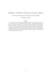
Figure 1. Reactor configuration: a fixed bed is filled with SOC<br />
and dehydrogenation catalyst. A nitrogen-diluted propane feed<br />
is fed to the bed (A). Before the break-through the bed is purged<br />
with inert nitrogen (B). The bed is regenerated with nitrogendiluted<br />
oxygen: the SOC is replenished, and the coke is burned<br />
<strong>of</strong>f (C). After purging with inert nitrogen the bed is ready for<br />
dehydrogenation again (D).<br />
mixture <strong>of</strong> a dehydrogenation catalyst and a SOC (see Figure<br />
1). During the first step, propane reacts in the following<br />
processes: homogeneous and heterogeneous dehydrogenation,<br />
eq 1, homogeneous cracking, eq 2, and homogeneous<br />
and heterogeneous hydrogenolysis, eqs 3 and 4. For the<br />
dehydrogenation reaction we selected a conventional platinumbased<br />
dehydrogenation catalyst as described by van Sint<br />
<strong>An</strong>naland et al. 25,26<br />
C 3 H 8 T C 3 H 6 + H 2 (1)<br />
C 3 H 8 f C 2 H 4 + CH 4 (2)<br />
C 3 H 8 + H 2 f C 2 H 6 + CH 4 (3)<br />
C 3 H 6 + H 2 f C 2 H 4 + CH 4 (4)<br />
The dehydrogenation catalyst suffers from the formation<br />
<strong>of</strong> coke, especially at the elevated temperatures at which the<br />
dehydrogenation reaction takes place. In our model we<br />
incorporate the coke formation from a propene precursor (eq<br />
5). We will assume that the coke consists <strong>of</strong> carbon only.<br />
C 3 H 6 f 3C + 3H 2 (5)<br />
To prevent the hydrogen from reacting back with propene,<br />
the hydrogen is converted to water at a SOC, eq 6. In our<br />
simulations we consider an idealized SOC 20 which is<br />
assumed to oxidise hydrogen instantaneously with 100%<br />
selectivity.<br />
2CeO 2 + H 2 f Ce 2 O 3 + H 2 O (6)<br />
After a certain time on-stream the SOC becomes depleted,<br />
and the activity <strong>of</strong> the dehydrogenation catalyst is hampered<br />
by coke formation. The reactor is then purged with nitrogen<br />
to prevent the formation <strong>of</strong> flammable or explosive mixtures.<br />
In the second step the reactor is reoxidized with a 99:1 v/v<br />
N 2 :O 2 mixture. The dehydrogenation catalyst is burned clean<br />
from coke, and the SOC is replenished. In the simulations<br />
398 • Vol. 9, No. 4, 2005 / Organic Process Research & Development
Table 1. Input parameters and variables used in the<br />
calculations <strong>of</strong> the two-step oxidative dehydrogenation<br />
symbol name value unit<br />
∆H reaction enthalpy variable J mol -1<br />
ɛ void fraction <strong>of</strong> the bed 0.69 -<br />
λ cat effective packed bed 0.50 J K -1 m -1 s -1<br />
heat conductivity<br />
µ ij reaction coefficient - -<br />
homogeneous reaction<br />
ν ij reaction coefficient - -<br />
heterogeneous reaction<br />
F molar density variable mol m -3<br />
F cat mass density <strong>of</strong> SOC/ 4 × 10 3 kg m -3<br />
dehydrogenation catalyst<br />
a external surface area 2500 m 2 m -3<br />
C p,cat heat capacity catalyst 1160 J K -1 kg -1<br />
C p,gas heat capacity gas variable J K -1 mol -1<br />
D ax axial dispersion coefficient 10 -5 m 2 s -1<br />
F molar flow variable mol m -2 s -1<br />
h f heat transfer coefficient 200 J K -1 m -2 s -1<br />
k l mass transfer coefficient 10 -3 ms -1<br />
L reactor length 5 m<br />
R i reaction rate <strong>of</strong> reaction i variable mol m -2 s -1<br />
S BET catalyst surface area 1.53 × 10 4 m 2 kg -1<br />
t time coordinate variable s<br />
T temperature <strong>of</strong> the variable K<br />
gas phase<br />
T s temperature <strong>of</strong> the variable K<br />
solid phase<br />
x reactor length coordinate variable m<br />
Y i gas fraction component i variable -<br />
Y i,S gas fraction component i<br />
at surface<br />
variable -<br />
we assume that both the reoxidation <strong>of</strong> the SOC as well as<br />
the combustion <strong>of</strong> carbon are instantaneous reactions and<br />
that coke is removed from the carrier during the oxidation<br />
step. After a second purge with nitrogen the reactor is ready<br />
for a new cycle.<br />
The Process Model. To study the feasibility <strong>of</strong> the<br />
process described in the previous section, we calculated<br />
process variables such as conversion, selectivity, heat formation,<br />
and yields using the gPROMS program (gPROMS,<br />
version 2.1.1., PSE Enterprise Ltd., London). In our model,<br />
we incorporated the reactions described above and studied<br />
the reactor performance for a SOC with an endothermic<br />
reduction by hydrogen. The reactor consists <strong>of</strong> a onedimensional<br />
bed filled with a catalyst phase comprising the<br />
two different uniformly dispersed active sites: dehydrogenation<br />
catalyst sites and solid oxygen carrier sites. The<br />
catalyst is treated as a pseudohomogeneous impermeable<br />
phase <strong>of</strong> constant voidage and density. The gas is introduced<br />
at one end <strong>of</strong> the reactor and moves in plug flow with<br />
superimposed axial dispersion over the bed. We follow Reid 19<br />
to describe the physical properties <strong>of</strong> the gas phase using<br />
data for the pure components. The pressure drop over the<br />
bed and the radial dispersion in concentration and temperature<br />
are assumed to be negligible. Diffusion limitation in<br />
the catalyst particles is neglected. The diffusional mass<br />
balance <strong>of</strong> this reactor is described by eq 7. The symbols<br />
used in the equations are explained in Table 1.<br />
∂(FY i ) ∂(FY i )<br />
ɛ )- + ɛ ∂ ∂Y i<br />
∂t ∂x ∂x( FD ax<br />
∂x) + N i,SOC + N i,DHC +<br />
ɛ ∑ µ i,k R k (7)<br />
k<br />
Equation 7 describes the time development <strong>of</strong> the mass<br />
fluxes, FY i , <strong>of</strong> the components i in the reactor as a result <strong>of</strong><br />
convection, axial dispersion, chemical reactions in the gas<br />
phase, and exchange with the catalyst phase. The mass fluxes<br />
toward the SOC and dehydrogenation catalyst reaction sites<br />
are denoted by N i,SOC and N i,DHC , respectively. The concentration<br />
<strong>of</strong> the components at the catalyst surface depends on<br />
the type <strong>of</strong> the site; the dehydrogenation site is a source for<br />
hydrogen, whereas the SOC site is a sink (see Figure 2).<br />
The molar flux, N i , <strong>of</strong> component i is thus a sum <strong>of</strong> the<br />
convection <strong>of</strong> component i from or to the surface and the<br />
mass transfer due to concentration differences <strong>of</strong> the gas at<br />
the solid and in the bulk, eq 8.<br />
N i ) ∑<br />
j<br />
ν i,j R j ) k l aF(Y i,S - Y i ) + Y i,S∑N i (8)<br />
i<br />
The mass transfer coefficient <strong>of</strong> the components, k l , from<br />
the solid to the gas phase is assumed to be constant, with<br />
zero accumulation <strong>of</strong> components on the catalyst phase.<br />
Danckwerts-type boundary conditions are applied at the<br />
boundaries <strong>of</strong> the bed.<br />
The heat balance <strong>of</strong> the reactor is captured in eqs 9 and<br />
10. Equation 9 describes the temperature evolution in the<br />
reactor in the gas phase,<br />
∂T<br />
ɛFC p,gas<br />
∂t )-FC ∂T<br />
p,gas<br />
∂x ∂x( + ɛ<br />
∂ λ ∂T<br />
gas<br />
∂x) + ah f (T s - T) +<br />
ɛ ∑ ∑µ i,k R k ∆H R (9)<br />
i k<br />
and eq 10 describes the development <strong>of</strong> temperature in the<br />
solid phase.<br />
∂T s<br />
(1 - ɛ)F cat C p,cat<br />
∂t ) ah f (T - T s<br />
∂x( ) + (1 - ɛ)<br />
∂ ∂T s<br />
λ cat )<br />
∂x +<br />
Table 1 summarises the simulation variables and constants,<br />
together with their values and units.<br />
Simulations. We calculated the conversion <strong>of</strong> propane<br />
and determined the selectivity <strong>of</strong> the reactor towards propene<br />
by integrating the mass and heat balances (eqs 7-10) taking<br />
into account the dehydrogenation, hydrogenolysis, and cracking<br />
<strong>of</strong> propane and hydrogenolysis <strong>of</strong> propene in both the<br />
gas phase and on the dehydrogenation sites <strong>of</strong> the solid phase.<br />
For these reactions, as well as for the coke-formation process,<br />
we used the kinetics data as published by van Sint <strong>An</strong>naland<br />
et al. 25,26<br />
The integration was carried out using the gPROMS<br />
environment in the form <strong>of</strong> a second-order upwind scheme. 13<br />
The reactor was discretised based on a staggered grid using<br />
50 cells <strong>of</strong> equal volume. 17 Component fluxes and velocities<br />
were defined at the borders <strong>of</strong> the cells. Physical properties<br />
∑<br />
i<br />
∑<br />
j<br />
ν i,j R j ∆H R (10)<br />
Vol. 9, No. 4, 2005 / Organic Process Research & Development • 399
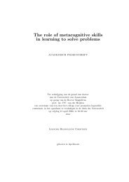
Figure 2. Schematic concentration pr<strong>of</strong>ile with dehydrogenation<br />
catalyst, gas bulk and SOC. Hydrogen (C H2 , black line) is<br />
produced on the dehydrogenation catalyst (DHC) by dehydrogenation.<br />
The catalyst surface is separated from the gas bulk<br />
by a film with thickness δ. At the surface <strong>of</strong> the SOC hydrogen<br />
is instantaneously oxidised to water. The direction <strong>of</strong> the N H2,DHC<br />
and N H2,SOC is presented by arrows (to and from the bulk <strong>of</strong><br />
the gas).<br />
such as pressure and temperature were defined at the centers<br />
<strong>of</strong> the cells. The initial bed temperature was taken to be equal<br />
to the gas inlet temperature. The latter was kept constant<br />
throughout the cycle. The process cycle started with the<br />
dehydrogenation step, lasting 600 s with a gas flow <strong>of</strong> 2<br />
mol m -2 s -1 , followed by a nitrogen purge for 100 s at a<br />
flow rate <strong>of</strong> 2 mol m -2 s -1 . For the reoxidation a mixture <strong>of</strong><br />
1% oxygen in nitrogen was used at a flow rate <strong>of</strong> 20 mol<br />
m -2 s -1 . The reoxidation time was taken to be variable to<br />
allow time for the coke, formed during the dehydrogenation,<br />
to be burned <strong>of</strong>f and the SOC to be replenished. Finally, the<br />
reactor was purged again for 100 s with a 2 mol m -2 s -1<br />
nitrogen flow.<br />
In our study the reactor length is kept constant. For each<br />
temperature and SOC content an optimal reactor length can<br />
be found, and <strong>of</strong> course the residence time in the reactor<br />
also depends on temperature. The distribution <strong>of</strong> the volume<br />
ratio <strong>of</strong> catalyst vs SOC, here taken as uniform throughout<br />
the reactor, can also influence the performance. A treatment<br />
<strong>of</strong> these effects is beyond the scope <strong>of</strong> this paper.<br />
Results and Discussion<br />
We determined the cyclic steady state for a reactor filled<br />
with a homogeneous mixture <strong>of</strong> dehydrogenation catalyst and<br />
SOC, by the procedure described above. The ratio between<br />
the SOC and dehydrogenation catalyst was varied from 0 to<br />
75% vol. <strong>of</strong> the catalyst phase. The inlet temperature<br />
(constant throughout each process cycle) was taken from T<br />
) 748KtoT ) 873 K in steps <strong>of</strong> 25 K.<br />
<strong>Propane</strong> Conversion and Selectivity. We studied the<br />
conversion <strong>of</strong> propane and determined the selectivities<br />
towards propene, coke, and hydrogenolised products (C 2 H 6 ,<br />
C 2 H 4 ,CH 4 ). The performance <strong>of</strong> the reactor is determined<br />
by a balance between competing reactions: on one hand the<br />
conversion <strong>of</strong> propane into propene, on the other hand the<br />
(hydro)cracking <strong>of</strong> propane and conversion <strong>of</strong> propene in<br />
undesirable products. For low inlet temperatures the conversion<br />
<strong>of</strong> propane to propene is low, but so are the rates <strong>of</strong> the<br />
competing reactions, leading to a high selectivity. At higher<br />
temperatures, competing reactions start to influence reactor<br />
performance by creating more by-products. Thus, the increase<br />
in conversion is accompanied by a decrease in selectivity.<br />
This is illustrated in Figure 3 by the dotted line connecting<br />
the simulations performed without SOC at various temperatures.<br />
Figure 3 also shows that removing hydrogen from<br />
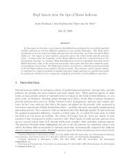
Figure 3. Selectivity towards propene versus conversion <strong>of</strong><br />
propane plot <strong>of</strong> the two-step oxidative dehydrogenation. The<br />
entrance temperature <strong>of</strong> the feed streams is varied: (9) 748<br />
K, (0) 773 K, (2) 798 K, (4) 823 K, (b) 848 K, and (O) 873 K<br />
with double steady state. The SOC content as volume fraction<br />
<strong>of</strong> the bed is varied for each temperature: 0, 1, 5, 10, 25, 50,<br />
and 75%, respectively. The 0% SOC points are connected by<br />
a dotted line. Lines are used to guide the eye.<br />
the reactor increases both conversion and selectivity. However,<br />
for a SOC concentration exceeding 10% vol. <strong>of</strong> the<br />
catalyst phase, the conversion goes down, while the selectivity<br />
approaches a plateau. The general shape <strong>of</strong> the lying<br />
U-curves can be understood as follows. Initially, both<br />
conversion and selectivity increase when more SOC is added.<br />
The conversion increases because the presence <strong>of</strong> the SOC<br />
removes hydrogen, shifting the equilibrium <strong>of</strong> the dehydrogenation<br />
reaction <strong>of</strong> propane to the product side. The<br />
selectivity increases because the removal <strong>of</strong> hydrogen from<br />
the reactor prevents hydrogenolysis reactions from taking<br />
place. However, when SOC concentration reaches 10% vol.<br />
<strong>of</strong> the catalyst phase, conversion starts to decrease when the<br />
SOC concentration is increased further, while the rise in<br />
selectivity is only marginal at best. At this point the<br />
diminishing amount <strong>of</strong> dehydrogenation catalyst is no longer<br />
compensated by the shift in equilibrium in favor <strong>of</strong> the<br />
dehydrogenation products. The selectivity no longer increases<br />
because most <strong>of</strong> hydrogen is already oxidized by the SOC.<br />
This pattern holds for temperatures up to 798 K. Addition<br />
<strong>of</strong> more than 10% SOC increases the selectivity, but the<br />
conversion drops.<br />
At T ) 823 K we see a similar pattern for lower SOC<br />
concentrations: Adding a small amount <strong>of</strong> SOC increases<br />
conversion and selectivity. The pattern changes when the<br />
reactor is filled with 75% vol. SOC. Now selectivity and<br />
conversion increase compared to those at 50% vol. SOC.<br />
This pattern is repeated at higher temperatures (T ) 848 and<br />
873 K) and can be explained by a combination <strong>of</strong> the<br />
following factors. First, at higher temperatures the equilibrium<br />
<strong>of</strong> the dehydrogenation reaction shifts towards the<br />
product side, and the reaction rate <strong>of</strong> the dehydrogenation<br />
reaction increases, thus <strong>of</strong>fsetting the drop in conversion due<br />
to fewer dehydrogenation sites at higher SOC concentrations<br />
and lower temperatures. Second, the hydrogen reduction at<br />
the SOC is nearly complete at high temperatures, leaving<br />
less hydrogen available for hydrogenolysis, thus increasing<br />
selectivity.<br />
400 • Vol. 9, No. 4, 2005 / Organic Process Research & Development
Figure 4. Temperature pr<strong>of</strong>ile <strong>of</strong> the double cyclic steady state for a reactor filled with a catalyst mixture comprising volume<br />
fractions <strong>of</strong> 10% SOC and 90% dehydrogenation catalyst. The inlet temperature <strong>of</strong> the gas is 873 K in all four consecutive reaction<br />
steps.<br />
At feed temperatures up to 848 K the reactor has one<br />
steady state. Increasing the gas inlet temperature to T ) 873<br />
K leads to a double steady state (represented in Figure 3 by<br />
two series <strong>of</strong> points at T ) 873 K). The double steady state<br />
occurs when the reactor is uniformly filled with a mixture<br />
<strong>of</strong> SOC and dehydrogenation catalyst (Figure 4). When the<br />
reactor is filled with just the dehydrogenation catalyst (SOC<br />
concentration 0%), no double steady state is observed. The<br />
doubling <strong>of</strong> the steady state is caused by large temperature<br />
swings in the reactor. The first cycle starts with a nearly<br />
uniform bed temperature, the temperature <strong>of</strong> the feed in the<br />
oxidation step. Because <strong>of</strong> the high inlet temperature, a<br />
considerable amount <strong>of</strong> coke is deposited on the bed during<br />
the dehydrogenation step. The combustion <strong>of</strong> this coke in<br />
the reoxidation phase generates a considerable temperature<br />
rise. At the start <strong>of</strong> a new cycle, the bed temperature is still<br />
high due to the coke burn-<strong>of</strong>f in the previous reoxidation,<br />
and large amounts <strong>of</strong> coke are formed. These large amounts<br />
<strong>of</strong> coke require increasingly long oxidation times. Since the<br />
SOC reoxidation and coke burn <strong>of</strong>f are considered instantaneous,<br />
a sharp reaction front travels through the reactor.<br />
Regenerated parts <strong>of</strong> the bed have now time to be cooled by<br />
the oxidative flow; when all coke is removed and the SOC<br />
is replenished in the second cycle, the bed temperature is<br />
nearly uniform again.<br />
Hydrogen Conversion and Selectivity. Hydrogen is<br />
produced by dehydrogenation and during coke formation. It<br />
is consumed by reduction <strong>of</strong> the SOC or by hydrogenolysis.<br />
Even when no SOC is present, hydrogen will be chemically<br />
removed by hydrogenolysis. However, hydrogenolysis can<br />
destroy the reactant, propane, and the product, propene.<br />
Therefore, oxidation <strong>of</strong> hydrogen can improve propene<br />
selectivity by quenching hydrogenolysis. Figure 5 shows the<br />
selectivity towards hydrogen oxidation versus the total<br />
hydrogen consumption. <strong>An</strong> increase in the SOC concentration<br />
in the reactor increases both the conversion <strong>of</strong> hydrogen and<br />
its selectivity towards water at all temperatures by opening<br />
up a reaction path to the oxidation <strong>of</strong> hydrogen to form water.<br />
Adding even a small fraction SOC to the reactor filled with<br />
only dehydrogenation catalyst increases the hydrogen conversion<br />
significantly (see Figure 6). This supports the<br />
phenomena we described before: the addition <strong>of</strong> only 10%<br />
vol. SOC boosts hydrogen conversion to levels higher than<br />
90%. However, an even more efficient hydrogen removal<br />
has to compete with the loss <strong>of</strong> a large amount <strong>of</strong> dehydrogenation<br />
sites.<br />
The reaction rates for the two hydrogen conversion routes<br />
are different. Hydrogen is oxidized instantaneously on the<br />
SOC, whereas the hydrogenolysis can be described by an<br />
Arrhenius-type relation. Figure 6 shows that the hydrogen<br />
conversion decreases with increasing temperature. This seems<br />
contradictory, since the hydrogen removal rate increases<br />
concomitant with temperature. At the same time, however,<br />
hydrogen production also increases. The increase is due to<br />
Vol. 9, No. 4, 2005 / Organic Process Research & Development • 401
Figure 5. Selectivity towards water (instead <strong>of</strong> towards<br />
hydrogenolysis products) versus conversion (ratio between the<br />
reacted and formed hydrogen) plot <strong>of</strong> the hydrogen consumption.<br />
The entrance temperature <strong>of</strong> the feed streams is varied:<br />
(9) 748 K, (0) 773 K, (2) 798 K, (4) 823 K, (b) 848 K, and (O)<br />
873 K with double steady state. For each temperature the points<br />
indicate the SOC content as volume fraction <strong>of</strong> the bed: 0, 1,<br />
5, 10, 25, 50, and 75%, respectively. Lines are used to guide<br />
the eye.<br />
Figure 6. Hydrogen conversion versus SOC content in the<br />
fixed bed. The entrance temperature <strong>of</strong> the feed streams is<br />
varied: (9) 748 K, (0) 773 K, (2) 798 K, (4) 823 K, (b) 848 K,<br />
and (O) 873 K with double steady state. For each temperature<br />
the SOC content as volume fraction <strong>of</strong> the bed is varied: 0, 1,<br />
5, 10, 25, 50, and 75%, respectively. Lines are used to guide<br />
the eye.<br />
the shift in reaction equilibrium <strong>of</strong> propane dehydrogenation<br />
towards the product side and to a strong increase in coke<br />
formation (with associated hydrogen production). Thus,<br />
although more hydrogen is removed, even more is formed<br />
at high temperatures, explaining the overall lower hydrogen<br />
conversion.<br />
Propene Productivity vs Selectivity. Coke combustion<br />
and reoxidation <strong>of</strong> the SOC both require large amounts <strong>of</strong><br />
oxygen. This leads to long reoxidation times, especially for<br />
high inlet temperatures. The total cycle time can lengthen<br />
to up to 75 times the time required for the dehydrogenation<br />
step. This means that high conversions do not automatically<br />
lead to high production rates (defined as propene yield<br />
divided by cycle time). Figure 7 shows the selectivities versus<br />
production rate. At a first glance, the results seem contrary<br />
to those presented in Figure 3sthe highest production rates<br />
are obtained at the lowest inlet temperatures. However, at<br />
Figure 7. Selectivity versus yield/cycle time plot <strong>of</strong> the twostep<br />
oxidative dehydrogenation. The entrance temperature <strong>of</strong><br />
the feed streams is varied: (9) 748 K, (0) 773 K, (2) 798 K,<br />
(4) 823 K, (b) 848 K, and (O) 873 K with double steady state.<br />
The volume fraction SOC <strong>of</strong> the bed is varied for each<br />
temperature: 0, 1, 5, 10, 25, 50, and 75%, respectively. Lines<br />
are used to guide the eye.<br />
higher inlet temperatures more coke is formed, which takes<br />
more time to burn <strong>of</strong>f. Roughly 50% <strong>of</strong> the oxygen in the<br />
reoxidation step goes to coke burning instead <strong>of</strong> reoxidizing<br />
the solid oxygen carrier. This leads to longer cycle times<br />
and lower production rates.<br />
Alternative Oxidants: Pros and Cons. Reoxidation<br />
times <strong>of</strong> the two-step oxidative dehydrogenation process are<br />
extensive, especially when the reactor is operated at elevated<br />
temperatures. One option to shorten the cycle time is to<br />
increase the oxygen content <strong>of</strong> the oxidizing feed stream.<br />
However, this will destroy the platinum dispersion on the<br />
catalyst 3 and will also lead to a large temperature rise in the<br />
bed. A better alternative is using high concentrations <strong>of</strong><br />
milder oxidants, for example CO 2 or H 2 O to replenish the<br />
SOC. If these mild oxidants would not be sufficient to burn<br />
<strong>of</strong> the coke, a further oxidation step with oxygen can be<br />
applied after the mild reoxidation step. Because the SOC is<br />
already replenished, significantly less time will be required<br />
for this oxidation step.<br />
H 2 O is an interesting alternative oxidant because <strong>of</strong> the<br />
hydrogen produced in its reduction. Now the reactor would<br />
function as a separator: The hydrogen produced in the<br />
dehydrogenation reaction is released in the reoxidation step<br />
when H 2 O is reduced. Since the reaction with hydrogen is<br />
assumed to be instantaneous, oxygen vacancies will concentrate<br />
near the exit <strong>of</strong> the reactor when water is used as<br />
oxidant. Only then water can reoxidize the SOC, and the<br />
produced hydrogen has a chance to escape the reactor without<br />
being reoxidized. When the reduction proceeds at a lower<br />
pace than the reoxidation, this process option becomes even<br />
more feasible. A drawback for the use <strong>of</strong> water as oxidant<br />
is that the hydrogen production in the reoxidation is<br />
endothermic, and thus the energy gained in hydrogen<br />
oxidation is lost.<br />
Conclusions<br />
Our results show that the addition <strong>of</strong> a SOC effectively<br />
removes hydrogen produced in the dehydrogenation <strong>of</strong><br />
propane. This shifts the equilibrium <strong>of</strong> the dehydrogenation<br />
402 • Vol. 9, No. 4, 2005 / Organic Process Research & Development
eaction towards the product, propene. Furthermore, that if<br />
the SOC is increased to above 10% vol. <strong>of</strong> the catalyst phase,<br />
the benefit <strong>of</strong> shifting the equilibrium to the propene side<br />
by removing hydrogen is overturned by the decrease in<br />
conversion due to the diminishing amount <strong>of</strong> dehydrogenation<br />
catalyst. Addition <strong>of</strong> a SOC in the dehydrogenation <strong>of</strong><br />
propane increases selectivity and conversion to the desired<br />
propene.<br />
At high temperatures, formation <strong>of</strong> coke increases the<br />
cycle time <strong>of</strong> the reactor significantly due to the longer<br />
regeneration times. This negatively affects the production<br />
<strong>of</strong> propene by wasting valuable reactor time in the cokeburning<br />
process. As a solution to the long cycle times, we<br />
suggest the use <strong>of</strong> milder oxidants, such as water, in the<br />
reoxidation step. Further studies <strong>of</strong> the use <strong>of</strong> alternative,<br />
milder oxidants to reduce cycle times and to recover<br />
hydrogen may suggest ways to further enhance the efficiency<br />
and potential <strong>of</strong> the two-step catalytic dehydrogenation<br />
process and will be carried out in our laboratory.<br />
Acknowledgment<br />
E.A.G. gratefully acknowledges financial support from<br />
NWO-Chemische Wetenschappen. We thank Process System<br />
Enterprise Ltd. for help with implementation <strong>of</strong> the model<br />
in gPROMS and Dr. M. van Sint <strong>An</strong>naland for discussions<br />
and comments.<br />
Received for review February 15, 2005.<br />
OP050020R<br />
Vol. 9, No. 4, 2005 / Organic Process Research & Development • 403