Audio/Video Receiver - Radio Shack
Audio/Video Receiver - Radio Shack
Audio/Video Receiver - Radio Shack

You also want an ePaper? Increase the reach of your titles
YUMPU automatically turns print PDFs into web optimized ePapers that Google loves.
STANDBY<br />
POWER<br />
DSP<br />
SPEAKER<br />
PHONES<br />
STAV-3770 AUDIO/VIDEO RECEIVER<br />
MEMORY FM MONO CLASS<br />
STATION<br />
TUNING<br />
SELECT<br />
4X100WATT<br />
EQUAL POWER OUTPUT<br />
OSR<br />
VCR<br />
TAPE 1<br />
DVD/LD<br />
CD<br />
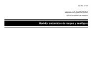
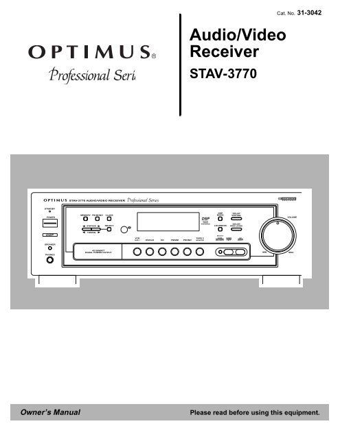
<strong>Audio</strong>/<strong>Video</strong><br />
<strong>Receiver</strong><br />
STAV-3770<br />
Cat. No. 31-3042<br />
Owner’s Manual Please read before using this equipment.<br />
FM/AM<br />
PHONO<br />
TAPE 2<br />
MONITOR<br />
DSP<br />
DIGITAL<br />
SIGNAL<br />
PROCESSOR<br />
DSP<br />
MODE<br />
LOUDNESS<br />
DOLBY<br />
VIRTUAL<br />
DOLBY<br />
PRO LOGIC<br />
SELECT<br />
TONE DOWN UP<br />
BALANCE LEFT RIGHT<br />
DOLBY SURROUND<br />
PRO LOGIC<br />
VOLUME<br />
MIN MAX
2<br />
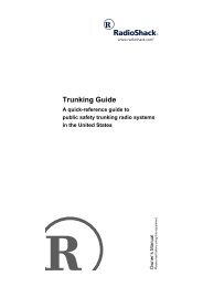
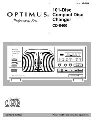
Introducing the Optimus STAV-3770<br />
Your Optimus STAV-3770 <strong>Audio</strong>/<strong>Video</strong> <strong>Receiver</strong> is the perfect control center for<br />
your audio/video system. It combines 100 watts-per-channel of clean power<br />
with modern styling. And, it provides connections for one tape deck, one audio/<br />
video source, one more tape deck or audio/video playback source, a turntable,<br />
a CD player, and a video monitor.<br />
Your receiver also has special sound options. Dolby Pro Logic‘ Surround Sound<br />
delivers movie theater sound for audio/video programs (especially those<br />
encoded with Dolby Surround Sound signals). Dolby 3CH Logic provides a<br />
wider sound field than ordinary playback. DSP Effects creates a listening environment<br />
that simulates a concert hall, jazz club, theater, or a dance hall. Dolby<br />
Virtual provides a three-dimensional sound field using only the front left and<br />
right speakers.<br />
Additional features include:<br />
Digital-Synthesized Tuner Precisely tunes to AM and FM stations.<br />
30 Memory Locations Let you store and recall the frequencies for up to 30 AM/FM stations.<br />
Automatic Tuning Searches for the next available AM/FM station.<br />
Tape Monitoring Lets you listen to the actual recording as you record, if your tape deck has a<br />
tape-monitoring feature.<br />
Built-In Protection Circuits Automatically turn off the receiver to help avoid power surges or short circuit<br />
damage.<br />
Remote Control Lets you use a single remote control for the receiver and other compatible components<br />
connected to the receiver.<br />
Note: The remote control requires two AA batteries (not supplied).<br />
We recommend you record the receiver’s serial number here. The number is on the receiver’s<br />
back panel.<br />
Serial Number:_____________________________________________<br />
Note to the Cable TV System Installer:<br />
This reminder is provided to call the CATV system installer’s attention to Article 820-40 of the National Electrical Code that<br />
provides guidelines for proper grounding and, in particular, specifies that the cable ground shall be connected to the grounding<br />
system of the building as close to the point of cable entry as practical.<br />
Manufactured under license from Dolby Laboratories Licensing Corporation.<br />
Dolby, Pro Logic, and the double-D symbol ( ) are trademarks of Dolby Laboratories Licensing Corporation.<br />
© 1998 Tandy Corporation.<br />
All Rights Reserved.<br />
<strong>Radio</strong><strong>Shack</strong> and Optimus are registered trademarks used by Tandy Corporation.
This receiver is made and tested to meet exacting<br />
safety standards. It meets both UL and FCC requirements<br />
WARNING: TO REDUCE THE RISK OF<br />
FIRE OR ELECTRIC SHOCK, DO NOT<br />
EXPOSE THIS APPLIANCE TO RAIN OR<br />
MOISTURE.<br />
CAUTION<br />
RISK OF ELECTRIC SHOCK.<br />
DO NOT OPEN.<br />
CAUTION: TO REDUCE THE RISK OF<br />
ELECTRIC SHOCK, DO NOT REMOVE<br />
COVER OR BACK. NO USER-SERVICE-<br />
ABLE PARTS INSIDE. REFER SERVICING<br />
TO QUALIFIED PERSONNEL.<br />
!<br />
IMPORTANT SAFETY INSTRUCTIONS<br />
This symbol is intended to alert you to the<br />
presence of uninsulated dangerous voltage<br />
within the system’s enclosure that might be of<br />
sufficient magnitude to constitute a risk of<br />
electric shock. Do not open the system’s<br />
case.<br />
This symbol is intended to inform you that important<br />
operating and maintenance instructions<br />
are included in the literature<br />
accompanying this system.<br />
CAUTION<br />
Power Lines—Locate an outdoor antenna away from<br />
power lines.<br />
Nonuse Periods—Unplug the receiver’s power cord<br />
when you will not use it for extended periods.<br />
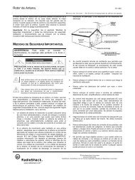
Outdoor Antenna Grounding—If an outside antenna<br />
or cable system is connected to the receiver, ground<br />
the antenna or cable system so as to provide some<br />
protection against voltage surges and built-up static<br />
charges. Article 810 of the National Electrical Code,<br />
ANSI/NFPA 80, provides information about proper<br />
grounding of the mast and supporting structure,<br />
grounding of the lead-in wire to an antenna discharge<br />
unit, size of grounding conductors, location of antennadischarge<br />
unit, connection to grounding electrodes,<br />
and requirements for the grounding electrode. See the<br />
example below.<br />
Electric<br />
Service<br />
Equipment<br />
Ground Clamp<br />
NEC -- National Electrical Code<br />
Antenna<br />
Lead-In<br />
Wire<br />
!<br />
Antenna<br />
Discharge Unit<br />
(NEC Section 810-20)<br />
Grounding Conductors<br />
(NEC Section 810-21)<br />
Grounding Clamps<br />
Power Service Grounding<br />
Electrode System<br />
(NEC Article 250, Part H)<br />
Careful attention is devoted to quality standards in the manufacture of your receiver, and safety is<br />
a major factor in its design. However, safety is also your responsibility.<br />
This section lists important information that will help you properly use and enjoy your receiver and<br />
accessories. Read all the included safety and operating instructions before using your receiver. Follow<br />
them closely, and retain them for future reference.<br />
Heed Warnings — Follow all warnings on the product and in the operating instructions.<br />
Cleaning — Unplug this product from the wall outlet before cleaning. Use only a damp cloth for<br />
cleaning. Do not use liquid or aerosol cleaners.<br />
Attachments — Do not use attachments/accessories not recommended by the product manufacturer,<br />
as they might create a hazard.<br />
Water and Moisture — Do not use this product near water (for example, near a bathtub, washbowl,<br />
kitchen sink, or laundry tub; in a wet basement; or near a swimming pool).<br />
Accessories — Do not place this product on an unstable cart, stand, tripod, bracket, or table. The<br />
product may fall, causing serious injury to a child or adult, and serious damage to the product. Use<br />
only with a cart, stand, tripod, bracket, or table recommended by the manufacturer or sold with the<br />
product. Follow the manufacturer's instructions for mounting, and use a recommended mounting<br />
accessory.<br />
Carts — Move the product on a cart carefully. Quick stops, excessive force, and<br />
uneven surfaces may cause the product/cart to overturn.<br />
Ventilation — Slots and openings in the cabinet provide ventilation, ensure reliable<br />
operation, and protect from overheating. Do not block or cover these openings,<br />
and do not place the product on a bed, sofa, rug, or other similar surface. Do<br />
not place the product in a built-in bookcase or rack unless it provides proper ventilation<br />
as specified by the manufacturer.<br />
Power Sources — Operate this product using only the power source indicated on its marking label.<br />
If you are not sure of your home's power type, consult your product dealer or local power company.<br />
Polarization — This product is equipped with a polarized AC line plug (a plug having one blade<br />
wider than the other). This plug will fit in the power outlet only one way. This is a safety feature. If<br />
you cannot insert the plug fully into the outlet, try reversing the plug. If the plug still doesn't fit, contact<br />
your electrician to replace your obsolete outlet. Do not defeat the safety purpose of the polarized<br />
plug. If you need an extension, use a polarized cord.<br />
Power-Cord Protection — Route power-supply cords so they are not likely to be walked on or<br />
pinched by items placed on or against them, paying particular attention to cords at plugs, convenience<br />
receptacles, and the point where they exit from the product.<br />
Lightning — For added protection for this product during a lightning storm, or when it is left unattended<br />
and unused for long periods of time, unplug it from the wall outlet and disconnect the antenna<br />
or cable system. This will prevent damage to the product due to lightning and power-line surges.<br />
Overloading — Do not overload wall outlets, extension cords, or integral convenience receptacles,<br />
as this can result in a risk of fire or electric shock.<br />
Objects and Liquids — Never push objects of any kind into this product through openings, as they<br />
may touch dangerous voltage points or short out parts that could result in a fire or electric shock.<br />
Never spill liquid of any kind on the product.<br />
Servicing — Do not attempt to service this product yourself, as opening or removing covers may<br />
expose you to dangerous voltage or other hazards. Refer all servicing to qualified service personnel.<br />
Damage Requiring Service — Unplug this product from the wall outlet and refer servicing to qualified<br />
service personnel under the following conditions:<br />
• When the power-supply cord or plug is damaged.<br />
• If liquid has been spilled or objects have fallen into the product.<br />
• If the product has been exposed to rain or water.<br />
• If the product does not operate normally by following the operating instructions. Adjust only<br />
those controls that are covered by the operating instructions, as an improper adjustment of<br />
other controls may result in damage and will often require extensive work by a qualified technician<br />
to restore the product to normal operation.<br />
• If the product has been dropped or damaged in any way.<br />
• When the product exhibits a distinct change in performance.<br />
Replacement Parts — When replacement parts are required, be sure the service technician uses<br />
replacement parts specified by the manufacturer or having the same characteristics as the original<br />
part. Unauthorized substitutions may result in fire, electric shock, or other hazards.<br />
Safety Check — Upon completion of service or repairs to this product, ask the service technician<br />
to perform safety checks to determine that the product is in proper operating condition.<br />
Wall or Ceiling Mount — The product should be mounted to a wall or ceiling only as recommended<br />
by the manufacturer.<br />
Heat — The product should be situated away from heat sources such as radiators, heat registers,<br />
stoves, or other products (including amplifiers) that produce heat.<br />
3
4<br />
Contents<br />
Preparing Your <strong>Receiver</strong> . . . . . . . . . . . . . . . . . . . . . . . . . . . . . . . . . . . . . . . . . . . . . . . . . . . . . . . . . . . . . . . . . . . . . . . . . . . . . .5<br />
Positioning Speakers . . . . . . . . . . . . . . . . . . . . . . . . . . . . . . . . . . . . . . . . . . . . . . . . . . . . . . . . . . . . . . . . . . . . . . . . . . .5<br />
Connecting Speakers . . . . . . . . . . . . . . . . . . . . . . . . . . . . . . . . . . . . . . . . . . . . . . . . . . . . . . . . . . . . . . . . . . . . . . . . . . .6<br />
Connecting Program Sources . . . . . . . . . . . . . . . . . . . . . . . . . . . . . . . . . . . . . . . . . . . . . . . . . . . . . . . . . . . . . . . . . . . . .9<br />
Connecting the Antennas . . . . . . . . . . . . . . . . . . . . . . . . . . . . . . . . . . . . . . . . . . . . . . . . . . . . . . . . . . . . . . . . . . . . . . . 11<br />
Using One Remote Control for More than One Unit . . . . . . . . . . . . . . . . . . . . . . . . . . . . . . . . . . . . . . . . . . . . . . . . . . .13<br />
Installing the Remote Control’s Batteries . . . . . . . . . . . . . . . . . . . . . . . . . . . . . . . . . . . . . . . . . . . . . . . . . . . . . . . . . . .13<br />
Using the AC Power Outlet . . . . . . . . . . . . . . . . . . . . . . . . . . . . . . . . . . . . . . . . . . . . . . . . . . . . . . . . . . . . . . . . . . . . . .14<br />
Connecting to AC Power . . . . . . . . . . . . . . . . . . . . . . . . . . . . . . . . . . . . . . . . . . . . . . . . . . . . . . . . . . . . . . . . . . . . . . . .14<br />
Basic Operation . . . . . . . . . . . . . . . . . . . . . . . . . . . . . . . . . . . . . . . . . . . . . . . . . . . . . . . . . . . . . . . . . . . . . . . . . . . . . . . . . . . .15<br />
Tuning the <strong>Radio</strong> . . . . . . . . . . . . . . . . . . . . . . . . . . . . . . . . . . . . . . . . . . . . . . . . . . . . . . . . . . . . . . . . . . . . . . . . . . . . . .16<br />
Using FM MONO . . . . . . . . . . . . . . . . . . . . . . . . . . . . . . . . . . . . . . . . . . . . . . . . . . . . . . . . . . . . . . . . . . . . . . . . . . . . .17<br />
Adjusting Balance . . . . . . . . . . . . . . . . . . . . . . . . . . . . . . . . . . . . . . . . . . . . . . . . . . . . . . . . . . . . . . . . . . . . . . . . . . . . .17<br />
Using Headphones . . . . . . . . . . . . . . . . . . . . . . . . . . . . . . . . . . . . . . . . . . . . . . . . . . . . . . . . . . . . . . . . . . . . . . . . . . . .18<br />
Muting the <strong>Receiver</strong> . . . . . . . . . . . . . . . . . . . . . . . . . . . . . . . . . . . . . . . . . . . . . . . . . . . . . . . . . . . . . . . . . . . . . . . . . . .18<br />
Loudness Control . . . . . . . . . . . . . . . . . . . . . . . . . . . . . . . . . . . . . . . . . . . . . . . . . . . . . . . . . . . . . . . . . . . . . . . . . . . . .18<br />
Bypassing the Sound Controls . . . . . . . . . . . . . . . . . . . . . . . . . . . . . . . . . . . . . . . . . . . . . . . . . . . . . . . . . . . . . . . . . . .18<br />
Cassette Deck/VCR Features . . . . . . . . . . . . . . . . . . . . . . . . . . . . . . . . . . . . . . . . . . . . . . . . . . . . . . . . . . . . . . . . . . . . . . . . .19<br />
Using the VCR/TAPE 1 and TAPE 2 MONITOR Buttons . . . . . . . . . . . . . . . . . . . . . . . . . . . . . . . . . . . . . . . . . . . . . . .19<br />
Monitoring a Program Source . . . . . . . . . . . . . . . . . . . . . . . . . . . . . . . . . . . . . . . . . . . . . . . . . . . . . . . . . . . . . . . . . . . .19<br />
Dubbing a Cassette Tape . . . . . . . . . . . . . . . . . . . . . . . . . . . . . . . . . . . . . . . . . . . . . . . . . . . . . . . . . . . . . . . . . . . . . . .19<br />
Playing and Recording <strong>Video</strong> Tapes . . . . . . . . . . . . . . . . . . . . . . . . . . . . . . . . . . . . . . . . . . . . . . . . . . . . . . . . . . . . . . .20<br />
Using Advanced Sound Options . . . . . . . . . . . . . . . . . . . . . . . . . . . . . . . . . . . . . . . . . . . . . . . . . . . . . . . . . . . . . . . . . . . . . .21<br />
Sound Mode Adjustments . . . . . . . . . . . . . . . . . . . . . . . . . . . . . . . . . . . . . . . . . . . . . . . . . . . . . . . . . . . . . . . . . . . . . . .22<br />
Listening Position for the Dolby Virtual Mode . . . . . . . . . . . . . . . . . . . . . . . . . . . . . . . . . . . . . . . . . . . . . . . . . . . . . . . .23<br />
Using the Remote Control . . . . . . . . . . . . . . . . . . . . . . . . . . . . . . . . . . . . . . . . . . . . . . . . . . . . . . . . . . . . . . . . . . . . . . . . . . . .24<br />
Troubleshooting . . . . . . . . . . . . . . . . . . . . . . . . . . . . . . . . . . . . . . . . . . . . . . . . . . . . . . . . . . . . . . . . . . . . . . . . . . . . . . . . . . . .26<br />
Care and Maintenance . . . . . . . . . . . . . . . . . . . . . . . . . . . . . . . . . . . . . . . . . . . . . . . . . . . . . . . . . . . . . . . . . . . . . . . . . . . . . . .27<br />
The FCC Wants You to Know . . . . . . . . . . . . . . . . . . . . . . . . . . . . . . . . . . . . . . . . . . . . . . . . . . . . . . . . . . . . . . . . . . . . . . . . .28<br />
Specifications . . . . . . . . . . . . . . . . . . . . . . . . . . . . . . . . . . . . . . . . . . . . . . . . . . . . . . . . . . . . . . . . . . . . . . . . . . . . . . . . . . . . . .29<br />
Index to Features by Control Name . . . . . . . . . . . . . . . . . . . . . . . . . . . . . . . . . . . . . . . . . . . . . . . . . . . . . . . . . . . . . . . . . . . .31
Preparing Your <strong>Receiver</strong><br />
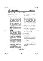
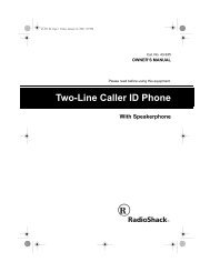
Positioning Speakers<br />
a<br />
L R<br />
b<br />
b<br />
Caution: Make all the necessary connections before you plug in or turn on the receiver.<br />
a=b<br />
a = b<br />
Person Normal in Listening Point Area<br />
Halfway Point<br />
Between Midway Point Speake<br />
Between Speakers<br />
• Surround speakers generally sound<br />
best if you position them above ear<br />
level.<br />
• To avoid interference with the picture<br />
on a nearby TV, use magnetically<br />
shielded speaker systems. This is particularly<br />
important for the center<br />
speaker since it is usually located<br />
closest to the TV.<br />
Where you place your speakers (not supplied) can make a noticeable difference<br />
in your system’s sound. The guidelines in this section will help you choose the<br />
best locations. After you use your receiver for a while, you might want to try different<br />
locations for your speakers.<br />
Bass response depends largely on speaker location. For strong bass, place the<br />
speakers in the corners of the room. If you want even stronger bass, place the<br />
speakers directly on the floor. If the bass is too strong, move the speakers<br />
slightly away from the corners of the room, or raise them 6 to 18 inches off the<br />
floor. You can buy speaker stands at your local <strong>Radio</strong><strong>Shack</strong> store.<br />
The distance between the speakers should be about the same as the distance<br />
between the normal listening point and the point halfway between the speakers.<br />
If you place the speakers too close together, you reduce the stereo separation.<br />
If you place them too far apart, you reduce the bass effect and create a hole in<br />
the middle of the sound.<br />
Most speakers have a tweeter dispersion angle of about 60 degrees. Ideally,<br />
your listening position should be just inside the overlap area of the tweeter dispersion.<br />
You can angle the speakers toward you for better stereo effect.<br />
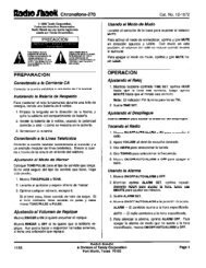
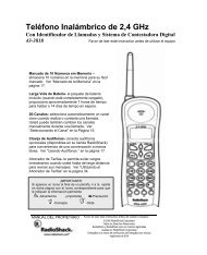
To position your speakers for surround sound, place the front speakers at the<br />
front of your listening area, and place the (rear) surround speakers behind or to<br />
the sides of the listening point (see “Using Advanced Sound Options” on<br />
Page 21). Also, place the center speaker above, below, or behind the TV.<br />
Sound might not appear to coincide with the picture if you place it beside the TV.<br />
Front Left<br />
Speaker<br />
Rear Left<br />
Speaker<br />
TV<br />
Center Speaker<br />
Front<br />
Listening<br />
Area<br />
Rear<br />
Rear Right<br />
Speaker<br />
Front Right<br />
Speaker<br />
5
6<br />
Preparing Your <strong>Receiver</strong><br />
Connecting Speakers Preparing the Speaker Wires<br />
Follow these guidelines when you select<br />
and connect speakers.<br />
• Only connect speakers that are rated<br />
at between 8 and 16 Ohms.<br />
• Be sure you properly connect all<br />
speakers.<br />
• Do not connect two pairs of speakers<br />
to a single set of terminals at the<br />
same time.<br />
• Realistic, Optimus, and other highquality<br />
speakers have color-coded<br />
speaker terminals (red for positive polarity<br />
and black for negative polarity).<br />
Use these color-coded terminals as a<br />
guide to help you properly connect the<br />
speakers to the receiver.<br />
• Use 16-gauge (or larger) speaker wire<br />
for all speaker connections, and consider<br />
possible speaker locations before<br />
you decide how much speaker<br />
wire you need.<br />
Speaker wire consists of two conductors (individual wires) encased in insulation<br />
and is usually color-coded or marked with a ridge along one side so you can<br />
identify each conductor. Use these markings as a guide to help you properly<br />
connect the speakers to your receiver.<br />
Follow these steps to prepare the speaker wires.<br />
Conductor<br />
Speaker Wire<br />
Conductor<br />
Conductor<br />
1. Cut the speaker wires to the necessary length.<br />
2. Separate the wires about 4 inches on each end.<br />
Wire Strands Strand<br />
Wire Wire Strands Strands<br />
3. Using a wire stripper, carefully strip about 3 /4 inch of insulation from the<br />
end of each conductor.<br />
4. Twist the end of each conductor to secure any loose wire strands.
Note: Be sure you connect the receiver’s<br />
right and left positive (+) and<br />
negative (–) terminals to the speaker’s<br />
corresponding right and left positive (+)<br />
and negative (–) terminals.<br />
AUDIO<br />
IN<br />
Amplified<br />
Subwoofer<br />
Connecting the Front Speakers<br />
Preparing Your <strong>Receiver</strong><br />
Right Front Speakers Left<br />
Center Speaker<br />
SUB<br />
WOOFER<br />
PRE<br />
OUT<br />
FRONT SPEAKERS<br />
Follow these steps to connect the right speaker to the receiver’s right FRONT<br />
SPEAKERS terminals.<br />
1. Press open the receiver’s FRONT SPEAKERS R (+) red lever and insert the<br />
ridged or color-coded conductor’s end into the small hole. Press the lever<br />
closed to secure the conductor.<br />
2. Press open the receiver’s FRONT SPEAKERS R (–) black lever and insert the<br />
other conductor’s end into the small hole. Press the lever closed to<br />
secure the conductor.<br />
3. Connect the ridged or color-coded conductor’s loose end to the right<br />
speaker’s positive (+) terminal.<br />
R<br />
CENTER<br />
SPEAKER<br />
Right Surround Speakers Left<br />
4. Connect the remaining loose conductor to the right speaker’s negative (–)<br />
terminal.<br />
Repeat Steps 1–4 to connect the left speaker to the receiver’s FRONT SPEAKERS<br />
left terminals.<br />
L<br />
R<br />
R<br />
L<br />
L<br />
CAUTION: SPEAKER IMPEDANCE<br />
8 ~ 16 / SPEAKER<br />
SURROUND<br />
SPEAKERS<br />
7
8<br />
Preparing Your <strong>Receiver</strong><br />
Connecting Surround-Sound Speakers<br />
You can connect a pair of speakers to the receiver for surround-sound programs.<br />
Follow the steps in “Connecting the Front Speakers” to connect the<br />
speakers to the SURROUND SPEAKERS terminals.<br />
Connecting the Center Speaker<br />
The center speaker gives additional ambience to surround sound. Follow the<br />
steps in “Connecting the Front Speakers” to connect the center speaker to the<br />
CENTER SPEAKER terminals.<br />
Connecting a Subwoofer Amplifier<br />
Your receiver includes a line-level subwoofer output. Connecting a subwoofer to<br />
your system dramatically extends bass response for incredible richness and<br />
depth. When you listen to surround-sound programs, a subwoofer enhances<br />
your home theater experience by realistically re-creating the rumble of an earthquake,<br />
the bone-jarring percussion of a cannon, and more. To use the subwoofer<br />
output, simply connect SUBWOOFER PRE OUT to an amplified subwoofer’s<br />
line-level input or to an amplifier to which you have connected a subwoofer.<br />
<strong>Radio</strong><strong>Shack</strong> stores sell a variety of suitable subwoofers and amplifiers.
Connecting<br />
Program Sources<br />
Note: Use shielded audio cables with<br />
phono connectors for all audio connections.<br />
Note: If you place the cassette deck directly<br />
above, below, or to the left of the<br />
receiver, the receiver could interfere with<br />
the cassette deck’s operation. If possible,<br />
position the cassette deck to the<br />
right or away from the receiver.<br />
Preparing Your <strong>Receiver</strong><br />
You can connect up to five external program sources to your receiver.<br />
SIGNAL GND<br />
Connecting a Turntable<br />
Connect a turntable with a magnetic cartridge only. Some older turntables use a<br />
ceramic-type cartridge that does not work with this system.<br />
Connect the turntable’s left and right cables to the receiver’s L (left) and R (right)<br />
PHONO IN jacks. Then connect the turntable’s ground wire to the receiver’s SIG-<br />
NAL GND terminal.<br />
Connecting a CD Player<br />
To connect a CD player to the receiver, connect the CD player’s left and right<br />
output jacks to the receiver’s L and R CD IN jacks.<br />
Connecting Cassette Decks<br />
L<br />
R<br />
L<br />
R<br />
IN OUT IN OUT<br />
IN PLAY REC IN IN PLAY REC<br />
PHONO TAPE2<br />
MONITOR<br />
R<br />
L<br />
LINE<br />
REC PLAY<br />
L<br />
R<br />
REC PLAY<br />
INPUT OUTPUT<br />
CONTROL<br />
CD DVD/<br />
LD<br />
VCR/<br />
TAPE1<br />
You can connect cassette decks to the VCR/TAPE 1 and TAPE 2 MONITOR jacks.<br />
Connect the cassette deck’s output jacks to the VCR/TAPE 1 IN PLAY or TAPE 2<br />
MONITOR IN PLAY jacks, and connect the cassette deck’s input jacks to the VCR/<br />
TAPE 1 OUT REC or TAPE 2 MONITOR OUT REC jacks.<br />
You can connect a third cassette deck (for playback only) to the DVD/LD IN<br />
(audio) jacks.<br />
OUT<br />
VIDEO<br />
OUT<br />
VIDEO<br />
IN<br />
TO MONITOR TV<br />
VIDEO<br />
OUT<br />
SUB<br />
WOOFER<br />
VIDEO<br />
IN<br />
OUT PUT<br />
PRE<br />
OUT<br />
Turntable Cassette Deck CD Player<br />
L<br />
L<br />
R<br />
R<br />
R<br />
L<br />
R<br />
L<br />
R<br />
L<br />
L<br />
R<br />
CD<br />
L<br />
R<br />
9
10<br />
Preparing Your <strong>Receiver</strong><br />
Note: If your VCR is monaural, use a Yadapter<br />
(available at your local <strong>Radio</strong><strong>Shack</strong><br />
store) to connect the VCR’s<br />
audio output to both the L and R audio inputs<br />
on the receiver.<br />
L<br />
R<br />
SIGNAL GND<br />
IN OUT IN OUT<br />
IN PLAY REC IN IN PLAY REC<br />
PHONO TAPE2<br />
MONITOR<br />
CD DVD/<br />
LD<br />
Connecting <strong>Video</strong> Sources<br />
If you connect two video sources, such as VCRs, laser disc (LD) players, or digital<br />
video disc (DVD) players to your receiver, you can use the receiver to select<br />
each video source. You can also use the receiver to easily record from these<br />
video sources to the source connected to VCR/TAPE 1.<br />
Connect phono cables from each video source’s audio outputs to the receiver’s<br />
VCR/TAPE 1 IN PLAY or DVD/LD IN jacks. Then connect phono cables from the<br />
receiver’s VCR/TAPE 1 OUT REC jacks to the source’s audio input jacks.<br />
Connect video cables from each video source’s video outputs to the receiver’s<br />
VCR/TAPE 1 or DVD/LD VIDEO IN jacks. Then connect video cables from the<br />
receiver’s VCR/TAPE 1 VIDEO OUT jack to the source’s video input.<br />
Connecting a <strong>Video</strong> Monitor<br />
V<br />
VIDEO<br />
IN<br />
v<br />
CONTROL<br />
R<br />
R<br />
OUT<br />
L<br />
AUDIO<br />
OUT<br />
L<br />
L<br />
R<br />
VIDEO<br />
OUT<br />
VIDEO<br />
IN<br />
V<br />
V<br />
VIDEO<br />
OUT<br />
TO MONITOR TV<br />
VCR/<br />
TAPE1<br />
The monitor (or TV with baseband video input) you connect to the VIDEO OUT terminal<br />
can monitor any program you connect to the receiver’s VCR/TAPE 1 IN PLAY<br />
or DVD/LD IN jacks. Connect a video cable from the receiver’s VIDEO OUT TO MONI-<br />
TOR TV jack to the monitor’s video input.<br />
VIDEO<br />
OUT<br />
VIDEO<br />
IN<br />
L<br />
R<br />
SUB<br />
WOOFER<br />
PRE<br />
OUT<br />
L<br />
R<br />
AUDIO VIDEO<br />
REC PLAY<br />
L<br />
R<br />
REC PLAY<br />
INPUT OUTPUT<br />
TV Monitor DVD/LD Player VCR<br />
R<br />
L<br />
L<br />
R<br />
R<br />
VCR<br />
OUT<br />
IN<br />
L<br />
V<br />
V<br />
V<br />
V
Connecting the Antennas<br />
AM Loop<br />
Antenna<br />
Outdoor AM Antenna<br />
AM Loop<br />
Antenna<br />
LOOP<br />
ANTENNA<br />
Note: For the best results, use 75-ohm<br />
coaxial cable to connect an outdoor antenna<br />
to the receiver.<br />
LOOP<br />
ANTENNA<br />
AM<br />
FM<br />
UNBAL<br />
75<br />
LOOP<br />
ANTENNA<br />
AM<br />
FM<br />
UNBAL<br />
75<br />
ANTENN<br />
AM<br />
ANTENN<br />
FM<br />
UNBAL<br />
75<br />
ANTENN<br />
Preparing Your <strong>Receiver</strong><br />
In many areas, the supplied indoor AM loop and FM antennas provide satisfactory<br />
reception.<br />
AM Antennas<br />
Assemble the supplied AM antenna’s base by swinging the base in the direction<br />
of the arrow and inserting the antenna’s bottom tabs into the base’s slot. If the<br />
receiver is in a rack or on a shelf and there is no room for the AM loop antenna,<br />
use two screws (not supplied) to mount the base on the wall or another location<br />
as shown.<br />
Attach the antenna wires to the AM LOOP ANTENNA and (ground) terminals<br />
(upper two terminals).<br />
Place the antenna on a flat surface and rotate it for the best AM reception.<br />
Notes:<br />
• Keep the AM loop antenna connected even when you use another indoor<br />
antenna or an outdoor AM antenna.<br />
• Ensure that the antenna does not touch the receiver or any other metal<br />
object.<br />
• Do not place the antenna near a CD player, a personal computer, or a TV<br />
set.<br />
• If the wire between your AM loop antenna and receiver is too short, you<br />
can add extra wire, available at your local <strong>Radio</strong><strong>Shack</strong> store.<br />
You can also use a <strong>Radio</strong><strong>Shack</strong> shortwave antenna kit (Cat. No. 278-758),<br />
which makes an excellent outdoor AM antenna. Connect the outdoor AM<br />
antenna wire to the receiver’s AM terminal, as shown.<br />
FM Antennas<br />
Connect the supplied FM antenna to the FM UNBAL 75Ω terminal as shown, then<br />
extend it.<br />
For better FM reception, you can also use a rabbit-ear TV antenna (for indoor<br />
use only). To connect the TV antenna to the receiver, you need a VHF/UHF/FM<br />
splitter (not included). <strong>Radio</strong><strong>Shack</strong> stores carry a full line of quality antennas<br />
and antenna connection accessories.<br />
11
12<br />
Preparing Your <strong>Receiver</strong><br />
Warning: To prevent injury, read and follow<br />
all cautions and warnings that accompany<br />
the outdoor antenna.<br />
Caution: The cable’s shielding should<br />
only touch the terminal.<br />
For the best radio reception, use an outdoor antenna. Follow these steps to<br />
connect an outdoor FM antenna to the receiver using 75Ω coaxial cable.<br />
Note: If your antenna has 300Ω twin-lead cable, consult your local <strong>Radio</strong><strong>Shack</strong><br />
store for the correct adapter.<br />
1. Disconnect the supplied FM antenna from the receiver’s FM UNBAL 75Ω<br />
terminal.<br />
2. With a stripping tool, remove about 1 1 /2 inches of the outdoor antenna<br />
cable’s outer insulation to expose the cable’s shielding.<br />
3. Fold back the shielding from the inner insulation.<br />
4. Remove about 1 inch of the inner insulation from around the center wire.<br />
Outer Insulation<br />
Inner Insulation<br />
5. Pull the shielding to one side. Connect the center wire to the receiver’s FM<br />
UNBAL 75Ω terminal. Twist the shielding to secure any loose wire strands,<br />
and connect it to the FM UNBAL 75Ω terminal.<br />
Outdoor FM Antenna<br />
Shielding<br />
Shielding<br />
Center<br />
Wire<br />
Center Wire<br />
LOOP<br />
ANTENNA<br />
Note: Grounding is not necessary for reception, but we recommend it for better<br />
FM reception and to avoid damage from lightning when you use an outdoor FM<br />
antenna. Use a separate piece of thick polyvinyl insulated wire to connect the<br />
terminal to the building’s power service grounding electrode system.<br />
Warning: Never connect a wire to a gas pipe for grounding since sparks might<br />
ignite the gas.<br />
AM<br />
FM<br />
UNBAL<br />
75<br />
ANTENN
Using One Remote Control<br />
for More than One Unit<br />
Note: When you plug the cable into a<br />
component’s CONTROL IN jack, that component’s<br />
remote sensor does not function.<br />
CONTROL<br />
OUT<br />
<strong>Receiver</strong><br />
Remote<br />
Control<br />
CONTROL<br />
Installing the<br />
Remote Control’s Batteries<br />
Cautions:<br />
• Use only fresh batteries of the required<br />
size and recommended type.<br />
• Always remove old or weak batteries.<br />
Batteries can leak chemicals that can<br />
damage electronic circuits.<br />
Note: If the remote’s range is reduced,<br />
replace the batteries.<br />
IN<br />
OUT<br />
Other Component<br />
with OSR Mark<br />
To the CONTROL IN Jack<br />
of Another Component<br />
Having the OSR Mark<br />
Preparing Your <strong>Receiver</strong><br />
If you also have an Optimus professional series CD player, VCR, or cassette<br />
deck with the OSR mark ( ), you can connect its CONTROL IN jack to the<br />
receiver so you can control all of your equipment with a single remote control.<br />
You can also use the other component’s remote control by pointing it at the<br />
receiver’s front panel.<br />
1. Connect each component to the receiver as shown in “Connecting Program<br />
Sources” on Page 9.<br />
Note: You must connect the audio cables between the receiver and the<br />
other audio accessory to use your receiver’s remote control to control the<br />
accessory.<br />
2. Connect the cable supplied with the CD player, VCR, or cassette deck to<br />
the receiver’s CONTROL OUT jack and the other component’s CONTROL IN<br />
jack.<br />
3. When you want to control more than one other component using the<br />
receiver’s remote control, daisy-chain the CONTROL OUT and CONTROL IN<br />
connections as shown.<br />
The remote control uses two AA batteries (not included). For the longest battery<br />
life, we recommend alkaline batteries (such as <strong>Radio</strong><strong>Shack</strong> Cat. No. 23-557).<br />
1. Press and slide open the battery compartment cover.<br />
2. Place two fresh AA batteries in the compartment as indicated by the<br />
polarity symbols (+ and –) marked in the compartment.<br />
3. Replace the battery compartment cover.<br />
13
14<br />
Preparing Your <strong>Receiver</strong><br />
Using the AC Power Outlet<br />
Caution: Do not connect appliances with<br />
high power consumption, such as a<br />
heater, iron, monitor, or TV, to this AC<br />
outlet. Doing so can cause a risk of overheating<br />
and fire, and could damage the<br />
receiver.<br />
Connecting to AC Power<br />
Warning: To prevent electric shock, do<br />
not use this polarized plug with an extension<br />
cord, receptacle, or other outlet unless<br />
you can fully insert the blades to<br />
prevent blade exposure.<br />
Your receiver has an AC power outlet that you can use to power an electronic<br />
device, such as a turntable, cassette deck, VCR, and so on. This switched outlet<br />
turns on and off with the receiver and provides a maximum of 100 Watts.<br />
B<br />
FER<br />
FRONT SPEAKERS<br />
R<br />
CENTER<br />
SPEAKER<br />
L<br />
R<br />
R<br />
L<br />
L<br />
CAUTION: SPEAKER IMPEDANCE<br />
8 ~ 16 / SPEAKER<br />
SURROUND<br />
SPEAKERS<br />
AC OUTLET<br />
AC 120V 60Hz<br />
CAUTION:<br />
DO NOT CONNECT<br />
TV SET OR MONITOR.<br />
SWITCHED<br />
100W MAX<br />
0.8A MAX<br />
Before you plug in the receiver’s power cord, double check all other connections.<br />
To power the receiver, plug the supplied power cord into a standard AC outlet.<br />
The power cord’s plug is polarized and fits only one way.<br />
FRONT SPEAKERS<br />
R<br />
CENTER<br />
SPEAKER<br />
L<br />
R<br />
R<br />
L<br />
L<br />
CAUTION: SPEAKER IMPEDANCE<br />
8 ~ 16 / SPEAKER<br />
SURROUND<br />
SPEAKERS<br />
AC OUTLET<br />
AC 120V 60Hz<br />
CAUTION:<br />
DO NOT CONNECT<br />
TV SET OR MONITOR.<br />
SWITCHED<br />
100W MAX<br />
0.8A MAX
Basic Operation<br />
Warning: To prevent possible hearing<br />
loss, turn VOLUME to MIN before you turn<br />
on the receiver or change the program<br />
sources. After you turn on the receiver or<br />
change the program source, adjust VOL-<br />
UME to a comfortable listening level.<br />
Note: If you select a source while TAPE 2<br />
MONITOR is engaged, TAPE 2 flashes<br />
five times on the display, reminding you<br />
to disengage the TAPE 2 MONITOR function.<br />
Note: To find out what a particular button<br />
or control is used for, see Page 24 (for<br />
the remote control) or Page 31 (for the<br />
front panel) to find the page where the<br />
button or control is described.<br />
The controls on the remote control work the same as the buttons on the<br />
receiver’s front panel, though some are labeled differently.<br />
Follow these steps to use the receiver.<br />
1. Press POWER to turn on the receiver’s power. It takes about 5 seconds to<br />
begin hearing sound.<br />
2. Press SPEAKER on the left front of the receiver (if necessary) so SP A<br />
appears on the upper left portion of the display.<br />
3. Select a program source.<br />
To tune to a radio station, see “Tuning the <strong>Radio</strong>” on Page 16.<br />
To listen to signals from the component connected to TAPE 2 MONITOR,<br />
press TAPE 2 MONITOR so TAPE 2 appears on the display.<br />
To listen to a source other than one connected to TAPE 2 MONITOR, be sure<br />
TAPE 2 does not show on the display. If necessary, press TAPE 2 MONITOR<br />
so TAPE 2 disappears. Then press VCR/TAPE 1, DVD/LD (digital video disc/<br />
laser disc), CD, AM/FM (tuner), or PHONO, or repeatedly press FUNC on the<br />
remote control, to display the desired program source.<br />
4. Adjust VOLUME clockwise to increase the volume or counterclockwise to<br />
decrease it. Or, you can use MASTER VOLUME –/+ on the remote control.<br />
5. Adjust the bass, treble, or balance to suit your listening preference.<br />
Repeatedly press TONE/BALANCE on the front of the receiver until the item<br />
you want to adjust appears on the display — TREB., BASS, or BAL-<br />
ANCE. Then press DOWN/LEFT or UP/RIGHT until you get the desired sound.<br />
For more detail on adjusting the sound balance, see “Adjusting Balance”<br />
on Page 17.<br />
6. When you finish using the receiver, press POWER to turn it off.<br />
15
16<br />
Basic Operation<br />
Tuning the <strong>Radio</strong><br />
Note: For weak signals, we recommend<br />
manual tuning.<br />
Your receiver has four types of electronic tuning — manual, automatic, direct<br />
access, and memory.<br />
Manual and Automatic Tuning<br />
Follow these steps to manually or automatically tune to stations.<br />
Hint: If none of the tuning buttons on the remote control operate, press TUNER<br />
first.<br />
1. Press FM/AM (BAND on the remote control) to select the tuner. Then press<br />
FM/AM (BAND) again to select the desired band. The receiver tunes to and<br />
displays the frequency last selected in that band.<br />
If A, B, or C and a single digit number appear to the left of the station frequency,<br />
press SELECT (BAND on the remote control) so the band name (AM<br />
or FM) appears.<br />
2. To manually select the next lower or higher frequency, press TUNING (<br />
FREQ on the remote control) once to manually select the next lower or<br />
higher frequency. Or, hold down the button to rapidly change frequencies,<br />
and release it.<br />
To automatically search for the next lower or higher station, hold down<br />
TUNING ( FREQ on the remote control) until the display starts to<br />
change, then release it. The receiver searches down or up the band to the<br />
next strong station.<br />
Notes:<br />
• TUNED appears when you receive a strong signal.<br />
• If you press TUNING at the top of the frequency range or TUNING at<br />
the bottom of the frequency range, the display returns to the other<br />
end of the range.<br />
Direct Access Tuning (Remote Control Only)<br />
Follow these steps to directly enter a frequency.<br />
1. Press FM/AM (BAND on the remote control) to select the tuner. Then press<br />
FM/AM (BAND) again to select the desired band. The receiver tunes to and<br />
displays the frequency last selected in that band.<br />
2. Press DIRECT ACCESS. _ _ __ __ __ appears on the display<br />
with the first _ _ flashing.<br />
3. Enter the desired frequency using the number buttons.<br />
Notes:<br />
• If you enter an invalid frequency (for example, entering 828), the receiver<br />
tunes to the closest valid frequency (830 kHz).<br />
• If you do not press a key within 5 seconds, the receiver exits direct access<br />
tuning. Start over at Step2.
Note: A class is a group of up to 10 station<br />
frequencies.<br />
Notes:<br />
• If you store a frequency in a memory<br />
that already contains a frequency, you<br />
replace the previous frequency.<br />
• If your receiver is disconnected from<br />
AC power for several days, it loses all<br />
the stored frequencies.<br />
Using FM MONO<br />
Adjusting Balance<br />
Memory Tuning<br />
Basic Operation<br />
Memory tuning lets you store up to 30 AM or FM frequencies in three different<br />
classes (10 frequencies in each class), then quickly tune to a class and station.<br />
Follow these steps to store a station in a memory location using the front panel<br />
controls. (You cannot store a station in a memory using the remote control)<br />
1. Press FM/AM to select the tuner, then press FM/AM again to select the<br />
desired band.<br />
2. Tune to the frequency you want to store.<br />
If desired, press FM MONO for FM stereo or monaural sound (see “Using<br />
FM MONO”). This setting is also stored in memory.<br />
3. Press MEMORY. The class (A, B, or C) and __ (for the channel number)<br />
flash on the display for about 5 seconds.<br />
4. Press CLASS until the class you want (A, B, or C) appears, then press STA-<br />
TION or until the channel number you want appears.<br />
In about five seconds, the class and channel number light steadily, indicating<br />
the receiver stored the frequency.<br />
To tune to a stored station, press CLASS so the desired class number appears,<br />
then repeatedly press STATION or to select the channel. Or, you can directly<br />
enter the channel number using that number’s key on the remote control.<br />
To receive FM stations in stereo, press FM MONO so MONO disappears from the<br />
display. STEREO appears when you receive an FM broadcast in stereo.<br />
You can improve the reception of weak FM stations by pressing FM MONO until<br />
MONO appears. This reduces noise while you listen to a weak FM station, but<br />
you get monaural instead of stereo sound.<br />
The TONE/BALANCE control lets you adjust the sound balance between the left<br />
and right speakers. If you properly position the speakers and your listening area<br />
is centered between them, the center control setting is usually best (see “Positioning<br />
Speakers” on Page 5).<br />
For an unusual speaker placement, adjust the speaker balance as follows:<br />
1. Press FM/AM to select the tuner, then press FM/AM again to select the FM<br />
band.<br />
2. Press FM MONO so MONO appears. The sound is monaural instead of stereo,<br />
so each speaker delivers the same output.<br />
3. Repeatedly press TONE/BALANCE on the front of the receiver until BAL-<br />
ANCE appears. Then press DOWN/LEFT or UP/RIGHT until you hear the<br />
sound coming equally from each speaker when you are in the listening<br />
area.<br />
4. Press FM MONO so MONO disappears from the display.<br />
17
18<br />
Basic Operation<br />
Using Headphones<br />
Muting the <strong>Receiver</strong><br />
Loudness Control<br />
Bypassing the Sound<br />
Controls (Remote Control<br />
Only)<br />
To listen with headphones (not supplied), insert the headphones’ 1 /4-inch plug<br />
into the receiver’s front panel PHONES jack. To silence the speakers and listen<br />
with headphones without disturbing others, press SPEAKER so only SP<br />
appears on the display.<br />
Listening Safely<br />
To protect your hearing, note the following when using headphones.<br />
• Set the volume to its lowest setting before you begin listening. After you<br />
begin listening, adjust the volume to a comfortable level.<br />
• Do not listen at extremely high volume levels. Extended highvolume<br />
listening can lead to permanent hearing loss.<br />
• Once you set the volume, do not increase it. Over time, your ears adapt to<br />
the volume level, so a volume level that does not cause discomfort might<br />
still damage your hearing.<br />
To temporarily mute the sound, press MUTING on the remote control. --MUT-<br />
ING -- appears. Press MUTING again to restore the audio level.<br />
To increase the high and low ranges of sounds for improved audio at a low listening<br />
level, press LOUDNESS (or LOUD on the remote control) so LOUDNESS<br />
appears. Press LOUDNESS (or LOUD) again to turn off this feature.<br />
To bypass your receiver’s sound controls (BASS, TREBLE, BALANCE, or any special<br />
sound options) so you can hear the audio at its original tonal quality (for<br />
example), press DIRECT on the remote control so DIRECT appears. Press<br />
DIRECT again to turn off this feature.<br />
Note: When you turn off the bypass feature, you will have to reselect any<br />
desired special sound options (see “Using Advanced Sound Options” on<br />
Page 21).
Cassette Deck/VCR Features<br />
Using the VCR/TAPE 1 and<br />
TAPE 2 MONITOR Buttons<br />
Monitoring a<br />
Program Source<br />
Dubbing a Cassette Tape<br />
You can connect two cassette decks to the receiver. Selecting either VCR/TAPE 1<br />
or TAPE 2 MONITOR lets you hear the playback from the cassette deck you connected<br />
to the receiver’s corresponding (VCR/TAPE 1or TAPE 2 MONITOR) jacks.<br />
Press VCR/TAPE 1. VCR appears on the display. You hear the playback from the<br />
cassette deck or VCR you connected to the receiver’s VCR/TAPE 1 IN jacks.<br />
Press TAPE 2 MONITOR. TAPE 2 appears on the display along with the last program<br />
source you selected. You can hear playback or monitor a recording from<br />
the cassette deck you connected to the receiver’s TAPE 2 MONITOR jacks. The<br />
TAPE 2 MONITOR REC jacks continue to output sound from the previously selected<br />
source after you press TAPE 2 MONITOR.<br />
To return to the previous source, press TAPE 2 MONITOR again so TAPE 2 disappears.<br />
Notes:<br />
• If you press TAPE 2 MONITOR when that cassette deck is neither playing nor<br />
recording, the receiver mutes the current audio source. To hear the audio<br />
source, press TAPE 2 MONITOR so TAPE 2 disappears from the display.<br />
• Do not press TAPE 2 MONITOR while you are recording on the deck connected<br />
to TAPE 2 MONITOR REC. If you do, the recording is interrupted for<br />
about 1 second.<br />
The receiver sends the audio of the program source you select— VCR/TAPE 1,<br />
DVD/LD, CD, FM/AM (tuner), or PHONO—to the VCR/TAPE 1 OUT/REC (audio) and<br />
TAPE 2 MONITOR OUT/REC jacks. If you select VCR/TAPE 1 or DVD/LD, the video program<br />
is also sent to the VIDEO OUT TO MONITOR TV jack.<br />
The VOLUME control does not affect the level of the signal going to the tape<br />
decks.<br />
You can copy (dub) a cassette tape from one cassette deck to another through<br />
the STAV-3770.<br />
You can use either deck as the playback or recording deck. However, if you<br />
want to monitor the cassette deck during dubbing, use the deck connected to<br />
the VCR/TAPE 1 jacks as the source, and the deck you connected to the TAPE 2<br />
REC jacks as the recording deck. Then press TAPE 2 MONITOR so TAPE 2 and the<br />
last program source you selected appear on the display. See “Using the VCR/<br />
TAPE 1 and TAPE 2 MONITOR Buttons.”<br />
The VOLUME control does not affect the level of the signal going to the tape<br />
decks.<br />
19
20<br />
Cassette Deck/VCR Features<br />
Playing and Recording<br />
<strong>Video</strong> Tapes<br />
You can connect two video sources to the receiver. If you connect a VCR to the<br />
VCR/TAPE 1 and DVD/LD audio and video jacks, you can copy video cassette<br />
tapes from one VCR to another and monitor the dubbing process.<br />
Playing a <strong>Video</strong> Tape<br />
To play a video tape, load the tape into the VCR connected to either VCR/TAPE 1<br />
or DVD/LD. Press the button (VCR/TAPE 1 or DVD/LD) that corresponds to the jack<br />
the VCR is connected to. VCR or DVD/LD appears on the display. Follow the<br />
VCR’s instructions to begin playback. If you connected a monitor to the<br />
receiver’s TO MONITOR TV jack, you can view the program on that monitor.<br />
Copying a <strong>Video</strong> Tape<br />
Follow these steps to copy a video tape from one VCR to another through the<br />
STAV-3770.<br />
1. Load the tape you want to copy into the VCR connected to DVD/LD.<br />
2. Load a blank tape (or one you want to record over) into the VCR connected<br />
to the VCR/TAPE 1 jacks.<br />
3. Press DVD/LD.<br />
4. Begin recording and playback on the VCRs.<br />
Important: Most material performed in public, such as concerts, plays, and<br />
movies, or distributed on prerecorded video tapes is copyrighted. The unauthorized<br />
recording or duplication of copyrighted material is a violation of the copyright<br />
laws of most countries and such duplication may result in fines,<br />
imprisonment, or both. Note, however, that in the United States, it is not a violation<br />
of U.S. copyright laws for a consumer to record a broadcast television program<br />
for private (in-home) viewing.
Using Advanced Sound Options<br />
Your receiver has four special sound options: Dolby Pro Logic Surround, Dolby<br />
3CH Logic, DSP Effect, and Dolby Virtual. These special options enhance the<br />
sound from a connected program source.<br />
Notes:<br />
• To get the full benefit from programs encoded with Dolby Surround<br />
Sound, you need a stereo VCR or DVD/LD player.<br />
• Dolby Surround does not operate correctly if the signal passes through a<br />
graphic equalizer. If you connected an equalizer to the TAPE 2 MONITOR<br />
jacks, do not select TAPE 2 MONITOR when you listen to Dolby Surround<br />
signals.<br />
To turn on Dolby Pro Logic Surround or Dolby 3CH Logic, press PRO LOGIC on<br />
the remote control until PRO LOGIC, THEATER 1, or THEATER 2 appears on<br />
the display, then press SURROUND followed by CENTER MODE to select NORMAL,<br />
WIDE, PHANTOM, or 3chLOGIC. See “Sound Mode Adjustments (Remote<br />
Control Only)” on Page 22 for information about each of these options.<br />
For Dolby Virtual, press DOLBY VIRTUAL (VIRTUAL on the remote control) to turn<br />
this feature on or off. To turn on a DSP effect, press DSP MODE until the desired<br />
option (see below) appears on the display.<br />
Dolby Pro Logic Surround<br />
Dolby Pro Logic Surround puts you in the middle of the action. The center- and<br />
rear-channel speakers add incredible realism by directing the sound to the<br />
appropriate speakers, making you feel like you are really there. Pro Logic is<br />
the standard.<br />
Dolby 3CH Logic<br />
Dolby 3CH Logic produces a more spacious sound field than is possible with<br />
ordinary stereo playback by sending the rear channel’s sound to the front left<br />
and right speakers. Select 3chLOGIC when you play a Dolby Surround Sound<br />
program and do not have rear speakers.<br />
Dolby Virtual<br />
Dolby Virtual lets you enjoy programs encoded with Dolby Surround while using<br />
only two front speakers.<br />
DSP Effect<br />
You can choose one of five DSP effects — HALL, JAZZ, DANCE, THEATER 1,<br />
or THEATER 2. Hall simulates a large concert hall, best suited for classical music.<br />
Jazz provides the acoustic effects generally heard in jazz clubs. Dance<br />
gives the effect of a discotheque. Both theater modes provide the effect of a<br />
movie theater. THEATER 1 sounds like a large movie theater. THEATER 2<br />
seems like a smaller theater. Try each setting to find the best effect for your programs.<br />
21
22<br />
Using Advanced Sound Options<br />
Sound Mode Adjustments<br />
(Remote Control Only)<br />
Note: If you do not use a center speaker,<br />
the monaural signals are only reproduced<br />
if you select PHANTOM.<br />
Note: Use the VOLUME control to adjust<br />
the overall sound level.<br />
Center Mode Setting<br />
The center mode setting affects the center channel’s bass signals. It operates<br />
only when you select the Dolby Pro Logic Surround or Dolby 3CH Logic mode.<br />
On the remote control, press SURROUND then CENTER MODE. Each time you<br />
press CENTER MODE, the setting changes: NORMAL, WIDE, PHANTOM, or<br />
3chLOGIC.<br />
NORMAL — For a small center speaker. The front left and right speakers play<br />
the center-channel bass sounds.<br />
WIDE — For a medium or large center speaker. The center speaker plays the<br />
center-channel bass sounds.<br />
PHANTOM — For no center speaker. All center-channel sound comes from the<br />
front left and right speakers.<br />
3chLOGIC — For no rear speakers. The rear channel’s sound is sent to the<br />
front left and right speakers.<br />
Test Tone<br />
The test tone lets you balance the signal levels between all your speakers. To<br />
adjust the levels, see “Center Level” and “Rear Level.”<br />
To turn on the test tone, select one of the surround sound modes (PRO LOGIC,<br />
THEATER 1, THEATER 2, or 3chLOGIC) then press SURROUND. Then press<br />
TEST TONE. The receiver sounds a 2-second tone from the front left, center, front<br />
right, and surround (rear) speakers, in sequence. Lch, Cch, Rch, and Sch<br />
appear as the test tone sounds.<br />
The center test tone sounds and Cch appears only when you select Normal,<br />
Wide, or 3CH Logic.<br />
If you select 3CH Logic, the receiver sounds the 2-second tone from the left,<br />
center, and right speakers, in sequence.<br />
Press TEST TONE again to turn off this feature.<br />
Center Level<br />
Press – CENTER LEVEL + to adjust the center speaker sound level.<br />
Rear Level<br />
Press – REAR LEVEL + to adjust the rear speakers’ sound level.
Notes:<br />
• For Dolby Pro Logic Surround, the delay<br />
is preset to 5 ms.<br />
• The delay time does not affect the<br />
DSP or Dolby Virtual mode.<br />
Delay Time<br />
Using Advanced Sound Options<br />
In the Dolby Pro Logic Surround modes (PRO LOGIC, THEATER 1, and THE-<br />
ATER 2), the receiver slightly delays the sound going to the rear speakers. You<br />
can change this delay time from 15 to 30 milliseconds (ms) in 5 ms steps. Adjust<br />
the delay time for the best surround effect.<br />
Press SURROUND, then hold down DELAY TIME to change the delay time. The<br />
receiver displays the selected time.<br />
Effect Level<br />
With DSP and Dolby Virtual, you can change the delay time to alter the sound<br />
effect. You can set different levels for each mode independently (from 10 to 90<br />
for DSP, and from 30 to 90 for Dolby Virtual).<br />
Press SURROUND, then hold down DISC EFFECT – or + to change the effect level.<br />
Dolby Virtual effects change considerably when the listening position changes.<br />
It sounds best when you move farther away from the speakers (about 1.2 times<br />
farther than the distance between the left and right speakers).<br />
Also, the effect can vary depending on the source program.<br />
23
TUNER<br />
24<br />
Using the Remote Control<br />
CD<br />
TUNER<br />
RECEIVER<br />
POWER<br />
POWER<br />
TAPE BAND<br />
CENTER<br />
MODE<br />
CONTROL<br />
MODE<br />
SURROUND<br />
FM<br />
MONO<br />
VIRTUAL<br />
FUNC<br />
CLASS<br />
LOUD<br />
DIRECT<br />
FREQ<br />
DIRECT<br />
ACCESS<br />
1 2 3<br />
TEST<br />
TONE<br />
4 5 6<br />
7 8 9<br />
DELAY<br />
TIME<br />
0<br />
STATION<br />
REAR<br />
LEVEL<br />
CENTER<br />
LEVEL<br />
DISC<br />
EFFECT<br />
PRO LOGICDSP<br />
MODE MUTING<br />
MASTER<br />
VOLUME<br />
AUDIO/VIDEO<br />
SYSTEM REMOTE OSR<br />
RECEIVER POWER<br />
<strong>Receiver</strong>/<br />
Amplifier<br />
Buttons<br />
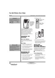
The remote control works up to a distance of about 23 feet, and within a 30degree<br />
angle on either side of the receiver. Point the control at the receiver’s<br />
front panel and press the desired button(s).<br />
Many buttons on the remote control work the same as buttons on the receiver’s<br />
front panel. Use these buttons exactly as you would use the corresponding buttons<br />
on the receiver.<br />
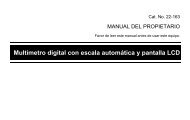
CONTROL MODE Buttons<br />
The three CONTROL MODE buttons select the device you connected to the CON-<br />
TROL OUT jack of the STAV-3770, CD player, VCR, or cassette deck.<br />
<strong>Receiver</strong>/Amplifier Operation<br />
Before operation, press TUNER to select receiver/amplifier operation.<br />
STATION Tunes to the next higher or lower memory location.<br />
BAND Selects the AM or FM tuner band.<br />
FREQ Tunes to radio stations.<br />
FM MONO Selects the FM reception mode.<br />
CLASS Selects the memory class.<br />
DIRECT ACCESS Allows direct input of the station frequency.<br />
Number Buttons Select the corresponding memory station. During Direct Access,<br />
enter the station’s frequency.<br />
TEST TONE Sounds test tones from each speaker when pressed after SUR-<br />
ROUND.<br />
– REAR LEVEL + Controls the sound level of the rear speakers when pressed after<br />
SURROUND.<br />
CENTER MODE Selects among the three center modes or 3CH Logic when<br />
pressed after SURROUND.<br />
– CENTER LEVEL + Controls the sound level of the center speaker when pressed after<br />
SURROUND.<br />
DELAY TIME Sets the rear-channel delay for Dolby Pro Logic Surround and<br />
Simulated Surround programs when pressed after SURROUND.<br />
– EFFECT+ Adjusts the level of DSP or Dolby Virtual mode.<br />
PRO LOGIC Selects Dolby Pro Logic Surround.<br />
DSP MODE Selects the DSP mode; HALL, JAZZ, DANCE, THEATER 1, or<br />
THEATER 2.<br />
MUTING Silences the receiver. Press again to restore the sound to its previous<br />
level.<br />
VIRTUAL Selects Dolby Virtual.<br />
LOUD Turns the loudness feature on and off.<br />
FUNC Selects a program source (VCR, PHONO, tuner, CD, or DVD/<br />
LD). Repeatedly press until the display shows the desired program<br />
source.
CD<br />
TAPE<br />
CD<br />
TUNER<br />
RECEIVER<br />
POWER<br />
POWER<br />
TAPE BAND<br />
CENTER<br />
MODE<br />
CONTROL<br />
MODE<br />
SURROUND<br />
CD<br />
TUNER<br />
RECEIVER<br />
POWER<br />
FM<br />
MONO<br />
VIRTUAL<br />
FUNC<br />
CLASS<br />
LOUD<br />
DIRECT<br />
FREQ<br />
AUDIO/VIDEO<br />
SYSTEM REMOTE OSR<br />
DIRECT<br />
ACCESS<br />
1 2 3<br />
TEST<br />
TONE<br />
4 5 6<br />
7 8 9<br />
DELAY<br />
TIME<br />
0<br />
CENTER<br />
LEVEL<br />
DISC<br />
EFFECT<br />
PRO LOGICDSP<br />
MODE MUTING<br />
POWER<br />
TAPE BAND<br />
CENTER<br />
MODE<br />
CONTROL<br />
MODE<br />
SURROUND<br />
FM<br />
MONO<br />
VIRTUAL<br />
FUNC<br />
CLASS<br />
LOUD<br />
DIRECT<br />
STATION<br />
REAR<br />
LEVEL<br />
FREQ<br />
AUDIO/VIDEO<br />
SYSTEM REMOTE OSR<br />
MASTER<br />
VOLUME<br />
DIRECT<br />
ACCESS<br />
1 2 3<br />
TEST<br />
TONE<br />
4 5 6<br />
7 8 9<br />
DELAY<br />
TIME<br />
0<br />
STATION<br />
REAR<br />
LEVEL<br />
CENTER<br />
LEVEL<br />
DISC<br />
EFFECT<br />
PRO LOGICDSP<br />
MODE MUTING<br />
MASTER<br />
VOLUME<br />
CD Player<br />
Buttons<br />
Cassette<br />
Deck<br />
Buttons<br />
Using the Remote Control<br />
DIRECT Bypasses the receiver’s audio control circuits. Press again to restore<br />
the previous settings.<br />
+ MASTER VOLUME – Adjusts the system’s volume.<br />
RECEIVER POWER Turns the receiver on and off.<br />
CD Player Operation<br />
Note: You must have connected the CD player to both of your receiver’s CON-<br />
TROL OUT and audio jacks for these functions to work.<br />
Before operation, press CD to select CD player operation.<br />
POWER Turns the CD player on and off (only for CD players that have the<br />
CONTROL IN/OUT feature).<br />
| / | Returns to the beginning of the current track or advances to the<br />
next track.<br />
/ Rapidly advances backward/forward within a track.<br />
Press to pause play. Press again to resume.<br />
Stops playback.<br />
Plays the CD.<br />
– DISC + Selects discs in a multi-play CD changer. (DISC might not work<br />
with some CD players.)<br />
Cassette Deck Operation<br />
Note: You must have connected the cassette deck to both your receiver’s CON-<br />
TROL OUT and audio jacks for these functions to work.<br />
Before operation, press TAPE to select cassette deck operation.<br />
The remote control operates a single cassette deck and Deck 2 on a dual cassette<br />
deck. To operate Deck 1 on a dual cassette deck, use the buttons shown<br />
in parentheses.<br />
Note: These buttons do not work with all decks.<br />
POWER Turns on/off the cassette deck.<br />
(7) Press to play the other side of an auto-reverse cassette deck.<br />
(8) / (9) Quickly locates and plays the beginning of recorded material during<br />
play.<br />
Or, when the tape is stopped, rapidly searches forward or backward<br />
to locate a specific section of the tape.<br />
(0) Press to temporarily stop playback/recording. Press again to resume.<br />
(EFFECT –) Stops playback/recording.<br />
(+ EFFECT) Press to start normal playback.<br />
25
26<br />
Troubleshooting<br />
If the receiver is not working as it should, the following suggestions might help. If you follow the suggestions in this chart and<br />
the receiver still does not work properly, contact your local <strong>Radio</strong><strong>Shack</strong> store for assistance.<br />
Problem Cause Suggestion<br />
Power does not turn on. Power cord is disconnected. Plug in the power cord.<br />
The receiver does not respond<br />
to button presses.<br />
Protection circuit is activated. Unplug the power cord, then plug it in again.<br />
Static discharge has affected the receiver.<br />
Unplug the power cord, then plug it in again. (If<br />
static electricity is a problem, use the remote control<br />
as much as possible.)<br />
No sound. Incorrect connections. Check and correct the connections.<br />
No picture when you select a<br />
video source.<br />
The mute function is activated. Press MUTING.<br />
The volume is turned down. Turn up the volume.<br />
Speaker wires are disconnected. Connect the speaker wires.<br />
Speakers are turned off. Press SPEAKER so SP A appears on the display.<br />
TAPE 2 function is engaged. Press TAPE 2 so TAPE 2 clears from the display.<br />
The selected video source is not set<br />
correctly.<br />
Correct the problem with the selected video source.<br />
Incorrect connections. Check and correct the connections.<br />
High noise level. Station not correctly tuned. Adjust tuning.<br />
Automatic tuning does not stop<br />
when searching for stations.<br />
Cannot make copies of video<br />
tapes.<br />
Antenna not connected. Connect the antenna.<br />
FM antenna still coiled or is not<br />
pointing in the correct direction.<br />
AM loop antenna not pointing in the<br />
correct direction.<br />
Noise is coming from another electrical<br />
appliance.<br />
Stretch both ends of the antenna taut and reposition<br />
the antenna.<br />
Adjust the AM loop antenna.<br />
Stations are too weak. Use a better antenna.<br />
Tapes are protected by a copy protection<br />
method.<br />
Try using an AC line noise filter to reduce the noise.<br />
You cannot make a good copy.<br />
<strong>Video</strong> connections are incorrect. Check and correct the connections.<br />
Remote control does not work. Remote is set to other device. Press the CONTROL MODE button for the device to<br />
control (CD, TAPE, or TUNER).<br />
Remote does not control cassette<br />
deck or CD player.<br />
Batteries are weak. Replace the batteries.<br />
Cassette deck or CD player is not<br />
compatible.<br />
The feature only works with Optimus Professional<br />
Series components.<br />
Control cable is not plugged in. Properly connect the control cable.<br />
<strong>Audio</strong> cables are not plugged in. Properly connect the audio cables.
Care and Maintenance<br />
Your Optimus STAV-3770 <strong>Audio</strong>/<strong>Video</strong> <strong>Receiver</strong> is an example of superior design and craftsmanship. The following suggestions<br />
will help you care for the receiver so you can enjoy it for years.<br />
Keep the receiver dry. If it gets wet, wipe it dry immediately. Liquids can contain<br />
minerals that can corrode the electronic circuits.<br />
Handle the receiver gently and carefully. Dropping it can damage its circuit<br />
boards and can cause the receiver to work improperly.<br />
Use and store the receiver and its remote control only in normal temperature<br />
environments. Temperature extremes can shorten the life of electronic devices,<br />
damage batteries, and distort or melt plastic parts.<br />
Keep the receiver away from dust and dirt, which can cause premature wear of<br />
parts.<br />
Wipe the receiver with a damp cloth occasionally to keep it looking new. Do not<br />
use harsh chemicals, cleaning solvents, or strong detergents to clean the<br />
receiver.<br />
Use only fresh batteries of the recommended size and type in the remote control.<br />
Always remove old or weak batteries. They can leak chemicals that can<br />
destroy electronic circuits.<br />
Modifying or tampering with your receiver’s internal components can cause a malfunction and might invalidate the receiver’s<br />
warranty and void your FCC authorization to operate it. If the receiver is not operating as it should, take it to your local<br />
<strong>Radio</strong><strong>Shack</strong> store for assistance.<br />
27
28<br />
The FCC Wants You to Know<br />
Your receiver might cause radio or TV interference even when it is operating<br />
properly. To determine whether your receiver is causing the interference, turn off<br />
your receiver. If the interference goes away, your receiver is causing it. Try to<br />
eliminate the interference by:<br />
• Moving your radio or TV away from the receiver<br />
• Connecting your receiver to an outlet that is on a different electrical circuit<br />
from the radio or TV<br />
• Contacting your local <strong>Radio</strong><strong>Shack</strong> store for help<br />
If you cannot eliminate the interference, the FCC requires that you stop using<br />
your receiver.
Specifications<br />
Amplifier<br />
Front Channel Average Power Output . . . . . . . . . . . . . . . . . . . . . . . . . . . . . . . . . . . . . . . . 100 Watts per Channel into 8 Ohms<br />
From 40 to 20,000 Hz,<br />
With No More than 0.9% Total Harmonic Distortion<br />
Measured Pursuant to the Federal Trade Commission’s<br />
Trade Regulation Rule on Amplifier Output Power Claims<br />
Front Channel Surround Power Output . . . . . . . . . . . . . . . . . . . . . . . . . . . 100 Watts per Channel (1 kHz, 0.9% T HD, 8 Ohms)<br />
Center Channel Surround Power Output . . . . . . . . . . . . . . . . . . . . . . . . . . . . . . . . . . . . 100 Watts (1 kHz, 0.9% THD, 8 Ohms)<br />
Continuous Rear Surround Power Output . . . . . . . . . . . . . . . . . . . . . . . . . . . . . . . . . . . 100 Watts (1 kHz, 0.9% THD, 8 Ohms)<br />
Input Sensitivity/Impedance<br />
Phono . . . . . . . . . . . . . . . . . . . . . . . . . . . . . . . . . . . . . . . . . . . . . . . . . . . . . . . . . . . . . . . . . . . . . . 2.8 mV/47 kOhms<br />
CD, DVD/LD, VCR/TAPE 1, TAPE 2 Monitor . . . . . . . . . . . . . . . . . . . . . . . . . . . . . . . . . . . . . . . 200 mV/47 kOhms<br />
Phono Overload Level (0.1% THD, 1 kHz) . . . . . . . . . . . . . . . . . . . . . . . . . . . . . . . . . . . . . . . . . . . . . . . . . . . . . . . . . . . 100 mV<br />
Frequency Response<br />
Phono . . . . . . . . . . . . . . . . . . . . . . . . . . . . . . . . . . . . . . . . . . . . . . . . . . . . . . . . . . . . . . 20 Hz to 20,000 Hz ±0.3 dB<br />
CD, DVD/LD, VCR/TAPE 1, TAPE 2 Monitor . . . . . . . . . . . . . . . . . . . . . . . . . . . . . . . 5 Hz to 100,000 Hz +0/–3 dB<br />
Output Level/Impedance<br />
VCR/TAPE 1 REC, TAPE 2 Monitor REC . . . . . . . . . . . . . . . . . . . . . . . . . . . . . . . . . . . . . . . . . 200 mV/2.2 kOhms<br />
Tone Controls<br />
Bass . . . . . . . . . . . . . . . . . . . . . . . . . . . . . . . . . . . . . . . . . . . . . . . . . . . . . . . . . . . . . . . . . . . . . . . . . . . . . . . . . ±8 dB (150 Hz)<br />
Treble . . . . . . . . . . . . . . . . . . . . . . . . . . . . . . . . . . . . . . . . . . . . . . . . . . . . . . . . . . . . . . . . . . . . . . . . . . . . . . . . ±8 dB (10 kHz)<br />
Loudness . . . . . . . . . . . . . . . . . . . . . . . . . . . . . . . . . . . . . . . . . . . . . . . . . . . . . . . . . . +8 dB/+6 dB (100 Hz/10 kHz)<br />
Signal-to-Noise Ratio (IHF, Short Circuited, A Network)<br />
Phono . . . . . . . . . . . . . . . . . . . . . . . . . . . . . . . . . . . . . . . . . . . . . . . . . . . . . . . . . . . . . . . . . . . . . . . . . . . . . . . . 72 dB<br />
CD, DVD/LD, VCR/TAPE 1, TAPE 2 Monitor . . . . . . . . . . . . . . . . . . . . . . . . . . . . . . . . . . . . . . . . . . . . . . . . . . 96 dB<br />
Signal-to-Noise Ratio (EIA, at 1 Watt, 1 kHz)<br />
Phono . . . . . . . . . . . . . . . . . . . . . . . . . . . . . . . . . . . . . . . . . . . . . . . . . . . . . . . . . . . . . . . . . . . . . . . . . . . . . . . . 75 dB<br />
CD, DVD/LD, VCR/TAPE 1, TAPE 2 Monitor . . . . . . . . . . . . . . . . . . . . . . . . . . . . . . . . . . . . . . . . . . . . . . . . . . 79 dB<br />
<strong>Video</strong> Section<br />
Input Sensitivity/Impedance VCR/TAPE 1, DVD/LD . . . . . . . . . . . . . . . . . . . . . . . . . . . . . . . . . . . 1 Volt Peak-to-Peak/75 Ohms<br />
Output Level/Impedance VCR/TAPE 1 . . . . . . . . . . . . . . . . . . . . . . . . . . . . . . . . . . . . . . . . . . . . . 1 Volt Peak-to-Peak/75 Ohms<br />
Frequency Response VCR/TAPE 1, DVD/LD to Monitor . . . . . . . . . . . . . . . . . . . . . . . . . . . . . . . . . . . 5 Hz to 7 MHz +0/–3 dB<br />
Signal-to-Noise Ratio . . . . . . . . . . . . . . . . . . . . . . . . . . . . . . . . . . . . . . . . . . . . . . . . . . . . . . . . . . . . . . . . . . . . . . . . . . . . . . 55 dB<br />
Crosstalk . . . . . . . . . . . . . . . . . . . . . . . . . . . . . . . . . . . . . . . . . . . . . . . . . . . . . . . . . . . . . . . . . . . . . . . . . . . . . . . . . . . . . . . 55 dB<br />
29
30<br />
Specifications<br />
FM Tuner<br />
Frequency Range . . . . . . . . . . . . . . . . . . . . . . . . . . . . . . . . . . . . . . . . . . . . . . . . . . . . . . . . . . . . . . . . . . . . . . . 87.5 to 108 MHz<br />
Usable Sensitivity . . . . . . . . . . . . . . . . . . . . . . . . . . . . . . . . . . . . . . . . . . . . . . . . . . . . . . Mono: 13.2 dBf, IHF (1.3 μV/75 Ohms)<br />
50 dB Quieting Sensitivity<br />
Mono . . . . . . . . . . . . . . . . . . . . . . . . . . . . . . . . . . . . . . . . . . . . . . . . . . . . . . . . . . . . . . . . . . . . . . . . . . . . . . 20.2 dBf<br />
Stereo . . . . . . . . . . . . . . . . . . . . . . . . . . . . . . . . . . . . . . . . . . . . . . . . . . . . . . . . . . . . . . . . . . . . . . . . . . . . . 38.6 dBf<br />
Signal-to-Noise Ratio<br />
Mono . . . . . . . . . . . . . . . . . . . . . . . . . . . . . . . . . . . . . . . . . . . . . . . . . . . . . . . . . . . . . . . . . . . . . . . . 73 dB (at 85 dBf)<br />
Stereo . . . . . . . . . . . . . . . . . . . . . . . . . . . . . . . . . . . . . . . . . . . . . . . . . . . . . . . . . . . . . . . . . . . . . . . 70 dB (at 85 dBf)<br />
Distortion Stereo . . . . . . . . . . . . . . . . . . . . . . . . . . . . . . . . . . . . . . . . . . . . . . . . . . . . . . . . . . . . . . . . . . . . . . . . . . . 0.5% (1 kHz)<br />
Alternate Channel Selectivity . . . . . . . . . . . . . . . . . . . . . . . . . . . . . . . . . . . . . . . . . . . . . . . . . . . . . . . . . . . . . . . 60 dB (400 kHz)<br />
Stereo Separation . . . . . . . . . . . . . . . . . . . . . . . . . . . . . . . . . . . . . . . . . . . . . . . . . . . . . . . . . . . . . . . . . . . . . . . . . 40 dB (1 kHz)<br />
Frequency Response . . . . . . . . . . . . . . . . . . . . . . . . . . . . . . . . . . . . . . . . . . . . . . . . . . . . . . . . . . . . . . . 30 Hz to 15 kHz (±1 dB)<br />
Antenna Input . . . . . . . . . . . . . . . . . . . . . . . . . . . . . . . . . . . . . . . . . . . . . . . . . . . . . . . . . . . . . . . . . . . . . . . 75 Ohms Unbalanced<br />
AM Tuner<br />
Frequency Range . . . . . . . . . . . . . . . . . . . . . . . . . . . . . . . . . . . . . . . . . . . . . . . . . . . . . . . . . . . . . . . . . . . . . . . 530 to 1700 kHz<br />
Sensitivity (IHF, Loop Antenna) . . . . . . . . . . . . . . . . . . . . . . . . . . . . . . . . . . . . . . . . . . . . . . . . . . . . . . . . . . . . . . . . . . 350 μV/m<br />
Selectivity . . . . . . . . . . . . . . . . . . . . . . . . . . . . . . . . . . . . . . . . . . . . . . . . . . . . . . . . . . . . . . . . . . . . . . . . . . . . . . . . . . . . . . 25 dB<br />
Signal-to-Noise Ratio . . . . . . . . . . . . . . . . . . . . . . . . . . . . . . . . . . . . . . . . . . . . . . . . . . . . . . . . . . . . . . . . . . . . . . . . . . . . . 50 dB<br />
General<br />
Power Requirements . . . . . . . . . . . . . . . . . . . . . . . . . . . . . . . . . . . . . . . . . . . . . . . . . . . . . . . . . . . . . . . . . . 120 Volts AC, 60 Hz<br />
Power Consumption . . . . . . . . . . . . . . . . . . . . . . . . . . . . . . . . . . . . . . . . . . . . . . . . . . . . . . . . . . . . . . . . 210 Watts, 300 VA (UL)<br />
AC Outlet Ratings Switched . . . . . . . . . . . . . . . . . . . . . . . . . . . . . . . . . . . . . . . . . . . . . . . Total 100 Watts (0.8 Amps) Maximum<br />
Dimensions (HWD) . . . . . . . . . . . . . . . . . . . . . . . . . . . . . . . . . . . . . . . . . . . . . . . . . . . . . . . . . . . . . 5 5 /8 × 16 9 /16 × 12 13 /16 Inches<br />
(143 × 420 × 325 mm)<br />
Weight . . . . . . . . . . . . . . . . . . . . . . . . . . . . . . . . . . . . . . . . . . . . . . . . . . . . . . . . . . . . . . . . . . . . . . . . . . . . . . . . . . . . . 16 lb 5 oz<br />
(7.4 kg)<br />
Specifications are typical; individual units might vary. Specifications are subject to change and improvement without notice.
Index to Features by Control Name<br />
This table lists the control and indicator names found on the front of your receiver, along with the page number where the control<br />
or indicator is discussed. To find a description for the buttons on the remote control, see “Using the Remote Control” on<br />
Page 24.<br />
Control Page<br />
TONE/BALANCE 15, 17<br />
BASS 15<br />
CD 15<br />
CLASS 17<br />
DOLBY PRO LOGIC 21<br />
DOLBY VIRTUAL 21, 23<br />
DSP MODE 21<br />
DVD/LD 15<br />
FM MONO 17<br />
FM/AM 16<br />
LOUDNESS 18<br />
MEMORY 17<br />
PHONES 18<br />
PHONO 15<br />
POWER 15<br />
SELECT 15, 16<br />
SPEAKER 15, 18<br />
STATION 17<br />
TAPE 2 MONITOR 15, 19<br />
TREBLE 15<br />
TUNING 16<br />
VCR/TAPE 1 15, 19<br />
VOLUME 15<br />
31
Limited Two-Year Warranty<br />
This product is warranted by <strong>Radio</strong><strong>Shack</strong> against manufacturing defects in material and workmanship<br />
under normal use for two (2) years from the date of purchase from <strong>Radio</strong><strong>Shack</strong> companyowned<br />
stores and authorized <strong>Radio</strong><strong>Shack</strong> franchisees and dealers. EXCEPT AS PROVIDED<br />
HEREIN, <strong>Radio</strong><strong>Shack</strong> MAKES NO EXPRESS WARRANTIES AND ANY IMPLIED WARRANTIES,<br />
INCLUDING THOSE OF MERCHANTABILITY AND FITNESS FOR A PARTICULAR PURPOSE,<br />
ARE LIMITED IN DURATION TO THE DURATION OF THE WRITTEN LIMITED WARRANTIES<br />
CONTAINED HEREIN. EXCEPT AS PROVIDED HEREIN, <strong>Radio</strong><strong>Shack</strong> SHALL HAVE NO LIABIL-<br />
ITY OR RESPONSIBILITY TO CUSTOMER OR ANY OTHER PERSON OR ENTITY WITH RE-<br />
SPECT TO ANY LIABILITY, LOSS OR DAMAGE CAUSED DIRECTLY OR INDIRECTLY BY USE<br />
OR PERFORMANCE OF THE PRODUCT OR ARISING OUT OF ANY BREACH OF THIS WAR-<br />
RANTY, INCLUDING, BUT NOT LIMITED TO, ANY DAMAGES RESULTING FROM INCONVE-<br />
NIENCE, LOSS OF TIME, DATA, PROPERTY, REVENUE, OR PROFIT OR ANY INDIRECT,<br />
SPECIAL, INCIDENTAL, OR CONSEQUENTIAL DAMAGES, EVEN IF <strong>Radio</strong><strong>Shack</strong> HAS BEEN AD-<br />
VISED OF THE POSSIBILITY OF SUCH DAMAGES.<br />
Some states do not allow the limitations on how long an implied warranty lasts or the exclusion of incidental<br />
or consequential damages, so the above limitations or exclusions may not apply to you.<br />
In the event of a product defect during the warranty period, take the product and the <strong>Radio</strong><strong>Shack</strong><br />
sales receipt as proof of purchase date to any <strong>Radio</strong><strong>Shack</strong> store. <strong>Radio</strong><strong>Shack</strong> will, at its option, unless<br />
otherwise provided by law: (a) correct the defect by product repair without charge for parts and<br />
labor; (b) replace the product with one of the same or similar design; or (c) refund the purchase<br />
price. All replaced parts and products, and products on which a refund is made, become the property<br />
of <strong>Radio</strong><strong>Shack</strong>. New or reconditioned parts and products may be used in the performance of<br />
warranty service. Repaired or replaced parts and products are warranted for the remainder of the<br />
original warranty period. You will be charged for repair or replacement of the product made after the<br />
expiration of the warranty period.<br />
This warranty does not cover: (a) damage or failure caused by or attributable to acts of God, abuse,<br />
accident, misuse, improper or abnormal usage, failure to follow instructions, improper installation or<br />
maintenance, alteration, lightning or other incidence of excess voltage or current; (b) any repairs<br />
other than those provided by a <strong>Radio</strong><strong>Shack</strong> Authorized Service Facility; (c) consumables such as<br />
fuses or batteries; (d) cosmetic damage; (e) transportation, shipping or insurance costs; or (f) costs<br />
of product removal, installation, set-up service adjustment or reinstallation.<br />
This warranty gives you specific legal rights, and you may also have other rights which vary from<br />
state to state.<br />
<strong>Radio</strong><strong>Shack</strong> Customer Relations, Dept. W, 100 Throckmorton St., Suite 600, Fort Worth, TX 76102<br />
We Service What We Sell 3/97<br />
<strong>Radio</strong><strong>Shack</strong><br />
A Division of Tandy Corporation<br />
Fort Worth, Texas 76102<br />
<br />
6A8 Printed in Indonesia