CompactPCI and AdvancedTCA Systems - OpenSystems Media
CompactPCI and AdvancedTCA Systems - OpenSystems Media
CompactPCI and AdvancedTCA Systems - OpenSystems Media

Create successful ePaper yourself
Turn your PDF publications into a flip-book with our unique Google optimized e-Paper software.
S P E C I A L<br />
E M I<br />
a board power fault condition. When the<br />
board input capacitance is fully charged<br />
<strong>and</strong> no other fault exists, the power FET<br />
is driven into the Rdson state by the hot<br />
swap control to achieve a power good<br />
condition <strong>and</strong> to minimize the power loss<br />
of the FET. With the dual use of the FET,<br />
the hot swap function must dominate control<br />
under a fault condition over the filter<br />
operation, creating an interfacing design<br />
challenge.<br />
The active filter creates a high impedance<br />
to the ripple current <strong>and</strong> works by controlling<br />
the FET drain to source voltage <strong>and</strong><br />
sensing the AC current flowing through<br />
the FET via the sense resistor. The active<br />
loop modulates the resistance of the FET<br />
to effectively make the converter switching<br />
load look like a constant current to<br />
the bus. This requires bringing the FET<br />
barely out of the Rdson region because<br />
the magnitude of the ripple current is<br />
typically in the tens of milliamps, establishing<br />
a slight headroom bias voltage.<br />
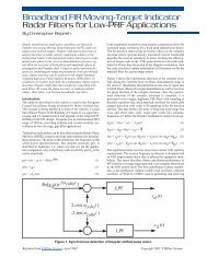
Using a wide b<strong>and</strong>width analog amplifier<br />
for U2 as shown in the schematic drawing<br />
in Figure 2, the AC ripple current can<br />
be detected across the current limit sense<br />
resistor then amplified to drive the gate<br />
of the FET. This will change the series<br />
resistance in the ohmic or triode region of<br />
the FET characteristic curve, driving the<br />
sensed AC current component on the bus<br />
to zero. The headroom voltage can be set<br />
very low by U3, depending upon the FET<br />
triode characteristics, to minimize power<br />
dissipation versus ripple current reduction<br />
or the effective attenuation of the filter. An<br />
example simulation is shown in Figure 3<br />
demonstrating the attenuation effects the<br />
active filter has on the bus ripple current<br />
versus frequency. The appropriate component<br />
parasitic elements were included<br />
in the simulation.<br />
An inductor can be considered as the<br />
sense element for both functions, with<br />
a DC resistance component equal to the<br />
sense resistor needed for the hot swap<br />
current limit level. This provides some<br />
design advantages as well as challenges.<br />
From a noise reduction st<strong>and</strong>point the<br />
inductor will provide additional passive<br />
attenuation in combination with the<br />
converter input capacitors, adding an LC<br />
two-pole roll-off (40 dB/decade) with a<br />
resonance determined by the inductance<br />
<strong>and</strong> total input capacitance. The increasing<br />
impedance of the inductor with frequency<br />
creates more signal voltage, in effect<br />
increasing the low frequency attenuation<br />
of the active filter above the frequencies<br />
where the reactance becomes significant.<br />
Figure 3 shows additional attenuation<br />
curves for three different values of inductance<br />
as well as the base line using only<br />
a sense resistor. Some hot swap designs<br />
use a thermistor to sense temperature to<br />
improve the FET protection. In this case<br />
the temperature coefficient of the copper<br />
wire within the inductor results in a<br />
lower current limit level with increasing<br />
Figure 2<br />
Figure 3<br />
temperature, because the resistance will<br />
increase <strong>and</strong> the reference voltage is constant,<br />
lowering the peak power of the FET<br />
under fault conditions. Using the inductor<br />
as a sense element would create more<br />
variation in the current limit than a precision<br />
sense resistor, so careful analysis of<br />
the component tolerances <strong>and</strong> safe operation<br />
area of the FET <strong>and</strong> inductor need<br />
to be considered. Figure 4 demonstrates<br />
a transient simulation of the current limit<br />
control waveforms using a sense resistor<br />
versus a sense inductor under a hot startup<br />
condition. Inductive sensing can affect<br />
the loop frequency response <strong>and</strong> stability<br />
20 / <strong>CompactPCI</strong> <strong>and</strong> <strong>AdvancedTCA</strong> <strong>Systems</strong> / September 2005