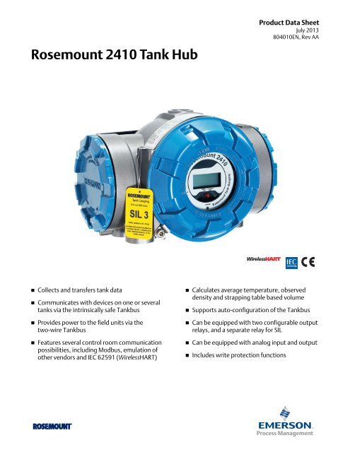
Rosemount 2410 Tank Hub - Emerson Process Management
Rosemount 2410 Tank Hub - Emerson Process Management
Rosemount 2410 Tank Hub - Emerson Process Management

You also want an ePaper? Increase the reach of your titles
YUMPU automatically turns print PDFs into web optimized ePapers that Google loves.
<strong>Rosemount</strong> <strong>2410</strong> <strong>Tank</strong> <strong>Hub</strong><br />
Product Data Sheet<br />
July 2013<br />
804010EN, Rev AA<br />
• Collects and transfers tank data<br />
• Communicates with devices on one or several<br />
tanks via the intrinsically safe <strong>Tank</strong>bus<br />
• Provides power to the field units via the<br />
two-wire <strong>Tank</strong>bus<br />
• Features several control room communication<br />
possibilities, including Modbus, emulation of<br />
other vendors and IEC 62591 (WirelessHART)<br />
• Calculates average temperature, observed<br />
density and strapping table based volume<br />
• Supports auto-configuration of the <strong>Tank</strong>bus<br />
• Can be equipped with two configurable output<br />
relays, and a separate relay for SIL<br />
• Can be equipped with analog input and output<br />
• Includes write protection functions
<strong>Rosemount</strong> <strong>Tank</strong>Radar<br />
Ext. pwr<br />
RS-232<br />
USB<br />
FBM 2180<br />
Tx<br />
Rx<br />
Lo - GAIN - Hi On - TERM - O f<br />
CIU858<br />
<strong>Rosemount</strong> <strong>2410</strong> July 2013<br />
<strong>Rosemount</strong> <strong>2410</strong> <strong>Tank</strong> <strong>Hub</strong>, for single or multiple tanks<br />
Communication between tanks and<br />
control room<br />
<strong>Rosemount</strong> <strong>2410</strong> is handling communication between the field<br />
devices and the control room, and it is available in two versions,<br />
for single or multiple tanks. It also feeds power to the units on<br />
the <strong>Tank</strong>bus.<br />
<strong>Tank</strong>bus<br />
<strong>2410</strong><br />
<strong>Tank</strong> <strong>Hub</strong><br />
The <strong>Rosemount</strong> <strong>2410</strong> <strong>Tank</strong> <strong>Hub</strong> handles communication from<br />
the field devices on the <strong>Tank</strong>bus to the control room.<br />
<strong>Tank</strong>bus communication<br />
Control<br />
Room<br />
The <strong>2410</strong> <strong>Tank</strong> <strong>Hub</strong> communicates with the devices on one or<br />
several tanks via the intrinsically safe <strong>Tank</strong>bus. The <strong>Tank</strong>bus<br />
complies with FISCO (Fieldbus Intrinsically Safe Concept)<br />
FOUNDATION fieldbus.<br />
Data handling and calculation<br />
<strong>Rosemount</strong> <strong>2410</strong> collects measurement values, such as level,<br />
temperature, and pressure.<br />
It calculates average temperature, observed density and<br />
strapping table based volume.<br />
Such data can be presented on the optional integrated back-lit<br />
display, a separate 2230 display, or be sent to <strong>Tank</strong>Master or a<br />
host system.<br />
Data security<br />
All tank hubs have a software write protection function. In<br />
addition, the <strong>Rosemount</strong> <strong>2410</strong> with display option is equipped<br />
with a hardware write protection switch.<br />
Control room communication<br />
<strong>Rosemount</strong> <strong>2410</strong> has slots for two independent communication<br />
boards (primary and secondary fieldbus) for TRL2 Modbus,<br />
RS485 Modbus, emulation and wireless communication.<br />
Existing host system from<br />
other vendor<br />
By using FISCO, there is no need to take entity parameters into<br />
considerations. This makes interconnection of devices easy.<br />
In addition, the available power from a FISCO power supply is<br />
higher compared to a conventional entity power supply. This<br />
enables connection of more devices on the <strong>Tank</strong>bus.<br />
Gauges from other<br />
vendor in an existing<br />
system<br />
<strong>2410</strong><br />
Autoconfiguration of <strong>Tank</strong>bus<br />
The <strong>2410</strong> supports auto-configuration of the <strong>Tank</strong>bus within the<br />
<strong>Rosemount</strong> <strong>Tank</strong> Gauging system. It acts as a FOUNDATION<br />
fieldbus master on the <strong>Tank</strong>bus, which means it identifies and<br />
auto-addresses the different field devices in the network,<br />
manages communication, and supervises the status of all<br />
connected devices.<br />
5900S<br />
5400 or<br />
5300<br />
Emulation: The tank hub enables replacement of old mechanical/servo<br />
gauges with 5900S level gauges, or 5300/5400 transmitters using the<br />
existing tank openings, field cabling, and control system.<br />
Contents<br />
<strong>Rosemount</strong> <strong>2410</strong> <strong>Tank</strong> <strong>Hub</strong>, for single or multiple tanks 2<br />
Ordering information . . . . . . . . . . . . . . . . . . . . . . . . . . 4<br />
Specifications . . . . . . . . . . . . . . . . . . . . . . . . . . . . . . . . . 9<br />
Product certifications . . . . . . . . . . . . . . . . . . . . . . . . 14<br />
Dimensional drawings . . . . . . . . . . . . . . . . . . . . . . . . 17<br />
2<br />
www.rosemount-tg.com
July 2013<br />
Power supply with built-in cable<br />
terminator<br />
<strong>Rosemount</strong> <strong>2410</strong> supplies power to the units on the <strong>Tank</strong>bus. It<br />
is equipped with an integrated FISCO-certified IS barrier, has<br />
power conditioner functionality, and built-in electronics for bus<br />
termination.<br />
A terminator is needed at each end of the <strong>Tank</strong>bus to ensure that<br />
the fieldbus network will have proper signal levels. All these<br />
features enable easy setup and installation of a <strong>Rosemount</strong> <strong>Tank</strong><br />
Gauging system.<br />
Wireless communication<br />
<strong>Rosemount</strong> <strong>2410</strong><br />
In tank gauging systems with wireless functionality the Smart<br />
Wireless THUM Adapter is used as an accessory device to the<br />
<strong>2410</strong> <strong>Tank</strong> <strong>Hub</strong>. The THUM Adapter acts as a wireless data link<br />
between the <strong>Tank</strong> <strong>Hub</strong> and a Smart Wireless Gateway in a<br />
WirelessHART field network. All available tank data such as level,<br />
temperature etc is transmitted via the wireless THUM.<br />
Output relay functionality<br />
<strong>Rosemount</strong> <strong>2410</strong> can be equipped with two solid state relays<br />
which can be configured to be controlled by level, temperature,<br />
and water level (Non-SIL in “<strong>Rosemount</strong> <strong>2410</strong> <strong>Tank</strong> <strong>Hub</strong> ordering<br />
information” on page 4). The output can be connected to an<br />
external system for alarm indication or process control. These<br />
relays are user configurable for normally open or closed<br />
operation.<br />
A third relay is dedicated for SIL overfill functionality. It is part of<br />
a separate SIL alarm channel, which has an independent<br />
software function, controlling the relay and providing extensive<br />
diagnostics. This relay is activated both if the alarm level is<br />
reached and/or if a device malfunction occurs.<br />
It operates in a normally closed mode, and the output can be<br />
connected to an emergency shut-down (ESD) system. The<br />
<strong>Rosemount</strong> <strong>Tank</strong> Gauging system is SIL 2 and SIL 3 certified for<br />
overfill prevention according to IEC 61508 Part 1-7.<br />
The <strong>2410</strong> <strong>Tank</strong> <strong>Hub</strong> connected to a Smart Wireless THUM Adapter<br />
with integrated connection box.<br />
Analog input/output<br />
The <strong>2410</strong> <strong>Tank</strong> <strong>Hub</strong> can be ordered with:<br />
• An analog input which can be used for connection of hybrid<br />
calculation pressure transmitters or<br />
• An analog output for connection to a host system<br />
www.rosemount-tg.com<br />
3
<strong>Rosemount</strong> <strong>2410</strong> July 2013<br />
Ordering information<br />
<strong>Rosemount</strong> <strong>2410</strong> <strong>Tank</strong> <strong>Hub</strong><br />
Additional information<br />
Specifications: page 9<br />
Certifications: page 14<br />
Dimensional drawings: page 17<br />
Table 1. <strong>Rosemount</strong> <strong>2410</strong> <strong>Tank</strong> <strong>Hub</strong> ordering information<br />
Model Product Description - Pos 1<br />
<strong>2410</strong> <strong>Tank</strong> <strong>Hub</strong><br />
<strong>Tank</strong>bus: Number of <strong>Tank</strong>s - Pos 2<br />
S<br />
M<br />
Single tank<br />
Multiple tanks (Maximum 5 <strong>Rosemount</strong> 5300/5400 transmitters can be connected to one <strong>Tank</strong> <strong>Hub</strong>)<br />
<strong>Tank</strong>bus: Power and Communication - Pos 3<br />
F<br />
Primary Fieldbus - Pos 4<br />
R<br />
Intrinsically safe FOUNDATION fieldbus (IEC 61158) power supply<br />
TRL2 Modbus<br />
4 RS485 Modbus<br />
E (1)<br />
Enraf Bi-phase Mark GPU<br />
Secondary Fieldbus - Pos 5<br />
R (2)<br />
E<br />
W (3)<br />
A (4)<br />
C (4)<br />
B (5)<br />
D (5)<br />
TRL2 Modbus<br />
Enraf Bi-phase Mark GPU<br />
WirelessHART (IEC 62591) connectivity (IS)<br />
Analog Output 4-20 mA/HART, active (Non-IS)<br />
Analog Output 4-20 mA/HART, active (IS)<br />
Analog Output 4-20 mA/HART, passive (Non-IS)<br />
Analog Output 4-20 mA/HART, passive (IS)<br />
6 (6) Analog Input 4-20 mA/HART, active (Non-IS)<br />
8 (6) Analog Input 4-20 mA/HART, active (IS)<br />
7 (7) Analog Input 4-20 mA/HART, passive (Non-IS)<br />
9 (7) Analog Input 4-20 mA/HART, passive (IS)<br />
F (8)<br />
None, but ready for upgrade of secondary bus<br />
0 None<br />
Relay Output (SIS/SIL) - Pos 6<br />
3 (9) (10) SIL 3-certified output as per IEC 61508<br />
2 (9) (11) SIL 2-certified output as per IEC 61508<br />
F (12) None, but ready for upgrade of safety certification (SIS)<br />
0 None<br />
Relay Output (Non-SIS/SIL) - Pos 7<br />
2 Two (2xSPST)<br />
1 One (1xSPST)<br />
F<br />
0 None<br />
None. Ready for upgrade of Relay Output (Non-SIS/SIL)<br />
4<br />
www.rosemount-tg.com
July 2013<br />
<strong>Rosemount</strong> <strong>2410</strong><br />
Table 1. <strong>Rosemount</strong> <strong>2410</strong> <strong>Tank</strong> <strong>Hub</strong> ordering information<br />
Integral Display - Pos 8<br />
1 LCD<br />
0 None<br />
Power Supply - Pos 9<br />
P<br />
Extended input range: 48-240 VAC at 50/60 Hz, and 24-48 VDC<br />
Software - Pos 10<br />
S<br />
Standard<br />
Hazardous Location Certification - Pos 11<br />
E1<br />
ATEX Flameproof with intrinsically safe output<br />
E2<br />
Brazil Inmetro Flameproof<br />
E5<br />
FM-US Explosionproof with intrinsically safe output<br />
E6<br />
FM-Canada Explosionproof with intrinsically safe output<br />
E7<br />
IECEx Flameproof with intrinsically safe output<br />
K1<br />
ATEX Flameproof + FM-US Explosionproof<br />
K3<br />
ATEX Flameproof + IECEx Flameproof<br />
K4<br />
FM-US Explosionproof + FM-Canada Explosionproof<br />
NA<br />
No hazardous location certification<br />
Custody Transfer Type Approval - Pos 12<br />
R (13) OIML R85 E 2008 performance certification<br />
C<br />
PTB Eich (Approval plate and sealing kit included)<br />
E<br />
TJA (Estonia W&M approval)<br />
N<br />
NMi (the Netherlands W&M approval)<br />
0 None<br />
Housing - Pos 13<br />
A Standard enclosure (Polyurethane-covered aluminum. IP 66/67)<br />
Cable/Conduit Connections - Pos 14<br />
1 (14) ½-14 NPT and ¾-14 NPT<br />
2 (15) M20 x 1.5 and M25 x 1.5 adapters<br />
G (16) Metal cable glands (½-14 and ¾-14 NPT)<br />
E (17) Eurofast male, ½-14 NPT and ¾-14 NPT<br />
M (17) Minifast male, ½-14 NPT and ¾-14 NPT<br />
Mechanical Installation - Pos 15<br />
P<br />
Mounting kit for both wall and pipe installation (1-2 in. vertical or horizontal pipes)<br />
W<br />
Mounting kit for wall installation<br />
0 None<br />
Options - none or multiple selections are possible<br />
QT (18) IEC 61508 certificate and FMEDA-data<br />
ST<br />
Engraved SST tag plate<br />
U1 TÜV/DIBt WHG Approval for Overfill protection (at least one relay must be selected, Pos 6 and/or Pos 7)<br />
Typical Model Number: <strong>2410</strong> S F R 0 3 2 1 P S E1 R A 1 P ST<br />
(1) Requires Secondary Fieldbus (Pos 5), code A-F, W, 0, 6-9.<br />
(2) Requires Primary Fieldbus (Pos 4) code R or 4.<br />
(3) Requires a separate Smart Wireless THUM Adapter (not included, to be ordered as a separate item). Maximum <strong>Tank</strong>bus (FF) current is reduced to 200 mA.<br />
(4) For connection to a 3rd party system. Integrated power supply. Maximum <strong>Tank</strong>bus current is reduced to 200 mA.<br />
(5) For connection to a 3rd party system.<br />
www.rosemount-tg.com<br />
5
<strong>Rosemount</strong> <strong>2410</strong> July 2013<br />
(6) For connection of a 3rd party instrument. Integrated power supply. Max <strong>Tank</strong>bus current reduced to 200 mA.<br />
(7) For connection of a 3rd party instrument.<br />
(8) Requires Relay Output (Pos 6) code 0 or F.<br />
(9) Requires Secondary Fieldbus (Pos 5), code 0 and <strong>Tank</strong>bus (Pos 2) code S, or<br />
Primary Fieldbus (Pos 4) code 4 and Secondary Fieldbus (Pos 5) code W, C, D, 8 or 9 and <strong>Tank</strong>bus (Pos 2) code S.<br />
(10) Requires <strong>Rosemount</strong> 5900S with safety Certification (SIS), code 3.<br />
(11) Requires <strong>Rosemount</strong> 5900S with safety Certification (SIS), code 2.<br />
(12) Requires Secondary Fieldbus (Pos 5), code 0 or F and <strong>Tank</strong>bus (Pos 2) code S.<br />
(13) Requires a <strong>Rosemount</strong> 5900S gauge with the corresponding custody transfer approval. A <strong>Rosemount</strong> 2230 display or <strong>Tank</strong>Master is required for an approved<br />
read-out.<br />
(14) Female thread. Includes 3 plugs.<br />
(15) Female thread. Includes 3 plugs, and 3 adapters.<br />
(16) Min. temperature -20 °C (-4 °F). ATEX / IECEx Exe approved. Includes 3 plugs, and 3 glands.<br />
(17) Includes 3 plugs.<br />
(18) Requires Relay Output (Pos 6) code 2 or 3 (SIL 3 or SIL 2).<br />
6<br />
www.rosemount-tg.com
July 2013<br />
<strong>Rosemount</strong> <strong>2410</strong><br />
<strong>Rosemount</strong> Smart Wireless THUM Adapter Assembly<br />
• 2-or 4-wire HART devices<br />
• Flexibility to meet your most demanding applications<br />
• Wireless output with >99% data reliability delivers rich HART data, protected by<br />
industry leading security<br />
• Gain access to additional HART information, such as diagnostics or multivariable data<br />
• Add wireless to almost any measurement point<br />
Additional information<br />
Specifications: page 9<br />
Certifications: page 14<br />
Dimensional drawings: page 17<br />
Table 2. <strong>Rosemount</strong> Smart Wireless THUM Adapter Assembly ordering information<br />
Model Product Description - Pos 1<br />
775 (1) Smart Wireless THUM Adapter<br />
Output - Pos 2<br />
X<br />
Housing - Pos 3<br />
D<br />
Wireless<br />
Aluminum<br />
Mounting Connection - Pos 4<br />
2 M20 conduit adapter<br />
Plantweb functionality - Pos 5<br />
1 HART data<br />
Certification - Pos 6<br />
NA<br />
I1<br />
I2<br />
I3<br />
I4<br />
I5<br />
I6<br />
I7<br />
N1<br />
N2<br />
N7<br />
IP<br />
IW<br />
IM<br />
No approval<br />
ATEX intrinsically safe<br />
INMETRO intrinsically safe<br />
NEPSI<br />
TIIS<br />
FM intrinsically safe, non-incendive<br />
CSA intrinsically safe<br />
IECEx intrinsically safe<br />
ATEX Type n<br />
INMETRO Type n<br />
IECEx Type n<br />
KOSHA intrinsically safe<br />
CCOE intrinsically safe<br />
GOST intrinsically safe<br />
Wireless Transmit Rate - Pos 7<br />
WA<br />
User configurable burst rate<br />
Operating Frequency and Protocol - Pos 8<br />
3 2.4 GHz DSSS, IEC 62591 (WirelessHART)<br />
www.rosemount-tg.com<br />
7
<strong>Rosemount</strong> <strong>2410</strong> July 2013<br />
Table 2. <strong>Rosemount</strong> Smart Wireless THUM Adapter Assembly ordering information<br />
Wireless Antenna - Pos 9<br />
WK<br />
Omnidirectional integral antenna<br />
SmartPower - Pos 10<br />
9 Power scavenging<br />
Device Connection - Pos 11<br />
T<br />
<strong>2410</strong> <strong>Tank</strong> <strong>Hub</strong> connection<br />
Cable / Conduit Connection - Pos 12<br />
0 None<br />
J (2) Metal cable gland M20 x 1.5<br />
F<br />
½ NPT Adapter (female thread)<br />
Options - none or multiple selections are possible<br />
PT<br />
Printed tag for unit identification<br />
Typical Model Number: 775 X D 2 1 I1 WA 3 WK 9 T F PT<br />
(1) Requires THUM Connection Box (Pos 11+).<br />
(2) Min. temperature -20 °C (-4 °F). ATEX / IECEx.<br />
8<br />
www.rosemount-tg.com
July 2013<br />
<strong>Rosemount</strong> <strong>2410</strong><br />
Specifications<br />
Table 3. <strong>Rosemount</strong> <strong>2410</strong> <strong>Tank</strong> <strong>Hub</strong> specifications<br />
General<br />
Product<br />
<strong>Rosemount</strong> <strong>2410</strong> <strong>Tank</strong> <strong>Hub</strong><br />
Single tank version<br />
• Supports one 5900S 2-in-1 gauge or two radar level gauges, type 5300, 5400, or 5900S<br />
• Total Observed Volume (TOV) calculation with 100-point strapping table<br />
Multiple tank version<br />
For a 5300/5400/5900S system configuration:<br />
• The software supports 16 field devices and 10 tanks per hub<br />
• Maximum five gauges, type 5300 or 5400 per hub<br />
• Hybrid calculations (mass and density) for up to three tanks<br />
• Total Observed Volume (TOV) calculation with 100-point strapping table for one tank<br />
The actual number of tanks/instruments a hub supports depends on the configuration, which types of<br />
units are connected and how many. For more information, see “Power budget” on page 12<br />
Examples of connected field devices Radar Level Gauges (type 5900S (1) , 5300, and 5400), 2240S Multi-input Temperature Transmitter,<br />
644 Temperature Transmitter, Temperature /Water Level Sensors, 3051S Scalable Pressure Transmitter,<br />
2230 Graphical Display<br />
Start-up time<br />
Less than 30 s<br />
Legal custody transfer type approval OIML R85:2008, and national certifications such as PTB, NMi etc<br />
Hazardous location certifications ATEX, FM-C, FM-US, IECEx, and national certifications. For details, see “Product certifications” on page 14<br />
and “<strong>Rosemount</strong> <strong>2410</strong> <strong>Tank</strong> <strong>Hub</strong> ordering information” on page 4<br />
Safety/overfill<br />
SIL 2 and SIL 3 certified (for more information see <strong>Rosemount</strong> Raptor <strong>Tank</strong> Gauging System Data<br />
Sheet (704010EN), and “Product certifications” on page 14)<br />
TÜV tested and WHG approved for overfill prevention. For more details, see “Product certifications” on<br />
page 14. For other national approvals, consult your local <strong>Rosemount</strong> <strong>Tank</strong> Gauging representative<br />
Communication / Display /Configuration<br />
<strong>Tank</strong>bus<br />
Fieldbus<br />
Relay outputs<br />
The intrinsically safe side of the <strong>Rosemount</strong> <strong>2410</strong> connects to the <strong>Tank</strong>bus which communicates with<br />
field devices on the tank using FOUNDATION fieldbus<br />
Primary fieldbus: <strong>Rosemount</strong> <strong>2410</strong> communicates with a host or a field communication unit via TRL2<br />
Modbus, RS485 Modbus, Enraf or HART<br />
Secondary fieldbus: TRL2 Modbus, Enraf (other options available soon), WirelessHART for Smart<br />
Wireless THUM Adapter<br />
SIL safety relay output: One SIL 2/SIL 3 certified relay is available for overfill prevention.<br />
This non-intrinsically safe solid state relay is closed/energized during normal operation<br />
Maximum voltage and current: 260 VAC/VDC, 80 mA<br />
Single pole<br />
Relay outputs (Non-SIL): Maximum two relays, controlled by 10 independent virtual relay functions<br />
which can be configured for different tanks and process variables.<br />
The two non-intrinsically safe solid state relays are user configurable for normally energized or<br />
de-energized operation.<br />
Maximum voltage and current: 350 VAC/VDC, 80 mA<br />
Single pole<br />
www.rosemount-tg.com<br />
9
<strong>Rosemount</strong> <strong>2410</strong> July 2013<br />
Table 3. <strong>Rosemount</strong> <strong>2410</strong> <strong>Tank</strong> <strong>Hub</strong> specifications<br />
Analog input/output<br />
Analog input<br />
Maximum number of input channels: 1<br />
Input Current range: 0-23 mA<br />
Configurable Min and Max alarm limits.<br />
Lift-off voltage (Passive IS and NON-IS): 10.5 V<br />
Max input voltage (Passive IS and NON-IS): 30 V<br />
Output voltage (Active):<br />
Non-IS: 22 ±2.0 V (open loop); 20.8 ±2.0 V @3,75 mA; 14.8 ±2.0 V @21.75 mA<br />
IS: 21 ±2.0 V (open loop); 18.8 ±2.0 V @3,75 mA; 8.2 ±2.0 V @21.75 mA<br />
See “Product certifications” for IS parameters<br />
HART master:<br />
Maximum 5 HART Slave Devices (Passive).<br />
Maximum 3 HART Slave Devices (Active).<br />
Analog output<br />
Maximum number of output channels: 1<br />
Output range: 3.5-23 mA<br />
SW Configurable High and Low Alarm Limits.<br />
Separate SW Configurable Alarms for process failures and HW failure.<br />
Low voltage and invalid loop current detection.<br />
Lift-off voltage (Passive IS and NON-IS): 10.5 V<br />
Max input voltage (Passive IS and NON-IS): 30 V<br />
Output voltage (Active):<br />
Non-IS: 22 ±2.0 V (open loop); 22.8 ±2.0 V @3,75 mA; 16.8 ±2.0 V @21.75 mA<br />
IS: 21 ±2.0 V (open loop); 20.8 ±2.0 V @3,75 mA; 10.2 ±2.0 V @21.75 mA<br />
See “Product certifications” for IS parameters<br />
HART slave configurable HART 5 or HART 7 (HCF registration is pending, HART 5 default)<br />
Integral display output variables The integral digital read-out display can toggle between: level, level rate, ullage, signal strength, volume<br />
(TOV), liquid average temperature, 1-16 spot temperature, vapor average temperature, ambient<br />
temperature, free water level, vapor pressure, liquid pressure, air pressure, observed density, reference<br />
density, and flow rate.<br />
Display output units (2) Level, free water level, and ullage: meter, millimeter, feet, or imperial 1/16<br />
Level rate: meter/second, meter/hour, feet/second, or feet/hour<br />
Flow rate: meter³/hour, liter/minute, barrel/hour, or US gallon/hour<br />
Total Observed Volume (TOV): meter³, liters, barrel, or US gallon<br />
Temperature: °F, °C, or °K<br />
Pressure: psi, psiA, psiG, bar, barA or barG, atm, Pa, or kPa<br />
Density: kg/m³, °API, or 60/60DegF<br />
Signal strength: mV<br />
Configuration tools<br />
<strong>Rosemount</strong> <strong>Tank</strong>Master<br />
Autoconfiguration support<br />
Yes (<strong>Tank</strong>bus addressing)<br />
Electric<br />
Power supply (nominal values) 24-48 VDC (-15% to +10%)<br />
48-240 VAC (-15% to +10%), 50/60 Hz<br />
Power consumption<br />
Max. 20 W depending on configuration<br />
<strong>Tank</strong>bus cabling<br />
0.5-1.5 mm² (AWG 22-16), twisted shielded pairs<br />
Power and relay cabling<br />
0.5-2.5 mm² (AWG 22-14), twisted shielded pairs<br />
Maximum <strong>Tank</strong>bus cable lengths Depends on cable. For details see the <strong>Rosemount</strong> Raptor <strong>Tank</strong> Gauging System Data Sheet (704010EN)<br />
Built-in <strong>Tank</strong>bus terminator<br />
Yes (to be disconnected if required)<br />
10<br />
www.rosemount-tg.com
July 2013<br />
<strong>Rosemount</strong> <strong>2410</strong><br />
Table 3. <strong>Rosemount</strong> <strong>2410</strong> <strong>Tank</strong> <strong>Hub</strong> specifications<br />
Mechanical<br />
Housing material<br />
Polyurethane-covered die-cast aluminum<br />
Cable entry (connection/glands) Non-IS side: Two ½ - 14 NPT and Two ¾ - 14 NPT entries for cable glands or conduits<br />
IS side: Two ½ - 14 NPT entries for cable glands or conduits<br />
Three metal plugs to seal any unused ports are included in the delivery<br />
Optional:<br />
• M20 x 1.5 and M25 x 1.5 conduit / cable adapter<br />
• Cable glands in metal (½ - 14 NPT and ¾ - 14 NPT)<br />
• 4-pin male Eurofast connector or A size Mini 4-pin male Minifast connector<br />
Installation<br />
Can be installed on a 33.4-60.3 mm (1-2 in.) diameter pipe or wall<br />
Dimensions See “Dimensional drawings” on page 17<br />
Weight<br />
Environment<br />
4.7 kg (10.4 lbs)<br />
Ambient temperature<br />
-40 to 70 °C (-40 to 158 °F). Minimum start-up temperature is -50 °C (-58 °F).<br />
With LCD display: -25 to 70 °C (-13 to 158 °F)<br />
Storage temperature<br />
-50 to 85 °C (-58 to 185 °F)<br />
With LCD display: -40 to 85 °C (-40 to 185 °F)<br />
Humidity<br />
0 - 100% relative humidity<br />
Ingress protection IP 66 and IP 67 (Nema 4X)<br />
Metrology sealing possibility<br />
Yes<br />
Write protect switch<br />
Yes<br />
Transient / built-in lightning protection According to IEC 61000-4-5, level 4 kV line to ground. Complies with IEEE 587 Category B transient<br />
protection and IEEE 472 surge protection<br />
(1) One <strong>Rosemount</strong> 5900S with 2-in-1 solution or maximum two <strong>Rosemount</strong> 5900S gauges installed on separate tanks can be connected to one tank hub. If two<br />
<strong>Rosemount</strong> 5900S gauges are installed on the same tank, two separate tank hubs are required.<br />
(2) Density, mass, and more volume parameters are calculated in <strong>Rosemount</strong> <strong>Tank</strong>Master (GOV, GSV, NSV, WIA/WIV).<br />
Table 4. Fieldbus combination matrix<br />
Primary fieldbus options<br />
TRL2 RS485 ENRAF A_OUT PASSIVE (NON-IS) A_IN PASSIVE (NON-IS)<br />
Code R 4 E B 7<br />
TRL2 R Yes Yes No No No<br />
ENRAF E Yes Yes No No No<br />
WIRELESSHART (IEC62591) W Yes SIL Yes Yes Yes<br />
Secondary fieldbus options<br />
A_OUT ACTIVE (IS) C Yes SIL Yes No No<br />
A_OUT ACTIVE (NON-IS) A Yes Yes Yes No No<br />
A_OUT PASSIVE (IS) D Yes SIL Yes No No<br />
A_OUT PASSIVE (NON-IS) B Yes Yes Yes No No<br />
A_IN ACTIVE (IS) 8 Yes SIL Yes No No<br />
A_IN ACTIVE (NON-IS) 6 Yes Yes Yes No No<br />
A_IN PASSIVE (IS) 9 Yes SIL Yes No No<br />
A_IN PASSIVE (NON-IS) 7 Yes Yes Yes No No<br />
A_IN ACTIVE (IS) 8 Yes SIL Yes No No<br />
None 0 SIL SIL SIL No No<br />
READY FOR UPGRADE F Yes Yes Yes No No<br />
SIL = Primary fieldbus and secondary fieldbus in combination = Yes, and can be combined<br />
with SIL<br />
www.rosemount-tg.com<br />
11
<strong>Rosemount</strong> <strong>2410</strong> July 2013<br />
Table 5. Power budget<br />
Field device<br />
5900S Radar Level Gauge<br />
5900S Radar Level Gauge, 2-in-1 solution<br />
Figure 1. Cable diameter<br />
Power consumption<br />
50 mA<br />
100 mA<br />
5300 or 5400 Series Radar Level Transmitter 21 mA<br />
<strong>Rosemount</strong> 2230 Graphical Field Display<br />
<strong>Rosemount</strong> 2240S Multi-input Temperature Transmitter<br />
<strong>Rosemount</strong> 644 Temperature Transmitter<br />
<strong>Rosemount</strong> 3051S, and <strong>Rosemount</strong> 2051 Pressure Transmitters<br />
30 mA<br />
30 mA including 565, 566 and<br />
765 temperature sensors<br />
11 mA<br />
18 mA<br />
The total cable distance A+B+C+D must not exceed the values given in Table 6.<br />
D<br />
C<br />
B<br />
A<br />
D<br />
C<br />
C<br />
D<br />
A<br />
B<br />
B<br />
A<br />
Table 6. Allowed cabling distances for different system configurations<br />
Cable diameter Loop resistance Maximum cabling distance from power source to all devices on the tank<br />
with maximum power<br />
usage of 250 mA.<br />
with typical power usage of<br />
128 mA for 5900S, 2240S,<br />
2230, 3051S.<br />
with typical power usage of<br />
178 mA for 5900S 2-in-1,<br />
2240S, 2230, 3051S.<br />
Distance in m (ft) Distance in m (ft)<br />
Distance in m (ft)<br />
20 AWG (0.5 mm²) 66 /km 212 (695) 414 (1358) 298 (978)<br />
18 AWG (0.75 mm²) 42 /km 333 (1092) 651 (2136) 468 (1535)<br />
17 AWG (1.0 mm²) 33 /km 424 (1391) 829 (2720) 596 (1955)<br />
16 AWG (1.5 mm²) 26 /km 538 (1765) 1000 (3281) 756 (2480)<br />
12<br />
www.rosemount-tg.com
July 2013<br />
<strong>Rosemount</strong> <strong>2410</strong><br />
Table 7. Smart Wireless THUM Adapter Assembly specifications<br />
General<br />
Product<br />
Transmission range<br />
Hazardous location certifications<br />
Communication<br />
Communication protocol<br />
Radio characteristics<br />
Update rate<br />
Smart Wireless THUM Adapter. The THUM allows WirelessHART communication according to the IEC<br />
62591 standard between the device it is connected to and the Smart Wireless Gateway. The THUM is<br />
integrated with a connection box<br />
Application dependent. Consult factory<br />
FM, CSA, and ATEX (see “<strong>Rosemount</strong> Smart Wireless THUM Adapter Assembly ordering information”<br />
on page 7) and the Smart Wireless THUM Product Data Sheet (document number 00813-0100-4075)<br />
IEC 62591 (WirelessHART)<br />
• Standard IEEE 802.15.4 radio<br />
• 2.4 GHz ISM band sliced into 16 radio-channels<br />
• Continually “hop” across channels to avoid interference and increase reliability<br />
• Direct sequence spread spectrum (DSSS) delivers high reliability in challenging radio environment<br />
User selectable, 8 seconds to 60 minutes<br />
Electric<br />
Power supply<br />
Powered by <strong>Rosemount</strong> <strong>2410</strong> tank hub<br />
Output cabling<br />
Shielded twisted pair wiring, 0.5-2.5 mm² (AWG 22-14). Maximum cable length depends on cable<br />
characteristics<br />
IS parameters U i =30 V, I i =200 mA, P i =1.0 W, C i =L i =0<br />
Mechanical<br />
Housing / enclosure<br />
Polyurethane painted, low-copper aluminum housing<br />
Cable entry (connection/glands) One M20x1.5 entry for cable gland or conduit adapter<br />
Optional:<br />
• Metal cable gland M20x1.5<br />
• ½ NPT adapter (female thread)<br />
Installation<br />
The THUM can be installed on a vertical or horizontal 1 to 2-in. pipe, away from the <strong>Tank</strong> <strong>Hub</strong> at the best<br />
possible tank roof position. It should be positioned approximately 2 m (6 ft) or more from any large<br />
structure or conductive surface<br />
Dimensions See “Dimensional drawings” on page 17<br />
Antenna<br />
Weight<br />
Environment<br />
Polybutadine terephthalate (PBT) / polycarbonate (PC) integrated omnidirectional antenna<br />
Connection box and THUM adapter: 2.0 kg (4.4 lbs.)<br />
Ambient temperature<br />
Storage temperature<br />
Humidity<br />
Ingress protection<br />
Electromagnetic compatibility (EMC)<br />
Approvals<br />
-40 to 85 °C (-40 to 185 °F)<br />
-40 to 85 °C (-40 to 185 °F)<br />
0 - 100% relative humidity<br />
IP 66 and NEMA 4X<br />
Meets all relevant requirements of EN 61326-1 (2006) and (2004/108/EC). The THUM and tank hub<br />
should be installed with shielded wiring<br />
FCC part 15, R&TTE (99/5/EC), and IC (RSS210). See above for hazardous location certifications<br />
NOTE<br />
For more information, see the Smart Wireless THUM Adapter Product Data Sheet<br />
(document number 00813-0100-4075)<br />
www.rosemount-tg.com<br />
13
<strong>Rosemount</strong> <strong>2410</strong> July 2013<br />
Product certifications<br />
CE mark<br />
Complies with applicable EU directives (EMC, ATEX)<br />
Ordinary location certification<br />
Complies with FM 3810:2005 and CSA: C22.2 No. 1010.1<br />
OIML R85:2008<br />
The OIML metrology certificate, issued by the SP Technical Research<br />
Institute of Sweden, covers the Raptor <strong>Tank</strong> Gauging system, including<br />
the level gauges equipped with different antennas.<br />
Certificate number is R85/2008-SE-11.01.<br />
HART/4-20 mA Entity IS I/O Option:<br />
Active Current Loop:<br />
0575<br />
II 2(1) G<br />
Ex de [ia IIC] IIB T4 (-50 °C T a +70 °C)<br />
U o =23.1 VDC, I o =95.3 mA, P o =550 mW<br />
Group IIC: C o 0.14 µF, L o 3.9 mH<br />
Group IIB: C o 1.0 µF, L o 15 mH<br />
Group IIA: C o 3.67 µF, L o 33 mH<br />
Passive Current Loop:<br />
0575<br />
II 2(2) G<br />
Ex de [ib IIC] IIB T4 (-50 °C T a +70 °C)<br />
U i =30.0 VDC, I i =300 mA, C i =0 µF, L i =0 mH<br />
SIL certification<br />
The SIL safety certificate, issued by exida in Switzerland, includes the SIL<br />
alarm channel within the 5900S radar level gauge and the <strong>2410</strong> <strong>Tank</strong><br />
<strong>Hub</strong>. Both units are SIL 2 and SIL 3 capable according to IEC 61508, parts<br />
1-7.<br />
Certificate number is <strong>Rosemount</strong> 091243 P0017 C001.<br />
German WHG certification<br />
The certificate for the 5900S radar level gauge and the <strong>2410</strong> <strong>Tank</strong> <strong>Hub</strong> is<br />
issued by DIBt (Deutsches Institute für Bautechnik) according to the<br />
German WHG regulations for overfill prevention. It is based on technical<br />
evaluation and testing conducted by TÜV NORD CERT GmbH.<br />
Certificate number is Z-65.16-500.<br />
Hazardous location certifications for<br />
<strong>Rosemount</strong> <strong>2410</strong><br />
European ATEX Directive Information<br />
EC-Type Examination Certificate Number: FM10ATEX0012<br />
Control Drawing: 9240040-901<br />
E1 (1)<br />
Flameproof with Intrinsically Safe Output<br />
US Factory Mutual (FM-US) certification<br />
Certificate of Compliance: 3035492<br />
Control Drawing: 9240040-901<br />
E5 (1) Explosionproof with Intrinsically Safe Output<br />
Temperature Class T4<br />
Ambient Temperature Limits -50 °C to +70 °C<br />
FISCO Power Supply<br />
Explosionproof Class I, Division 1, Groups C, and D<br />
Dust-ignitionproof Class II and III, Division 1, Groups E, F, and G<br />
Associated Intrinsically Safe Class I, Division 1, Groups C and D<br />
Class I Zone 1 AEx de [ib] IIB<br />
U o =15 VDC, I o =354 mA, P o =5.32 W<br />
HART/4-20 mA Entity IS I/O Option:<br />
Active Current Loop:<br />
XP-AIS CL I, DIV. 1 GP C & D<br />
AEx de[ia IIC] IIB<br />
U o =23.1 VDC, I o =95.3 mA, P o =550 mW<br />
Group IIC: C o 0.14 µF, L o 3.9 mH<br />
Group C, IIB: C o 1.0 µF, L o 15 mH<br />
Group D, IIA: C o 3.67 µF, L o 33 mH<br />
Passive Current Loop:<br />
AEx de [ib IIC] IIB<br />
U i =30.0 VDC, I i =300 mA, C i =0 µF, L i =0 mH<br />
FISCO Power Supply:<br />
0575<br />
II 2(2) G<br />
Ex de [ib] IIB T4 (-50 °C T a +70 °C)<br />
U o =15 VDC, I o =354 mA, P o =5.32 W<br />
U m =250 VDC<br />
(1) Ordering information model code for hazardous location certification,<br />
see page 5<br />
14<br />
www.rosemount-tg.com
July 2013<br />
Canadian Factory Mutual (FM-C) certification<br />
Certificate of Compliance: 3035492C<br />
Control Drawing: 9240040-901<br />
E6 (1) Explosionproof with Intrinsically Safe Output<br />
Temperature Class T4<br />
Ambient Temperature Limits -50 °C to +70 °C<br />
FISCO Power Supply:<br />
Explosionproof Class I, Division 1, Groups C, and D<br />
Dust-ignitionproof Class II and III, Division 1, Groups E, F, and G<br />
Associated Intrinsically Safe Class I, Division 1, Groups C and D<br />
Class I Zone 1 Ex de[ib] IIB<br />
U o =15 VDC, I o =354 mA, P o =5.32 W<br />
HART/4-20 mA Entity IS I/O Option:<br />
Active Current Loop:<br />
XP-AIS CL I, DIV. 1 GP C & D<br />
Ex de[ia IIC] IIB<br />
U o =23.1 VDC, I o =95.3 mA, P o =550 mW<br />
Group IIC: C o 0.14 µF, L o 3.9 mH<br />
Group C, IIB: C o 1.0 µF, L o 15 mH<br />
Group D, IIA: C o 3.67 µF, L o 33 mH<br />
Passive Current Loop:<br />
Ex de [ib IIC] IIB<br />
U i =30.0 VDC, I i =300 mA, C i =0 µF, L i =0 mH<br />
IECEx certification<br />
Certification of Conformity Number: IECEx FMG 10.0005<br />
Control Drawing: 9240040-901<br />
E7 (1)<br />
Flameproof with Intrinsically Safe Output (FISCO)<br />
FISCO Power Supply:<br />
Ex de [ib] IIB Gb T4 (-50 °C T a +70 °C)<br />
U o =15 VDC, I o =354 mA, P o =5.32 W, U m =250 VDC<br />
HART/4-20 mA Entity IS I/O Option:<br />
Active Current Loop:<br />
Ex de [ia IIC Ga] IIB Gb T4 (-50 °C T a +70 °C)<br />
U o =23.1 VDC, I o =95.3 mA, P o =550 mW<br />
Group IIC: C o 0.14 µF, L o 3.9 mH<br />
Group IIB: C o 1.0 µF, L o 15 mH<br />
Group IIA: C o 3.67 µF, L o 33 mH<br />
Passive Current Loop:<br />
Ex de [ib IIC Gb] IIB Gb T4 (-50 °C T a +70 °C)<br />
U i =30.0 VDC, I i =300 mA, C i =0 µF, L i =0 mH<br />
Combination Approvals<br />
K1=E1+E5 (ATEX + FM-US)<br />
K3=E1+E7 (ATEX + IECEx)<br />
K4=E5+E6 (FM-US+FM-C)<br />
For more information on product certificates, refer to the <strong>Rosemount</strong><br />
<strong>2410</strong> Reference manual (document number 300530EN).<br />
Hazardous location certifications for<br />
Smart Wireless THUM<br />
CE mark<br />
Complies with applicable EU directives (EMC, ATEX)<br />
Special conditions for safe use (x), ATEX & IECEX<br />
<strong>Rosemount</strong> <strong>2410</strong><br />
The surface resistivity of the antenna is greater than one gigaohm.<br />
To avoid electrostatic charge build-up, it must not be rubbed or<br />
cleaned with solvents or a dry cloth.<br />
The enclosure is made of aluminum alloy and given a protective<br />
polyurethane paint finish; however, care should be taken to<br />
protect it from impact or abrasion if located in a zone 0.<br />
European Directive information<br />
The EC declaration of conformity for all applicable European directives<br />
for this product can be found at www.rosemount.com. A hard copy may<br />
be obtained by contacting an <strong>Emerson</strong> <strong>Process</strong> <strong>Management</strong><br />
representative.<br />
ATEX DIRECTIVE (94/9/EC)<br />
<strong>Emerson</strong> <strong>Process</strong> <strong>Management</strong> complies with the ATEX Directive.<br />
ELECTROMAGNETIC COMPABILITY (EMC) (2004/108/EC)<br />
<strong>Emerson</strong> <strong>Process</strong> <strong>Management</strong> complies with the EMC Directive.<br />
RADIO AND TELECOMMUNICATIONS TERMINAL EQUIPMENT DIRECTIVE<br />
(R&TTE) (1999/5/EC)<br />
<strong>Emerson</strong> <strong>Process</strong> <strong>Management</strong> complies with the R&TTE directive.<br />
Telecommunication compliance<br />
All wireless devices require certification to ensure that they adhere to<br />
regulations regarding the use of the RF spectrum. Nearly every country<br />
requires this type of product certification. <strong>Emerson</strong> is working with<br />
governmental agencies around the world to supply fully compliant<br />
products and remove the risk of violating country directives or laws<br />
governing wireless device usage.<br />
FCC and IC<br />
This device complies with Part 15 of the FCC Rules. Operation is subject<br />
to the following conditions: This device may not cause harmful<br />
interference. This device must accept any interference received,<br />
including interference that may cause undesired operation. This device<br />
must be installed to ensure a minimum antenna separation distance of<br />
20 cm (8 in.) from all persons.<br />
Ordinary location certification for FM<br />
As standard, the transmitter has been examined and tested to<br />
determine that the design meets basic electrical, mechanical, and fire<br />
protection requirements by FM, a nationally recognized testing<br />
laboratory (NRTL) as accredited by the Federal Occupational Safety and<br />
Health Administration (OSHA).<br />
European ATEX Directive information<br />
I1 (1)<br />
ATEX Intrinsic Safety<br />
Certificate No.: Baseefa09ATEX0125X II 1G<br />
Ex ia IIC T4 (-50 °C T amb 70 °C)<br />
IP66. U i =30 V, L i =200 mA, P i =1.0 W, C i =0, L i =0<br />
1180<br />
(1) Ordering information model code for certification, see page 7<br />
www.rosemount-tg.com<br />
15
<strong>Rosemount</strong> <strong>2410</strong> July 2013<br />
N1 (1) ATEX Type n<br />
Certificate No.: Baseefa09ATEX0131<br />
Ex na IIC T4 (-50 °C T amb 70 °C)<br />
IP66. U i =45 Vdc max.<br />
1180<br />
Factory Mutual (FM) Approvals<br />
II 3G<br />
For more information, see the Smart Wireless THUM Adapter product<br />
data sheet (document number 00813-0100-4075)<br />
I5 (1)<br />
FM Intrinsic Safety and Non-incendive<br />
Intrinsically Safe for Class I/II/III, Division 1,<br />
Groups A, B, C, D, E, F, and G.<br />
Zone Marking: Class I, Zone 0, AEx ia llC<br />
Temperature Codes T4 (-50 °C T amb 70 °C)<br />
Non-incendive for Class I, Division 2, Groups A, B, C, and D.<br />
Intrinsically safe and non-incendive when installed according to<br />
<strong>Rosemount</strong> drawing 9240040-901<br />
Enclosure Type 4X/IP66<br />
CSA - Canadian Standards Association<br />
I6 (1)<br />
CSA Intrinsic Safety<br />
Intrinsically Safe for Class I, Division 1, Groups A, B, C, and D.<br />
T3C (-50 °C T amb 70 °C)<br />
Intrinsically safe when installed according to <strong>Rosemount</strong> drawing<br />
9240040-901<br />
Suitable for Class I, Division 2, Groups A, B, C, and D<br />
IECEx certifications<br />
I7 (1)<br />
IECEx Intrinsic Safety<br />
Certificate No.: IECEx BAS 09.0050X<br />
Ex ia IIC T4 (-50 °C T amb 70 °C)<br />
IP66. U i =30 V, L i =200 mA, P i =1.0 W, C i =0, L i =0<br />
N7 (1) IECEx Type n<br />
Certificate No.: IECEx BAS 09.0058<br />
Ex na IIC T4 (-50 °C T amb 70 °C)<br />
IP66. U i =45 Vdc max.<br />
INMETRO certifications<br />
I2 (1)<br />
INMETRO Intrinsic Safety<br />
BR-Ex ia IIC T4 (-50 °C T amb 70 °C) Ga<br />
N2 (1) INMETRO Type n<br />
BR-Ex na IIC T4 Gc(-50 °C T amb 70 °C)<br />
China (NEPSI) certifications<br />
I3 (1)<br />
China (NEPSI) Intrinsic Safety<br />
Ex ia IIC T4<br />
CCoE certifications<br />
IW (1) Intrinsic Safety<br />
Ex ia IIC T4<br />
KOSHA certifications<br />
IP (1)<br />
Intrinsic Safety<br />
Ex ia IIC T4<br />
GOST certifications<br />
IM (1)<br />
Intrinsically Safe<br />
Ex ia IIC T4 (-50 °C T amb 70 °C)<br />
Ex na IIC T4 (-50 °C T amb 70 °C)<br />
IP66<br />
16<br />
www.rosemount-tg.com
July 2013<br />
Dimensional drawings<br />
<strong>Rosemount</strong> <strong>2410</strong><br />
Dimensions are in mm (inches)<br />
Figure 2. <strong>Rosemount</strong> <strong>2410</strong> <strong>Tank</strong> <strong>Hub</strong> dimensions<br />
193 (7.6) 254 (10)<br />
164 (6.5)<br />
Figure 3. Smart Wireless THUM Adapter Assembly dimensions<br />
Vertical orientation of<br />
THUM Adapter<br />
145 (5.7)<br />
30 (1.2)<br />
120 (4.7)<br />
82 (3.2)<br />
106 (4.2)<br />
122 (4.8)<br />
Mounting kit for<br />
vertical or horizontal<br />
installation<br />
Fits 33.4-60.3 mm (1-2 in.) pipe diameters<br />
www.rosemount-tg.com<br />
17
<strong>Rosemount</strong> <strong>2410</strong><br />
804010EN, Rev AA<br />
Product Data Sheet<br />
July 2013<br />
<strong>Emerson</strong> <strong>Process</strong> <strong>Management</strong><br />
<strong>Rosemount</strong> <strong>Tank</strong> Gauging<br />
Box 130 45<br />
SE-402 51 Göteborg<br />
SWEDEN<br />
Tel: +46 31 337 00 00<br />
Fax: +46 31 25 30 22<br />
E-mail: sales.rtg@emerson.com<br />
www.rosemount-tg.com<br />
<strong>Emerson</strong> <strong>Process</strong> <strong>Management</strong><br />
<strong>Rosemount</strong> <strong>Tank</strong> Gauging North America Inc.<br />
6005 Rogerdale Road<br />
Mail Stop NC 136<br />
77072 TX Houston<br />
United States<br />
Primary Phone: +1 281 988 4000<br />
Secondary Phone: +1 800 722 2865<br />
E-mail: sales.rtg.hou@emerson.com<br />
<strong>Emerson</strong> <strong>Process</strong> <strong>Management</strong><br />
Asia Pacific Pte Ltd<br />
1 Pandan Crescent<br />
SINGAPORE 128461<br />
Tel: +65 6777 8211<br />
Fax: +65 6777 0947<br />
Email: specialist-itg.rmt-ap@ap.emersonprocess.com<br />
<strong>Emerson</strong> <strong>Process</strong> <strong>Management</strong><br />
<strong>Rosemount</strong> <strong>Tank</strong> Gauging Middle East & Africa.<br />
P. O Box 20048<br />
Manama<br />
Bahrain<br />
Tel: +973 1722 6610<br />
Fax: +973 1722 7771<br />
E-mail: rtgmea.sales@emerson.com<br />
Standard Terms and Conditions of Sale can be found at www.rosemount.com\terms_of_sale<br />
The <strong>Emerson</strong> logo is a trade mark and service mark of <strong>Emerson</strong> Electric Co.<br />
<strong>Rosemount</strong> and the <strong>Rosemount</strong> logotype are registered trademarks of <strong>Rosemount</strong> Inc.<br />
PlantWeb is a registered trademark of one of the <strong>Emerson</strong> <strong>Process</strong> <strong>Management</strong> group of companies.<br />
HART and WirelessHART are registered trademarks of the HART Communication Foundation<br />
All other marks are the property of their respective owners.<br />
© 2013 <strong>Rosemount</strong> Inc. All rights reserved.