CLIOwin 6.5 PCI User's Manual - Audiomatica Srl
CLIOwin 6.5 PCI User's Manual - Audiomatica Srl
CLIOwin 6.5 PCI User's Manual - Audiomatica Srl

You also want an ePaper? Increase the reach of your titles
YUMPU automatically turns print PDFs into web optimized ePapers that Google loves.
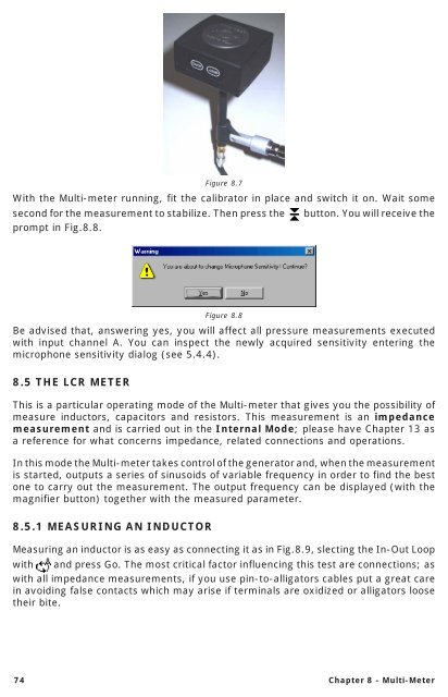
Figure 8.7<br />
With the Multi-meter running, fit the calibrator in place and switch it on. Wait some<br />
second for the measurement to stabilize. Then press the button. You will receive the<br />
prompt in Fig.8.8.<br />
Figure 8.8<br />
Be advised that, answering yes, you will affect all pressure measurements executed<br />
with input channel A. You can inspect the newly acquired sensitivity entering the<br />
microphone sensitivity dialog (see 5.4.4).<br />
8.5 THE LCR METER<br />
This is a particular operating mode of the Multi-meter that gives you the possibility of<br />
measure inductors, capacitors and resistors. This measurement is an impedance<br />
measurement and is carried out in the Internal Mode; please have Chapter 13 as<br />
a reference for what concerns impedance, related connections and operations.<br />
In this mode the Multi-meter takes control of the generator and, when the measurement<br />
is started, outputs a series of sinusoids of variable frequency in order to find the best<br />
one to carry out the measurement. The output frequency can be displayed (with the<br />
magnifier button) together with the measured parameter.<br />
8.5.1 MEASURING AN INDUCTOR<br />
Measuring an inductor is as easy as connecting it as in Fig.8.9, slecting the In-Out Loop<br />
with and press Go. The most critical factor influencing this test are connections; as<br />
with all impedance measurements, if you use pin-to-alligators cables put a great care<br />
in avoiding false contacts which may arise if terminals are oxidized or alligators loose<br />
their bite.<br />
74 Chapter 8 - Multi-Meter