Owners Manual - AudioMaster
Owners Manual - AudioMaster
Owners Manual - AudioMaster

Create successful ePaper yourself
Turn your PDF publications into a flip-book with our unique Google optimized e-Paper software.
®<br />
640/641<br />
User <strong>Manual</strong>
IMPORTANT SAFETY INSTRUCTIONS<br />
CAUTION<br />
RISK OF ELECTRIC SHOCK<br />
DO NOT OPEN<br />
ATTENTION: RISQUE DE CHOC ELECTRIQUE - NE PAS OUVRIR<br />
WARNING: TO REDUCE THE RISK OF FIRE OR ELECTRIC<br />
SHOCK DO NOT EXPOSE THIS EQUIPMENT TO RAIN OR MOISTURE<br />
The symbols shown above are internationally accepted<br />
symbols that warn of potential hazards with electrical<br />
products. The lightning flash with arrowpoint in an equilateral<br />
triangle means that there are dangerous voltages<br />
present within the unit. The exclamation point in an equilateral<br />
triangle indicates that it is necessary for the user to<br />
refer to the owner’s manual.<br />
These symbols warn that there are no user serviceable<br />
parts inside the unit. Do not open the unit. Do not<br />
attempt to service the unit yourself. Refer all servicing to<br />
qualified personnel. Opening the chassis for any reason<br />
will void the manufacturer’s warranty. Do not get the unit<br />
wet. If liquid is spilled on the unit, shut it off immediately<br />
and take it to a dealer for service. Disconnect the unit<br />
during storms to prevent damage.<br />
KEEP THESE INSTRUCTIONS<br />
HEED ALL WARNINGS<br />
FOLLOW ALL INSTRUCTIONS<br />
WARNING FOR YOUR PROTECTION<br />
READ THE FOLLOWING:<br />
DO NOT USE THIS APPARATUS NEAR WATER<br />
CLEAN ONLY WITH A DRY CLOTH.<br />
DO NOT BLOCK ANY OF THE VENTILATION OPENINGS. INSTALL IN ACCORDANCE WITH<br />
THE MANUFACTURER’S INSTRUCTIONS.<br />
DO NOT INSTALL NEAR ANY HEAT SOURCES SUCH AS RADIATORS, HEAT REGISTERS,<br />
STOVES, OR OTHER APPARATUS (INCLUDING AMPLIFIERS) THAT PRODUCE HEAT.<br />
ONLY USE ATTACHMENTS/ACCESSORIES SPECIFIED BY THE MANUFACTURER.<br />
UNPLUG THIS APPARATUS DURING LIGHTNING STORMS OR WHEN UNUSED FOR LONG<br />
PERIODS OF TIME.<br />
Do not defeat the safety purpose of the polarized or grounding-type plug. A polarized<br />
plug has two blades with one wider than the other. A grounding type plug has<br />
two blades and a third grounding prong. The wide blade or third prong are provided<br />
for your safety. If the provided plug does not fit your outlet, consult an electrician<br />
for replacement of the obsolete outlet.<br />
SAFETY INSTRUCTIONS<br />
NOTICE FOR CUSTOMERS IF YOUR UNIT IS EQUIPPED<br />
WITH A POWER CORD.<br />
WARNING: THIS APPLIANCE MUST BE EARTHED.<br />
CONNECT ONLY TO A MAINS SOCKET OUTLET WITH<br />
PROTECTIVE EARTHING CONNECTION.<br />
The cores in the mains lead are coloured in accordance with<br />
the following code:<br />
GREEN and YELLOW - Earth BLUE - Neutral BROWN - Live<br />
As colours of the cores in the mains lead of this appliance may<br />
not correspond with the coloured markings identifying the terminals<br />
in your plug, proceed as follows:<br />
• The core which is coloured green and yellow must be connected<br />
to the terminal in the plug marked with the letter E, or<br />
with the earth symbol, or coloured green, or green and yellow.<br />
• The core which is coloured blue must be connected to the<br />
terminal marked N or coloured black.<br />
• The core which is coloured brown must be connected to the<br />
terminal marked L or coloured red.<br />
This equipment may require the use of a different line cord,<br />
attachment plug, or both, depending on the available power<br />
source at installation. If the attachment plug needs to be<br />
changed, refer servicing to qualified service personnel who<br />
should refer to the table below. The green/yellow wire shall be<br />
connected directly to the units chassis.<br />
CONDUCTOR<br />
L<br />
N<br />
E<br />
LIVE<br />
NEUTRAL<br />
Normal<br />
BROWN<br />
BLUE<br />
EARTH GND GREEN/YEL<br />
WIRE COLOR<br />
Alt<br />
BLACK<br />
WHITE<br />
GREEN<br />
Protect the power cord from being walked on or pinched particularly at plugs, convenience<br />
receptacles, and the point where they exit from the apparatus.<br />
Use only with the cart stand, tripod bracket, or table specified by the manufacture,<br />
or sold with the apparatus. When a cart is used, use caution when moving the<br />
cart/apparatus combination to avoid injury from tip-over.<br />
Refer all servicing to to qualified service personnel. Servicing is required when<br />
the apparatus has been damaged in any way, such as power-supply cord or plug is<br />
damaged, liquid has been spilled or objects have fallen into the apparatus, the apparatus<br />
has been exposed to rain or moisture, does not operate normally, or has been<br />
dropped.<br />
POWER ON/OFF SWITCH: For products provided with a power switch, the power<br />
switch DOES NOT break the connection from the mains.<br />
MAINS DISCONNECT: The plug shall remain readily operable. For rack-mount or<br />
installation where plug is not accessible, an all-pole mains switch with a contact<br />
separation of at least 3 mm in each pole shall be incorporated into the electrical<br />
installation of the rack or building.<br />
FOR UNITS EQUIPPED WITH EXTERNALLY ACCESSIBLE FUSE RECEPTACLE: Replace fuse<br />
with same type and rating only.<br />
MULTIPLE-INPUT VOLTAGE: This equipment may require the use of a different line<br />
cord, attachment plug, or both, depending on the available power source at installation.<br />
Connect this equipment only to the power source indicated on the equipment<br />
rear panel. To reduce the risk of fire or electric shock, refer servicing to qualified<br />
service personnel or equivalent.<br />
This Equipment is intended for rack mount use only.<br />
WARNING: If the ground is defeated, certain fault conditions in<br />
the unit or in the system to which it is connected can result in<br />
full line voltage between chassis and earth ground. Severe injury<br />
or death can then result if the chassis and earth ground are<br />
touched simultaneously.
IMPORTANT SAFETY INSTRUCTIONS<br />
U.K. MAINS PLUG WARNING<br />
ELECTROMAGNETIC<br />
COMPATIBILITY<br />
This unit conforms to the Product<br />
Specifications noted on the Declaration<br />
of Conformity. Operation is subject to<br />
the following two conditions:<br />
• this device may not cause harmful<br />
interference, and<br />
• this device must accept any interference<br />
received, including interference<br />
that may cause undesired operation.<br />
A molded mains plug that has been cut off from the cord is unsafe.<br />
Discard the mains plug at a suitable disposal facility. NEVER UNDER<br />
ANY CIRCUMSTANCES SHOULD YOU INSERT A DAMAGED OR CUT<br />
MAINS PLUG INTO A 13 AMP POWER SOCKET. Do not use the<br />
mains plug without the fuse cover in place. Replacement fuse covers<br />
can be obtained from your local retailer. Replacement fuses are 13<br />
amps and MUST be ASTA approved to BS1362.<br />
Manufacturer’s Name:<br />
Manufacturer’s Address:<br />
DECLARATION OF<br />
CONFORMITY<br />
dbx Professional Products<br />
8760 S. Sandy Parkway<br />
Sandy, Utah 84070, USA<br />
Operation of this unit within significant<br />
electromagnetic fields should be avoided.<br />
• use only shielded interconnecting<br />
cables.<br />
declares that the product:<br />
Product option:<br />
Product name: dbx 640 and dbx 641<br />
Note: Product name may be suffixed by the letters-EU.<br />
None<br />
conforms to the following Product Specifications:<br />
Safety: IEC 60065 (1998)<br />
EMC: EN 55013 (1990)<br />
EN 55020 (1991)<br />
Supplementary Information:<br />
The product herewith complies with the requirements of the<br />
Low Voltage Directive 72/23/EEC and the EMC Directive<br />
89/336/EEC as amended by Directive 93/68/EEC.<br />
Vice-President of Engineering<br />
8760 S. Sandy Parkway<br />
Sandy, Utah 84070, USA<br />
Date: February 6, 2004<br />
European Contact: Your local dbx Sales and Service Office or<br />
Harman Music Group<br />
8760 South Sandy Parkway<br />
Sandy, Utah 84070 USA<br />
Ph: (801) 566-8800<br />
Fax: (801) 568-7583
640/641<br />
Introduction<br />
0.1 Defining the Zone Pro 640/641 ......................ii<br />
0.2 Service Contact Info........................................iii<br />
0.3 Warranty...........................................................iv<br />
Section 1 - Getting Started<br />
1.1 Rear Panel Connections...................................2<br />
1.2 (640)Front Panel...............................................3<br />
1.3 (641)Front Panel...............................................3<br />
1.4 Connections ......................................................4<br />
1.4 PC GUI Installation ..........................................4<br />
Section 2 - Software Operation<br />
2.1 Zone Pro Philosophy .......................................6<br />
2.2 Views.................................................................6<br />
2.3 Connections ......................................................6<br />
2.4 Online/Offline ..................................................7<br />
2.5 Configuration....................................................7<br />
2.6 Editing...............................................................7<br />
2.7 Saving and Recalling Scenes ...........................8<br />
2.8 Meters................................................................8<br />
2.8 Saving Files.......................................................8<br />
Table of Contents<br />
4.10 Auto Warmth.................................................28<br />
4.11 Band Pass Filter/Crossover .........................29<br />
4.12 Output PEQ ..................................................30<br />
4.13 Output Dynamics .........................................30<br />
4.14 Delay .............................................................32<br />
3.15 Output Polarity .............................................32<br />
Section 5- Application Guide<br />
5.1 Retail Establishment .......................................34<br />
5.2 Restaurant Install ............................................36<br />
5.3 Health Club.....................................................38<br />
5.4 Night Club.......................................................40<br />
Appendix<br />
A.1 Factory Reset/Flash Update...........................44<br />
A.2 Specifications..................................................45<br />
A.3 Block Diagram ...............................................46<br />
A.4 Link I/O..........................................................47<br />
A.5 Zone Controller Wiring and Install...............48<br />
Section 3 - System Setup<br />
3.1 Overview.........................................................10<br />
3.2 Configuration Wizard .....................................10<br />
3.3 Scene Wizard ..................................................14<br />
3.4 Schedule Wizard.............................................15<br />
Section 4 - Detailed Parameters<br />
4.1 Input................................................................18<br />
4.2 Input EQ .........................................................18<br />
4.3 Automatic Gain Control (AGC) .....................19<br />
4.4 Notch Filters....................................................20<br />
4.5 Compressor.....................................................21<br />
4.6 Noise Gate ......................................................23<br />
4.7 De-Esser ..........................................................24<br />
4.8 Advanced Feedback Suppression (AFS) .......25<br />
4.9 Router..............................................................27<br />
Table of Contents<br />
ZonePro User <strong>Manual</strong><br />
®
640/641<br />
INTRODUCTION<br />
INTRO<br />
CUSTOMER SERVICE INFO<br />
Defining the<br />
ZonePro<br />
WARRANTY INFO<br />
®
INTRODUCTION<br />
Introduction<br />
ZonePro <br />
Congratulations on your purchase of the dbx ® ZonePro 640 and/or 641! The dbx ZonePro<br />
processor was designed to provide Installers with programmable system processing along with<br />
dbx’s Advanced Feedback Suppression (AFS) algorithm for superior system control and performance.<br />
The ZonePro products have been created to provide state-of-the-art signal processing<br />
for Background Music applications, while maintaining a simple, secure and intuitive interface.<br />
From the powerful DSP modules to the multiple control interfaces, the ZonePro products<br />
provide all the processing and control necessary for permanent BGM installations. Additionally,<br />
the GUI interface allows any contractor to quickly set up and optimize the unit to its full potential<br />
by streamlining the setup process and providing a menu based setup procedure that<br />
includes system setup and configuration.<br />
This manual will be your guide to understanding the full functionality of the powerful ZonePro<br />
units By combining the different components, the configuration possibilities are limitless. After<br />
you have become familiar with the unit, we encourage you to experiment and find the most<br />
effective and efficient way to run your system by utilizing the powerful processing of the<br />
ZonePro 640 and 641.<br />
0.1 - Defining the ZonePro System<br />
The dbx ZonePro units are the most effective way to manage all aspects of BGM processing<br />
and signal routing. The ZonePro essentially becomes the only device that you will need<br />
between the mixer and the power amps. The following are just some of the features of the<br />
ZonePro units.<br />
ZonePro features:<br />
System Setup Wizard<br />
RS-232 PC GUI Control<br />
Advanced Feedback Suppression (AFS)<br />
Compression<br />
Limiting<br />
Auto Gain Control<br />
Noise Gate<br />
De-Esser<br />
Ducker<br />
Parametric EQ<br />
Bandpass and Crossover Filters<br />
2.6 Seconds of Delay<br />
Mic/Line Inputs<br />
Programmable Wall Panel Controllers<br />
Security Lockout<br />
ii<br />
ZonePro User <strong>Manual</strong><br />
®
®<br />
ZonePro <br />
Introduction<br />
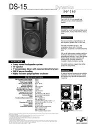
In addition to the amazing menu of processing available, the ZonePro units also afford you the<br />
luxury of utilizing dbx Zone-Controller series wall-mounted control panels that will allow you<br />
to remotely control various parameters of the unit. The ZC-1 and ZC-6 offer remote programmable<br />
Volume control to any installation using the ZonePro units. The ZC-2 provides programmable<br />
Volume and Mute control. The ZC-3 and ZC-4 allow Source selection, Scene selection<br />
or Page steering. ZC-FIRE provides an interface for fire safety systems. The ZC-7 remote<br />
offers page steering from a programmable push button interface. The ZC-8 provides a single<br />
panel with both push button volume control and source or scene selection. Up to 12 Zone<br />
Controllers can be used with a single ZonePro, and can either be wired in series or parallel.<br />
The ZC-BOB was created to accommodate “home-run” or parallel wiring to the unit. With a<br />
maximum length of 1,000 ft., the Zone Controllers offer a simple way to create a simple yet elegant<br />
solution to many installation applications.<br />
ZC-BOB ZC-1 ZC-2 ZC-3<br />
ZC-4<br />
A<br />
B<br />
VOLUME<br />
C<br />
D<br />
ZC-6<br />
ZC-7<br />
ZC-Fire<br />
ZC-6<br />
ZC-7<br />
ZC-8<br />
0.2 - Service Contact Info<br />
If you require technical support, contact dbx Customer Service. Be prepared to accurately<br />
describe the problem. Know the serial number of your unit - this is printed on a sticker attached<br />
to the top panel. If you have not already taken the time to fill out your warranty registration<br />
card and send it in, please do so now.<br />
Before you return a product to the factory for service, we recommend you refer to the manual.<br />
Make sure you have correctly followed installation steps and operation procedures. If you<br />
are still unable to solve a problem, contact our Customer Service Department at (801) 568-7660<br />
for consultation. If you need to return a product to the factory for service, you MUST contact<br />
Customer Service to obtain a Return Authorization Number.<br />
No returned products will be accepted at the factory without a Return Authorization Number.<br />
ZonePro User <strong>Manual</strong><br />
iii
Introduction<br />
ZonePro <br />
0.3 - Warranty<br />
Please refer to the Warranty information on the following page, which extends to the first enduser.<br />
After expiration of the warranty, a reasonable charge will be made for parts, labor, and<br />
packing if you choose to use the factory service facility. In all cases, you are responsible for<br />
transportation charges to the factory. dbx will pay return shipping if the unit is still under warranty.<br />
Use the original packing material if it is available. Mark the package with the name of the shipper<br />
and with these words in red: DELICATE INSTRUMENT, FRAGILE! Insure the package properly.<br />
Ship prepaid, not collect. Do not ship parcel post.<br />
This warranty is valid only for the original purchaser and only in the United States.<br />
1. The warranty registration card that accompanies this product must be mailed within 30 days<br />
after purchase date to validate this warranty. Proof-of-purchase is considered to be the burden<br />
of the consumer.<br />
2. dbx warrants this product, when bought and used solely within the U.S., to be free from<br />
defects in materials and workmanship under normal use and service.<br />
3. dbx liability under this warranty is limited to repairing or, at our discretion, replacing defective<br />
materials that show evidence of defect, provided the product is returned to dbx WITH<br />
RETURN AUTHORIZATION from the factory, where all parts and labor will be covered up to<br />
a period of two years. A Return Authorization number must be obtained from dbx by telephone.<br />
The company shall not be liable for any consequential damage as a result of the product's<br />
use in any circuit or assembly.<br />
4. dbx reserves the right to make changes in design or make additions to or improvements upon<br />
this product without incurring any obligation to install the same additions or improvements<br />
on products previously manufactured.<br />
5. The foregoing is in lieu of all other warranties, expressed or implied, and dbx neither assumes<br />
nor authorizes any person to assume on its behalf any obligation or liability in connection<br />
with the sale of this product. In no event shall dbx or its dealers be liable for special or consequential<br />
damages or from any delay in the performance of this warranty due to causes<br />
beyond their control.<br />
iv<br />
ZonePro User <strong>Manual</strong><br />
®
ZonePro <br />
Section 1<br />
Getting Started<br />
®
Section 1<br />
Getting Started<br />
ZonePro <br />
1.1 - Rear Panel (640 and 641)<br />
1 2 3 4 5 6 7 8 9 10<br />
1. IEC Power Cord Receptacle<br />
The ZonePro 640/641 comes with a power supply that will accept voltages ranging from 100V-<br />
120V at frequencies from 50Hz-60Hz. An IEC cord is included. EU version accepts 220V-240V<br />
at frequencies from 50Hz-60Hz.<br />
2. PC Connection<br />
This DB-9 connection is used to communicate to the PC GUI and uses RS-232 protocol. This<br />
connection requires a Null Modem cable and one is included with the ZonePro unit.<br />
3. Zone Control Inputs 1-12 (RJ-45 connector type)<br />
This input connection is used to send information and power to the ZC wall controllers.<br />
4. Outputs Channels 1-4<br />
The output section of the ZonePro offers four electronically balanced Euroblock connectors.<br />
5. Input Link Buss (RJ-45 connector type)<br />
The ZonePro offers an input buss that duplicates inputs from one unit to the next for applications<br />
requiring more than four output zones.<br />
6. Input Source Channels 1-4<br />
The input section of the ZonePro offers four mono-summing unbalanced RCA connectors.<br />
7. Line/Mic Selector<br />
This switch is used to select either a line or microphone input.<br />
8. Signal/Clip LED<br />
This LED is used to indicate microphone signal input or clip.<br />
9. Mic Gain Control<br />
This knob is used to set the input gain for the microphone input.<br />
10. Mic/Line Inputs 1-2<br />
The input section of the ZonePro provides two Euroblock connectors for mic/line inputs.<br />
2<br />
ZonePro User <strong>Manual</strong><br />
®
®<br />
Getting Started Section 1<br />
1.2 - Front Panel (640)<br />
1 2 3 4 5 6 7<br />
<br />
1.3 - Front Panel (641)<br />
1 2<br />
ZonePro<br />
ZonePro User <strong>Manual</strong> 3<br />
1. LCD Display<br />
The backlit LCD display of the ZonePro 640 provides the end-user with all the necessary controls<br />
including source selection, page steering, zone volume and mute.<br />
2. Parameter Select 1-3<br />
These three buttons (when pressed) are used in conjunction with the Data Wheel to select<br />
and edit parameters.<br />
3. Data Wheel<br />
The Data Wheel is used to edit parameter values.<br />
4. Page Buttons 1-2<br />
The Page buttons are used to adjust the page signal path and can be used to steer paging to<br />
selected zones.<br />
5. Zone Select<br />
These buttons are used to select output zones for front panel control.<br />
6. Output Meters<br />
The ZonePro 640 provides the user with four independent six-segment Lightpipe output meters<br />
that range from -30 to +20 dBu. These meters monitor the signal level directly before the D/A<br />
converter.<br />
7.Threshold Meters<br />
The threshold meters indicate that the threshold level has been exceeded within the output<br />
Compressor, Auto Gain Control, or Limiter sections, and gain reduction may be taking place<br />
within the specific output channel.<br />
1. PC Connection<br />
This DB-9 connection is used to communicate to the PC via RS-232 protocol.<br />
2. Power LED<br />
This LED (when lighted), indicates that the ZonePro 641 is currently powered.
Section 1<br />
Getting Started<br />
ZonePro <br />
1. 4 - Connections<br />
Example Setup<br />
When setting up the ZonePro units, make connections as follows:<br />
• Always make connections prior to applying power to the unit.<br />
• Connect the outputs from the sending devices (mixer, microphone, CD, DVD player or<br />
satellite, etc..) to either of four RCA, or two Euroblock input connectors.<br />
• Make output connections from the Euroblock connectors to the<br />
input of the selected power amps or powered speakers.<br />
• It is recommended that the power amps are turned off prior to cycling power to the<br />
ZonePro. Always make sure that your power amps are the last item turned on and the first<br />
turned off. Once all of the connections have been made and the unit is powered up, you<br />
can navigate through the entire signal path of the ZonePro from the included GUI.<br />
1.5 - PC GUI Installation<br />
Minimum System Requirements<br />
1 GHz processor<br />
Windows 2000 or XP<br />
128 meg RAM<br />
Recommended screen resolution:<br />
1024 x 768 pixels or higher<br />
Installation<br />
• Install the ZonePro GUI software from either the dbx website at www.dbxpro.com or from<br />
the included CD ROM onto your computer.<br />
• Once the software setup is downloaded, double click on the file named: ZonePro setup.<br />
• The application will proceed to prompt you for the installation location.<br />
• Once the software installation has been completed, it is recommended that you restart your<br />
computer.<br />
Note:You must disable virus protection software during the installation of ZonePro Designer.<br />
4<br />
ZonePro User <strong>Manual</strong><br />
®
ZonePro <br />
Section 2<br />
SOFTWARE<br />
OPERATION<br />
®
Section 2<br />
Software Operation<br />
ZonePro <br />
2. 1 - ZonePro Philosophy<br />
For your convenience, all the configuration and editing features of the ZonePro 640 and 641<br />
are performed via the included Zone Pro GUI. This section has been created to act as a tutorial<br />
for performing various editing aspects of the unit.<br />
The philosophy of the ZonePro 640 and 641 is built around the concept the concept of a configuration,<br />
a scene and a device file.<br />
Configuration<br />
The configuration includes all of the processing blocks, the I/O configuration, and the zone<br />
controllers. The configuration is set up by going through the Configuration Wizard. The<br />
ZonePro device can only have one configuration, so all configuration changes must be completed<br />
before you start storing scenes. For more information on the configuration see<br />
Configuration Wizard in section 3.<br />
Scenes<br />
A scene consists of the parameters for all the modules and the assignment of zone controllers<br />
to a zone. The ZonePro products allow switching of scenes from the Real Time Clock, or from<br />
a ZC zone controller. Up to 50 scenes can be stored in the ZonePro unit. For more information<br />
on scenes see section 3.<br />
Device<br />
The configuration, scenes, and schedule information can all be stored off to a device file or .zpd<br />
(ZonePro device). Storing a device file to the computer and then recalling it into another<br />
ZonePro unit allows for exact duplication of a system in a single file download.<br />
2. 2 - Views<br />
There are three different views within the ZonePro Designer GUI; Venue view, Program screen,<br />
and Module view. Venue view From the Venue View you can add or delete devices and configure<br />
your network including selecting your COM port. Double clicking on a unit icon in the<br />
Venue view takes you to the Program screen. Program screen provides you with a graphic<br />
representation of the configuration of the individual ZonePro unit, including all the processing<br />
modules and their positions in the signal path. The program screen also offers access to meters,<br />
scene storing and loading, the Wizard functions, and file storing. Double clicking on the processing<br />
modules take you to the Module view. Module view (also called edit screen) provides<br />
access to the processing parameters. Editing of parameters is done in Module view.<br />
2. 3 - Connections<br />
Once the software has been loaded and the ZonePro unit is connected via the included Null<br />
Modem cable, run the Graphic User Interface (GUI) by double clicking on the application icon.<br />
You will see the ZonePro Designer window open with an icon of the ZonePro unit. Double<br />
clicking on the unit will open the unit to the program screen where you will be able to see the<br />
processing modules and the configuration. If the computer cannot connect to the ZonePro<br />
device, check the COM port assignment under Network Properties in the Venue View, and make<br />
sure that you are connecting to the correct COM port.<br />
6<br />
ZonePro User <strong>Manual</strong><br />
®
®<br />
ZonePro 7<br />
Software Operation Section 2<br />
The ZonePro Designer GUI provides a mechanism for creating scenes and device files while<br />
not physically connected to a ZonePro unit. To work off-line, open the GUI, select DEVICE<br />
then select ADD. At this point you will be prompted to choose a 640 or 641. Once the unit<br />
has been inserted into GUI you can proceed to configure, edit, create scenes, and save<br />
ZonePro device files.<br />
Configuration of the ZonePro is done from the Configuration Wizard and allows setup of the<br />
inputs and outputs along with selection of their processing modules, zone controller setup, signal<br />
routing, and front panel setup. For a detailed operation description see "The Wizard" section<br />
3.1.<br />
2. 4 - Online/Offline<br />
2. 5 - Configuration<br />
To edit a processing module, double click on that module. Adjust the module to taste; make<br />
sure that the module is engaged. This is usually indicated by the module ON button in the<br />
upper left corner of the parameter section. Although process editing is done in real-time, the<br />
changes can either be discarded or accepted by selecting the OK or CANCEL button. The<br />
following screen shot shows the example of the Output Delay module. Parameters can be<br />
copied and pasted between like modules in the ZonePro GUI. From the program screen either<br />
right click on the module and select Copy, or select Edit and Copy from the Menu Bar to Copy<br />
parameters. To past either right click and select Paste, or click on Edit Paste from the Menu<br />
Bar.<br />
2. 6 - Editing<br />
ZonePro User <strong>Manual</strong>
Section 2<br />
Software Operation<br />
ZonePro <br />
2. 7 - Saving and Recalling Scenes<br />
As previously stated, scenes include parameter data and zone controller assignment. Multiple<br />
scenes can be saved and recalled by either clicking on the Scene tab of the Menu bar or by<br />
using the Store Scene and Recall Scene buttons.<br />
In use, multiple scenes can be recalled from either a zone controller or the Real Time Clock.<br />
The time in the Real Time Clock is set when entering the GUI, or it can be set using the Edit<br />
tab on the Menu bar and selecting time.<br />
2. 8 - Meters<br />
The input and output level meters can be turned off by clicking on the Meter button. Turning<br />
the meters off will help speed the communication and processing of slower computer systems.<br />
The ZonePro Designer GUI defaults with the meters turned on.<br />
2. 9 - Saving Files<br />
The device file provides a way to store off the entire ZonePro unit to a computer, which<br />
includes the configuration, scenes, and schedule information. To save a ZonePro device file,<br />
select File then Save from the Menu bar.<br />
8<br />
ZonePro User <strong>Manual</strong><br />
®
ZonePro <br />
Section 3<br />
Setup<br />
SYSTEM<br />
SETUP<br />
®
Section 3<br />
3.1 - Overview<br />
System Setup<br />
ZonePro <br />
The System Setup section of the ZonePro manual will provide the user with detailed instruction<br />
for Configuration of the ZonePro unit and any Zone Controllers that may be used with it.<br />
The following sub-sections will provide you with detailed information regarding the various<br />
setup functions. Typical setup procedure of a ZonePro unit is as follows:<br />
Step 1, Configuration Wizard - Use the Configuration Wizard to create the system configuration<br />
including I/O setup and naming along with DSP selection. The Configuration Wizard<br />
also provides Zone controller setup, routing setup and front panel setup for the 640.<br />
Step 2, Parameter Editing - Double clicking on the various modules allows editing of parameters<br />
to adjust settings for individual installations or scenes.<br />
Step 3, Scene Storing - Whether using a single scene or many, storing the scene is important<br />
to make sure that all parameter changes are saved. If just one scene is desired save this as<br />
the Default Scene.<br />
Step 4, Scene Wizard - If multiple scenes are desired with routing or zone controller assignment<br />
changes, use the Scene Wizard to make those changes. Repeat Steps 2 and 3.<br />
Step 5, Schedule Wizard - If multiple scenes are to be loaded using the Schedule function,<br />
setup the Schedule using the Schedule Wizard for each scene change. Make sure the clock is<br />
correct by clicking on Edit then Time from the Menu Bar.<br />
Step 6, File Save - It is recommended that you save off a copy of your ZonePro device file<br />
using the File Save on the Menu bar. This file is a back-up and might come in handy for<br />
similar future installations.<br />
3.2 - Configuration Wizard<br />
The Wizard function is used to configure the ZonePro processing modules, Zone Controllers<br />
and Front Panel. It provides a menu based decision tree to speed setup. This sub-section will<br />
walk you through each page of the Wizard function.<br />
• From the Program Screen view of the setup, the display will appear something like this:<br />
• Select the Wizard pull down from the menu bar and then select the option labeled<br />
Configuration Wizard. Once selected, a window will appear as follows:<br />
10<br />
ZonePro User <strong>Manual</strong><br />
®
®<br />
System Setup Section 3<br />
3.2.1 Input Setup<br />
• This page is the Input Setup Page page and allows naming of inputs, input configuration<br />
(mono or stereo), and selection of the two mic/line DSP modules. Once you have named<br />
your inputs and selected insert modules, click on the Next Page button and the display will<br />
appear as follows:<br />
ZonePro 11<br />
3.2.2 Output Setup<br />
• This page is the Output Setup Page and allows naming of the outputs, zone configuration,<br />
and selection of the Dynamics DSP module. The outputs can be configured as mono, or<br />
stereo either with or without a subwoofer. Once you have performed all of your output<br />
setup modifications, click on the Next Page button and the display will appear as follows:<br />
ZonePro User <strong>Manual</strong>
Section 3<br />
System Setup<br />
ZonePro <br />
3.2.3 ZC Panel Configuration<br />
The ZC Panel Configuration Page allows setup of wall-mounted Zone Controllers to be used<br />
with the ZonePro unit.<br />
ID #s - The ID numbers on the left side of the window correspond to the identification number<br />
set using the DIP switches on the individual zone controllers. ID 1-6 are connected to one<br />
of the ZC inputs on the rear panel and ID 7-12 are connected to the other input. For ID 7-12<br />
add 6 to the ID # selected on the back of the ZC. For example, if I am connecting to input 7-<br />
12 and I am connecting a ZC with ID #3 selected this would be ID #9.<br />
Names - The zone controllers can be named to eliminate confusion in later menus.<br />
Since several zone controllers have multiple functions examples of each function will be shown:<br />
Scenes - To change scenes a ZC-3 or ZC-4 must be used in the ID #1 position. This zone controller<br />
must have the scene check box checked. Select the desired scenes from the list of scenes<br />
on the right hand side of the window and associate it with the selector position A, B, C, D on<br />
a ZC-3 or switch position 1-16 on a ZC-4 (see ZC-4 switch positions within the Appendix).<br />
Fire - The ZC-FIRE is a special case of scene selection. A ZC-FIRE can only be assigned to ID<br />
#2. Select whether the ZC-FIRE should be activated when taken high or low. Select to either<br />
Mute all outputs, or select the desired scene to be loaded.<br />
Volume - A ZC-1, ZC-2, ZC-6, or ZC-8 can be used to adjust volume. Select the desired ZC<br />
type, and make sure it has the correct ID number. Set the maximum and minimum values for<br />
this zone controller. As a default, all volume zone controllers can provide up to +20dB gain<br />
boost and can cut to -Inf to mute.<br />
Source Selection - A ZC-3, ZC-4, or ZC-8 can be used to provide source selection. Select the<br />
desired ZC type and make sure it has the correct ID number. for a ZC-3 or ZC-8, for each switch<br />
position A-D select the corresponding source. For a ZC-4, select the switch position 1-16 and<br />
choose the corresponding input source (see ZC-4 switch positions within the Appendix).<br />
Page Routing - To dynamically route or assign pages a ZC-3, ZC-4 or ZC-7 can be used. Select<br />
the desired ZC type, and make sure it has the correct ID number. For a ZC-3 only four zones<br />
or groups of zones can be switched between. Select which microphone is to be dynamically<br />
routed with this zone controller; for each position of the ZC-3 select the zones that are to to be<br />
paged by checking in the boxes for each zone output. A ZC-4 can switch between 16 zones<br />
or groups of zones. First choose which of the two microphones is to be routed with this zone<br />
12<br />
ZonePro <br />
User <strong>Manual</strong><br />
®
®<br />
ZonePro 13<br />
System Setup Section 3<br />
controller, then select the desired zones with each of the 16 switch positions. Like a ZC-3, the<br />
ZC-7 only has four positions so it will only support up to four zones or groups of zones, but it<br />
does have momentary switches that can be used in a push to call fashion, where each switch<br />
must be pushed and held to route the page to that zone or group of zones. First, select the<br />
microphone to be steered, then for each switch position choose the zones or groups of zones<br />
that are to be paged. Once you have performed all your zone controller configurations, click<br />
NEXT to move to the Routing Configuration.<br />
3.2.4 Routing Setup<br />
• The Routing Setup Page allows selection of the main Source, the Priority override source,<br />
the Page source, and the output level for each of the output zones. If Zone Controllers are<br />
used for either source selection or level control, these should be selected in the Source or<br />
Level pulldown menu. If zone controllers are being used for Page Steering select None in<br />
the Page menu for those outputs unless a microphone is always paging to that zone in<br />
addition to the page steering.<br />
ZonePro User <strong>Manual</strong>
Section 3<br />
System Setup<br />
ZonePro <br />
3.2.5 Front Panel Setup<br />
• The Front Panel Setup Page allows selection of which controls will be available to the enduser<br />
of the 640 unit. If Zone Controllers are being used for page steering, source, or volume<br />
control of an output zone these parameters will not be available from the front panel.<br />
• Once all the Wizard pages have been completed the configuration is ready to be loaded,<br />
this is accomplished by selecting finish. You will now be returned to the normal editing<br />
mode of the ZonePro GUI.<br />
3.3 - Scene Wizard<br />
The Scene Wizard function is used to setup the various scenes that may be required within the<br />
installation. The Scene Wizard menu offers a single page window that provides a menu based<br />
decision tree to speed setup. This sub-section will walk you through the options of the Scene<br />
Wizard function.<br />
• From the Program Screen view of the setup, the display will appear something like this:<br />
• Select the Wizard pull down from the menu bar and then select the option labeled Scene<br />
Wizard. Once selected, a window will appear as follows:<br />
14<br />
ZonePro User <strong>Manual</strong><br />
®
®<br />
ZonePro 15<br />
System Setup Section 3<br />
The Schedule Wizard provides for pre-determined scene changes corresponding to the time of<br />
day and/or day of week. For example installations such as restaurants often require volume<br />
increases during peak hours of operation. This sub-section will walk you through setting up<br />
the Schedule Wizard.<br />
• From the Unit view of the setup, the display will appear something like this:<br />
3.4 - Schedule Wizard<br />
• Select the Wizard pull down from the menu bar and then select the option labeled<br />
Scheduler Wizard. Once selected, a window will appear as follows:<br />
• At this point you can create a schedule for each day of the week, by recalling scenes at<br />
any time with up to 1 minute resolution. Up to 24 scenes can be recalled per day. Once<br />
all changes have been made, select Ok or Cancel and the window will be closed.<br />
ZonePro User <strong>Manual</strong>
Section 3<br />
System Setup<br />
ZonePro <br />
16<br />
ZonePro User <strong>Manual</strong><br />
®
ZonePro <br />
Section 4<br />
Detailed Parameters<br />
DETAILED<br />
PARAMETERS<br />
®
Section 4<br />
Detailed Parameters<br />
ZonePro <br />
4.1 - Input<br />
The following section will provide you with a module block representation for each effect, as<br />
well as descriptions and explanations of all parameters within the ZonePro.<br />
The signal routing begins at the INPUT block of the ZonePro.<br />
Gain Level -Inf to 20dB<br />
Adjusts the input level.<br />
HP Frequency Off, 14.96Hz to 118.85Hz (Mic Inputs Only)<br />
Adjusts the input High Pass cutoff frequency.<br />
4.2 - Input Parametric EQ<br />
The ZonePro units offer Pre-crossover parametric sections on each input, and may be configured<br />
as a single or linkable 2-band (RCA inputs only) or 4-Band PEQ (Mic inputs only).<br />
EQ On/Off<br />
Turns the PEQ on and off.<br />
Type Low Shelf, HighShelf, Low/High Shelf and Bell<br />
The Type selector allows you to select either a Low, High, Low/High shelf or Bell EQ curve.<br />
18<br />
ZonePro User <strong>Manual</strong><br />
®
®<br />
Flat /Restore<br />
These buttons either flatten (Flat) or restore (Restore) all bands to their original settings.<br />
Band (1-4) Frequency 20Hz to 20kHz (Low Shelf)<br />
Selects the frequency of the EQ.<br />
Q (1-4) 0.105 to 16.0<br />
Selects the Q or the Bell parametric EQ.<br />
Slope (Type: High and/or Low Shelf Selected) 3-12dB/Octave<br />
Sets the slope of the High and/or low shelf parametric EQ.<br />
Detailed Parameters Section 4<br />
ZonePro 4.3 - AGC ( Insert and DYN Module)<br />
This is done by selecting a<br />
The AGC keeps the signal within the Window about<br />
The maximum gain that can be applied to the<br />
When the input signal falls below the Threshold the<br />
This prevents the AGC from adding gain when<br />
High level peak signals are<br />
The AGC Threshold meters show<br />
The T (yellow) indicates the signal is within the<br />
When the Threshold meter is off<br />
19<br />
Level (1-4) -12 to 12 dB<br />
Sets the overall level of the selected parametric EQ.<br />
The AGC is used to keep the average level of a signal constant.<br />
desired Target output level and Window.<br />
the selected Target by slowly adjusting the gain.<br />
signal is selected by the Gain parameter.<br />
AGC releases the gain and returns to unity.<br />
there is no signal present and raising the system noise floor.<br />
reduced by a fast limiter to prevent distortion by clipping.<br />
what region of the AGC the input signal is in.<br />
Window. A + (red) indicates the signal is above the target window. A – (green) indicates the<br />
AGC is adding adding Gain and is at or below the window.<br />
the signal is below the Threshold. The AGC module also includes a dedicated Limiter.<br />
AGC On/Off<br />
Turns the AGC module On and Off.<br />
®<br />
ZonePro User <strong>Manual</strong>
Section 4<br />
Detailed Parameters<br />
ZonePro <br />
Target -20 to 20 dB<br />
The Target parameter defines where you would like the average level of the AGC output to be.<br />
If the average level of the signal rises above the Target the gain will be reduced. For signals<br />
with an average level below the Target the gain will be increased.<br />
Gain 1 to 20dB<br />
This adjusts the maximum amount of gain that can be added by the AGC.<br />
Window 1 to 10dB<br />
This adjusts the amount of variation in the output<br />
Low Threshold -60 to -30dB<br />
The Low Threshold sets a lower limit to the AGC.<br />
low level signals or noise.<br />
This prevents the AGC from adding gain to<br />
Attack 0.20 to 5 Seconds<br />
This adjusts how fast the AGC will increase gain.<br />
Release 30.0 to 1 dB/Second<br />
This adjusts how fast the AGC will reduce gain.<br />
AGC Limiter Threshold -40 to +20dBu<br />
The AGC is designed to add or remove gain slowly to maintain an average signal level.<br />
Because of its slow nature a fast Limiter has been added to protect speakers from sudden transients.<br />
The Limiter threshold can be set from the top of the AGC Window up to +20dBu.<br />
AGC Limiter Attack .01 to 200 m Sec<br />
This is the speed at which the limiter starts to compress the signal once it has crossed the<br />
threshold.<br />
AGC Limiter Release 360 to 5 dB / Sec<br />
Just like the release time on the compressor, the limiter's release time controls how fast the limiter<br />
releases from gain reduction after the signal drops below the threshold.<br />
4.4 - Notch Filters (Insert Module)<br />
The notch filter is the perfect tool for dropping out undesirable frequencies that may appear in<br />
the input signal.<br />
20<br />
ZonePro User <strong>Manual</strong><br />
®
®<br />
Detailed Parameters Section 4<br />
ZonePro ZonePro User <strong>Manual</strong><br />
21<br />
Notch On/Off<br />
Turns the notch filters on and off.<br />
Frequency (1 to 6) 20 to 20K<br />
Selects the desired notch filter frequency of the selected notch filter.<br />
Q 16 to 128<br />
Selects the Q of the selected notch filter.<br />
Level -36 to 6 dB<br />
Sets the level of the selected notch filter. Set to +6dB to help find unwanted feedback, then set<br />
to -3dB to -36dB to remove.<br />
4.5 - Compressor (Insert and DYN Module)<br />
The ZonePro also offers a dedicated compression module. The Compressor is the perfect tool<br />
for tightening uneven signal sources such as vocals and guitars. The parameters for the<br />
Compressor are as follows.
Section 4<br />
Detailed Parameters<br />
ZonePro <br />
Compressor On/Off<br />
Turns the Compressor module on and off.<br />
OverEasy Off to 10<br />
OverEasy is a soft-knee smoothing function that occurs about the compression threshold.<br />
OverEasy off is considered hard knee; the higher the OverEasy the greater the smoothing.<br />
Threshold -40 to +20dBu<br />
Threshold is the signal level at which the unit starts to compress the signal. If the level is set to<br />
-10 dBu, than any signal larger than -10 dBu is compressed while any signal that has a level<br />
that is lower than -10dBu is left at the same signal level. For most signals the most natural compression<br />
is achieved when most of the signal content remains just below the threshold and only<br />
the peaks cross the threshold.<br />
Ratio 1.0 to Inf:1<br />
Ratio is the amount the unit reduces the signal level of the sound that is above the threshold.<br />
A 2:1 ratio means that if the incoming signal is 2dB over the threshold the unit will compress<br />
the signal, and outputs a signal that only goes 1dB over the threshold. For light compression<br />
choose a lower ratio, while a heavy compression requires a higher ratio. A setting of Inf:1 makes<br />
the compressor act as a limiter.<br />
Gain -20 to +20 dB<br />
This parameter is used to compensate for the gain lost during compression. By using heavy<br />
compression on a signal and then boosting the signal with the output gain, the user can create<br />
a signal that sounds much louder than it actually is.<br />
22<br />
ZonePro User <strong>Manual</strong><br />
®
®<br />
ZonePro Auto On/Off<br />
When Auto Mode is on, the ZonePro automatically sets the Attack, Hold, and Release times<br />
for the signal. The auto mode constantly adjusts these parameters in real time for optimum performance<br />
from the unit. You will find that for most applications, not only is using the auto mode<br />
faster and easier but by letting the unit constantly tweak these parameters for you will result in<br />
a better end result.<br />
Attack 0.1 m Sec to 200 m Sec<br />
Attack is how fast the compressor starts to compress the signal after it passes the threshold. Fast<br />
attack is useful when dealing with lots of fast transients. The attack control is not active when<br />
in auto mode.<br />
Hold 0 to 500 m Sec<br />
Hold is the time the ZonePro remains in compression after the signal has dropped below the<br />
threshold. A longer hold time is useful in smoothing out the sound when compressing several<br />
fast peaks that are fairly close together in time. The hold control is not active while in auto<br />
mode.<br />
Release 360 dB / Sec to 5 dB / Sec<br />
Release is how fast the ZonePro comes out of compression. The release is in dB per second.<br />
For example, if release is set to 5 dB /sec, and the signal is at 10dB of gain reduction, the release<br />
time is 2 seconds. Having a release time that is either too fast or too slow for the signal can<br />
result in audible artifacts called pumping or breathing. This can cause volume drops in your signal<br />
that may not be desired. The release control is not active while in auto mode.<br />
4.6 - Noise Gate (Insert Module)<br />
ZonePro User <strong>Manual</strong><br />
23<br />
Detailed Parameters Section 4<br />
Gate On/Off<br />
Turns the Gate on and off.
Section 4<br />
Detailed Parameters<br />
ZonePro <br />
Threshold -50 to 20 dBu<br />
The threshold is the level at which the gate opens. Anything above the threshold passes, while<br />
signal that is lower than the threshold is attenuated. Beware, setting the threshold to high can<br />
cut off the tail end of signals as they fade out (the sustain of a guitar note, a held piano chord,<br />
a reverb tail, etc.).<br />
Ratio 1:1.0 to 1:15<br />
This is where you decide how much downward expansion you want. This ratio works opposite<br />
from that of the compressor or limiter. If a ratio of 1:4 is selected, a signal that is 1dB below<br />
the threshold will be reduced in gain so that it becomes 4dB below the threshold.<br />
Attack 0.1 to 200 m Sec<br />
As the signal reaches the threshold area, the Attack control sets the speed at which the gate<br />
opens. Use very fast attack times to catch the fronts of transient signals.<br />
Hold 0 to 500 m Sec<br />
The Hold control sets the amount of time the gate is held open after the signal passes below<br />
the threshold point.<br />
Release 360 to 5 dB<br />
Release sets the speed at which the gate “closes” or attenuates when the end of the Hold time<br />
is reached.<br />
Max Attenuation 0 to Inf. dB<br />
This sets the maximum amount of attenuation for the gate.<br />
4.7 - De-Esser (Insert Module)<br />
The ZonePro offers a de-Esser module. This De-esser effect is ideal for removing unwanted<br />
vocal sibilance. These parameters are user adjustable on all programs and are as follows:<br />
24<br />
De-Esser On/Off<br />
Turns the De-Esser on or off.<br />
ZonePro User <strong>Manual</strong><br />
®
®<br />
ZonePro Freq 800 Hz to 8.00 kHz<br />
This is the center frequency the De-Esser uses when in Band Pass mode or the corner frequency<br />
used when in High Pass mode.<br />
Amount 0 to 100%<br />
This controls the amount of De-Essing. The amount control is very much like a combination<br />
threshold / ratio control. A higher amount applies more De-Essing to the signal.<br />
Type HP or BP<br />
Selects the type of filter used by the De-Esser.<br />
Width<br />
Sets the Q of the Band Pass Filter.<br />
4.8 - AFS (Insert Module)<br />
The ZonePro offers the exclusive patent pending AFS (Advanced Feedback Suppression)<br />
feedback elimination module. Feedback is caused when a microphonic signal such as a guitar<br />
pickup or microphone is reproduced by an amplification and is repeatedly picked up in phase.<br />
The AFS module of the ZonePro allows the user to optimize the elimination of feedback.<br />
With the AFS algorithm active the ZonePro removes only the feedback frequencies without<br />
affecting the remaining audio spectrum.<br />
ZonePro User <strong>Manual</strong><br />
25<br />
Detailed Parameters Section 4<br />
AFS On/Off<br />
Turns the AFS module on and off. If AFS is Off, the filters are bypassed, and the algorithm is<br />
halted (the filters are not updated). If AFS is On, the filters are active, and the they are updated<br />
according to the current selected mode (Fixed or Live).<br />
Clear Live and ClearAll<br />
These buttons (when selected) clear the filters. If Clear Live is selected, only the live filters are<br />
reset. If Clear All is selected, then all of the filters are reset.
Section 4<br />
Detailed Parameters<br />
ZonePro <br />
Mode - Live or Fixed<br />
When the mode is Fixed, the algorithm updates only the fixed filters. When the mode is Live,<br />
the algorithm updates only the live filters. In FIXED mode, the filters are stored with the program<br />
at that frequency until cleared by the user. Fixed mode is used during setup to set filters<br />
at frequencies that are most likely to feedback. In LIVE mode, the live filters automatically<br />
detect and remove feedback during the performance. When all of the live filters have been<br />
used, they begin to round robin. Essentially this means that the first filter set is moved where<br />
a new feedback is detected and notched out. This mode is useful because feedback frequencies<br />
may change as the microphone is moved, and/or as the characteristics of the venue change.<br />
Note- Only the fixed filter settings will be stored with the program.<br />
Type - Speech, Low Music, Medium Music and High Music<br />
Type allows the AFS algorithm to be customized for the application. The Values correspond<br />
to different Q and sensitivity settings. These types pertain to the Q, sensitivity, and algorithm<br />
type. Values are; Speech (Bandwidth = 1/5 octave and Q=7.25) Music Low (Bandwidth = 1/10<br />
octave and Q=14.5) Music Medium (Bandwidth = 1/20 octave and Q=29) Music High<br />
(Bandwidth = 1/80 octave and Q=116). Note: To guarantee that feedback is suppressed at<br />
lower frequencies, the AFS may place wider notch filters at these lower frequencies (below<br />
700 Hz).<br />
Total Number of Filters 1-12<br />
This parameter selects the number of filters being used<br />
Number Fixed - 0-12<br />
This parameter sets the number of Fixed AFS filters. This also sets the number of Live filters as<br />
the Total number of filters - number of Fixed Filters = number of Live Filters.<br />
Live Filter Lift (On/Off)<br />
This parameter turns the Live Filter Lift on and off.<br />
Lift After - 5 sec to 60 min<br />
This parameter allows the user to setup the box so that the Live filters will automatically be<br />
removed after a set time (as indicated by the "Lift After" parameter). It ranges from 5 seconds<br />
to 60 minutes. This feature is useful if the microphone being used is moved or the characteristics<br />
of the venue change over time. This feature removes unnecessary filters from the spectrum<br />
to increase sonic quality.<br />
Detector Highpass Off, 11.7 - 410.1Hz<br />
This parameter sets a highpass filter in the path of the AFS detector. There may be occasions<br />
where the AFS algorithm is removing too much low end because it is being triggered by<br />
Synthesizer or Bass notes that are not really feedback. This parameter provides a mechanism<br />
to make the AFS algorithm less sensitive to low frequency thereby setting fewer filters in the<br />
bass region.<br />
Sensitivity -20-+20dB<br />
The AFS algorithm is very effective when the audio has a nominal level of 0 dBu, however if<br />
the audio is too low in level the AFS algorithm may not catch feedback as quickly as possible.<br />
By increasing or decreasing the sensitivity you can adjust for audio that is either too loud or too<br />
soft and help the AFS function properly.<br />
26<br />
ZonePro User <strong>Manual</strong><br />
®
®<br />
Detailed Parameters Section 4<br />
The Router module is the heart of the ZonePro device and allows for a primary source, a priority<br />
override sources and a paging source, where the paging source has the highest priority.<br />
Both priority override and page have duckers that allow them to duck the previous sources.<br />
4.9 - Router<br />
ZonePro ZonePro User <strong>Manual</strong><br />
27<br />
Source Select<br />
This parameter allows the user to select the input source for the zone.<br />
Priority Select<br />
This parameter allows the user to select which input will override the primary source signal..<br />
Priority Level -Inf to 20dB<br />
Adjusts the output level of the selected Priority input signal.<br />
Page Select<br />
This parameter allows the user to select which Paging input will override the source signal.<br />
Page Level -Inf to 20dB<br />
Adjusts the output level of the selected Paging input signal.<br />
Master Level -Inf to 20dB<br />
This parameter adjusts the output level of of the Zone.<br />
Master mute<br />
When selected, the the signal will be muted for the Zone.<br />
The Router contains two Ducker modules for Priority and Page sources. The Priority Ducker<br />
attenuates the primary source and adds the Priority source. The Priority source is also gated<br />
using the same timing as the Priority Ducker. When the Priority source crosses the Priority<br />
Ducker Threshold the Ducker attenuates the Primary source by the Depth amount. At the same<br />
time the Priority Gate opens to allow the Priority source to be summed over the primary source.<br />
The Gate depth is –INF when closed to prevent adding noise to the primary source.
Section 4<br />
Detailed Parameters<br />
ZonePro <br />
The Page Ducker attenuates both the primary source and the Priority source if present. A Page<br />
source Gate can be added using the Mic/Line Insert 1 or 2.<br />
Threshold -40 to +20dBu<br />
Threshold is the level from the priority or page source at which the Ducker will attenuate the<br />
Router source.<br />
Depth Inf to 0dB<br />
This parameter sets the amount of Ducker attenuation.<br />
Attack 0.1 m Sec to 200 m Sec<br />
Attack is how quickly the signal is attenuated by the Ducker<br />
Hold 0.1 to 20.2 m Sec<br />
Hold time is the length of time before the Ducker releases.<br />
Release 0.0 to 10.0 dB/Sec<br />
Release is how quickly the attenuated signal returns to its nominal level.<br />
4.10 - Auto Warmth ®<br />
The ZonePro 640 and 640 offer the AutoWarmth® module on each output. AutoWarmth® is<br />
a patent pending process that compensates for naturally occurring bass frequency loss for low<br />
level signals. The Fletcher-Munson Equal Loudness curves show that the perception of low frequency<br />
signals decreases quickly with decreasing loudness. AutoWarmth® gradually boosts the<br />
low end in response to the overall loudness of the signal. The result is warm and balanced signal<br />
at low levels.<br />
28<br />
ZonePro User <strong>Manual</strong><br />
®
®<br />
ZonePro Auto Warmth On/Off<br />
This parameter is used to turn the Autowarmth module on and off.<br />
Threshold -40 to +20dBu<br />
The threshold sets the level where AutoWarmth® begins to work. Signals below the threshold<br />
are processed to increase the Bass response in proportion to the overall volume of the signal.<br />
Above the threshold there is no processing. The Threshold meter will light Green when the<br />
threshold has been crossed and AutoWarmth is active. To set the threshold, turn AutoWarmth®<br />
off and adjust the Master gain in the router to the desired listening level. Turn AutoWarmth®<br />
on and adjust the threshold until the threshold meter just turns off. Now as the volume decreases<br />
below the desired level the bass will gradually increase. Be careful when using<br />
AutoWarmth® followed by an AGC. The AGC can add gain when below the AutoWarmth®<br />
threshold resulting in overcompensated Bass.<br />
Amount 0.25:1 to 4.00:1<br />
The amount controls how much Bass is added. A setting of 1.00:1 compensates the signal as<br />
described by the Fletcher-Munson Equal Loudness curves. Higher settings (greater that 1.00)<br />
causes more bass. Lower setting result is less bass compensation.<br />
4.11 - Bandpass Filter/Crossover (BPF)<br />
ZonePro User <strong>Manual</strong><br />
29<br />
Detailed Parameters Section 4<br />
Highpass Out to 20kHz<br />
Adjusts the lowest frequency that the output will achieve.<br />
Lowpass Out to 20Hz<br />
Adjusts the highest frequency that the output will achieve.<br />
Gain -Inf to 20dB<br />
Sets the gain of the Crossover output.<br />
Low Pass and High Pass Slope - Butterworth (BW 6,12,18 and 24), Bessel<br />
(BS 6,12,18 and 24) and Linkwitz-Riley (LR 12 and 24)<br />
Selects the desired crossover slope type.
Section 4<br />
Detailed Parameters<br />
4.12 - Output Parametric EQ<br />
ZonePro <br />
The ZonePro units offer parametric EQ on all inputs. A 4-Band PEQ is available on the Mic/Line<br />
inputs while a 2-Band PEQ is available on the RCA line inputs.<br />
EQ On/Off<br />
Turns the PEQ on and off.<br />
Type Low Shelf, HighShelf, Low/High Shelf and Bell<br />
The Type selector allows you to select either a Low, High, Low/High shelf or Bell EQ curve.<br />
Flat /Restore<br />
These buttons either flatten (Flat) or restore (Restore) all bands to their original settings.<br />
Band (1-6) Frequency 20Hz to 20kHz (Low Shelf)<br />
Selects the frequency of the low pass shelf parametric EQ.<br />
Q (1-6) 0.105 to 16.0<br />
Q is adjustable from 0.105 to 16.000<br />
Slope (Type: High and/or Low Shelf Selected) 3-12dB/Octave<br />
Sets the slope of the High and/or low shelf parametric EQ.<br />
Level (1-6) -12 to 12 dB<br />
Sets the overall level of the selected parametric EQ frequency.<br />
4.13 - Output Dynamics<br />
The ZonePro units offer a dedicated output dynamics module which includes Compression,<br />
Limiting and Auto Gain Control. The Output Dynamics are located on each output channel and<br />
have been strategically placed for speaker and amplifier protection. Note: Compression parameters<br />
are explained in sub section 4.5, and AGC parameters are explained in sub section 4.3.<br />
30<br />
ZonePro User <strong>Manual</strong><br />
®
®<br />
Detailed Parameters Section 4<br />
ZonePro 31<br />
Limiter On/Off<br />
Turns the Limiter module on and off.<br />
OverEasy (O) Off to 10<br />
OverEasy is a soft-knee smoothing function that occurs about the limiting threshold. OverEasy<br />
off is considered hard knee; the higher the OverEasy, the greater the smoothing.<br />
Threshold -40 to +20dBu<br />
Threshold is the signal level at which the unit starts to limit the signal. If the level is set to -10<br />
dBu, any signal larger than -10 dBu is limited while any signal that has a level that is lower than<br />
-10dBu is left at the same signal level. Light limiting is where only the loudest parts of the signal<br />
go over the threshold. Very heavy limiting can be achieved by setting the threshold low<br />
enough that almost the entire signal content is over the threshold. For most signals, the most<br />
natural compression is achieved when most of the signal content remains just below the threshold<br />
and only the peaks cross the threshold.<br />
Auto On/Off<br />
When auto is turned on the ZonePro will continuously set the attack / hold / release controls itself.<br />
Attack .01 to 200 m Sec (per band or global)<br />
This is the speed at which the limiter starts to limit the signal once it has crossed the threshold.<br />
Hold 0 to 500 m Sec (per band or global)<br />
Hold is the time the limiter stays in gain reduction after the signal level has dropped below<br />
threshold. Hold is useful when you want the limiter to function for a period of time after it has<br />
been triggered. Be careful not to set the hold time too long as it will not release in time.<br />
Release 360 to 5 dB / Sec (per band or global)<br />
Just like the release time on the compressor, the limiter's release time controls how fast the limiter<br />
releases from gain reduction after the signal drops below the threshold. Set the release times<br />
longer for lower frequency bands and shorter for higher frequency bands.
Section 4<br />
Detailed Parameters<br />
ZonePro <br />
PeakstopPlus ® On/Off<br />
The first stage of PeakStopPlus is the Instantaneous Transient Clamp which clamps the signal<br />
with a soft logarithmic clamp function. This logarithmic function ensures that the signal will not<br />
exceed the level set by the PeakStopPlus OVERSHOOT control by more than the overshoot<br />
amount, and that it will not introduce harsh artifacts. The second stage is a unique program limiter<br />
featuring Intelligent Predictive Limiting. Its function is to monitor the input signal and<br />
intelligently predict the amount of gain reduction needed to keep the output signal below the<br />
ceiling set by the Instantaneous Transient Clamp.<br />
Overshoot 1-6<br />
This parameter sets the amount of overshoot for the Instantaneous Transient Clamp.<br />
4.14 Delay<br />
The parameters for the delay are as follows and are user adjustable:<br />
4.15 - Output<br />
Delay On/Off<br />
Turns the delay module on and off.<br />
Length<br />
Sets the amount of delay time. Maximum delay time is 650ms.<br />
Units Seconds, Feet or Meters<br />
Selects the unit of measurement for the delay.<br />
Polarity Normal or Invert<br />
This section is used to select either the Positive or Negative polarity.<br />
32<br />
ZonePro User <strong>Manual</strong><br />
®
ZonePro <br />
Section 5<br />
APPLICATION<br />
GUIDE<br />
®
SECTION 5<br />
5.1 - Retail Install<br />
Application Guide<br />
ZonePro <br />
34<br />
ZonePro User <strong>Manual</strong><br />
®
®<br />
Application Guide SECTION 5<br />
ZonePro 35<br />
Retail Application Notes<br />
1. The configuration is setup from the Wizard function and is used to select the main inputs to each zone except the<br />
sales floor where the ZCs are selected as the source and level.<br />
2. All paging is done from the phone page interface and can be steered to the sales floor, the stock room, and the<br />
office, but not the music on-hold. Page steering is done from the front panel of the ZonePro 640.<br />
3. The Zone Controllers are wired with CAT5 cable in series with the ZC-3 (Source Selection) as ID #1, and ZC-1<br />
(Volume) as ID #2, and are placed next to the cash register.<br />
4. EQ, Feedback Suppression and De-Essing are used on the phone page input to help improve intelligibility and<br />
reduce unwanted feedback in the system.<br />
5. The Bandpass Filters are used to reduce the out of band information being sent to the speakers so their efficiency can be maximized.<br />
6. EQ is used in all zones to make the system sound as good as possible.<br />
7. Auto Gain Control is being used on all output zones to maintain the signal level.<br />
ZonePro User <strong>Manual</strong>
SECTION 5<br />
Application Guide<br />
5.2 - Restaurant/Bar Install<br />
ZonePro <br />
36<br />
ZonePro User <strong>Manual</strong><br />
®
®<br />
Application Guide SECTION 5<br />
ZonePro 37<br />
Notes - Restaurant/Bar Application<br />
1. The ZonePro 640 is located in the manager’s office and provides source selection for the waiting<br />
area.<br />
2. Both the restaurant and the bar area have ZC controllers. The bar is using them for source<br />
selection and volume control, the ZC-1 in the restaurant is used for volume control, and the<br />
ZC-3 is used for scene changes.<br />
3. Paging is done from the hostess station and is pre-assigned to the bar, and the waiting area.<br />
4. The Zone Controllers for the bar and restaurant are wired with CAT5 cable in series with<br />
the bar ZC-3 and ZC-1 as ID #2, and #3, and the restaurant ZC-3 and ZC-1 as ID #1 and #4.<br />
5. Scenes have been created that accommodate changes in the venue such as a volume boost<br />
in the bar for happy hour as well as the regular volume boost in the restaurant for the<br />
lunch time rush and the dinner crowd.<br />
6. The ZC-3 in the restaurant is used to change between scenes as needed.<br />
7. The Schedule function has been used to load the Rest. Boost scene automatically at the beginning<br />
of the lunch and dinner periods.<br />
8. EQ, Feedback Suppression and Compression are used on the hostess mic to help improve<br />
intelligibility and reduce unwanted feedback in the system.<br />
9. Limiting is used in the bar area to provide system protection.<br />
10. AutoWarmth® is engaged in the bar to maintain the bandwidth even when the level drops,<br />
while Auto Gain Control is being used in the restaurant and waiting areas to maintain the signal<br />
level.<br />
11. EQ is used in all zones to make the system sound as good as possible.<br />
ZonePro User <strong>Manual</strong>
Section 5<br />
5.3 - Health Club Install<br />
Application Guide<br />
ZonePro <br />
38<br />
ZonePro User <strong>Manual</strong><br />
®
®<br />
Application Guide Section 5<br />
Notes - Health Club Application<br />
ZonePro ZonePro User <strong>Manual</strong><br />
39<br />
1. The ZonePro 640 units are located near the front desk area.<br />
2. ZCs in the weight room and the aerobics room allow source selection and volume<br />
control.<br />
3. The aerobics instructor’s microphone is routed only to the aerobics area as the Priority<br />
source and is simply mixed in as the priority source rather than Ducking the primary<br />
source.<br />
4. The Input Link Buss is used to send the inputs down to the second ZonePro device.<br />
5. The TV feed comes from the treadmill room and it is the priority source for that area<br />
overriding the primary source. Whenever the TV is on its audio is routed to the treadmill<br />
room and it can also be selected in the weight room.<br />
6. The locker rooms always have as their primary source the Satellite Music and receive<br />
paging from the front desk.<br />
7. Since we do not need the Aerobics Mic to be routed to any of the zones other than the<br />
aerobics room and we are using the Input Link Buss to duplicate the inputs from the first<br />
ZonePro device to the second, we could include another CD player and route it to the<br />
second mic/line input on the second ZonePro device. The ZonePro devices offer a “Local<br />
Page” facility on each of the mic/line inputs allowing selection between the sources<br />
coming in on the Buss and the local source. This would allow all the zones that are being<br />
fed by the second ZonePro device to have an additional CD source to select from.
Section 5<br />
5.3 - Night Club Install<br />
Application Guide<br />
ZonePro <br />
40<br />
ZonePro User <strong>Manual</strong><br />
®
®<br />
Application Guide Section 5<br />
ZonePro ZonePro User <strong>Manual</strong><br />
41<br />
Notes - Nightclub Application<br />
1. The ZonePro 640 units are located in the manager’s office.<br />
2. The ZCs in the nightclub are situated near the bar and allow source selection and volume control.<br />
3. The feed from the nightclub allows the restaurant to receive the signal from the nightclub<br />
allowing it to be sent to the entire restaurant.<br />
4. Output Delay is used to delay the signal from the nightclub area so it arrives at the same<br />
time as the acoustic signal from the nightclub.<br />
5. The zone controllers in the restaurant allow source selection and volume control of the<br />
restaurant area.
ZonePro <br />
Appendix<br />
®
®<br />
Appendix<br />
ZonePro <br />
A.1 - Factory Reset/Flash Update<br />
In the event that a reset is required, the ZonePro offers you the option of performing a “Soft” or “Hard” reset. The<br />
Soft Reset resets all operating parameters except user programs. The Hard Reset Procedure will reset all programmable<br />
information back to the factory defaults.<br />
Factory ("Hard") Reset (640)<br />
• Press and hold the button on power-up until the following message appears in the display:<br />
"!: !:HARD RESET??"<br />
• Pressing the button will start a Factory Reset (All User Programs will become copies of the<br />
Factory Programs, all Utility settings will be defaulted, and all Security settings will be defaulted)<br />
Pressing the button will abort the Factory Reset sequence and the unit will reset normally.<br />
Factory ("Soft") Reset (640).<br />
• Press and Hold the button on power-up until the following message appears in the 7-Seg Display:<br />
"!:SOFT RESET? "<br />
• Pressing the button will start a System Reset (All Utility settings will be defaulted.)<br />
Pressing the button will abort the System Reset sequence and the unit will reset normally.<br />
Flash Download Update (640)<br />
To flash update the firmware version of the ZonePro the unit needs to be put into Flash Update Receive mode.<br />
This is done by holding the button while connecting power to the 640. The following message will appear:<br />
WAITING FOR<br />
FLASH DOWNLOAD<br />
Once in Flash Update Receive mode it is ready to receive the new firmware.<br />
44<br />
ZonePro User <strong>Manual</strong>
®<br />
Appendix<br />
Analog Inputs:<br />
Number of Inputs:<br />
Connectors:<br />
Type:<br />
Impedance:<br />
Max input line level:<br />
CMRR:<br />
Mic Pre gain:<br />
Mic EIN:<br />
Mic Phantom Power:<br />
(6 Total) (2) Switchable line or mic inputs (4) RCA Source<br />
Euroblock(Line and Mic) RCA (Source)<br />
Electronically balanced/RF filtered<br />
> 50kΩ Balanced, >75kΩ Unbalanced<br />
+20dBu Mic/Line, +12dBu RCA<br />
> 40dB, typically >55db @ 1kHz<br />
30 to 60dB<br />
< 118dB, 22Hz-22kHz, 150Ω<br />
15V<br />
A.2 - Specifications<br />
Analog Outputs:<br />
Number of Outputs: (4)<br />
Connectors:<br />
Euroblock<br />
Type:<br />
Electronically balanced, RF filtered<br />
Impedance:<br />
120 Ω balanced, 60Ω unbalanced<br />
Max Output Level:<br />
+20dBu<br />
A/D Performance:<br />
Type:<br />
Dynamic Range line:<br />
Type IV dynamic range:<br />
Sample Rate:<br />
D/A Performance:<br />
Dynamic Range:<br />
System Performance:<br />
Dynamic Range:<br />
THD+N:<br />
Frequency Response:<br />
Interchannel Crosstalk:<br />
Crosstalk input to output:<br />
Propagation Delay<br />
Operating voltage:<br />
Power Requirements:<br />
Physical:<br />
Weight:<br />
Dimensions:<br />
dbx Type IV conversion system<br />
>113 dB A-weighted, >110 dB unweighted<br />
>119 dB, A-weighted, 22kHz BW<br />
>117 dB, unweighted, 22kHz BW<br />
48kHz<br />
112 dB A-weighted, 109dB unweighted<br />
>109 dB A-weighted, >106dB unweighted,<br />
0.003% typical at +4dBu, 1kHz, 0dB gain<br />
20Hz – 20kHz, +/- 0.5dB<br />
>80dB typical<br />
>80dB<br />
0.6 msec<br />
100 VAC, 50/60Hz, 120 VAC, 60Hz, 230VAC 50/60Hz<br />
29 Watts<br />
6.8 lbs.(3.1 kg) Shipping weight 8.8 lbs. (4.0 kg)<br />
1.75” H x 5.75” D x 19” W<br />
ZonePro ZonePro User <strong>Manual</strong><br />
45
®<br />
Appendix<br />
ZonePro <br />
A.3 - Block Diagram<br />
L<br />
R<br />
L<br />
R<br />
L<br />
R<br />
L<br />
R<br />
+<br />
+<br />
+<br />
+<br />
Link In/Out<br />
Link In/Out<br />
Link In/Out<br />
Link In/Out<br />
Link In/Out<br />
Link In/Out<br />
ZC<br />
Jack 1<br />
ZC<br />
Jack 2<br />
Output 1<br />
Output 2<br />
Output 3<br />
Output 4<br />
46<br />
ZonePro User <strong>Manual</strong>
®<br />
Appendix<br />
A.4 - Link Input/Output<br />
CAUTION: These servicing instructions are for use by qualified service<br />
personnel only. To reduce the risk of electric shock, do not perform any<br />
servicing other than that contained in the operating instructions unless you<br />
are qualified to do so. Refer all servicing to qualified service personnel.<br />
Disconnect mains power before servicing.<br />
ZonePro ZonePro User <strong>Manual</strong><br />
47<br />
The link I/O connectors are used to pass program material from one box to another<br />
instead of using "Y" cables to feed multiple 640's. The link connectors are RJ45's.<br />
All 6 inputs are fed to the Link Out. The program material coming out of the Link Out has not<br />
been processed by the DSP. The input signal is routed to the LinkOut connector. And the Link<br />
In is routed to the input circuitry. With the Link Out connected to another<br />
640/641 Link Input, both units are processing the same program material. Multiple<br />
units can be daisy chained with the Link I/O for additional outputs from a single source.<br />
The Link I/O of the RCA inputs are always active. The mic/line inputs have selection jumpers<br />
inside the unit. These jumpers can be set to enable or disable Link In and or Link Out.<br />
P18-CH1<br />
P16-CH2<br />
Link Out Enabled<br />
Link In Enabled<br />
link Out Enabled<br />
link In Disabled<br />
link Out Disabled<br />
link In Enabled<br />
link Out Disabled<br />
link In Disabled
®<br />
Appendix<br />
ZonePro <br />
A.5 - Zone Controller Wiring and Install<br />
Zone Controller Wiring<br />
The Zone Controllers, (ZC-1, ZC-2, ZC-3, ZC-4) can be wired serially or in parallel. To wire in<br />
series each Zone Controller must have an identification or zone number chosen using the DIP<br />
switches on the side of the controller (see diagram A). Each controller must have a unique<br />
number chosen although there may be multiple Zone Controllers controlling a single zone, or<br />
a single Zone Controller that controls multiple outputs. The Zone Controllers can then be wired<br />
together and connected to the ZonePro units (see diagram B).<br />
The Zone Controllers may also be wired in parallel with the use of the ZC-BOB. To wire in<br />
parallel (home run cabling), each controller must have a unique identification or number chosen<br />
using the DIP switches on the rear of the panel (see diagram A). To wire in parallel, each<br />
controller must be wired into a port of the ZC-BOB with a connecting wire going to the<br />
ZonePro units (see diagram C).<br />
Zone Controller Installation<br />
The installation of the Zone Controllers MUST be accomplished with the use of cable which is<br />
rated VW-1 or higher. Common NEC designations which meet this rating include: CMP, CMR,<br />
CMG, CM and CMX.<br />
ZC-1 - The ZC-1 is a programmable zone controller that allows volume level control from<br />
a wall panel.<br />
ZC-2 - The ZC-2 is a programmable zone controller that allows volume level and mute control<br />
from a wall panel.<br />
ZC-3 - The ZC-3 allows wall panel program selection for the ZonePro units.<br />
ZC-4 - The ZC-4 provides contact closure program selection for room combining or fire<br />
safety applications applications.<br />
ZC-Fire - The ZC-Fire is the interface to generic fire alarm relays. When fire alarm activates,<br />
the general purpose relay can typically be programmed to close if normally open or<br />
vices-versa. The ZC-fire interface unit monitors the state of the relay (n.o. or n.c.) and upon<br />
the state of change, notifies the Zone pro, which then mutes its outputs.<br />
ZC-6 - The ZC-6 is an up and down controller. Because the ZC-6 uses momentary switches,<br />
it does not override the ZonePro’s implantation of scheduled scene changes. The potentionmeters<br />
used in ZC2 and ZC2 would override such a pre-scheduled scene change.<br />
ZC-7 - The ZC-7 is used for momentary Mic Zone select.<br />
ZC-8 - The ZC-8 is used for a combination of volume up/down, and four position<br />
source/program select.<br />
ZC-BOB - The ZC-BOB allows parallel or home run cabling of the Zone Controllers.<br />
48<br />
ZonePro User <strong>Manual</strong>
®<br />
Appendix<br />
ZonePro ZonePro User <strong>Manual</strong><br />
49<br />
Diagram A<br />
Diagram B<br />
ID# 1 ID# 4<br />
80-1342-A<br />
UL-650 0<br />
80-1342-A<br />
UL-650 0<br />
IEC60065<br />
IEC60065<br />
RJ45<br />
CONNECT ONLY TO<br />
ZONE CONTROLLER<br />
IN P UT .<br />
RJ45<br />
CONNECT ONLY TO<br />
ZONE CONTROLLER<br />
IN P UT .<br />
Diagram C
®<br />
Appendix<br />
ZonePro <br />
Cable Specification: Cat 5 Cable - 4-Twisted Pairs of 24 AWG wire<br />
RJ-45<br />
(8-Position)<br />
1<br />
2<br />
3<br />
4<br />
5<br />
6<br />
7<br />
8<br />
White/Orange<br />
Orange<br />
White/Green<br />
Green<br />
White/Blue<br />
Blue<br />
White/Brown<br />
Brown<br />
RJ-45<br />
(8-Position)<br />
1<br />
2<br />
3<br />
4<br />
5<br />
6<br />
7<br />
8<br />
-VREF<br />
-Zone 1<br />
-Zone 2<br />
-Zone 3<br />
-Zone 4<br />
-Zone 5<br />
-Zone 6<br />
-GND<br />
Diagram A<br />
Diagram B<br />
Diagram C<br />
50<br />
ZonePro User <strong>Manual</strong>
®<br />
8760 South Sandy Parkway • Sandy, Utah 84070<br />
Phone: (801) 568-7660 • Fax (801) 568-7662<br />
Int’l Fax: (801) 568-7583<br />
Questions or comments?<br />
E-mail us at: customer@dbxpro.com or visit our<br />
World Wide Web home page at:<br />
www.dbxpro.com<br />
18-0282-A<br />
A Harman International Company