The Spartacus Telethesis - Rehabilitation Research & Development ...
The Spartacus Telethesis - Rehabilitation Research & Development ...
The Spartacus Telethesis - Rehabilitation Research & Development ...

Create successful ePaper yourself
Turn your PDF publications into a flip-book with our unique Google optimized e-Paper software.
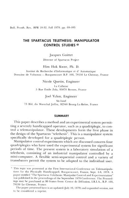
Bull . Prosth . Res., BPR 10-32, Fall 1979, pp . 69—105<br />
THE SPARTACUS TELETHESIS : MANIPULATOR<br />
CONTROL STUDIES a<br />
Jacques Guittet<br />
Director of <strong>Spartacus</strong> Project<br />
Him Hok Kwee, Ph . D.<br />
Institut de Recherche d'Informatique et d' Automatique<br />
Romaine de Voluceau — Rocquencourt B .P. 105, 78150 Le Chesnay, France<br />
Nicole Quetin, Engineer<br />
La Calhene<br />
5 Rue Emile Zola, 95870 Bezons, France<br />
Joel Yclon, Engineer<br />
Sit-Intel<br />
73 Bld . du Marechal joffre, 92340 Bourg-La-Reine, France<br />
SUMMARY<br />
This paper describes a method and an experimental system permitting<br />
a severely handicapped operator, such as a quadriplegic, to control<br />
a telenianipulator . <strong>The</strong>se developments form the first phase in<br />
the design of the <strong>Spartacus</strong> "telethesis" . This is a manipulator system<br />
specifically developed for a quadriplegic person.<br />
Manipulator control experiments which are discussed concern four<br />
quadriplegics who have used the experimental system for significant<br />
periods of time. <strong>The</strong> present system is a laboratory simulation of a<br />
telethesis, consisting of an industrial manipulator controlled by a<br />
mini-computer . A flexible semi-sequential control and a variety of<br />
transducers permit the system to be adapted to the individual user.<br />
" This topic was presented at the First International Conference on Telernanipulations<br />
for the Physically Handicapped, Rocquencourt, France, Sept . 4-6, 1978. A<br />
paper entitled "<strong>The</strong> <strong>Spartacus</strong> <strong>Telethesis</strong> : Manipular Control and Experimentation"<br />
was published in the proceedings of the September 1978 Conference . <strong>The</strong> Proceedings<br />
may be purchased at 90 francs from : Centre de Diffusion, I .R.I.A., B .P. 105,<br />
78150 Le Chesnay, France.<br />
<strong>The</strong> paper presented here is an updated (July 10, 1979) and expanded version, not<br />
to be considered a reprint .
ulletin of Prosthetics <strong>Research</strong> — Pall 1979<br />
Thus far, the experiments performed have shown the feasibility for<br />
the four quadriplegics to effectively control a telemanipulator, using<br />
head movements and some remaining arm movements in various<br />
modes of end-point control. In particular, a position control and a<br />
"piloting" type of velocity control, both with the addition of some<br />
force limitation, have given promising results.<br />
INTRODUCTION<br />
Within the framework of a nationwide robotics program, IRIA<br />
launched in 1975 the <strong>Spartacus</strong> Pilot Project, which aims at the development<br />
of a prototype telemanipulator controllable by quadriplegics<br />
due to spinalcord injury and other severe disabilities . <strong>The</strong><br />
duration of this project is limited to about 5 years . Some twenty research<br />
and development groups are or have been involved in various<br />
technical aspects of the project . Several clinical teams are participating,<br />
both in the definition of patient needs and in providing selected<br />
subjects for collaboration in our laboratory experiments.<br />
For the class of telemanipulator systems for the physically handicapped<br />
which neither replace a missing limb (like a prosthesis) nor<br />
assist a paralyzed limb (like an orthosis) but are instead tools not<br />
attached to the operator's body, we have adopted the name "telethesis".<br />
<strong>The</strong> design objectives have been established in close collaboration<br />
with the various teams involved, and have been further elaborated in<br />
discussions with potential users . <strong>The</strong> different compromises necessary<br />
between functional requirements, available technology, budgetary<br />
considerations, and the necessity to realize a prototype within 4<br />
years have resulted in the following specifications (Guittet, 1976):<br />
1. <strong>The</strong> telethesis should have an operating range covering a working<br />
table and shelves around it, and it should also be able to reach<br />
objects fallen on the floor . This corresponds with the operating range<br />
of the seated human operator, mainly using arm and trunk movements,<br />
but occasionally standing up to reach for objects just beyond<br />
his seated reach.<br />
2. <strong>The</strong> terminal device should be able to move at velocities of up to<br />
0.5 m/sec—but not much more, in order to assure operator safety.<br />
3. <strong>The</strong> telethesis should require as few adaptions of the environment<br />
as possible for its effective use and it should replace some of the<br />
special-purpose devices like page turners, feeders, environmental<br />
control systems, etc. <strong>The</strong> control of the telethesis should be adaptable<br />
to different physically handicapped operators, permitting them to<br />
utilize any remaining function either to operate a control or use it<br />
70
Guittet et al .: <strong>Spartacus</strong> <strong>Telethesis</strong><br />
independently . This should permit each user to have a control structure<br />
optimally adapted to his needs and his possibilities.<br />
4. <strong>The</strong> control of the movements of the manipulator should be<br />
effectuated in a way optimally adapted to the human operator, and<br />
end-point control of terminal device movements in an appropriate<br />
coordinate system seems indicated.<br />
5. Where necessary, the operator's task should be facilitated by<br />
automatic procedures ("reflexes") which in some way mimic similar<br />
semi-automatic mechanisms assisting the unimpaired person. Of<br />
course, the operator should at any time be able to override an automatic<br />
action and resume full command.<br />
<strong>The</strong> availability of and the fast developments in microcomputer<br />
techniques render these objectives realistic in terms of the price of an<br />
ultimate product, and industrial interest in more sophisticated automatic<br />
subsystems further justifies the efforts invested in these developments.<br />
It should be noted that the control structure for a telethesis must be<br />
more performant than the one required, for example, by an arm<br />
prosthesis that is mechanically attached to the operator's body . Those<br />
who have watched an amputee use a harness-mounted arm prosthesis<br />
will have noted that fine movements of the terminal device are controlled<br />
by trunk movements rather than by controlling the articulations<br />
of the prosthesis . This mode of operation is not available to the<br />
telethesis operator, who must control all movements of the terminal<br />
device exclusively by remotely controlling the movements of the powered<br />
articulations of the telemanipulator . Furthermore, high-level<br />
bilateral amputees using arm prostheses with several powered articulations<br />
usually have to invest a considerable amount of effort in coordinating<br />
the movements of the various articulations. Several laboratories<br />
are presently developing microcomputer-based systems to<br />
facilitate the control of these prostheses, and such an approach is even<br />
more important for the control of a telethesis.<br />
<strong>The</strong> present paper reports our studies to define a control procedure<br />
adapted to quadriplegic subjects, using a laboratory simulation<br />
of a telethesis. For this simulation we have used a commercial telemanipulator<br />
employed in nuclear research, controlled by a minicomputer<br />
and various prototypes of control transducers.<br />
<strong>The</strong> choice for a fixed workstation, rather than a manipulator carried<br />
on an electric wheelchair, has been made because the latter<br />
would impose severe restrictions on manipulator geometry, weight,<br />
and volume, thereby limiting the performance that could be obtained.<br />
A prototype telemanipulator, using the same technology as the nu-
Bulletin of Prosthetics <strong>Research</strong>—Fall 1979<br />
clear research model presently used but satisfying the design objectives<br />
as stated above, is presently in the final stage of construction<br />
(Vertut, 1978) . In several respects the system has become similar to<br />
the one developed in Heidelberg (Paeslack and Roesler, 1975;<br />
Roesler et al ., 1978) with which it has in common that it consists of an<br />
autonomous articulated manipulator mounted on a support that includes<br />
all the electronics necessary for its control . It is different, however,<br />
in manipulator specifications and the control configurations<br />
implemented. Its mechanical configuration is illustrated in Figure 1.<br />
GENERAL ORGANIZATION OF THE TELEMANIPULATOR SYSTEM<br />
<strong>The</strong> overall organization of the man-machine system is schematically<br />
represented in Figure 2 . <strong>The</strong> purpose of the "machine" is to use<br />
the quadriplegic's remaining means of communication, of whatever<br />
nature, to restore some of his lost capability to intervene in his physical<br />
environment through the use of some kind of mechanical manipulator.<br />
In this case the mechanical system is an articulated arm with<br />
six degrees of freedom, plus one for opening and closing of the grippers.<br />
Various elements have been added between the operator and<br />
the mechanical system to facilitate man-machine communication.<br />
On the operator side, a number of control transducers (which may<br />
be selected specifically in order to adapt to a particular person) form<br />
the interface between him and the rest of the system . Some experimental<br />
transducers will be described later.<br />
Between the control transducers and the mechanical arm, the information<br />
processing system is interposed, represented by the "decoding"<br />
and "movement coordination" blocks (Fig . 2) . On the manipulator<br />
side, the movement coordination routine has, as one of its<br />
functions, to effectuate a coordinate transformation (Liegeois and<br />
Coiffet, 1975; Metayer and Yclon, 1977). <strong>The</strong> coordinate transformer<br />
has as its inputs "gripper position" in Cartesian coordinates<br />
and "gripper orientation" expressed in "yaw" (about a vertical axis),<br />
pitch (about a horizontal axis) and roll (about its own axis) (Fig . 3). Its<br />
outputs are calculated manipulator motor positions necessary to obtain<br />
the joint angles that place the grippers in the specified position<br />
and orientation. <strong>The</strong> coordinate transformer is specific for the<br />
mechanical system used, but since its input does not depend on manipulator<br />
configuration, the rest of the system may be used with any<br />
mechanical system with its corresponding coordinate transformer.<br />
<strong>The</strong> only condition is that the mechanical system must be able to<br />
position and to orient the gripper according to the six degrees of<br />
freedom which have been mentioned.<br />
72
Guittet et al . :<br />
<strong>Spartacus</strong> <strong>Telethesis</strong><br />
I(,URE 1 . — Prototype of the autonomous <strong>Spartacus</strong> telethesis.<br />
Terminal device movements may also be controlled in other coordinate<br />
systems than the one mentioned above . In that case another<br />
coordinate transformer, independent of the mechanical configuration,<br />
may be added to precede the first one : this allows one to select<br />
different coordinate systems, dependent only on functional criteria<br />
relating to subject and task characteristic (Kwee, 1976) . Thus, control
Bulletin of Prosthetics <strong>Research</strong> — Fall 1979<br />
VISUAL<br />
FEEDBACK<br />
HUMAN<br />
SENSORY<br />
1<br />
CONTROL<br />
TRANSDUCERS<br />
CONTROL<br />
DISPLAY<br />
DECODING<br />
MOVEMENT<br />
COORDINATION<br />
"REFLEXES"<br />
ARTICULATED<br />
MANIPULATOR<br />
ENVIRONMENTAL<br />
TRANSDUCERS<br />
ENVIRONMENT<br />
FIGURE 2 .-Diagram of the general organization of the<br />
<strong>Spartacus</strong> Manipulator System.<br />
in polar, cylindrical, various terminal-device-related coordinates (or a<br />
mixture of them) may be implemented.<br />
<strong>The</strong> "decoding" section of Figure 2 has as its task the treatment,<br />
routing, and interpretation of the biological control signals in order to<br />
provide the proper command signals for the movement coordination<br />
section . Signal treatment includes the possibility of using a signal (i)<br />
proportionally (either as a position command or, after integration, as<br />
a velocity command) ; the possibility of using it (ii) in a discrete way<br />
with selectable timing and level-crossing characteristics ; or of using it<br />
(iii) in both ways in a mixed mode . It is this decoding section that<br />
74
Guittet et al . : <strong>Spartacus</strong> <strong>Telethesis</strong><br />
FIGURE 3. — Definition of control coordinates used as referenced to the gripper<br />
"wrist" joint. .„<br />
provides much of the flexibility of the system, giving it the modularity<br />
to accept a variety of transducers in different numbers, and to adapt<br />
control language and system parameters to individual users . <strong>The</strong> definition<br />
of a specific configuration of the system is accomplished by<br />
preprogramming, using a high-level interactive procedure on a<br />
minicomputer to specify the sequence of modes, transducers used,<br />
gain factors, thresholds, etc . This configuration may then be stored<br />
for later use. In the microprocessor version, each user may have his<br />
own plug-in preprogrammed memory element, specifying his particular<br />
configuration. This allows the system to be shared by different<br />
users, or to adapt to changes in user needs due to his changing physical<br />
condition, or to improved dexterity following training, or to new<br />
activities. <strong>The</strong> actual procedure of man-machine communication is<br />
described in the next section.<br />
Reflexes<br />
As mentioned in the introduction, various "reflexes" may be added<br />
in order to facilitate the manipulation task . Essentially, these reflexes
Bulletin of Prosthetics <strong>Research</strong> — Fall 1979<br />
are automatic procedures that modify or control manipulator movements<br />
in response to its interaction with its physical environment. In<br />
Figure 2, this interaction is measured by various environmental<br />
transducers, and in some way fed back to the movement coordination<br />
procedure.<br />
Soft Touch Reflex<br />
A first reflex that has been incorporated is the "soft touch", which<br />
automatically limits downward pressures exerted by the terminal device<br />
in a controllable way. Functionally, its effect is that the position of<br />
the terminal device is controlled by the operator until it meets a resistance<br />
in its downward movement . <strong>The</strong>n the downward action behaves<br />
in a spring-like manner, permitting the operator to control force<br />
rather than position. This soft touch limits forces exerted on objects<br />
or the working surface, but it allows tracking of surfaces while continually<br />
maintaining contact with them. This latter feature is necessary<br />
in such tasks as drawing, writing, or dialing a number on a<br />
standard dial telephone, and it generally aids in reducing the consequences<br />
of control errors.<br />
If a manipulator driven by torque motors and reversible transmissions<br />
is used, as is the case in our application, such a soft touch can be<br />
easily implemented by simple analog circuitry without requiring additional<br />
force transducers, by using the motor currents as a measure of<br />
the torques exerted (Kwee, 1978).<br />
Holding Reflex<br />
A second reflex being studied for implementation is a form of<br />
"holding reflex" that automatically adjusts the gripping force of the<br />
terminal device in order to avoid slippage of an object held (Clot et al .,<br />
1975). Its difference from similar systems reported before is the use<br />
of a specially developed semiconductive rubber "artificial skin" type<br />
of sensor to detect both slippage and gripping force . <strong>The</strong> measure of<br />
gripping force is necessary to compensate for the tendency to an<br />
unlimited augmentation of that force due to small perturbations, as<br />
studied by Clot et al.<br />
Grasping Reflex<br />
A third reflex under development is that of automatic grasping of<br />
an object once the gripper has been roughly positioned in the object's<br />
neighborhood . One system studied, which uses reflected infrared<br />
beam detectors on the gripper, then guides the gripper to grasp the<br />
object toward which it is aimed (Catros et al ., 1978 a,b) . Another<br />
76
Guittet et al . : <strong>Spartacus</strong> <strong>Telethesis</strong><br />
system makes use of ultrasound emitters and receivers on the gripper<br />
to detect the location of the object and guide the gripper (Clot et<br />
al ., 1977).<br />
Thus far, only the soft touch has been used as a reflex in medical<br />
applications ; the ultimate usefulness of the two others remains to be<br />
studied in medical applications. Reliability and cost considerations<br />
will further influence the decision about this implementation in the<br />
final system.<br />
Finally, feedback to the operator may be added, both to inform him<br />
about the state of the decoder that defines the interpretation of his<br />
analog signals, and to supplement his visual perception of terminaldevice<br />
movement with some information about forces exerted. In<br />
particular, information about gripping force and vertical forces may<br />
be helpful to the operator and a study on this subject is under way.<br />
MAN-MACHINE COMMUNICATION<br />
In order to realize manipulator end-point control, the operator<br />
must control the value of seven variables corresponding to seven<br />
degrees of freedom : six to define terminal-device position and orientation,<br />
and one to control opening and closing of the grippers.<br />
However, few quadriplegics can generate seven independently controllable<br />
signals to command these variables, and indeed, even if they<br />
were available, few operators would be able to control them simultaneously—or<br />
would even accept the burden of trying to do so for<br />
prolonged periods of time . <strong>The</strong>refore, a partially-sequential control<br />
strategy must be adopted (Kwee, 1976, Quetin, 1976) . In such a<br />
strategy, different groups of degrees-of-freedom are successively controlled<br />
by the same signals in successive "phases" of the composite<br />
movement . Thus, each phase is characterized by a specific routing of<br />
the control signals, allocating each of them to one of the degrees of<br />
freedom, while keeping the values for the non-allocated degrees of<br />
freedom constant in a buffer memory . From here on, the coordinate<br />
transformer takes care of controlling the joint motors in such a way as<br />
to make the terminal-device coordinates correspond with the<br />
operator-specified values.<br />
It should be noted that, if one defines gripper orientation with<br />
respect to absolute coordinates in space, this approach has as a consequence<br />
that gripper displacements are effectuated with the<br />
stabilized orientation in space if the operator does not modify it actively.<br />
This possibility to independently control gripper position and<br />
orientation greatly simplifies many manipulation tasks.<br />
Initial experiments, carried on before a computer was installed, for
Bulletin of Prosthetics <strong>Research</strong> ® Fall 1979<br />
technical reasons used a position control of the manipulator, using<br />
head and shoulder movements as inputs (Kwee and Guittet, 1977;<br />
Kwee, Parent and Guittet, 1977) . <strong>The</strong> relative ease of this form of<br />
control has led us to retain position control as one of the modes of<br />
operation of the system, thereby influencing the control procedure<br />
selected.<br />
A highly simplified diagram illustrating different aspects of the<br />
control procedure is shown as an example in Figure 4 . <strong>The</strong> human<br />
operator must be able to emit at least one continuous signal (i .e., a<br />
signal which he can voluntarily vary in a continuous manner between<br />
some minimum and maximum levels) in order to operate the manipulator.<br />
In addition, at least one discrete signal (i .e., an on/off twolevel<br />
signal) must be obtainable, if necessary coded within the continuous<br />
signal in the form of short pulses . Such a single-signal control<br />
would necessarily impose an entirely sequential control of the different<br />
variables. However, more signals can usually be found that are<br />
simultaneously controllable, allowing the control of several degrees of<br />
freedom in parallel. In Figure 4, it is assumed that three continuous<br />
signals are available in addition to two discrete signals.<br />
<strong>The</strong> discrete signals are used to select the way in which the continuous<br />
signals are used, to specify certain system parameters (e.g . gain),<br />
or to call for and interact with some automatic procedure . Only the<br />
first function is illustrated in Figure 4 by the clutch control and phaseselection<br />
signals. <strong>The</strong> clutch function permits the operator to couple or<br />
uncouple his continuous signals to or from the manipulator control.<br />
A zero-reset function associated with the coupling routine assures that<br />
upon coupling in the position-control mode, control is resumed at the<br />
current terminal-device position without a transient jump—or when<br />
coupling in the velocity control mode, assures that the current values<br />
of the control signals are taken as zero velocity. In all cases, uncoupling<br />
causes all movements to stop. In the position-control mode, the<br />
clutch function is used to reposition the control signals with respect to<br />
the movements controlled in order to shift the operating range in<br />
the coupled state. Thus successive displacements, each followed by<br />
repositioning of the control in the uncoupled state, permit the<br />
operator to cover large displacements by a "pumping" or "ratchet"<br />
type of action.<br />
<strong>The</strong> phase-selection signal (Fig. 4) permits the operator to use his<br />
continuous signals in three different ways: (i) position control of the<br />
grippers in Cartesian coordinates, (ii) position control of gripper yaw,<br />
pitch and roll (Fig. 3) and (iii) position control of yaw and pitch with<br />
velocity control of the displacement of the gripper in the direction of<br />
its own axis. <strong>The</strong> first two phases control terminal-device movements<br />
in the coordinate system, as earlier defined, for the basic coordinate<br />
78
Guittet et al .: <strong>Spartacus</strong> <strong>Telethesis</strong><br />
CONTINUOUS<br />
SIGNALS<br />
"CLUTCH"<br />
CONTROL<br />
DISCRETE<br />
SIGNALS<br />
PHASE"<br />
SELECTION<br />
POSITION<br />
ORIENTATION<br />
MEMORY<br />
TERMINAL - DEVICE<br />
COORDINATES<br />
COORDINATE TRANSFORMER<br />
MANIPULATOR JO/NT MOTORS<br />
FIGURE 4 . — Functional diagram of a control strategy<br />
with selection of three phases .
®uu®rr,n or rrosrnet'cs Keseareh — Fall 1979<br />
transformer. At any time no more than three variables are controlled<br />
by the operator and the others are held constant at their last values.<br />
Thus, displacements in the first phase take place with a constant<br />
orientation of the terminal device.<br />
<strong>The</strong> third phase combines position control of gripper orientation<br />
about the "wrist" joint with the control of its velocity in the direction<br />
of the gripper axis, either in forward or backward direction . This<br />
piloting mode is somewhat similar to Whitney's "resolved motion<br />
rate control" (Whitney, 1969) but with the control of gripper orientation<br />
effectuated about a vertical axis and a horizontal axis at the wrist<br />
joint rather than axes referenced to the gripper . In this mode the<br />
operator "flies" the terminal device like an airplane with remote control:<br />
this mode is particularly useful to cover long distances and to<br />
grasp or release objects . In addition, small rotations may be used to<br />
effectuate fine displacements.<br />
<strong>The</strong>se three phases together form an example of a control configuration.<br />
Generally, we call a configuration any set of phases sequentially<br />
selectable by the operator either in a cyclic fashion with a single direct<br />
command, or with more complicated coded commands permitting<br />
more rapid selective transitions.<br />
In the above example, three continuous signals were available for<br />
control purposes. If fewer signals are available, a configuration has to<br />
be used with more phases, with each of them controlling only two, or<br />
even one, degree of freedom . Furthermore, in a practical configuration<br />
some redundancy is often useful, combining the various degrees<br />
of freedom in different ways, in different phases, to facilitate specific<br />
manipulation tasks . <strong>The</strong>se combinations, and eventually the automatic<br />
routines required, are not always the same for different tasks, and<br />
in order to limit the number of phases within a configuration, a<br />
number of different configurations may be made accessible to the<br />
operator.<br />
Control Phases<br />
Summarized in Table 1 is an example of a more complete configuration<br />
of five phases that has been used in some of our experiments<br />
with the first two quadriplegic operators C .M . and B .L., both of whom<br />
were able to use three continuous control signals (two from head<br />
movements and one from gross arm movement ; see the section on the<br />
experimental system) . Phase 1 is a position control of terminal-device<br />
position in Cartesian coordinates, using a relatively high gain to cover<br />
an area of about 45 x 35 cm on the working table without "pumping" .<br />
<strong>The</strong> second phase is the same, but at a low gain to perform fine movements.<br />
<strong>The</strong> third phase is the piloting mode, which may also be used to<br />
80
Guittet et al .: <strong>Spartacus</strong> Teletl<br />
TABftfl 1 . —Exampl of a more coop/i ;- o al by C .M.<br />
Head movements in the frontal plane<br />
Head movements in the sag a plane<br />
lei transducer controlled by gross arm movement<br />
High<br />
gain<br />
Low<br />
gain<br />
Left/right<br />
Forward/backward<br />
lip/down<br />
Left/right<br />
Forwardlback.ward<br />
li I.)/ down<br />
Yaw'<br />
Gripper<br />
Roll<br />
Velocity<br />
net_<br />
open/close<br />
'Center of rotation at the wrist joint<br />
control terminal-device yaw and pitch without dispk the<br />
"wrist" joint (by maintaining a velocity zero) . <strong>The</strong> fourth p1 ase gives<br />
control of terminal-device roll and low-gain displacements in a hori<br />
zontal plane, which is particularly useful when pouring a drink t in<br />
fine assembly. Gripper opening and closing are controlled in its th<br />
phase--here it has been combined with a velocity control in t'<br />
tion of the grippers (forward and backward) as in the piloting i to le,<br />
but without the possibility to change direction . This is especially useful<br />
in the most delicate phases of manipulation involving grasping<br />
and releasing objects without inadvertently knocking them over.<br />
In other configurations, the high-gain and low gain position corn<br />
trol phases have been combined in one single phase at intermediate<br />
gain in order to reduce the number of phases and speed up their
Bulletin of Prosthetics <strong>Research</strong>—Fall 1979<br />
selection. However, recently another phase has been added for experimentation,<br />
consisting of a velocity control of movements in a<br />
horizontal plane and position control of vertical displacement. This<br />
phase is intended for long-distance displacements with stabilized<br />
gripper orientation without pumping, while maintaining fine position<br />
control of gripper height above the working surface.<br />
<strong>The</strong> selection of the configuration used, of the phase within a configuration,<br />
and of coupling or uncoupling of the clutch, can be effectuated<br />
in many ways and the experimental program allows us to test<br />
many of them. However, in view of the limited number of control<br />
signals available from the quadriplegic, a particularly interesting approach<br />
seems to be one in which a single discrete signal is used both to<br />
control the clutch and to change phases, and is very similar to the one<br />
used in many environmental control systems . <strong>The</strong> clutch function is<br />
operated by a short pulse, of a duration not exceeding a programmable<br />
time T, which switches from coupling to uncoupling or the<br />
other way around. In any case, the clutch is always uncoupled while<br />
the signal is "high". If the signal is maintained for more than the<br />
period T, then the next phase is entered, and another transition of<br />
phase is made after each consecutive period T . Typically, T is assigned<br />
a value of 400 to 600 milliseconds, depending on the subject<br />
and on the transducer used.<br />
When the signal is arrested, the system remains in the last phase<br />
and may be preprogramed to remain uncoupled, to be coupled, or to<br />
return the clutch to the state in which it was before the transition of<br />
phase. <strong>The</strong> first possibility is somewhat slower since it requires the<br />
emission of a pulse to couple after the selection of a phase, but avoids<br />
inadvertent gripper movements if the signal is arrested at a wrong<br />
phase . It also encourages the operator to assume a relaxed posture<br />
before resuming control, and at present we use this option with our<br />
quadri plegic operators. Finally, we propose to change configuration<br />
by entering a special phase within each configuration where the<br />
clutch-control pulse causes a transfer to the corresponding phase in<br />
the next configuration . This latter feature has yet to be the subject of<br />
an experiment.<br />
It should be noted that, in this section, a general outline has been<br />
presented of the approach in man-machine communication . Only<br />
those features used in the present stage of experimentation with<br />
quadriplegics have been discussed in some detail.<br />
82
Guittet et al .: <strong>Spartacus</strong> <strong>Telethesis</strong><br />
<strong>The</strong> Manipulator<br />
THE EXPERIMENTAL SYSTEM<br />
As mentioned in the introduction, the objective of the experiments<br />
reported here is to evaluate the feasibility of obtaining effective control<br />
of a telemanipulator by quadriplegics, allowing us to establish the<br />
design criteria for the telethesis.<br />
<strong>The</strong> experimental system uses a commercial CEA-La Calhene MA<br />
23 articulated manipulator (Vertut et al ., 1976), with six degrees of<br />
freedom and equipped with a two-fingered gripper (Fig . 5). <strong>The</strong> system<br />
is driven by d .c. torque motors with steel ribbon or cable reversible<br />
transmissions, controlled by analog position servo systems, giving<br />
it a low inertia, a relatively high natural compliance, and a limited<br />
reversible force output. Additional compliance has been incorporated,<br />
by analog circuitry, to provide both the "soft touch" feature<br />
and the control of gripper force once an object limits further closing<br />
of the grippers . <strong>The</strong> information-processing system has been implemented<br />
on a SOLAR 16/65 minicomputer with 48-k memory and<br />
its appropriate interface with the analog system (Metayer and Yclon,<br />
1977). Interconnections are made through a patch panel, preserving<br />
a maximum of modularity and experimental flexibility.<br />
Control Transducers<br />
<strong>The</strong> man-machine interface has been realized by a number of experimental<br />
control transducers, briefly described as follows:<br />
Head Movements<br />
Many quadriplegics still have good control of head movements if<br />
the trunk is properly stabilized . Two experimental transducers have<br />
been constructed, measuring head movements in the sagittal and<br />
frontal planes (Fig. 6 a, b, and c) (Kwee, 1977).<br />
For both transducers , the link with the head is realized by means of<br />
a V-shaped element, either variable in the form of crossed bars, or<br />
with a fixed 90 deg entrance for the parallelogram type transducer.<br />
In both cases they are spring-loaded to maintain contact with the<br />
head . This provides for easy installation on the subject and preserves<br />
the cosmesis of the subject's frontal appearance . Redesigning of these<br />
laboratory prototypes will, of course, be necessary before their eventual<br />
practical use.<br />
<strong>The</strong> same experimental structures include two transducers that<br />
may be used to measure vertical shoulder movement, each of them<br />
consisting of a simple bar clipped to the clothing at the shoulder and<br />
moving a potentiometer at the other end .
Bulletin of Prosthetics <strong>Research</strong>-- Fall 1979<br />
FIGLJ iiE 5 . --- Overall Me laboratory sy,din iota ,ubjcc~ B .L . mouuUng a<br />
tower<br />
Roller Transducer<br />
A transducer capable of detecting certain remaining arm movements<br />
of the subject (Fig. 7) consists of a padded roller attached to a<br />
84
Guittet et al .: <strong>Spartacus</strong> Teiethesis<br />
v .<br />
FORE WARD<br />
BACKWARD<br />
LEFT<br />
RIGHT<br />
FIGURE 6 (a). — Experimental head-movement transducer,<br />
crossed-bar type.<br />
10-turn potentiometer . For position control, this transducer has the<br />
advantage of remaining in place when it is not in use, which allows<br />
one to move progressively in repeated movements without uncoupling.<br />
It should be noted that the operator can assume control or<br />
release the roller with a minimal risk of inadvertently changing its<br />
position, which is particularly important for the quadriplegic using<br />
his paralyzed and insensitive hand . However, the lack of a spring<br />
return to a zero positon makes it more difficult to use for velocity<br />
control, and a joystick may be preferable for this purpose.<br />
Joystick<br />
A joystick, equipped with an elongated control bar, has actually<br />
been used with two subjects who do not have any functional displacements<br />
of the hand to operate a roller but who still are able to move an
Bulletin of Prosthetics <strong>Research</strong> — Fall 1979<br />
FIGURE 6 . (b and c)—Experimental haul-moy iienttransducer, parallelogram type:<br />
drawing (b) above, and photograph (c) on an experimental prototype.<br />
elbow in an active abduction movement (Fig . 8) . Only one of the two<br />
movements of the joystick has actually been used to capture the elbow<br />
movements.<br />
EMC, Signals<br />
86<br />
On several occasions myoelectric signals have been used, with elec-
Guittet et al . : <strong>Spartacus</strong> <strong>Telethesis</strong><br />
FIGURE 7 . — Roller-type transducer with pushbuttons behind it. <strong>The</strong> rear button<br />
(clutch) is equipped with a spring-loaded bar, making it controllable by gross arm<br />
movements, even during spasms. <strong>The</strong> separate "phase" button has been eliminated in<br />
later experiments.<br />
trodes located at various sites such as an inconspicuous place behind<br />
the ear, on the bridge of the nose (concealable by means of eyeglasses),<br />
and on the forehead (high enough to be hidden by overlying<br />
hair) . <strong>The</strong>se myoelectric signals have been used to provide both continuous<br />
signals in the classical way by rectifying and filtering, and
Bulletin of Prosthetics <strong>Research</strong> — Fall 1979<br />
FIGURE 8 . — Subject A .F. pouring a drink.<br />
discrete signals in the form of short pulses that could be recognized as<br />
such by the decoder (Yclon, 1976) . In particular, the pulses have been<br />
used to change the direction of the movement controlled, thereby<br />
making it possible to obtain a bidirectional proportional control from<br />
a single myoelectric signal.<br />
Switches<br />
We have also obtained discrete signals by means of large-size<br />
momentary-contact pushbuttons . <strong>The</strong>se buttons, controllable by gross<br />
motions, may be used either in their original commercially-available<br />
form, or modified by adding a spring-loaded bar to further facilitate<br />
control. Both forms are also shown in Figure 7 . Mercury switches and<br />
breath-operated pressure switches have also been used occasionally,<br />
but are more troublesome to use.<br />
88
Guittet et al . : <strong>Spartacus</strong> <strong>Telethesis</strong><br />
Laryngophone<br />
Instead of myoelectric or mechanical signals, we have recently used<br />
a laryngophone placed over the throat of the operator (Fig . 9) and<br />
connected to the inputs of the myoefactric amplifiers. A soft humming<br />
noise is sufficient to obtain relLN.e discrete control signals . :In<br />
addition, it is also possible to obtain p aional signals this way, but<br />
we have not yet tested this possibiliat in a control oak.<br />
<strong>The</strong> advantage of a laryngophone over EMG electrodes is its ea - of<br />
application and its reliability in use . A awback is that speech<br />
signal output. A special uncoupled se switching from tilt<br />
gophone signal to, e .g ., head moveni - ay be necessary tr , pa 1, it<br />
the subject to speak without having ontrol problems.<br />
9.—. Contrail transducta used wilt J .V. '`'ate the bit) agopatone attached<br />
around the neck and the joystick at the elbow .
Bulletin of Prosthetics <strong>Research</strong> — Fall 1979<br />
Glottomat<br />
Finally, another system using vocal signals but using an impedance<br />
measurement over the larynx to obtain the signal and a microprocessor<br />
system for signal analysis is the "glottomat", developed by Andre<br />
and Lhote (1978). This system uses a "melodic language", decoding<br />
successive pitch variations to obtain discrete output signals . <strong>The</strong> present<br />
system permits decoding of 16 signals, allowing it to be used for a<br />
random selection of phases, which we have scheduled for future experimentation.<br />
Display<br />
In order to facilitate the operator's task in using the clutch function<br />
and the system of sequentially-selectable phases, a simple display informs<br />
him about the state of coupling or uncoupling of the clutch and<br />
of the phase selected. In addition, each transition is accompanied by a<br />
short acoustic signal, liberating the operator from the necessity to<br />
observe the display at every transition . <strong>The</strong> only other form of sensory<br />
feedback added thus far is another light display, lighting up<br />
when the soft touch function limits downward motion. Without such a<br />
display, the gripper has a tendency to drop when an object is released<br />
while the soft touch is active.<br />
Safety Aspects<br />
As shown in Figure 5, manipulations are carried out on a working<br />
table of 130 x 75 cm with the operator seated in his wheelchair within<br />
the operating range of the gripper . Angular velocities and maximum<br />
torques have been limited by electronic circuits that cut the power on<br />
the three movements controlling displacement if a preset value is<br />
exceeded. In addition, the operator is protected by a window (best<br />
seen in Figure 10), equipped with microswitches that cut the motor<br />
power when the window is displaced. In the final system, reliability<br />
and hierarchy of electronic and programed safety features will be<br />
such that no window will be required, at least for the trained operator.<br />
Another aspect of operator safety is found in the programed link<br />
between head movements (if used) and corresponding gripper<br />
movements in forward/backward direction with respect to the<br />
operator. Ergonomically, the simplest link is the one in which the<br />
gripper moves in the same direction as the head . However, if contact<br />
is established between the gripper (or a tool held in it) and the head,<br />
an unstable system could result: the head being pushed backwards by<br />
the gripper, thereby making the latter move further towards the<br />
head, etc. Furthermore, a startle reflex, withdrawing the head (or an<br />
90
Guittet et al .: <strong>Spartacus</strong> <strong>Telethesis</strong><br />
extensor spasm) would make the gripper move towards the head.<br />
<strong>The</strong>se problems can be solved by inversing at least forward/backward<br />
motion of the gripper with respect to the corresponding movements<br />
of the subject — at the cost, of course, of more extensive training.<br />
EXPERIMENTAL SUBJECTS<br />
Numerous non-handicapped subjects and a number of physically<br />
handicapped subjects have volunteered to participate in our control<br />
experiments. Four handicapped subjects have participated for prolonged<br />
periods of time:<br />
Subject C. M.<br />
C.M . is a 49-year-old female with an asymmetric C-5 quadriplegia.<br />
<strong>The</strong> right deltoid and biceps are normal, and the wrist extensors are<br />
partially useable . However, right triceps, wrist flexors, and the muscles<br />
of the left arm are not functional. Head movements are normal,<br />
but occasional spasms force the head backwards. Virtually no sensibility<br />
remains in the upper limbs . She uses an electric wheelchair with<br />
joystick control.<br />
C . M. has been the first quadriplegic to cooperate in our control<br />
experiments, starting at a very early stage of the project, and has<br />
participated in 30 experimental sessions . She has used a large variety<br />
of transducers and control configurations . In later experiments she<br />
has used the parallelogram type head movement transducer (initially<br />
she used the crossed-bar type), a roller transducer, and a single<br />
spring-bar type switch for discrete signals, operated with the right<br />
hand using gross arm movements (Fig . 10).<br />
Subject B . L.<br />
B . L . is a 36-year-old male with a C-6 hyperspastic quadriplegia.<br />
Deltoids, biceps, and wrist extensors are functional, but not triceps or<br />
wrist flexors. However, the left arm is more functional than the right.<br />
<strong>The</strong> range of head movements is normal to the right but limited on<br />
the left. <strong>The</strong>re is a marked scoliosis causing the right shoulder to be at<br />
a lower level than the left, which tends to be worsened during spasms.<br />
He is seated in a specially-molded seat for added support in his electric<br />
wheelchair with joystick control.<br />
B . L. has participated in 17 experimental sessions, and he, too, has<br />
used a variety of transducers and control configurations . In later<br />
sessions he also used the parallelogram type head-movement transducer,<br />
a roller type transducer and a spring-bar switch ; he operated<br />
the two latter types with the left hand (Fig. 5) .
Bulletin of Prosthetics <strong>Research</strong> --- Fall 1979<br />
.--C .<br />
M. pouring a drink. Note the protecti, window separ,~~ hag her mm<br />
Subject A . F.<br />
A . F. is a 34-year-old male with an asymmetric C-3/C-4 quadriplegia<br />
. Trapezius and right deltoid muscles are functional, pemitting<br />
abduction of the right arm: of the other arm muscles only the right<br />
biceps remains partially functional . Osteomas of the elbow joints limit<br />
their action to only slight supination . A. F. suffers from flexor spasticity,<br />
beginning in the lower limbs, which may spread to the trunk and<br />
the arms.<br />
Control transducers used by A .F. are (Fig. 8) the parallelogram<br />
typt b ad-movement transducer, a joystick, to capture abduction at<br />
the °elbow, mounted with horizontal control bar, and a breathope~~<br />
d pressure transducer for discrete signals (later replaced by<br />
the lat yngophone) . A .F . has participated in 7 experimental sessions.<br />
92
Guittet et al .: <strong>Spartacus</strong> <strong>Telethesis</strong><br />
Subject J.V.<br />
J.V. is a 27-year-old male with a partial C-3 and complete C-4 quadriplegia.<br />
Right trapezius and both deltoids are functional, with better<br />
control of the left than the right . Other arm muscles are not functional<br />
but do not suffer from spasticity . Some extensor spasms occur<br />
occasionally after long periods of immobility . J.V. uses an electric<br />
wheelchair with joystick chin-control . For other functions he uses a<br />
mouthstick.<br />
J.V. has participated in a concentrated series of experiments over a<br />
period of 2 weeks, with 14 morning and/or afternoon sessions totalling<br />
26 hours behind the telemanipulator, of which 17 were actual<br />
experimentation. Final transducer used was the parallelogram<br />
head-movement transducer, joystick with horizontal control bar operated<br />
by the left elbow, and laryngophone for discrete signals<br />
(Fig. 9) .<br />
EXPERIMENTAL RESULTS<br />
For the first three subjects, the experimental sessions have been<br />
held at 2 to 4 week intervals and have combined the search for<br />
adapted transducers and control configurations with subject training.<br />
<strong>The</strong> continual evolution of the system sometimes interfered with the<br />
latter aspect.<br />
Control configurations have gradually evolved, from displacements<br />
in x, y, and z plus grippers to the ones mentioned in the section on<br />
man-machine communication . <strong>The</strong> experience gained with the first<br />
three subjects has permitted us to conduct an intensive 2-week learning<br />
experiment with the fourth subject, J .V.<br />
<strong>The</strong> first two subjects, C .M . and B .L., have two things in common:<br />
they both have been able to control a roller transducer with gross arm<br />
movements and they participated relatively early in the experimentation,<br />
With them, the most representative tasks, to serve as a reference,<br />
have been construction of a tower out of three building blocks (elements)<br />
and the tracing of a printed pathway on a sheet of paper.<br />
Other tasks that have been used include drawing and writing, painting,<br />
typewriting, dialing a number on a standard dial-type telephone,<br />
pouring a drink from a bottle into a glass, and inserting various<br />
shaped objects in the corresponding holes of a hollow box.<br />
<strong>The</strong> reference tasks, and the first four of the others, stress the<br />
ability of moving the terminal device in space with various degrees of<br />
precision. In addition, they require controlled contact between objects<br />
with a limited force, such as maintaining a pen on the paper in drawing.<br />
<strong>The</strong> "soft touch" feature has largely facilitated this interaction .
Bulletin at Prosthetics <strong>Research</strong> —Fall 1979<br />
<strong>The</strong> other tasks require control not only of the displacement of the<br />
terminal device, but also of its orientation.<br />
Initially, both subjects used head movements (as described earlier),<br />
a shoulder movement for vertical. displacements, and a myoelectric<br />
signal to actively open the grippers, which closed passively nA'hen no<br />
signal was emitted . Although both subjects succeeded in executing the<br />
displacement tasks, two problems were encountered : (i) it proved to<br />
be difficult to control shoulder movement independent of head<br />
movements, and maintenance of a fixed shoulder positich . was very<br />
tiring and interfered with breathing ; (ii) the simultaneous ontrol of<br />
both the myoelectric signal and other control motions di (iieult<br />
and tiring.<br />
<strong>The</strong>se problems have been solved with the introducHnn the<br />
roller-type transducer, to replace both the shoulder try<br />
the myoelectric control signal in two separate control I<br />
then, the performance of both subjects has improved s aific<br />
<strong>The</strong> additional phase, required to :place two control signals by one,<br />
actually facilitated the control + + I . . .ig and ckisitr ,, .' tl grippers.<br />
<strong>The</strong> reason for this is that this actsnl olmen correspr the most<br />
delicate movements in manipula tinn, when no<br />
+-novemerits<br />
are permitted . <strong>The</strong> recent addition of the ~ 'backward<br />
movement in the direction of the grippers, in coml .nnation with opening<br />
and closing, has further facilitated grasping and releasing of objects.<br />
<strong>The</strong> reference task of tracing a predrawn figure really is a tracking<br />
task in two dimensions — and has the advantage of leaving a record<br />
on paper . By imposing a trajectory to be followed, it is easier to interpret<br />
the drawn trajectory than in the case of free drawing or writing.<br />
It can be noted that lines in vertical or horizontal directions are the<br />
simplest to draw, although some deviation may occur at the nines<br />
when the clutch button is actuated in the pumping action . <strong>The</strong> drawing<br />
of diagonal lines clearly is more demanding, and initially they<br />
tend to be built up in a staircase-manner of horizontal and vertical<br />
elements . After training, they gradually tend to assume a straighter<br />
diagonal form, indicating that control of "composite" movements is<br />
being mastered.<br />
<strong>The</strong> reference test of tower building has been executed by both<br />
subjects in three modes : (i) using only displacements in rectilinear<br />
coordinates at high and low gains, which has been the first mode<br />
available to them, and still is the easiest one for fine control, (ii) using<br />
only piloting, as an exercise only, resulting in a rather tedious procedure,<br />
and (iii) using a mixture of the two, which would seem to be<br />
the best adapted procedure.<br />
94
et et al„: <strong>Spartacus</strong> Telethesls<br />
Both subjects have succeeded in executing this task in all three<br />
ways. However, thus far, only G .M. appreciates the added possibilities<br />
offered by the piloting mode while B .L. prefers to use the pumping<br />
action, even to cover larger distances . He only appreciated piloting in<br />
the more limited form of its combination with gripper opening and<br />
closing. (It should be noted that initially the velocity had been controlled<br />
with the roller transducer, which, as mentioned, does not provide<br />
a spring-return to zero velocity. To stop the movement, either<br />
the roller has to be moved actively to the region of zero velocity --<br />
which is not very critical—or the uncoupling signal has to be used .) In<br />
more recent experiments the velocity is controlled by head movements<br />
: the subject's forward/backward movements control gripper<br />
forward/backward velocity in the direction toward which it is pointing<br />
. This convention corresponds also with the safety requirement<br />
that the gripper will retreat from the head when the head is moved<br />
backward, unless the gripper is directed away from the head, which is<br />
potentially less dangerous and is a rather exceptional orientation.<br />
Table 2 summarizes the actions in which the different phases listed<br />
in Table 1 are used by G .M . <strong>The</strong> first five actions are elementary<br />
movements, which are followed by some examples of more complicated<br />
tasks . As indicated, a fast approach for long distance displacements<br />
is best executed in high-gain positioning or piloting modes . For<br />
the fine approach, low-gain positioning or piloting may be used, in<br />
combination with phase 5 (gripper opening/closing and forward/<br />
backward movement .)<br />
To completely control gripper orientation, two phases have to be<br />
used in this configuration. Drawing and writing may best be executed<br />
ie low-gain positioning mode, but a high gain is sometimes useful<br />
in drawing. Typewriting is best executed in the high gain positioning<br />
mode, which permits one to cover the keyboard without reverting to<br />
the "pumping" action . Typewriting, using an electric typewriter and<br />
an eraser-tipped pencil as a finger, has been quite feasible for both<br />
quadriplegics, although we have not yet tried to obtain a high speed.<br />
To optimize typing speed a special phase would be helpful, with a<br />
range of displacement just covering the keyboard and a preprogramed<br />
key-striking movement, but this has not yet been tried out.<br />
<strong>The</strong> tower contruction task, discussed before, and the "insertion<br />
box" task, requiring the subject to insert objects in corresponding<br />
holes at various orientations, are exercises corresponding to simple<br />
assembly tasks. <strong>The</strong> latter one is clearly much more difficult to execute<br />
and longer to learn, but G .M . has mastered this task which we are<br />
now beginning to use as a third reference task for the more experienced<br />
subjects .
Bulletin of Prosthetics <strong>Research</strong> — Fall 1979<br />
TABLE 2.-Example of the use of the phases ofTable 1 in different tasks ; open circles indicate<br />
phases of less importance.<br />
Phase<br />
N<br />
aC<br />
1<br />
2<br />
an<br />
>C ®<br />
3 4<br />
c a<br />
a ®<br />
~C +<br />
5<br />
v O<br />
cl,<br />
+<br />
Fast approach<br />
long distance<br />
Fine approach<br />
Gripper orientation<br />
Grasping/releasing<br />
Level transfer<br />
Drawing/writing<br />
o<br />
Typewriting<br />
Tower construction<br />
Insertion box<br />
o<br />
o<br />
Pouring o ® ® ® o<br />
<strong>The</strong> ability to pour the contents of one container into another is of<br />
importance both as an activity of daily living and in some professional<br />
activities. Its feasibility has been demonstrated by C .M., who is now<br />
capable of pouring a drink in a glass without spilling (Fig . 10) . <strong>The</strong><br />
movements of phase 4 of horizontal displacements and gripper roll<br />
have been combined specifically to facilitate this task . This is an<br />
example of the way in which the programing facility may be used to<br />
adjust the control configuration to suit the needs of an individual user<br />
in his activities. A more complete account of the experiments with<br />
C .M. and B .L. has been reported by Quetin (1978).<br />
96
Guittet et aL : <strong>Spartacus</strong> <strong>Telethesis</strong><br />
Subjects A.F . and J.V. have in common the inability to control the<br />
roller transducer since no sufficient voluntary movement of the hand<br />
remains for trouble-free operation . However, both have been able to<br />
use elbow abduction to control one degree of freedom with a joystick.<br />
In addition, other sources had to be found for the discrete signal.<br />
<strong>The</strong>ir severe functional impairment makes them even more typical<br />
candidates for use of a telethesis.<br />
Subject A .F. (Fig. 8) was the first subject at the C-3/C-4 level to<br />
operate the laboratory system, and several sessions with successive<br />
modifications of transducers and control configuration parameters<br />
have been necessary to arrive at an adapted system . In addition, a<br />
start has been made to invert the forward/backward control as mentioned<br />
under safety aspects.<br />
Initially, a configuration has been used with only two continuous<br />
control signals from head movements and a discrete signal from a<br />
pressure switch controlled by puffing through a small tube from the<br />
mouth . Although x, y, z type control was successfully effectuated at<br />
the first session, the lack of a third signal necessitated a larger number<br />
of phases, resulting in a more difficult and slower manipulation . At<br />
the third session, a shoulder transducer was added and a configuration<br />
similar to the one in Table 1 was used, but with the roller replaced<br />
by the shoulder up/down movement, and with only one positioning<br />
phase at intermediate gain with inverted, forward/backward<br />
movement. Shoulder movement proved to be tiring and relatively<br />
difficult to use, as had been the case with C .M . and R .L..<br />
At the fourth session, the shoulder transducer was replaced by the<br />
joystick at the elbow. Initially, some control problems arose because<br />
A.F . did not sense the degree of abduction of his elbow . For this<br />
reason the control bar has been elongated to enter into his visual field,<br />
thereby providing a visual feedback that facilitated its control . With<br />
this system good progress has been made during the following three<br />
sessions, although some problems have persisted with the inverted<br />
movement . In the final session reported here, the pressure switch has<br />
been replaced by the laryngophone to control the discrete signals,<br />
which has facilitated manipulation . A.F. has mastered the basic tasks,<br />
including pouring water from a bottle (Fig . 8) but further training will<br />
be necessary.<br />
<strong>The</strong> intensive 2-week experiment with J .V. required a more careful<br />
preparation and selection of control configuration, due to the severity<br />
of the disability. Initially, an experimental protocol had been established,<br />
designed to speed up learning while approaching a more clinical<br />
learning situation. <strong>The</strong> sequence of the exercises had been<br />
selected in such a way as to accentuate operator autonomy at each
Bulletin of Prosthetics <strong>Research</strong> -- Fall 1979<br />
stage of the learning procedure . Each task can be effectuated with the<br />
previously acquired skills without intervention of the teacher, and<br />
new elements are gradually introduced and reinforced.<br />
Initial trials were made with a spring-lever microswitch operated by<br />
shoulder elevation to operate the discrete signal, but again shoulder<br />
movement proved to be unreliable, due to the very critical adjustment<br />
required, and it has been replaced by the laryngophone, resulting in<br />
the transducer arrangement described in the section on experimental<br />
subjects . <strong>The</strong> configuration used is the same as the final one used by<br />
A.F.<br />
1 or the introduction of the foul phases we have used the following<br />
sequence: presentation of x, y, z positioning phase with the gripper<br />
half-open as a fork : free movements in the air, lifting and moving the<br />
elements of the tower (Fig . 5) suspended in the fork ; superimposing<br />
three elements to build the tower; disassembling the tower.<br />
Only a single phase is used, here, without control of gripper opening<br />
and closing. <strong>The</strong> clutch function and its use in the pumping<br />
movement are introduced during this time.<br />
This is followed by presentation of the changing of phase, and of<br />
the phase combining gripper opening and closing (with the joystick)<br />
and gripper velocity (with forward/backward head movements) . With<br />
the two phases now available, a variety of objects may be grasped,<br />
moved, superimposed, inserted in vertical holes, etc ., all with<br />
stabilized gripper. Some heavy objects are presented (steel cubes, a<br />
carafe filled with water) to demonstrate potential applications in daily<br />
living. In addition, the curve-tracing task is executed to start training<br />
of coordinated movements of x and y in the horizontal plane . <strong>The</strong><br />
tracing of diagonal lines proves to be particularly difficult in the beginning,<br />
due especially to the inverted forward/backward movement.<br />
<strong>The</strong> tracing task was maintained in every session as a reference task<br />
and to consolidate coordination training.<br />
Next came presentation of the phase combining rotation of the<br />
gripper about its axis (joystick control) with horizontal movements.<br />
After some introductory exercises, J .V. was soon capable of pouring<br />
water from the carafe into a glass without spilling (Fig . 11).<br />
Presentation of an intermediate phase, which features control of<br />
gripper yaw and pitch, but not of velocity, came as an introduction to<br />
piloting. As of now all degrees of freedom can be controlled, and a<br />
variety of tasks requiring orientation control are executed . Finally,<br />
the intermediate phase is replaced by the complete piloting phase and<br />
various exercises are executed with it, such as the insertion of elements<br />
in a hole (Fig . 12) . Once accustomed to this, J .V. appreciated<br />
98
Guittet et ale :<br />
<strong>Spartacus</strong> Tekkthesis<br />
FIGURE 11 . --TV . pouring a drink. In the background, the electric wife ; n> cut he<br />
cake is visible on the left.<br />
the possibilities offered by the piloting mode and learned to master its<br />
control completely.<br />
This part of the program occupied the first week of experimentation,<br />
covering 8 .5 hours of active exercises . During the second week,<br />
also covering 8.5 hours of manipulation, some exercises were repeated<br />
to consolidate operating skills, and a variety of more realistic<br />
applications have been executed : typewriting, writing, using a<br />
(slightly modified) electric knife to cut a cake (Fig. 11) and a steak,<br />
light a candle with a cigarette lighter, assemble constructions with<br />
large-size Lego elements (Fig . 13), turn pages of a telephone directory<br />
(Fig. 14), dial a telephone number and obtain the desired connection<br />
(Fig . 15), etc . With these results J .V . has been one of our best
Bulletin of Prosthetics <strong>Research</strong> -® Fall 1979<br />
FIGURE 12.—J .V. executing an insertion task, requiring both fine position and<br />
orientation control.<br />
operators (handicapped or not), discovering by himself many of the<br />
tricks necessary to perform the more complicated tasks . A more comprehensive<br />
account of this 2-week experiment has been presented by<br />
Gaillard et al. (1978) .<br />
CONCLUSION<br />
<strong>The</strong> experiments conducted thus far have shown that, with the<br />
system outlined here, the control of a telemanipulator by quadriplegics<br />
is indeed feasible. Furthermore, there do not appear to be<br />
large differences in quality and speed of control between the spinalcord-injured<br />
patient and non-handicapped — when given the same<br />
type of control. However, in general, large differences exist between<br />
100
Guittet et al . : Spertacus <strong>Telethesis</strong><br />
FIGL RE 13 . — Lego (large model) constructions made by J .V. follow Jug models indicated<br />
on the box.<br />
different subjects in their rate of learning to master the control and,<br />
independent of this, to conceptualize the movement to be made.<br />
Position control of terminal device movement, by head movements<br />
in two directions, has proved to be a rather convenient way of controlling<br />
a manipulator . <strong>The</strong> roller-type of transducer appears to be welladapted<br />
for position control to those subjects who still have some arm<br />
movements left, even without remaining sensation . In contrast,<br />
shoulder movements appear to be difficult to control independently<br />
of head movements . A joystick to capture elbow abduction may be<br />
used with good results to replace the roller transducer where necessary<br />
(and possible), but its use requires a more frequent pumping<br />
action.<br />
Associating forward/backward head movement to corresponding<br />
gripper movements (but inverted in direction to augment safety)
Bulletin of Prosthetics <strong>Research</strong> Fall 1979<br />
FIGURE 14. -- J .V. tui Ling pages of a telephone directory, using a guru-tipped pencil<br />
as a "finger ."<br />
seems to be acceptable but at the price of an increased learning time.<br />
<strong>The</strong> ability to perform manipulations without a protective window,<br />
thereby permitting the use of a mouthstick to operate on an object<br />
held by the gripper, would appear to justify such an investment.<br />
<strong>The</strong> use of a modular system has permitted us to experiment with<br />
different control strategies and different transducers without extensive<br />
reprograming . It seems to be desirable to maintain modularity<br />
in the final system, although a somewhat reduced number of possibilities<br />
will be adequate to select for each user an adapted control<br />
configuration . <strong>The</strong> semisequential control in different phases, in<br />
combination with clutch function, appears to be a reasonable procedure<br />
for controlling a telemanipulator with a limited number of control<br />
signals. Furthermore, it is feasible to implement this type of control<br />
on a microprocessor within the constraints of reasonable cost.<br />
102
Guittet et aL :<br />
<strong>Spartacus</strong> <strong>Telethesis</strong><br />
~tE 15. -- J .V. dialing a telephone numb( r an d<br />
connection .<br />
,ncceeding in obtainin the right<br />
ACKNOWLEDGMENTS<br />
<strong>The</strong> authors wish to thank their many colleagues affiliated with the<br />
<strong>Spartacus</strong> Project for their contributions to the work reported in this<br />
paper. In particular, they wish to acknowledge the help of Mrs . C.<br />
Moucheront and Messrs . L.S. Coles, G. Cristau, J .L. Ehrwein, A.<br />
Fercod, J .P. Gaillard, B . Franck, O . Goyeau, A.Leduc, B. Lesigne, Ph.<br />
Metayer, M . Parent, M . Petit, and J. Virazels . <strong>The</strong>y also acknowledge<br />
the contributions of Prof. A. Grossiord's group for their stimulatadvice<br />
and the presentation of selected experimental subjects.<br />
is work has been supported by the French Ministries of Industry,<br />
<strong>Research</strong>, and Health.
Bulletin of Prosthetics <strong>Research</strong> — Fall 1979<br />
REFERENCES<br />
Andre, P., and F . Lhote : Strategic et Langage Melodique de Commande d'un Robot<br />
d'Assistance Medicale . Proc . First Int . Conf. on Telemanipulators for the Physically<br />
Handicapped, Rocquencourt, France, pp . 185-491, 1978.<br />
Catros, J.Y ., A . Dore, B . Espiau, M. Parent, and J . Yclon: Automatic Grasping Using<br />
Infrared Sensors . Proc. of the `Industrie Roboter Symposium, Stuttgart, West Germany,<br />
1978 (version a).<br />
Catros, J .Y., A. Dore, B . Espiau, J. Guittet, M. Parent, and J . Yclon: La Telethese<br />
<strong>Spartacus</strong> ; Saisie Semi-Automatique . Proc. First Intern . Conf. on Telemanipulators<br />
for the Physically Handicapped, Rocquencourt, France, 301-314, Sept . 4-6, 1978<br />
(version b).<br />
Clot, J ., P . Rabischong, E . Peruchon, and j . Falipon : Principles and Applications of the<br />
Artificial Skin (ASS) . Proc. of the Fifth Symposium on External Control of Human<br />
Extremities, Dubrovnik, Yugoslavia, 1975.<br />
Clot, J ., P . Glieze, and C . Menissez : Etude et Realisation D'un Dispositif Permettant le<br />
Positionnement Automatique d'un Outil de Prehension Grace a des Capteurs de<br />
Proximite Ultra-Sonores . Rapport <strong>Spartacus</strong> EC-18 . IRIA, Rocquencourt, France,<br />
1977.<br />
Gaillard, J .P ., J. Guittet, H .H. Kwee, and N . Quetin: La Telethese <strong>Spartacus</strong>, Bilan de<br />
17 Heures d'Experimentation avec un Tetraplegique de Niveau C5 . Proc. Second<br />
Europ. Para-medical Symp . on Spinal Cord Injuries, Lyon, France, F 1-55, 1978.<br />
Goyau, O. and H.H . Kwee: <strong>The</strong> <strong>Spartacus</strong> <strong>Telethesis</strong> : "Assisted Holding" . Proc. First<br />
Intern. Conf. on Telemanipulators for the Physically Handicapped, Rocquencourt,<br />
France, Sept. 4-6, 1978.<br />
Guittet, J . : <strong>The</strong> <strong>Spartacus</strong> Project : Aids for the Physically Handicapped . Proc. of the<br />
Second International Congress on the Technology for Prosthetics and Functional<br />
<strong>Rehabilitation</strong>, Cannes, France, 1976.<br />
Kwee, H .H .: Quelques Reperes de Commande pour Tetraplegiques . I .R.I .A. Report,<br />
<strong>Spartacus</strong> Project, Le Chesnay, France, 1976.<br />
Kwee, I-I .H . : Capteurs Cephaliques Articules. Jeurnees Robotiques, I .R.I .A., Le Chesnay,<br />
France, 1977.<br />
Kwee, H .H . : <strong>The</strong> <strong>Spartacus</strong> <strong>Telethesis</strong> : Soft Touch . Proc. First Intern . Conf. on Telemanipulators<br />
for the Physically Handicapped, Rocquencourt, France, Sept . 4-6, 1978.<br />
Kwee, H .H . and J . Guittet : <strong>Spartacus</strong> : A Telemanipulator for the Physically Handicapped<br />
. Proc. I .S .P .O. World Congress, New York, USA, 1977.<br />
Kwee, H .H., M . Parent, and J . Guittet: Langage de Commande d'un Telemanipulateur<br />
: Experience sur le MA-23. I .R.I .A. Report HI-006, <strong>Spartacus</strong> Project.<br />
Le Chesnay, France, 1977.<br />
Kwee, H .H. and N. Quetin: Experiences de Telemanipulation par deux Tetraplegiques<br />
: Premiere Annee . <strong>Spartacus</strong> Report HL-021, La Calhene, Bezons, France.<br />
Liegeois, A . and P. Coiffet : Etude des Automatismes Intervenant dans la Commande<br />
d'un Manipulateur pour Handicapes . I .R.I .A. Report, SC-015 <strong>Spartacus</strong> Project, I .e<br />
Chesnay, France, 1975.<br />
Metayer, Ph . and J . Yclon : Description du Systeme Informatique d'Experimentation<br />
du Laboratoire <strong>Spartacus</strong> a 1'I .R.I .A . 1 .R.I .A. Report SC-016, <strong>Spartacus</strong> Project, Le<br />
Chesnay, France, 1977.<br />
Paeslack, V. and H. Roesler: Medical Manipulators for the Seriously Disabled . Annual<br />
Report, Stiftung <strong>Rehabilitation</strong>, Heidelberg, West Germany, 1975.<br />
Quetin, N . : Scenarios d'Organisation de la Commande II . <strong>Spartacus</strong> Report HL-002,<br />
La Calhene, Bezons, France, 1976.<br />
104
Guittet et al .: <strong>Spartacus</strong> <strong>Telethesis</strong><br />
Quetin, N .: Experiences de Telemanipulation par deux Tetraplegiques : Premiere annee.<br />
<strong>Spartacus</strong> Report HL-021, La Calhene, Bezons, France, 1978.<br />
Roesler, H ., H. J. Koppers, and E . Schmalenbach: <strong>The</strong> Medical Manipulator and Its<br />
Adapted Environment: A System for the <strong>Rehabilitation</strong> of the Severely Handicapped.<br />
Proc. First Int. Conf. on Telemanipulators for the Physically Handicapped,<br />
Rocquencourt, France, 1978.<br />
Vertut, J . : La Telethese <strong>Spartacus</strong> : Conception Mecanique du Manipulateur MAT 1.<br />
Proc. First Intern . Conf. on Telemanipulators for the Physically Handicapped, Rocquencourt,<br />
France, Sept . 4-6, 1978.<br />
Vertut, J., J. Charles, P . Coiffet, and P . Petit : Advance of the New MA-23 Force-<br />
Reflecting Systems . Proc . Second CISM-IFTOMM Symposium, Romansy, Warsaw,<br />
Poland, 1976.<br />
Whitney, D .E .: Resolved Motion Rate Control of Manipulators and Human Prostheses.<br />
IEEE Trans . on Man Machine Syst., MMS-10, 47-53, 1969.<br />
Yclon, J .: Etude de la Commande d'un Processus par les Signaux Biologiques . Report,<br />
SC-003, SIT-INTEIJ<strong>Spartacus</strong>, Bourg-la-Reine, France, 1976 .