69730 Parts List - Harbor Freight Tools
69730 Parts List - Harbor Freight Tools
69730 Parts List - Harbor Freight Tools

Create successful ePaper yourself
Turn your PDF publications into a flip-book with our unique Google optimized e-Paper software.
Table of Contents<br />
SAFETY SETUP<br />
OPERATION MAINTENANCE<br />
Specifications.............................................. 2<br />
Safety.......................................................... 3<br />
Setup........................................................... 6<br />
Operation..................................................... 8<br />
Specifications<br />
Displacement<br />
Engine Type<br />
Cooling System<br />
Fuel<br />
Type<br />
Capacity<br />
Maintenance............................................... 12<br />
Troubleshooting.......................................... 16<br />
Warranties.................................................. 18<br />
<strong>Parts</strong> <strong>List</strong>s and Diagrams........................... 20<br />
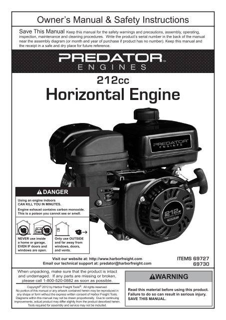
212cc<br />
Horizontal Single Cylinder<br />
4 stroke OHV<br />
69727: Meets EPA phase III and<br />
CARB emissions standards<br />
<strong>69730</strong>: Meets EPA phase III<br />
emissions standards<br />
Forced air cooled<br />
87+ octane unleaded gasoline<br />
0.9 Gallon (3.6 Liter)<br />
10W-30 above 32° F<br />
5W-30 at 32° F or below<br />
0.5 Quart<br />
Engine Oil<br />
Type SAE<br />
Capacity<br />
Run Time @ 50% Load<br />
with full tank<br />
3 hr.<br />
Sound Level at 22 feet<br />
104 dB<br />
Bore x Stroke<br />
70 mm x 55 mm<br />
Compression Ratio 8.5:1<br />
Rotation viewed from PTO<br />
(power takeoff - the output shaft)<br />
Shaft<br />
Spark Plug<br />
Counterclockwise<br />
Shaft 3/4″ x 2.43″<br />
Keyway<br />
End Tapped<br />
Type<br />
Gap<br />
3/16″ (4.76 mm)<br />
5/16″ - 24 UNF<br />
NGK ® BP-6ES<br />
NHSP ® / Torch ® F6TC<br />
0.7 - 0.8 mm<br />
Intake 0.10 - 0.15 mm<br />
Valve Clearance<br />
Exhaust 0.15 - 0.20 mm<br />
Speed Idle 1,800 ± 50 RPM<br />
Page 2 For technical questions, please call 1-800-520-0882. ITEM 69727<br />
<strong>69730</strong>
WARNING SYMBOLS AND DEFINITIONS<br />
This is the safety alert symbol. It is used to alert you to potential personal injury hazards.<br />
Obey all safety messages that follow this symbol to avoid possible injury or death.<br />
Indicates a hazardous situation which, if not avoided,<br />
will result in death or serious injury.<br />
Indicates a hazardous situation which, if not avoided,<br />
could result in death or serious injury.<br />
Indicates a hazardous situation which, if not avoided,<br />
could result in minor or moderate injury.<br />
SAFETY<br />
Addresses practices not related to personal injury.<br />
Symbol Definitions<br />
Symbol<br />
RPM<br />
HP<br />
Property or Statement<br />
Revolutions Per Minute<br />
Horsepower<br />
Safety Warnings<br />
WARNING marking concerning<br />
Risk of Eye Injury. Wear ANSI-approved<br />
safety goggles with side shields.<br />
Read the manual before set-up and/or use.<br />
WARNING marking concerning<br />
Risk of Hearing Loss.<br />
Wear hearing protection.<br />
Symbol<br />
Property or Statement<br />
WARNING marking concerning<br />
Risk of Respiratory Injury.<br />
Operate engine OUTSIDE and far away<br />
from windows, doors, and vents.<br />
WARNING marking concerning<br />
Risk of Fire while handling fuel.<br />
Do not smoke while handling fuel.<br />
WARNING marking concerning<br />
Risk of Fire.<br />
Do not refuel while operating.<br />
Keep flammable objects away from engine.<br />
WARNING! Read all instructions.<br />
Failure to follow all instructions listed below may result in fire, serious injury and/or DEATH.<br />
The warnings and precautions discussed in this manual cannot cover all possible conditions and<br />
situations that may occur. It must be understood by the operator that common sense and caution<br />
are factors which cannot be built into this product, but must be supplied by the operator.<br />
SAVE THESE INSTRUCTIONS<br />
MAINTENANCE OPERATION<br />
SETUP<br />
ITEM 69727<br />
<strong>69730</strong><br />
For technical questions, please call 1-800-520-0882.<br />
Page 3
SAFETY SETUP<br />
OPERATION MAINTENANCE<br />
Set up Precautions<br />
1. Gasoline fuel and fumes are flammable, and<br />
potentially explosive. Use proper fuel storage<br />
and handling procedures. Do not store fuel<br />
or other flammable materials nearby.<br />
2. Have multiple ABC class fire extinguishers nearby.<br />
3. Operation of this equipment may create sparks<br />
that can start fires around dry vegetation. A spark<br />
arrestor may be required. The operator should<br />
contact local fire agencies for laws or regulations<br />
relating to fire prevention requirements.<br />
Operating Precautions<br />
1. CARBON MONOXIDE HAZARD<br />
Using an engine indoors CAN KILL<br />
YOU IN MINUTES.<br />
Engine exhaust contains carbon<br />
monoxide. This is a poison you cannot<br />
see or smell.<br />
NEVER use inside a home or garage,<br />
EVEN IF doors and windows are open.<br />
Only use OUTSIDE and far away from windows,<br />
doors, and vents.<br />
2. Keep children away from the equipment,<br />
especially while it is operating.<br />
3. Keep all spectators at least six feet<br />
from the Engine during operation.<br />
4. Fire Hazard! Do not fill gas tank while engine is<br />
running. Do not operate if gasoline has been spilled.<br />
Clean spilled gasoline before starting engine.<br />
Do not operate near pilot light or open flame.<br />
5. Do not touch engine during use.<br />
Let engine cool down after use.<br />
6. Never store fuel or other flammable<br />
materials near the engine.<br />
7. Only use a suitable means of transport and<br />
lifting devices with sufficient weight bearing<br />
capacity when transporting the Engine.<br />
8. Secure the Engine on transport vehicles to<br />
prevent the tool from rolling, slipping, and tilting.<br />
9. Industrial applications must follow<br />
OSHA requirements.<br />
4. Set up and use only on a flat, level,<br />
well‐ventilated surface.<br />
5. Wear ANSI-approved safety goggles, heavy-duty<br />
work gloves, and dust mask/respirator during set up.<br />
6. Use only lubricants and fuel recommended<br />
in the Specifications chart of this manual.<br />
10. Do not leave the equipment unattended when it is<br />
running. Turn off the equipment (and remove safety<br />
keys, if available) before leaving the work area.<br />
11. Engine can produce high noise levels.<br />
Prolonged exposure to noise levels<br />
above 85 dBA is hazardous to hearing.<br />
Always wear ear protection when operating or<br />
working around the gas engine while it is operating.<br />
12. Wear ANSI-approved safety glasses, hearing<br />
protection, and NIOSH-approved dust mask/<br />
respirator under a full face shield along<br />
with steel-toed work boots during use.<br />
13. People with pacemakers should consult their<br />
physician(s) before use. Electromagnetic fields in<br />
close proximity to a heart pacemaker could cause<br />
pacemaker interference or pacemaker failure.<br />
Caution is necessary when near the<br />
engine’s magneto or recoil starter.<br />
14. Use only accessories that are recommended<br />
by <strong>Harbor</strong> <strong>Freight</strong> <strong>Tools</strong> for your model.<br />
Accessories that may be suitable for one<br />
piece of equipment may become hazardous<br />
when used on another piece of equipment.<br />
15. Do not operate in explosive atmospheres,<br />
such as in the presence of flammable<br />
liquids, gases, or dust. Gasoline-powered<br />
engines may ignite the dust or fumes.<br />
16. Stay alert, watch what you are doing and<br />
use common sense when operating this<br />
piece of equipment. Do not use this piece of<br />
equipment while tired or under the influence<br />
of drugs, alcohol or medication.<br />
17. Do not overreach. Keep proper footing and<br />
balance at all times. This enables better control<br />
of the equipment in unexpected situations.<br />
18. Use this equipment with both hands<br />
only. Using equipment with only one hand<br />
can easily result in loss of control.<br />
19. Dress properly. Do not wear loose clothing or<br />
jewelry. Keep hair, clothing and gloves away<br />
from moving parts. Loose clothes, jewelry or<br />
long hair can be caught in moving parts.<br />
Page 4 For technical questions, please call 1-800-520-0882. ITEM 69727<br />
<strong>69730</strong>
Operating Precautions (cont.)<br />
20. <strong>Parts</strong>, especially exhaust system components,<br />
get very hot during use. Stay clear of hot parts.<br />
21. Do not cover the engine or<br />
equipment during operation.<br />
22. Keep the equipment, engine, and<br />
surrounding area clean at all times.<br />
23. Use the equipment, accessories, etc., in accordance<br />
with these instructions and in the manner intended for<br />
the particular type of equipment, taking into account<br />
the working conditions and the work to be performed.<br />
Use of the equipment for operations different from<br />
those intended could result in a hazardous situation.<br />
24. Do not operate the equipment with known<br />
leaks in the engine’s fuel system.<br />
25. This product contains or, when used, produces a<br />
chemical known to the State of California to cause<br />
cancer and birth defects or other reproductive harm.<br />
(California Health & Safety Code § 25249.5, et seq.)<br />
Service Precautions<br />
1. Before service, maintenance, or cleaning:<br />
a. Turn the engine switch to its “OFF” position.<br />
b. Allow the engine to completely cool.<br />
c. Then, remove the spark plug<br />
cap from the spark plug.<br />
2. Keep all safety guards in place and in<br />
proper working order. Safety guards include<br />
muffler, air cleaner, mechanical guards,<br />
and heat shields, among other guards.<br />
3. Do not alter or adjust any part of the<br />
equipment or its engine that is sealed by the<br />
manufacturer or distributor. Only a qualified<br />
service technician may adjust parts that may<br />
increase or decrease governed engine speed.<br />
4. Wear ANSI-approved safety goggles, heavy-duty<br />
work gloves, and dust mask/respirator during service.<br />
5. Maintain labels and nameplates on the equipment.<br />
These carry important information.<br />
If unreadable or missing, contact<br />
<strong>Harbor</strong> <strong>Freight</strong> <strong>Tools</strong> for a replacement.<br />
6. Have the equipment serviced by a qualified repair<br />
person using only identical replacement parts.<br />
This will ensure that the safety of the equipment<br />
is maintained. Do not attempt any service or<br />
maintenance procedures not explained in this<br />
manual or any procedures that you are uncertain<br />
about your ability to perform safely or correctly.<br />
7. Store equipment out of the reach of children.<br />
26. When spills of fuel or oil occur, they must be<br />
cleaned up immediately. Dispose of fluids and<br />
cleaning materials as per any local, state, or<br />
federal codes and regulations. Store oil rags in<br />
a bottom-ventilated, covered, metal container.<br />
27. Keep hands and feet away from moving parts. Do<br />
not reach over or across equipment while operating.<br />
28. Before use, check for misalignment or binding of<br />
moving parts, breakage of parts, and any other<br />
condition that may affect the equipment’s operation.<br />
If damaged, have the equipment serviced<br />
before using. Many accidents are caused<br />
by poorly maintained equipment.<br />
29. Use the correct equipment for the application.<br />
Do not modify the equipment and do not use the<br />
equipment for a purpose for which it is not intended.<br />
8. Follow scheduled engine and<br />
equipment maintenance.<br />
Refueling:<br />
1. Do not smoke, or allow sparks, flames,<br />
or other sources of ignition around the<br />
equipment, especially when refuelling.<br />
2. Do not refill the fuel tank while the<br />
engine is running or hot.<br />
3. TO PREVENT FUEL LEAKAGE AND<br />
FIRE HAZARD, do not fill fuel above<br />
the bottom of fuel strainer.<br />
Max Fuel<br />
DO NOT OVERFILL!<br />
4. Do not fill fuel tank to the top. Leave a little<br />
room for the fuel to expand as needed.<br />
5. Refuel in a well-ventilated area only.<br />
6. Wipe up any spilled fuel and allow excess<br />
to evaporate before starting engine.<br />
To prevent FIRE, do not start the engine<br />
while the smell of fuel hangs in the air.<br />
SAVE THESE INSTRUCTIONS.<br />
SAFETY<br />
MAINTENANCE OPERATION<br />
SETUP<br />
ITEM 69727<br />
<strong>69730</strong><br />
For technical questions, please call 1-800-520-0882.<br />
Page 5
Set Up<br />
SAFETY SETUP<br />
OPERATION MAINTENANCE<br />
Read the ENTIRE IMPORTANT SAFETY INFORMATION section at the beginning of this manual<br />
including all text under subheadings therein before set up or use of this product.<br />
TO PREVENT SERIOUS INJURY:<br />
Operate only with proper spark arrestor installed.<br />
Operation of this equipment may create sparks that<br />
can start fires around dry vegetation.<br />
A spark arrestor may be required.<br />
The operator should contact local fire<br />
agencies for laws or regulations relating<br />
to fire prevention requirements.<br />
At high altitudes, the engine’s carburetor, governor<br />
(if so equipped), and any other parts that control<br />
the fuel-air ratio will need to be adjusted by a<br />
qualified mechanic to allow efficient high-altitude<br />
use and to prevent damage to the engine and<br />
any other devices used with this product.<br />
For item 69727: The emission control system for this<br />
Engine is warranted for standards set by the U.S.<br />
Environmental Protection Agency and by the California Air<br />
Resources Board (also known as CARB). For warranty<br />
information, refer to the last pages of this manual.<br />
For item <strong>69730</strong>: The emission control system for<br />
this Engine is warranted for standards set by the<br />
U.S. Environmental Protection Agency. For warranty<br />
information, refer to the last pages of this manual.<br />
WARNING! DO NOT INSTALL THIS<br />
ENGINE ON A VEHICLE.<br />
Page 6 For technical questions, please call 1-800-520-0882. ITEM 69727<br />
<strong>69730</strong>
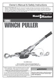
Engine Controls<br />
Air Filter<br />
Fuel Cap<br />
SAFETY<br />
Starter<br />
Handle<br />
Oil Drain Plug<br />
Throttle<br />
Choke<br />
Fuel Valve<br />
Engine<br />
Switch<br />
Muffler<br />
Dipstick<br />
MAINTENANCE OPERATION<br />
SETUP<br />
ITEM 69727<br />
<strong>69730</strong><br />
For technical questions, please call 1-800-520-0882.<br />
Page 7
Operation<br />
Read the ENTIRE IMPORTANT SAFETY INFORMATION section at the beginning of this manual<br />
including all text under subheadings therein before set up or use of this product.<br />
SAFETY SETUP<br />
OPERATION MAINTENANCE<br />
Pre-Start Checks<br />
Inspect engine and equipment looking for damaged, loose, and missing parts before set up<br />
and starting. If any problems are found, do not use equipment until fixed properly.<br />
Checking and Filling Engine Oil<br />
NOTICE: Your Warranty is VOID if the engine’s<br />
crankcase is not properly filled with oil before<br />
each use. Before each use, check the oil level.<br />
Do not run the engine with low or no engine oil.<br />
Running the engine with no or low engine oil<br />
WILL permanently damage the engine.<br />
1. Make sure the engine is stopped and is level.<br />
2. Close the Fuel Valve.<br />
3. Clean the top of the Dipstick and the area around it.<br />
Remove the Dipstick by threading it counterclockwise,<br />
and wipe it off with a clean lint free rag.<br />
4.<br />
Full level<br />
Reinsert the Dipstick without threading it in and<br />
remove it to check the oil level. The oil level<br />
should be up to the full level as shown above.<br />
Full level<br />
5. If the oil level is at or below the low mark add the<br />
appropriate type of oil until the oil level is at the<br />
proper level. SAE 10W‐30 oil is recommended<br />
for general use. (The SAE Viscosity Grade chart<br />
on page 13 in the Service section shows other<br />
viscosities to use in different average temperatures.)<br />
6. Thread the dipstick back in clockwise.<br />
NOTICE: Do not run the engine with too little oil.<br />
The engine will be permanently damaged.<br />
Page 8 For technical questions, please call 1-800-520-0882. ITEM 69727<br />
<strong>69730</strong>
Checking and Filling Fuel<br />
WARNING! TO PREVENT SERIOUS<br />
INJURY FROM FIRE:<br />
Fill the fuel tank in a well-ventilated area<br />
away from ignition sources. If the engine is<br />
hot from use, shut the engine off and wait<br />
for it to cool before adding fuel.<br />
Do not smoke.<br />
1. Clean the Fuel Cap and the area around it.<br />
2. Unscrew and remove the Fuel Cap.<br />
3. If needed, fill the Fuel Tank to about 1 inch<br />
under the fill neck of the Fuel Tank with<br />
87 octane or higher unleaded gasoline.<br />
Note: Do not use gasoline containing more than<br />
10% ethanol (E10). Do not use E85 ethanol.<br />
Note: Do not use gasoline that has been stored in a<br />
metal fuel container or a dirty fuel container. It can<br />
cause particles to enter the carburetor, affecting<br />
engine performance and/or causing damage.<br />
4. Then replace the Fuel Cap.<br />
5. Wipe up any spilled fuel and allow excess<br />
to evaporate before starting engine.<br />
To prevent FIRE, do not start the engine<br />
while the smell of fuel hangs in the air.<br />
SAFETY<br />
Starting the Engine<br />
Before Starting the Engine<br />
Before starting the engine:<br />
a. Follow the Set Up Instructions in the equipment manual to prepare the equipment.<br />
b. Inspect the equipment and engine.<br />
c. Fill the engine with the proper amount and type of both fuel and oil.<br />
d. Read the Equipment Operation section in the equipment manual.<br />
MAINTENANCE OPERATION<br />
SETUP<br />
ITEM 69727<br />
<strong>69730</strong><br />
For technical questions, please call 1-800-520-0882.<br />
Page 9
Manual Start<br />
SAFETY SETUP<br />
OPERATION MAINTENANCE<br />
1. To start a cold engine, move the Choke to the<br />
CHOKE position.<br />
To restart a warm engine, leave the Choke in the<br />
RUN position.<br />
2. Open the Fuel Valve.<br />
3. Slide the Throttle or Speed Control Lever to 1/3<br />
away from the SLOW position (the “turtle”).<br />
Note: Some tools have a Speed Control Lever located<br />
elsewhere on the tool which functions the same as the<br />
Throttle. Use the Speed Control Lever in place of the Throttle<br />
when the tool is so equipped.<br />
4. Turn the Engine Switch on.<br />
OFF<br />
5. Grip the Starter Handle of the Engine loosely and pull<br />
it slowly several times to allow the gasoline to flow into<br />
the Engine’s carburetor. Then pull the Starter Handle<br />
gently until resistance is felt. Allow Cable to retract fully<br />
and then pull it quickly. Repeat until the engine starts.<br />
Note: Do not let the Starter Handle snap back against the engine.<br />
Hold it as it recoils so it doesn't hit the engine.<br />
ON<br />
1<br />
2<br />
3<br />
4<br />
5<br />
CHOKERUN<br />
O<br />
I<br />
ON<br />
Page 10 For technical questions, please call 1-800-520-0882. ITEM 69727<br />
<strong>69730</strong>
6. Allow the Engine to run for several seconds.<br />
Then, if the Choke lever is in the CHOKE position,<br />
move the Choke Lever very slowly to its RUN position.<br />
Note: Moving the Choke Lever too fast could stall the engine.<br />
6<br />
CHOKERUN<br />
SAFETY<br />
IMPORTANT: Allow the engine to run at no load for five minutes with no<br />
load after each start‐up so that the engine can stabilize.<br />
7. Adjust the Throttle as needed.<br />
8. Break-in Period:<br />
a. Breaking-in the engine will help to ensure proper equipment and engine operation.<br />
b. The operational break-in period will last about 3 hours of use. During this period:<br />
• Do not apply a heavy load to the equipment.<br />
• Do not operate the engine at its maximum speed.<br />
c. The maintenance break-in period will last about 20 hours of use. After this period:<br />
• Change the engine oil.<br />
Under normal operating conditions subsequent maintenance follows the schedule<br />
explained in the MAINTENANCE AND SERVICING section.<br />
Stopping the Engine<br />
1. To stop the engine in an emergency,<br />
turn the Engine Switch off.<br />
2. Under normal conditions, use the following procedure:<br />
a. Slide the Throttle or Speed Control<br />
Lever to SLOW (the “turtle”).<br />
b. Turn the Engine Switch off.<br />
c. Close the Fuel Valve.<br />
OFF<br />
O<br />
I<br />
MAINTENANCE OPERATION<br />
SETUP<br />
ITEM 69727<br />
<strong>69730</strong><br />
For technical questions, please call 1-800-520-0882.<br />
Page 11
Maintenance<br />
SAFETY SETUP<br />
OPERATION MAINTENANCE<br />
WARNING<br />
TO PREVENT SERIOUS INJURY FROM ACCIDENTAL STARTING:<br />
Turn the Power Switch of the equipment to its “OFF” position, wait for the engine to cool, and disconnect<br />
the spark plug cap before performing any inspection, maintenance, or cleaning procedures.<br />
TO PREVENT SERIOUS INJURY FROM EQUIPMENT FAILURE:<br />
Do not use damaged equipment. If abnormal noise, vibration, or excess<br />
smoking occurs, have the problem corrected before further use.<br />
Follow all service instructions in this manual. The engine may fail critically if not serviced properly.<br />
Many maintenance procedures, including any not detailed in this manual, will need to be<br />
performed by a qualified technician for safety. If you have any doubts about your ability to safely<br />
service the equipment or engine, have a qualified technician service the equipment instead.<br />
Cleaning, Maintenance, and Lubrication Schedule<br />
Note: This maintenance schedule is intended solely as a general guide. If performance decreases or if<br />
equipment operates unusually, check systems immediately. The maintenance needs of each piece of equipment<br />
will differ depending on factors such as duty cycle, temperature, air quality, fuel quality, and other factors.<br />
Note: The following procedures are in addition to the regular checks and maintenance<br />
explained as part of the regular operation of the engine and equipment.<br />
Procedure<br />
Brush off outside of engine<br />
Check engine oil level<br />
Check air cleaner<br />
Check deposit cup<br />
Change engine oil<br />
Before<br />
Each Use<br />
Monthly or<br />
every 20<br />
hr. of use<br />
Every 3 mo. or<br />
50 hr. of use<br />
Clean/replace air cleaner *<br />
Check and clean spark plug<br />
1. Check/adjust idle speed<br />
2. Check/adjust valve clearance<br />
3. Clean fuel tank, strainer<br />
and carburetor<br />
Every 6 mo. or<br />
100 hr. of use<br />
Yearly or<br />
every 300<br />
hr. of use<br />
Every<br />
2 Years<br />
** **<br />
4. Clean carbon build-up from<br />
combustion chamber<br />
Replace fuel line if necessary **<br />
*Service more frequently when used in dusty areas.<br />
**These items should be serviced by a qualified technician.<br />
Page 12 For technical questions, please call 1-800-520-0882. ITEM 69727<br />
<strong>69730</strong>
Checking and Filling Fuel<br />
WARNING! TO PREVENT SERIOUS<br />
INJURY FROM FIRE:<br />
Fill the fuel tank in a well-ventilated area<br />
away from ignition sources. If the engine is<br />
hot from use, shut the engine off and wait<br />
for it to cool before adding fuel.<br />
Do not smoke.<br />
1. Clean the Fuel Cap and the area around it.<br />
2. Unscrew and remove the Fuel Cap.<br />
3. If needed, fill the Fuel Tank to about 1 inch under<br />
the fill neck of the Fuel Tank with 87 octane or<br />
higher unleaded gasoline. Fill to the bottom<br />
of the fuel strainer ONLY, see below.<br />
Engine Oil Change<br />
CAUTION! Oil is very hot during operation and can<br />
cause burns. Wait for engine to cool before changing oil.<br />
1. Make sure the engine is stopped and is level.<br />
2. Close the Fuel Valve.<br />
3. Place a drain pan (not included) underneath<br />
the crankcase’s drain plug.<br />
4. Remove the drain plug and, if possible,<br />
tilt the crankcase slightly to help drain<br />
the oil out. Recycle used oil.<br />
5. Replace the drain plug and tighten it.<br />
6. Clean the top of the Dipstick and the area around it.<br />
Remove the Dipstick by threading it counterclockwise,<br />
and wipe it off with a clean lint free rag.<br />
SAFETY<br />
Max Fuel<br />
DO NOT OVERFILL!<br />
WARNING! TO PREVENT FUEL<br />
LEAKAGE AND FIRE HAZARD, do not fill<br />
fuel above the bottom of fuel strainer.<br />
Note: Do not use gasoline containing more than<br />
10% ethanol (E10). Do not use E85 ethanol.<br />
Note: Do not use gasoline that has been stored in a<br />
metal fuel container or a dirty fuel container. It can<br />
cause particles to enter the carburetor, affecting<br />
engine performance and/or causing damage.<br />
4. Then replace the Fuel Cap.<br />
5. Wipe up any spilled fuel and allow excess<br />
to evaporate before starting engine.<br />
To prevent FIRE, do not start the engine<br />
while the smell of fuel hangs in the air.<br />
7.<br />
Full level<br />
Full level<br />
Add the appropriate type of oil until the oil level is at<br />
the full level. SAE 10W‐30 oil is recommended for<br />
general use.<br />
The SAE Viscosity Grade chart shows other<br />
viscosities to use in different average temperatures.<br />
5W-30<br />
SAE Viscosity Grades<br />
10W-30<br />
30<br />
-20 0 20 40 60 80 100°F<br />
Average outdoor temperature<br />
8. Thread the dipstick back in clockwise.<br />
CAUTION! Do not run the engine with too little oil.<br />
The engine will be permanently damaged.<br />
MAINTENANCE OPERATION<br />
SETUP<br />
ITEM 69727<br />
<strong>69730</strong><br />
For technical questions, please call 1-800-520-0882.<br />
Page 13
SAFETY SETUP<br />
OPERATION MAINTENANCE<br />
Air Filter Element Maintenance<br />
1. Remove the air filter cover and the<br />
air filter elements and check for dirt.<br />
Clean or replace as described below.<br />
2. Cleaning:<br />
• For “paper” filter elements:<br />
To prevent injury from dust and debris,<br />
wear ANSI-approved safety goggles,<br />
NIOSH‐approved dust mask/respirator, and<br />
heavy-duty work gloves. In a well‐ventilated<br />
area away from bystanders, use pressurized<br />
air to blow dust out of the air filter.<br />
If this does not get the filter clean, replace it.<br />
• For foam filter elements:<br />
Wash the element in warm water and<br />
mild detergent several times. Rinse.<br />
Squeeze out excess water and allow it to dry<br />
completely. Soak the filter in lightweight oil<br />
briefly, then squeeze out the excess oil.<br />
3. Install the new filter or the cleaned filter.<br />
Secure the Air Cleaner Cover before use.<br />
Spark Plug Maintenance<br />
1.<br />
Spark<br />
Plug<br />
Cap<br />
Disconnect spark plug cap from end of plug.<br />
Clean out debris from around spark plug.<br />
2. Using a spark plug wrench, remove the spark plug.<br />
3. Inspect the spark plug:<br />
If the electrode is oily, clean it using a clean, dry rag.<br />
If the electrode has deposits on it, polish it using<br />
emery paper. If the white insulator is cracked or<br />
chipped, the spark plug needs to be replaced.<br />
Recommended Spark Plugs<br />
NGK ®<br />
NHSP ® / TORCH ®<br />
NOTICE: Using an incorrect spark<br />
plug may damage the engine.<br />
BP-6ES<br />
F6TC<br />
4. When installing a new spark plug, adjust the<br />
plug’s gap to the specification on the Technical<br />
Specifications chart. Do not pry against the<br />
electrode, the spark plug can be damaged.<br />
5. Install the new spark plug or the cleaned spark plug<br />
into the engine. Gasket-style: Finger-tighten until the<br />
gasket contacts the cylinder head, then tighten about<br />
1/2-2/3 turn more.<br />
Non-gasket-style: Finger-tighten until the plug<br />
contacts the head, then tighten about 1/16 turn more.<br />
NOTICE: Tighten the spark plug properly.<br />
If loose, the spark plug will cause the engine to overheat.<br />
If overtightened, the threads in the<br />
engine block will be damaged.<br />
6. Apply dielectric spark plug boot protector<br />
(not included) to the end of the spark<br />
plug and reattach the wire securely.<br />
Page 14 For technical questions, please call 1-800-520-0882. ITEM 69727<br />
<strong>69730</strong>
Storage<br />
When the equipment is to remain idle for longer than<br />
20 days, prepare the engine for storage as follows:<br />
1. CLEANING:<br />
Wait for engine to cool, then clean engine with<br />
dry cloth. NOTICE: Do not clean using water.<br />
The water will gradually enter the engine<br />
and cause rust damage. Apply a thin coat<br />
of rust preventive oil to all metal parts.<br />
2. FUEL:<br />
WARNING! TO PREVENT SERIOUS<br />
INJURY FROM FIRE:<br />
Drain the fuel tank in a well-ventilated area<br />
away from ignition sources. If the engine is<br />
hot from use, shut the engine off and wait<br />
for it to cool before draining fuel.<br />
Do not smoke.<br />
a. Place a funnel leading to a proper gasoline<br />
container below the carburetor.<br />
b.<br />
Drain Plug<br />
Sediment Cup<br />
(some engines)<br />
Remove the drain bolt from the bottom of the<br />
carburetor bowl and allow the fuel to drain.<br />
c. Remove the small sediment cup next to the bowl<br />
and allow the fuel to drain from there as well.<br />
d. Open the fuel valve. After all fuel has<br />
drained, reinstall the drain bolt and sediment<br />
cup (if equipped). Tighten securely.<br />
3. LUBRICATION:<br />
a. Change engine oil.<br />
b. Clean out area around spark plug. Remove<br />
spark plug and pour one tablespoon of engine<br />
oil into cylinder through spark plug hole.<br />
c. Replace spark plug, but leave spark<br />
plug cap disconnected.<br />
d. Pull Starter Handle to distribute oil in cylinder.<br />
Stop after one or two revolutions when you<br />
feel the piston start the compression stroke<br />
(when you start to feel resistance).<br />
4. BATTERY:<br />
Disconnect battery cables (if equipped).<br />
Recharge batteries monthly while in storage.<br />
5. STORAGE AREA:<br />
Cover and store in a dry, level, well-ventilated<br />
area out of reach of children. Storage area<br />
should also be away from ignition sources, such<br />
as water heaters, clothes dryers, and furnaces.<br />
6. AFTER STORAGE:<br />
Before starting the engine after storage, keep in<br />
mind that untreated gasoline will deteriorate quickly.<br />
Drain the fuel tank and change to fresh fuel if<br />
untreated gasoline has been sitting for a month,<br />
if treated gasoline has been sitting beyond<br />
the fuel stabilizer’s recommended time<br />
period, or if the engine does not start.<br />
SAFETY<br />
MAINTENANCE OPERATION<br />
SETUP<br />
ITEM 69727<br />
<strong>69730</strong><br />
For technical questions, please call 1-800-520-0882.<br />
Page 15
Troubleshooting<br />
SAFETY SETUP<br />
OPERATION MAINTENANCE<br />
Problem Possible Causes Probable Solutions<br />
Engine will not start<br />
FUEL RELATED:<br />
1. No fuel in tank or fuel valve closed.<br />
2. Choke not in CHOKE position, cold engine.<br />
3. Gasoline with more than 10% ethanol<br />
used. (E15, E20, E85, etc.)<br />
4. Low quality or deteriorated, old gasoline.<br />
5. Carburetor not primed.<br />
6. Dirty fuel passageways.<br />
7. Carburetor needle stuck.<br />
Fuel can be smelled in the air.<br />
8. Too much fuel in chamber. This can be<br />
caused by the carburetor needle sticking.<br />
9. Clogged Fuel Filter.<br />
IGNITION (SPARK) RELATED:<br />
1. Spark plug cap not connected securely.<br />
2. Spark plug electrode wet or dirty.<br />
3. Incorrect spark plug gap.<br />
4. Spark plug cap broken.<br />
5. Circuit breaker tripped<br />
(electric start models only).<br />
6. Incorrect spark timing or<br />
faulty ignition system.<br />
COMPRESSION RELATED:<br />
1. Cylinder not lubricated. Problem after long<br />
storage periods.<br />
2. Loose or broken spark plug. (Hissing<br />
noise will occur when trying to start.)<br />
3. Loose cylinder head or damaged<br />
head gasket. (Hissing noise will<br />
occur when trying to start.)<br />
4. Engine valves or tappets<br />
mis‐adjusted or stuck.<br />
FUEL RELATED:<br />
1. Fill fuel tank and open fuel valve.<br />
2. Move Choke to CHOKE position.<br />
3. Clean out ethanol rich gasoline from fuel<br />
system. Replace components damaged<br />
by ethanol. Use fresh 87+ octane<br />
unleaded gasoline only.<br />
Do not use gasoline with more than<br />
10% ethanol (E15, E20, E85, etc.).<br />
4. Use fresh 87+ octane unleaded gasoline.<br />
Do not use gasoline with more than<br />
10% ethanol (E15, E20, E85, etc.).<br />
5. Pull on Starter Handle to prime.<br />
6. Clean out passageways using<br />
fuel additive. Heavy deposits<br />
may require further cleaning.<br />
7. Gently tap side of carburetor float<br />
chamber with screwdriver handle.<br />
8. Turn Choke to RUN position.<br />
Remove spark plug and pull the start<br />
handle several times to air out the<br />
chamber. Reinstall spark plug and<br />
set Choke to CHOKE position.<br />
9. Replace Fuel Filter.<br />
IGNITION (SPARK) RELATED:<br />
1. Connect spark plug cap properly.<br />
2. Clean spark plug.<br />
3. Correct spark plug gap.<br />
4. Replace spark plug cap.<br />
5. Reset circuit breaker. Check wiring and<br />
starter motor if breaker continues to trip.<br />
6. Have qualified technician diagnose/<br />
repair ignition system.<br />
COMPRESSION RELATED:<br />
1. Pour tablespoon of oil into spark<br />
plug hole. Crank engine a few<br />
times and try to start again.<br />
2. Tighten spark plug. If that does not work,<br />
replace spark plug. If problem persists,<br />
may have head gasket problem, see #3.<br />
3. Tighten head. If that does not remedy<br />
problem, replace head gasket.<br />
4. Have qualified technician diagnose/<br />
repair ignition system.<br />
Follow all safety precautions whenever diagnosing or servicing the equipment or engine.<br />
Page 16 For technical questions, please call 1-800-520-0882. ITEM 69727<br />
<strong>69730</strong>
Problem Possible Causes Probable Solutions<br />
Engine misfires<br />
Engine stops<br />
suddenly<br />
Engine stops when<br />
under heavy load<br />
Engine knocks<br />
Engine backfires<br />
1. Spark plug cap loose.<br />
2. Incorrect spark plug gap or<br />
damaged spark plug.<br />
3. Defective spark plug cap.<br />
4. Old or low quality gasoline.<br />
5. Incorrect compression.<br />
1. Low oil shutdown.<br />
2. Fuel tank empty or full of impure or low<br />
quality gasoline.<br />
3. Defective fuel tank cap creating<br />
vacuum, preventing proper fuel flow.<br />
4. Faulty magneto.<br />
5. Disconnected or improperly<br />
connected spark plug cap.<br />
1. Dirty air filter<br />
2. Engine running cold.<br />
1. Old or low quality gasoline.<br />
2. Engine overloaded.<br />
3. Incorrect spark timing, deposit<br />
buildup, worn engine, or other<br />
mechanical problems.<br />
1. Impure or low quality gasoline.<br />
2. Engine too cold.<br />
3. Intake valve stuck or overheated engine.<br />
4. Incorrect timing.<br />
1. Check wire connections.<br />
2. Re-gap or replace spark plug.<br />
3. Replace spark plug cap.<br />
4. Use only fresh 87+ octane<br />
unleaded gasoline.<br />
Do not use gasoline with more than<br />
10% ethanol (E15, E20, E85, etc.).<br />
5. Diagnose and repair compression.<br />
(Use Engine will not start:<br />
COMPRESSION RELATED section.)<br />
1. Fill engine oil to proper level. Check<br />
engine oil before EVERY use.<br />
2. Fill fuel tank with fresh 87+ octane<br />
unleaded gasoline.<br />
Do not use gasoline with more than<br />
10% ethanol (E15, E20, E85, etc.).<br />
3. Test/replace fuel tank cap.<br />
4. Have qualified technician service magneto.<br />
5. Secure spark plug cap.<br />
1. Clean or replace element.<br />
2. Allow engine to warm up prior<br />
to operating equipment.<br />
1. Fill fuel tank with fresh 87+ octane<br />
unleaded gasoline.<br />
Do not use gasoline with more than<br />
10% ethanol (E15, E20, E85, etc.).<br />
2. Do not exceed equipment’s load rating.<br />
3. Have qualified technician<br />
diagnose and service engine.<br />
1. Fill fuel tank with fresh 87+ octane<br />
unleaded gasoline.<br />
Do not use gasoline with more than<br />
10% ethanol (E15, E20, E85, etc.).<br />
2. Use cold weather fuel and oil<br />
additives to prevent backfiring.<br />
3. Have qualified technician<br />
diagnose and service engine.<br />
4. Check engine timing.<br />
Follow all safety precautions whenever diagnosing or servicing the equipment or engine.<br />
SAFETY<br />
MAINTENANCE OPERATION<br />
SETUP<br />
ITEM 69727<br />
<strong>69730</strong><br />
For technical questions, please call 1-800-520-0882.<br />
Page 17
Warranties<br />
SAFETY SETUP<br />
OPERATION MAINTENANCE<br />
Limited 90 Day Warranty<br />
<strong>Harbor</strong> <strong>Freight</strong> <strong>Tools</strong> Co. makes every effort to assure that its products meet high quality and durability standards,<br />
and warrants to the original purchaser that this product is free from defects in materials and workmanship for the<br />
period of 90 days from the date of purchase. This warranty does not apply to damage due directly or indirectly,<br />
to misuse, abuse, negligence or accidents, repairs or alterations outside our facilities, criminal activity, improper<br />
installation, normal wear and tear, or to lack of maintenance. We shall in no event be liable for death, injuries<br />
to persons or property, or for incidental, contingent, special or consequential damages arising from the use of<br />
our product. Some states do not allow the exclusion or limitation of incidental or consequential damages, so the<br />
above limitation of exclusion may not apply to you. THIS WARRANTY IS EXPRESSLY IN LIEU OF ALL OTHER<br />
WARRANTIES, EXPRESS OR IMPLIED, INCLUDING THE WARRANTIES OF MERCHANTABILITY AND FITNESS.<br />
To take advantage of this warranty, the product or part must be returned to us with transportation charges<br />
prepaid. Proof of purchase date and an explanation of the complaint must accompany the merchandise.<br />
If our inspection verifies the defect, we will either repair or replace the product at our election or we may<br />
elect to refund the purchase price if we cannot readily and quickly provide you with a replacement. We will<br />
return repaired products at our expense, but if we determine there is no defect, or that the defect resulted<br />
from causes not within the scope of our warranty, then you must bear the cost of returning the product.<br />
This warranty gives you specific legal rights and you may also have other rights which vary from state to state.<br />
Emission Control System Warranty<br />
California and United States Emission Control<br />
Defects Warranty Statement<br />
(for Model 68727)<br />
The California Air Resources Board (herein CARB), the United<br />
States Environmental Protection Agency (herein EPA), and <strong>Harbor</strong><br />
<strong>Freight</strong> <strong>Tools</strong> (herein HFT) are pleased to explain the emission control<br />
system warranty on your 1995 and later Small Off-Road Engine (herein<br />
engine). In California, the engine must be designed, built and equipped<br />
to meet the State’s stringent anti-smog standards. Elsewhere within<br />
the United States, new off-road, spark-ignition engines certified for<br />
model year 1997 and later, must meet similar standards set forth by<br />
the EPA. HFT must warrant the emission control system on your<br />
engine for the periods of time described below, provided there has<br />
been no abuse, neglect or improper maintenance of your engine.<br />
Your emission control system may include parts<br />
such as the carburetor or fuel-injection system, and<br />
the ignition system. Also included may be hoses, belts,<br />
connectors and other emission‐related assemblies.<br />
Where a warrantable condition exists, HFT will repair your<br />
engine at no cost to you including diagnosis, parts and labor.<br />
United States Emission Control Defects<br />
Warranty Statement<br />
(for Model 68730)<br />
The United States Environmental Protection Agency (herein EPA)<br />
and <strong>Harbor</strong> <strong>Freight</strong> <strong>Tools</strong> (herein HFT) are pleased to explain the<br />
emission control system warranty on your 1997 and later Small Off-<br />
Road Engine (herein engine). Within the United States, new off-road,<br />
spark-ignition engines certified for model year 1997 and later, must be<br />
designed, built and equipped to meet the stringent anti-smog standards<br />
set forth by the EPA. HFT must warrant the emission control system on<br />
your engine for the periods of time described below, provided there has<br />
been no abuse, neglect or improper maintenance of your engine.<br />
Your emission control system may include parts such as the<br />
carburetor or fuel-injection system, and the ignition system. Also<br />
included may be hoses, belts, connectors and other emission-related<br />
assemblies.<br />
Where a warrantable condition exists, HFT will repair your engine<br />
at no cost to you including diagnosis, parts and labor.<br />
Manufacturer’s Warranty Coverage<br />
The 1995 and later engines are warranted for two<br />
(2) years. If any emission-related part on your engine is<br />
defective, the part will be repaired or replaced by HFT.<br />
Page 18 For technical questions, please call 1-800-520-0882. ITEM 69727<br />
<strong>69730</strong>
<strong>Harbor</strong> <strong>Freight</strong> <strong>Tools</strong> Emission Control<br />
Defects Warranty Coverage<br />
Engines are warranted for a period of two (2) years relative<br />
to emission control parts defects, subject to the provisions<br />
set forth below. If any emission related part on your engine is<br />
defective, the part will be repaired or replaced by HFT.<br />
Owner’s Warranty Responsibilities<br />
• As the engine owner, you are responsible for the performance<br />
of the required maintenance listed in your Owner’s Manual.<br />
HFT recommends that you retain all receipts covering<br />
maintenance on your engine, but HFT cannot deny warranty<br />
solely for the lack of receipts or for your failure to ensure<br />
the performance of all scheduled maintenance.<br />
• As the engine owner, you should, however, be aware<br />
that HFT may deny you warranty coverage if your engine<br />
or a part has failed due to abuse, neglect, improper<br />
maintenance, or unapproved modifications.<br />
• You are responsible for shipping your engine to a HFT warranty<br />
station as soon as a problem exists. Contact the HFT Customer<br />
Service department at the number below to make shipping<br />
arrangements. The warranty repairs should be completed<br />
in a reasonable amount of time, not to exceed 30 days.<br />
If you have any questions regarding your warranty<br />
rights and responsibilities, you should contact the<br />
<strong>Harbor</strong> <strong>Freight</strong> <strong>Tools</strong> Customer Service Department at 1-800-520-0882.<br />
<strong>Harbor</strong> <strong>Freight</strong> <strong>Tools</strong> Emission Control<br />
Defects Warranty Provisions<br />
1. Length of Coverage<br />
HFT warrants to a first retail purchaser and each<br />
subsequent purchaser that the engine is free from<br />
defects in materials and workmanship that cause the<br />
failure of warranted parts for a period of two (2) years<br />
after the date of delivery to the first retail purchaser.<br />
2. No Charge Repair or Replacement<br />
Repair or replacement of any warranted part will be performed at<br />
no charge to the owner if the work is performed through a warranty<br />
station authorized by HFT. For emissions warranty service,<br />
contact the HFT Customer Service Department at 1-800-520-0882.<br />
3. Consequential Damages Coverage<br />
Coverage under this warranty shall also extend to the failure<br />
of any engine components caused by the failure of any<br />
warranted part while it is still covered under this warranty.<br />
4. Coverage Exclusions<br />
Warranty claims shall be filed in accordance with the provisions<br />
of the HFT warranty policy explained in the box at the top of the<br />
previous page. HFT shall not be liable for any loss of use of<br />
the engine, for any alternative usage, for any damage to goods,<br />
loss of time, or inconvenience. Warranty coverage shall also be<br />
excluded for any part which fails, malfunctions, or is damaged<br />
due to failure to follow the maintenance and operating instructions<br />
set forth in the Owner’s Manual including, but not limited to:<br />
a) Use of parts which are not authorized by HFT<br />
b) Improper installation, adjustment or repair of the engine or of<br />
any warranted part unless performed by an authorized warranty<br />
center<br />
c) Failure to follow recommendations on fuel use contained in the<br />
Owner’s Manual<br />
d) Improper or inadequate maintenance of any warranted parts<br />
e) Repairs performed outside of the authorized warranty<br />
service dealers<br />
f) Alterations by changing, adding to or removing parts from<br />
the engine.<br />
5. Service and Maintenance<br />
Component parts which are not scheduled for replacement<br />
as required maintenance or are scheduled only for regular<br />
inspection to the effect of “repair or replace as necessary”<br />
are warranted for the warranty period. Any warranted part<br />
which is scheduled for replacement as required maintenance<br />
is warranted for the period of time up to the first scheduled<br />
replacement point for that part. Any replacement part, provided<br />
it is equivalent in durability and performance, may be used<br />
in performance of maintenance or repairs. The owner is<br />
responsible for commissioning a qualified technician/mechanic<br />
to perform all required maintenance, as outlined in the<br />
Inspection, Cleaning, and Maintenance section in this manual.<br />
6. Warranted <strong>Parts</strong><br />
1) Fuel Metering System<br />
i) Carburetor and its internal parts.<br />
ii)<br />
iii)<br />
Fuel pump (if so equipped).<br />
Cold start enrichment system.<br />
2) Air Induction System<br />
i) Intake pipe/manifold.<br />
ii)<br />
Air cleaner.<br />
3) Ignition System<br />
i) Spark plug.<br />
ii)<br />
Magneto ignition system.<br />
4) Catalyst System (if so equipped)<br />
i) Exhaust pipe stud.<br />
ii)<br />
Muffler.<br />
PLEASE READ THE FOLLOWING CAREFULLY<br />
iii)<br />
Catalytic converter (if so equipped).<br />
5) Miscellaneous Items Used in Above Systems<br />
i) Vacuum, temperature and time sensitive valves and<br />
switches.<br />
ii)<br />
Hoses, belts, connectors, and assemblies.<br />
THE MANUFACTURER AND/OR DISTRIBUTOR HAS PROVIDED THE PARTS LIST AND ASSEMBLY DIAGRAM<br />
IN THIS MANUAL AS A REFERENCE TOOL ONLY. NEITHER THE MANUFACTURER OR DISTRIBUTOR<br />
MAKES ANY REPRESENTATION OR WARRANTY OF ANY KIND TO THE BUYER THAT HE OR SHE IS<br />
QUALIFIED TO MAKE ANY REPAIRS TO THE PRODUCT, OR THAT HE OR SHE IS QUALIFIED TO REPLACE<br />
ANY PARTS OF THE PRODUCT. IN FACT, THE MANUFACTURER AND/OR DISTRIBUTOR EXPRESSLY<br />
STATES THAT ALL REPAIRS AND PARTS REPLACEMENTS SHOULD BE UNDERTAKEN BY CERTIFIED AND<br />
LICENSED TECHNICIANS, AND NOT BY THE BUYER. THE BUYER ASSUMES ALL RISK AND LIABILITY<br />
ARISING OUT OF HIS OR HER REPAIRS TO THE ORIGINAL PRODUCT OR REPLACEMENT PARTS<br />
THERETO, OR ARISING OUT OF HIS OR HER INSTALLATION OF REPLACEMENT PARTS THERETO.<br />
SAFETY<br />
MAINTENANCE OPERATION<br />
SETUP<br />
ITEM 69727<br />
<strong>69730</strong><br />
For technical questions, please call 1-800-520-0882.<br />
Page 19
<strong>Parts</strong> <strong>List</strong>s and Diagrams<br />
SAFETY SETUP<br />
OPERATION MAINTENANCE<br />
69727 <strong>Parts</strong> <strong>List</strong><br />
Part Description Qty<br />
1 Gasket, Cylinder Head 1<br />
2 Cover Subassembly, Cylinder Head 1<br />
3 Gasket, Cylinder Head Cover 1<br />
4 Tube, Breather 1<br />
5 Bolt 4<br />
6 Stud 1<br />
7 Stud 1<br />
8 Stud 2<br />
9 Pin 2<br />
10 Bolt, Cylinder Head 4<br />
11 Plug, Spark 1<br />
12 Head Subassembly, Cylinder 1<br />
13 Crankcase Subassembly 1<br />
14 Sensor, Engine Oil 1<br />
15 Gear Asm., Governor 1<br />
16 Arm, Governor 1<br />
17 Bolt, Drain Plug 2<br />
18 Washer 2<br />
19 Bearing 1<br />
20 Seal, Oil 1<br />
21 Washer 1<br />
22 Pin 1<br />
23 Bolt 2<br />
24 Cover, Crankcase 1<br />
25 Bearing 1<br />
26 Seal, Oil 1<br />
27 Gasket, Crankcase 1<br />
28 Pin 2<br />
29 Dipstick Subassembly, Oil 1<br />
30 Plug Subassembly, Engine Oil 1<br />
31 Bolt 6<br />
32 Crankshaft Asm. 1<br />
33 Clip, Piston Pin 2<br />
34 Piston 1<br />
35 Pin, Piston 1<br />
36 Rod, Connecting 1<br />
37 Ring, Primary 1<br />
38 Ring, Secondary 1<br />
39 Ring Set, Oil 1<br />
40 Camshaft Asm. 1<br />
41 Valve, Exhaust 1<br />
42 Valve, Intake 1<br />
43 Seat, Valve Spring 1<br />
44 Retainer, Exhaust Valve 1<br />
45 Rotator, Valve 1<br />
46 Guide, Seal 1<br />
47 Tappet, Valve 1<br />
48 Lifter, Valve 2<br />
49 Plate Subassembly, Lifter Stopper 2<br />
50 Bolt, Valve Adjusting 1<br />
51 Rocker, Valve 2<br />
52 Nut, Valve Adjusting 2<br />
53 Nut, Valve Lock 2<br />
54 Spring, Valve 2<br />
55 Starter Asm., Recoil 1<br />
56 Bolt 3<br />
Part Description Qty<br />
57 Shroud 1<br />
58 Shroud, Cylinder Body 1<br />
59 Shield,Lower 1<br />
60 Protector, Oil 1<br />
61 Switch Subassembly, Stop Engine 1<br />
62 Bolt 2<br />
63 Bolt 1<br />
64 Collar 1<br />
65 Bolt 1<br />
66 Bolt 4<br />
67 Carburetor Asm. 1<br />
68 Gasket, Air Cleaner 1<br />
69 Gasket, Carburetor 1<br />
70 Plate, Carburetor Insulator 1<br />
71 Gasket, Carburetor Insulator 1<br />
72 Nut 2<br />
73 Cleaner, Air 1<br />
75 Gasket, Exhaust Outlet 1<br />
76 Nut 2<br />
77 Muffler Asm. 1<br />
78 Bolt 2<br />
79<br />
Gasket, Secondary Supply<br />
Air Valve Flange<br />
1<br />
80 Valve, Muffler Secondary Supply Air 1<br />
81 Tank, Fuel 1<br />
82 Strainer, Fuel 1<br />
83 Cover, Fuel Tank 1<br />
84 Outlet Subassembly, Fuel Tank Oil 1<br />
85 Clamp 4<br />
86 Tube, Fuel 1<br />
87 Bolt 1<br />
88 Nut 2<br />
90 Hose, Vapor Rubber 1<br />
92 Collector, Vapor 1<br />
93 Clamp 1<br />
94 Hose, Air Cleaner Rubber 1<br />
95 Nut, Flywheel 1<br />
96 Pulley, Starter 1<br />
97 Impeller 1<br />
98 Flywheel Subassembly 1<br />
99 Bolt 2<br />
100 Coil, Ignition 1<br />
101 Control Asm., Throttle 1<br />
102 Bolt 2<br />
103 Spring, Governor 1<br />
104 Rod, Governor 1<br />
105 Spring, Throttle Valve Returning 1<br />
106 Bolt, Governor Support 1<br />
107 Nut 1<br />
108 Support Subassembly, Governor 1<br />
109 Valve, One Way 1<br />
110 Clamp 1<br />
111 Cover, Fuel Vapor Collector 1<br />
112 Bolt 2<br />
113 Jacket, Rubber 1<br />
Page 20 For technical questions, please call 1-800-520-0882. ITEM 69727<br />
<strong>69730</strong>
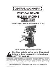
69727 Assembly Diagram<br />
76<br />
76<br />
77<br />
31 31<br />
31<br />
31<br />
30<br />
26<br />
31<br />
31<br />
24<br />
25<br />
29<br />
28<br />
27<br />
101<br />
106<br />
102 103<br />
28 102<br />
104<br />
105<br />
107<br />
108<br />
87<br />
84<br />
113<br />
86<br />
85<br />
85 94<br />
110<br />
88 88<br />
85<br />
81<br />
93<br />
90<br />
85<br />
92<br />
109<br />
82<br />
83<br />
111<br />
2 3<br />
78 78<br />
79<br />
10<br />
11<br />
80<br />
8<br />
8<br />
75<br />
33 34<br />
37 38 39<br />
47<br />
35<br />
48<br />
33<br />
1<br />
48 47<br />
36<br />
32<br />
40<br />
23<br />
23<br />
14<br />
15<br />
19<br />
22<br />
16<br />
21<br />
112<br />
18<br />
17<br />
112<br />
55<br />
20<br />
10<br />
44 54<br />
98<br />
41<br />
10<br />
9<br />
45<br />
42<br />
13<br />
5<br />
51<br />
18<br />
100<br />
97<br />
5<br />
17<br />
5352 50 43 54<br />
9<br />
46<br />
10<br />
5 12<br />
49<br />
4<br />
6 7<br />
53 52 50<br />
96<br />
5<br />
51<br />
99<br />
71<br />
99<br />
95<br />
64<br />
65<br />
59<br />
60<br />
63<br />
61<br />
70<br />
67<br />
62<br />
73<br />
69<br />
58<br />
62<br />
66<br />
57<br />
66<br />
Note: Some parts are listed and shown<br />
for illustration purposes only, and are not<br />
available individually as replacement parts.<br />
68<br />
72<br />
72<br />
Record Product’s Serial Number Here:<br />
Note: If product has no serial number,<br />
record month and year of purchase instead.<br />
MAINTENANCE OPERATION<br />
SETUP<br />
SAFETY<br />
66<br />
56<br />
66<br />
56<br />
56<br />
ITEM 69727<br />
<strong>69730</strong><br />
For technical questions, please call 1-800-520-0882.<br />
Page 21
SAFETY SETUP<br />
OPERATION MAINTENANCE<br />
<strong>69730</strong> <strong>Parts</strong> <strong>List</strong><br />
Part Description Qty<br />
1 Gasket, Cylinder Head 1<br />
2 Cover Subassembly, Cylinder Head 1<br />
3 Gasket, Cylinder Head Cover 1<br />
4 Tube, Breather 1<br />
5 Bolt 4<br />
6 Stud 1<br />
7 Stud 1<br />
8 Stud 2<br />
9 Pin 2<br />
10 Bolt, Cylinder Head 4<br />
11 Plug, Spark 1<br />
12 Head Subassembly, Cylinder 1<br />
13 Crankcase Subassembly 1<br />
14 Sensor, Engine Oil 1<br />
15 Gear Assy, Governor 1<br />
16 Arm, Governor 1<br />
17 Bolt, Drain Plug 2<br />
18 Washer 2<br />
19 Bearing 1<br />
20 Seal, Oil 1<br />
21 Washer 1<br />
22 Pin 1<br />
23 Bolt 2<br />
24 Cover, Crankcase 1<br />
25 Bearing 1<br />
26 Seal, Oil 1<br />
27 Gasket, Crankcase 1<br />
28 Pin 2<br />
29 Dipstick Subassembly, Oil 1<br />
30 Plug Subassembly, Engine Oil 1<br />
31 Bolt 6<br />
32 Crankshaft Assy. 1<br />
33 Clip, Piston Pin 2<br />
34 Piston 1<br />
35 Pin, Piston 1<br />
36 Rod, Connecting 1<br />
37 Ring, Primary 1<br />
38 Ring, Secondary 1<br />
39 Ring Set, Oil 1<br />
40 Camshaft Assy. 1<br />
41 Valve, Exhaust 1<br />
42 Valve, Intake 1<br />
43 Seat, Valve Spring 1<br />
44 Retainer, Exhaust Valve 1<br />
45 Rotator, Valve 1<br />
46 Guide, Seal 1<br />
47 Tappet, Valve 2<br />
48 Lifter, Valve 2<br />
49 Plate Subassembly, Lifter Stopper 1<br />
50 Bolt, Valve Adjusting 2<br />
51 Rocker, Valve 2<br />
Part Description Qty<br />
52 Nut, Valve Adjusting 2<br />
53 Nut, Valve Lock 2<br />
54 Spring, Valve 2<br />
55 Starter Assy, Recoil 1<br />
56 Bolt 3<br />
57 Shroud 1<br />
58 Shroud, Cylinder Body 1<br />
59 Shield,Lower 1<br />
60 Protector, Oil 1<br />
61 Switch Subassembly, Stop Engine 1<br />
62 Bolt 2<br />
63 Bolt 1<br />
64 Collar 1<br />
65 Bolt 1<br />
66 Bolt 4<br />
67 Carburetor Assy. 1<br />
68 Gasket, Air Cleaner 1<br />
69 Gasket, Carburetor 1<br />
70 Plate, Carburetor Insulator 1<br />
71 Gasket, Carburetor Insulator 1<br />
72 Nut 2<br />
73 Cleaner, Air 1<br />
74 Jacket, Rubber 1<br />
75 Gasket, Exhaust Outlet 1<br />
76 Nut 2<br />
77 Muffler Assy 1<br />
78 Tank, Fuel 1<br />
79 Strainer, Fuel 1<br />
80 Cover, Fuel Tank 1<br />
81 Outlet Subassembly, Fuel Tank Oil 1<br />
82 Clamp 3<br />
83 Tube, Fuel 1<br />
84 Bolt 1<br />
85 Nut 2<br />
86 Nut, Flywheel 1<br />
87 Pulley,Starter 1<br />
88 Impeller 1<br />
89 Flywheel Subassembly 1<br />
90 Bolt 2<br />
91 Coil, Ignition 1<br />
92 Control Assy, Throttle 1<br />
93 Bolt 2<br />
94 Spring, Governor 1<br />
95 Rod, Governor 1<br />
96 Spring, Throttle Valve Returning 1<br />
97 Bolt, Governor Support 1<br />
98 Nut 1<br />
99 Support Subassembly, Governor 1<br />
100 Valve, One Way 1<br />
101 Clamp 1<br />
102 Hose, Fuel Steam Rubber 1<br />
Page 22 For technical questions, please call 1-800-520-0882. ITEM 69727<br />
<strong>69730</strong>
5<br />
5<br />
5<br />
5<br />
2 3<br />
4<br />
10<br />
10<br />
10<br />
10<br />
11<br />
8<br />
12<br />
75<br />
8<br />
71<br />
70<br />
6<br />
69<br />
31<br />
7<br />
1<br />
31<br />
30<br />
39<br />
67<br />
9<br />
31<br />
31<br />
9<br />
26<br />
24<br />
25<br />
35<br />
33<br />
36<br />
51<br />
29<br />
28<br />
53 52<br />
51<br />
27<br />
45<br />
50<br />
48<br />
50<br />
48<br />
44<br />
28<br />
47<br />
43 54<br />
46<br />
68<br />
49<br />
32<br />
40<br />
42<br />
23<br />
23<br />
14<br />
15<br />
92<br />
97<br />
93 94<br />
93<br />
95<br />
17<br />
96<br />
19<br />
98<br />
7<br />
22<br />
99<br />
16<br />
18<br />
72<br />
2<br />
21<br />
84<br />
13<br />
83<br />
82<br />
81<br />
82<br />
74<br />
20<br />
91<br />
90<br />
90<br />
5<br />
102<br />
17<br />
18<br />
89<br />
78<br />
2<br />
62<br />
88<br />
10<br />
79<br />
87<br />
62<br />
80<br />
86<br />
58<br />
59<br />
55<br />
64<br />
65<br />
66<br />
60<br />
63<br />
57<br />
56<br />
66<br />
56<br />
56<br />
66<br />
61<br />
66<br />
76 76 77<br />
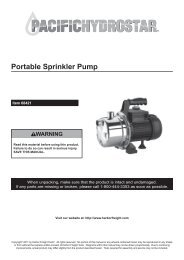
<strong>69730</strong> Assembly Diagram<br />
33 34<br />
5352<br />
7<br />
3<br />
54 41<br />
37 38 47<br />
31 31<br />
8<br />
5 8<br />
1 10<br />
8 0<br />
MAINTENANCE OPERATION<br />
SETUP<br />
SAFETY<br />
ITEM 69727<br />
<strong>69730</strong><br />
For technical questions, please call 1-800-520-0882.<br />
Page 23
Mounting Hole Diagram<br />
6.38 in. / 162mm<br />
2.6 in. / 66mm<br />
3.17 in. / 80.5mm<br />
1.6 in. / 40.5mm<br />
2.97 in. / 75.5mm<br />
Power Take-Off Diagram<br />
2.43 in. / 61.7mm<br />
5/16-24UNF<br />
1.79 in. / 45.5mm<br />
0.1875 in. / 4.78mm<br />
Ø0.75 in. / 19.05mm<br />
0.67 in.<br />
/ 17mm<br />
5/16-24UNF<br />
Ø3.625 in. / 92mm<br />
0.64 in.<br />
/ 16.36mm<br />
4x5/16-24UNF<br />
4.17 in. / 106mm<br />
Note:<br />
Not to scale.<br />
3491 Mission Oaks Blvd. • PO Box 6009 • Camarillo, CA 93011 • (800) 520-0882