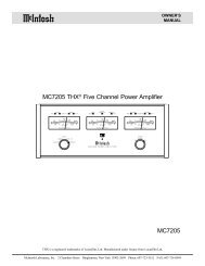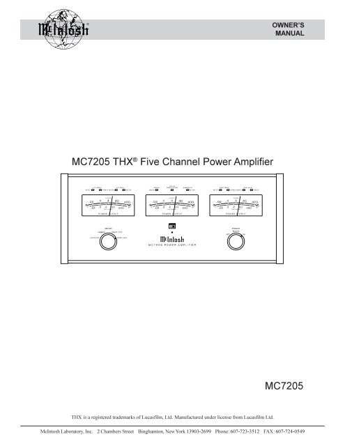
MC7205 MC7205 THX® Five Channel Power Amplifier
MC7205 MC7205 THX® Five Channel Power Amplifier
MC7205 MC7205 THX® Five Channel Power Amplifier

You also want an ePaper? Increase the reach of your titles
YUMPU automatically turns print PDFs into web optimized ePapers that Google loves.
OWNER’S<br />
MANUAL<br />
<strong>MC7205</strong> THX ® <strong>Five</strong> <strong>Channel</strong> <strong>Power</strong> <strong>Amplifier</strong><br />
<strong>MC7205</strong><br />
THX is a registered trademarks of Lucasfilm, Ltd. Manufactured under license from Lucasfilm Ltd.<br />
McIntosh Laboratory, Inc. 2 Chambers Street Binghamton, New York 13903-2699 Phone: 607-723-3512 FAX: 607-724-0549
Thank You, Please Take A Moment,<br />
Customer Service and Table of Contents<br />
Thank You<br />
For your decision to own this McIntosh <strong>MC7205</strong> <strong>Five</strong><br />
<strong>Channel</strong> <strong>Power</strong> <strong>Amplifier</strong> ranks you at the very top among<br />
discriminating music listeners. You now have “The Best.”<br />
The McIntosh dedication to “Quality,” is assurance that you<br />
will receive many years of musical enjoyment from this<br />
unit.<br />
Please take a short time to read the information in this<br />
manual. We want you to be as familiar as possible with all<br />
the features and functions of your new McIntosh <strong>MC7205</strong>.<br />
This will ensure that you receive all the performance benefits<br />
this equipment can offer you, and that it will become a<br />
highly valued part of your home entertainment system.<br />
Please Take A Moment<br />
The serial number, purchase date and McIntosh dealer name<br />
are important to you for possible insurance claim or future<br />
service. The serial number is located on the rear panel of the<br />
equipment. The spaces below have been provided for you to<br />
record that information:<br />
Serial Number:<br />
Purchase Date:<br />
Dealer Name:<br />
Customer Service<br />
If at any time you have questions about your McIntosh<br />
<strong>MC7205</strong> <strong>Five</strong> <strong>Channel</strong> <strong>Power</strong> <strong>Amplifier</strong>, contact your<br />
McIntosh dealer. Your dealer is familiar with your McIntosh<br />
equipment as well as other brands that may be included<br />
in your system and is best qualified to help you.<br />
If it is determined that your <strong>MC7205</strong> is in need of repair,<br />
you can return it to your dealer or you can return it to<br />
McIntosh Laboratory. Contact the McIntosh Repair Department<br />
for assistance at,<br />
McIntosh Laboratory, Inc.<br />
2 Chambers Street<br />
Binghamton, New York 13903<br />
Phone: 607-723-3512<br />
FAX: 607-724-0549<br />
Table of Contents<br />
Thank You.......................................................................... 2<br />
Please Take a Moment ....................................................... 2<br />
Customer Service............................................................... 2<br />
Table of Contents ............................................................... 2<br />
Safety Instructions ............................................................. 3<br />
Introduction ....................................................................... 4<br />
Performance Features ........................................................ 4<br />
Installation ......................................................................... 5<br />
Rear Panel Controls and Connections ............................... 6<br />
How to Connect ................................................................. 7<br />
Front Panel Displays and Controls .................................... 8<br />
How to Operate.................................................................. 9<br />
Specifications .................................................................. 10<br />
Packing Instruction .......................................................... 11<br />
NOTES:<br />
1. Connecting Cables and Connectors are available from the<br />
McIntosh Parts Department:<br />
Data and <strong>Power</strong> Control Cable Part No. 170-202<br />
Six foot, shielded 2 conductor, with 1/8 inch stereo mini<br />
phone plugs on each end.<br />
Control Center to Multi <strong>Channel</strong> <strong>Power</strong> <strong>Amplifier</strong> Cable<br />
Part No. 170-631<br />
Six foot, DB25, shielded, straight through, 25 conductor<br />
male-to-female cable.<br />
2. For additional connection information, refer to the owner’s<br />
manual(s) for any component(s) connected to the <strong>MC7205</strong><br />
<strong>Amplifier</strong>.<br />
3. There is a built-in turn on delay which will mute the speaker<br />
outputs for approximately two seconds when the amplifier is<br />
turned on.<br />
4. It is very important that loudspeaker cables of adequate size<br />
be used in your music system, to ensure that there will be no<br />
power loss or heating. Cable size is specified in Gauge<br />
numbers or AWG, (American Wire Gauge). The smaller the<br />
Gauge number, the larger the wire size:<br />
If your loudspeaker cables are 25 feet (7.62m) or less,<br />
use at least 18 Gauge (AWG) wire size or larger.<br />
If your loudspeaker cables are 50 feet (38.1m) or less,<br />
use at least 16 Gauge (AWG) wire size or larger.<br />
If your loudspeaker cables are 100 feet (76.2m) or less,<br />
use at least 14 Gauge (AWG) wire size or larger.<br />
Copyright 1998 © by McIntosh Laboratory, Inc.<br />
2
Safety Instructions<br />
IMPORTANT SAFETY<br />
INSTRUCTIONS!<br />
PLEASE READ THEM BEFORE<br />
OPERATING THIS EQUIPMENT.<br />
WARNING SHOCK HAZARD -<br />
DO NOT OPEN.<br />
The lightning flash with arrowhead, within an equilateral<br />
triangle, is intended to alert the user to the presence of<br />
uninsulated “dangerous voltage” within the product’s<br />
enclosure that may be of sufficient magnitude to constitute<br />
a risk of electric shock to persons.<br />
AVIS RISQUE DE CHOC -<br />
NE PAS OUVRIR.<br />
The exclamation point within an equilateral triangle is<br />
intended to alert the user to the presence of important<br />
operating and maintenance (servicing) instructions in<br />
the literature accompanying the appliance.<br />
NO USER-SERVICEABLE<br />
PARTS INSIDE. REFER<br />
SERVICING TO<br />
QUALIFIED PERSONNEL<br />
To prevent the risk of electric shock, do not remove<br />
cover (or back). No user serviceable parts inside. Refer<br />
servicing to qualified personnel.<br />
General:<br />
1. Read all the safety and operating instructions, contained<br />
in this owner’s manual, before operating this<br />
equipment.<br />
2. Retain this owner’s manual for future reference about<br />
safety and operating instructions.<br />
3. Adhere to all warnings and operating instructions.<br />
4. Follow all operating and use instructions.<br />
5. Warning: To reduce risk of fire or electrical shock,<br />
do not expose this equipment to rain or moisture.<br />
This unit is capable of producing high sound pressure<br />
levels. Continued exposure to high sound pressure<br />
levels can cause permanent hearing impairment<br />
or loss. User caution is advised and ear protection<br />
is recommended when playing at high volumes.<br />
6. Caution: to prevent electrical shock do not use this<br />
(polarized) plug with an extension cord, receptacle<br />
or other outlet unless the blades can be fully inserted<br />
to prevent blade exposure.<br />
Attention: pour pevenir les chocs elecriques pas<br />
utiliser cette fiche polarisee avec un prolongateur,<br />
une prise de courant ou un autre sortie de courant,<br />
sauf si les lames peuvent etre inserees afond ans en<br />
laisser aucune partie a decouvert.<br />
7. For added protection for this product during a lightning<br />
storm, or when it is left unattended and unused for long<br />
periods of time, unplug it from the wall outlet and disconnect<br />
the antenna or cable system. This will prevent<br />
damage to the product due to lightning or power line<br />
surges.<br />
8. Do not use attachments not recommended in this<br />
owner’s manual as they may cause hazards.<br />
Installation:<br />
9. Locate the equipment for proper ventilation. For example,<br />
the equipment should not be placed on a bed,<br />
sofa, rug, or similar surface that may block ventilation<br />
openings; or, placed in a built-in installation, such as a<br />
bookcase or cabinet, that may impede the flow of air<br />
through the ventilation openings.<br />
10. Locate the equipment away from heat sources such as<br />
radiators, heat registers, stoves, or other appliance (including<br />
amplifiers) that produce heat.<br />
11. Mount the equipment in a wall or cabinet only as described<br />
in this owner’s manual<br />
12. Do not use this equipment near water; for example,<br />
near a bathtub, washbowl, kitchen sink, laundry tub, in<br />
a wet basement or near a swimming pool, etc.<br />
13. Do not place this product on an unstable cart, stand,<br />
tripod, bracket, or table. The equipment may fall, causing<br />
serious injury to a person, and serious damage to<br />
the product.<br />
Connection:<br />
14. Connect this equipment only to the type of AC power<br />
source as marked on the unit.<br />
15. Route AC power cords so that they are not likely to be<br />
walked on or pinched by items placed upon or against<br />
them, paying particular attention to cords at plugs, convenience<br />
receptacles, and the point where they exit from<br />
the instrument.<br />
16. Do not defeat the inherent design features of the polarized<br />
plug. Non-polarized line cord adapters will defeat<br />
the safety provided by the polarized AC plug. If the<br />
plug should fail to fit, contact your electrician to replace<br />
your obsolete outlet. Do not defeat the safety purpose<br />
of the grounding-type plug.<br />
3
Safety Instructions con’t,<br />
Introduction and Performance Features<br />
17. Do not overload wall outlets, extension cords or integral<br />
convenience receptacles as this can result in a risk<br />
of fire or electric shock.<br />
Care of Equipment:<br />
18. Clean the instrument by dusting with a dry cloth. Unplug<br />
this equipment from the wall outlet and clean the<br />
panel with a cloth moistened with a window cleaner.<br />
Do not use liquid cleaners or aerosol cleaners.<br />
19. Do not permit objects of any kind to be pushed and/or<br />
fall into the equipment through enclosure openings.<br />
Never spill liquids into the equipment through enclosure<br />
openings.<br />
20. Unplug the power cord from the AC power outlet<br />
when left unused for a long period of time.<br />
Repair of Equipment:<br />
21. Unplug this equipment from the wall outlet and refer<br />
servicing to a qualified service personnel under the following<br />
conditions:<br />
A. The AC power cord or the plug has been damaged.<br />
B. Objects have fallen, or liquid has been spilled into<br />
the equipment.<br />
C. The equipment has been exposed to rain or water.<br />
D. The equipment does not operate normally by following<br />
the operating instructions contained within<br />
this owner’s manual. Adjust only those controls<br />
that are covered by the operating instructions, as an<br />
improper adjustment of other controls may result<br />
in damage and will often require extensive work by<br />
a qualified technician to restore the product to its<br />
normal operation.<br />
E. The equipment has been dropped or damaged in any<br />
way.<br />
F. The equipment exhibits a distinct change in performance<br />
- this indicates a need for service.<br />
22. Do not attempt to service beyond that described in the<br />
operating instructions. All other service should be referred<br />
to qualified service personnel.<br />
23. When replacement parts are required, be sure the service<br />
technician has used replacement parts specified by<br />
McIntosh or have the same characteristics as the original<br />
part. Unauthorized substitutions may result in fire,<br />
electric shock, or other hazards.<br />
24. Upon completion of any service or repairs to this product,<br />
ask the service technician to perform safety checks<br />
to determine that the product is in proper operating condition.<br />
Introduction<br />
Now you can take advantage of traditional McIntosh standards<br />
of excellence in the <strong>MC7205</strong>, power amplifier. <strong>Five</strong><br />
200 watt, high current output channels will deliver outstanding<br />
audio performance for your McIntosh Home Theater<br />
System. The <strong>MC7205</strong> is THX certified and easily<br />
meets the demanding Lucasfilm, Ltd., standards for accuracy<br />
in home theater electronics.<br />
Performance Features<br />
· <strong>Power</strong> Output<br />
The <strong>MC7205</strong> consists of five separate power amplifier<br />
channels, each capable of 200 watts into 4 ohm speakers<br />
with less than 0.005% distortion. This is 1000 watts of<br />
McIntosh power in a single package.<br />
· <strong>Power</strong> Guard<br />
All five channels include the patented McIntosh <strong>Power</strong><br />
Guard circuit that prevents the amplifier from being<br />
overdriven into clipping with its harsh distorted sound that<br />
can also damage your valuable loudspeakers.<br />
· Sentry Monitor and Thermal Protection<br />
McIntosh Sentry Monitor power output stage protection<br />
circuits are present on all five channels to ensure the<br />
<strong>MC7205</strong> will have a long and trouble free operating life.<br />
Built-in thermal protection circuits guard against overheating<br />
which could shorten the normal long life expectancy of<br />
your McIntosh power amplifier.<br />
· Direct Current Protection<br />
Direct Current sensing circuits on each channel provide<br />
extra protection for your valuable loudspeakers.<br />
· Illuminated <strong>Power</strong> Meters<br />
Three front panel, illuminated output wattmeters can be<br />
selected to precisely indicate the power output of each of<br />
the five channels as well as the relative power output produced<br />
by a THX certified powered subwoofer amplifier.<br />
· Convenient Single Cable Hookup<br />
A rear panel connector provides for the convenience of using<br />
a single cable, (DB25 computer style) to receive all audio<br />
and power control signals from a McIntosh THX Control<br />
Center.<br />
4
Installation<br />
Installation<br />
The <strong>MC7205</strong> can be placed upright on a table or shelf,<br />
standing on its four feet. It also can be custom installed in a<br />
piece of furniture or cabinet of your choice. The required<br />
panel cutout, ventilation cutout and unit dimensions are<br />
shown.<br />
Always provide adequate ventilation for your <strong>MC7205</strong>.<br />
Cool operation ensures the longest possible operating life<br />
for any electronic instrument. Do not install the <strong>MC7205</strong><br />
directly above a heat generating component such as a high<br />
powered amplifier. If all the components are installed in a<br />
single cabinet, a quiet running ventilation fan can be a definite<br />
asset in maintaining all the system components at the<br />
coolest possible operating temperature.<br />
A custom cabinet installation should provide the following<br />
minimum spacing dimensions for cool operation. Allow<br />
at least 2 inches (5.1 cm) above the top and 1 inch (2.54<br />
cm) on each side of the amplifier, so that airflow is not obstructed.<br />
Allow 21 inches (53.3 cm) depth behind the<br />
mounting panel, which includes clearance for connectors.<br />
Allow 1-1/8 inches (2.9 cm) in front of the mounting panel<br />
for knob clearance. Be sure to cut out a ventilation hole in<br />
the mounting shelf according to the dimensions in the<br />
drawing.<br />
17-1/2"<br />
444mm<br />
1/4"<br />
6mm<br />
17-1/16"<br />
433.4mm<br />
Outline of Front Panel<br />
Edge of Cutout<br />
Front View of a <strong>MC7205</strong><br />
custom installed<br />
End Caps<br />
7-1/16"<br />
179.8mm<br />
6-9/16"<br />
166.7mm<br />
Panel Height<br />
7.00"<br />
177.8mm<br />
(Front View)<br />
7/32"<br />
5.3mm<br />
Side View of a <strong>MC7205</strong><br />
custom installed<br />
3/16"<br />
5.1mm<br />
Bottom of Cutout and Top<br />
of Support Shelf Must<br />
Coincide<br />
Mounting Surface<br />
Outline of Unit<br />
(Side View)<br />
Support Shelf<br />
Mounting Bracket at Both Sides of the Rear Panel.<br />
Fasten with 6-32 x 3/8 Machine Screw and Washer to Chassis.<br />
Fasten with 6 x 1/2 Wood Screw and Washer to Support Shelf<br />
Support Shelf<br />
Cut Out Center<br />
for Ventilation<br />
Mounting Surface<br />
Bottom View of a <strong>MC7205</strong><br />
custom installed<br />
6"<br />
15"<br />
Cut Out Center<br />
for Ventilation<br />
(Bottom View)<br />
9"<br />
5
<strong>MC7205</strong> Rear Panel Controls and<br />
Connections<br />
<strong>MC7205</strong> Rear Panel Controls and<br />
Connections<br />
INPUTS for discrete audio cables<br />
from a preamplifier or control<br />
center audio outputs<br />
INPUT for discrete audio cable<br />
from a preamplifier or control<br />
center audio output<br />
INPUTS for discrete audio cables<br />
from a preamplifier or control<br />
center audio outputs<br />
Connect the <strong>MC7205</strong><br />
power cord to a live<br />
AC outlet. Refer to information<br />
on the back<br />
panel to determine the<br />
correct voltage.<br />
SUB IN/OUT accepts a<br />
subwoofer input signal to<br />
activate the subwoofer<br />
power meter circuit. If a 25<br />
conductor cable is being<br />
used with a McIntosh Control<br />
Center this jack will<br />
provide a signal out to a<br />
subwoofer amplifier.<br />
THX INPUT Connector<br />
accepts a 25 conductor<br />
cable that connects all<br />
audio and power control<br />
signals from a McIntosh<br />
Control Center<br />
Individual Input<br />
LEVEL controls<br />
for the Left channels<br />
Individual Input<br />
LEVEL controls for<br />
Right channels and<br />
Center channel<br />
SUB METER CAL<br />
control for meter<br />
calibration of the<br />
Subwoofer <strong>Channel</strong><br />
Main Fuse holder,<br />
refer to infromation<br />
on the back panel<br />
of your <strong>MC7205</strong> to<br />
determine the correct<br />
fuse size and<br />
rating.<br />
OUPUT Connections for<br />
8 or 4 ohm loudspeakers<br />
OUTPUT Connections for 8<br />
or 4 ohm loudspeakers<br />
OUTPUT Connections for<br />
8 or 4 ohm loudspeakers<br />
POWER CONTROL In receives<br />
turn on/off signals from a McIntosh<br />
component and the POWER CON-<br />
TROL Out sends that turn on/off<br />
signal to the next McIntosh component.<br />
6
123456789<br />
123456789<br />
123456789<br />
123456789<br />
123456789<br />
123456789<br />
123456789<br />
123456789<br />
123456789<br />
123456789<br />
123456789<br />
123456789<br />
123456789<br />
123456789<br />
123456789<br />
123456789<br />
123456789<br />
123456789<br />
123456789<br />
123456789<br />
123456789<br />
123456789<br />
123456789<br />
123456789<br />
123456789<br />
123456789<br />
123456789<br />
123456789<br />
123456789<br />
123456789<br />
123456789<br />
123456789<br />
123456789<br />
123456789<br />
123456789<br />
123456789<br />
123456789<br />
123456789<br />
123456789<br />
123456789<br />
123456789<br />
123456789<br />
123456789<br />
123456789<br />
123456789<br />
123456789<br />
123456789<br />
123456789<br />
123456789<br />
123456789<br />
123456789<br />
123456789<br />
123456789<br />
123456789<br />
123456789<br />
123456789<br />
123456789<br />
123456789<br />
123456789<br />
123456789<br />
How to Connect the <strong>MC7205</strong><br />
with a C39/MX130<br />
How to Connect the <strong>MC7205</strong><br />
with a C39/MX130<br />
1. Connect the <strong>MC7205</strong> power cord to a live AC outlet.<br />
2. Connect the loudspeaker cables to the appropriate channel<br />
output connectors, being careful to observe the correct<br />
polarities.<br />
Note: To prevent the possibility of<br />
user contact with<br />
potentially dangerous<br />
voltages, install the<br />
protective cover(s) over the<br />
loudspeaker output<br />
terminals after the<br />
loudspeaker cables have<br />
been connected. The covers<br />
and cover mounting screws<br />
are located in an accessory<br />
package that is enclosed in the amplifier shipping<br />
McIntosh MX130 Control Center<br />
carton. There are two types of screws in the package.<br />
Install the protective covers with the Phillips, 6-32 by<br />
5/16 inch self tapping screws. The other screws are<br />
No. 6 by ½ inch wood screws used to secure the<br />
amplifier custom mounting brackets to a shelf.<br />
3. Connect a single DB25 computer type cable from the<br />
THX output of a control center to the <strong>MC7205</strong> THX<br />
Input connector for all six audio channels and power<br />
control.<br />
4. Connect the <strong>MC7205</strong> Sub In/Out to the McIntosh SL-1<br />
subwoofer amplifier THX input and a power control<br />
cable from the <strong>MC7205</strong> <strong>Power</strong> Control Out to the SL-1<br />
<strong>Power</strong> Control In.<br />
Note: An optional hookup is to use discrete cables from a<br />
McIntosh Control Center to inputs of the <strong>MC7205</strong>.<br />
Connect a “Y” adapter to the Control Center<br />
Subwoofer Output, with one cable to the SL-1<br />
subwoofer THX input and a second cable to the<br />
<strong>MC7205</strong> Sub In/Out jack. Connect a power control<br />
cable from the Control Center <strong>Power</strong> Control Out to the<br />
<strong>MC7205</strong> power control in jack and connect a power<br />
control cable from the <strong>MC7205</strong> <strong>Power</strong> Control Out to<br />
the SL-1 <strong>Power</strong> Control In.<br />
McIntosh SL-1<br />
<strong>Power</strong> Sub-Woofer<br />
To AC Outlet<br />
Front Right<br />
Speaker<br />
Front Center<br />
Speaker<br />
Front Left<br />
Speaker<br />
Surround Right<br />
Speaker<br />
Surround Left<br />
Speaker<br />
7
<strong>MC7205</strong> Front Panel Displays<br />
and Controls<br />
<strong>MC7205</strong> Front Panel Displays and Controls<br />
POWER GUARD LED’s<br />
light when the amplifier<br />
channel POWER GUARD<br />
circuit activates<br />
POWER GUARD<br />
LED’s light when the<br />
amplifier channel<br />
POWER GUARD<br />
circuit activates<br />
POWER GUARD LED’s<br />
light when the amplifier<br />
channel POWER GUARD<br />
circuit activates<br />
METER LED’s<br />
Indicate which<br />
channel(s) the<br />
power meter is<br />
reading<br />
METER LED’s<br />
Indicate which<br />
channel(s) the<br />
power meter is<br />
reading<br />
METER LED’s<br />
Indicate which<br />
channel(s) the<br />
power meter is<br />
reading<br />
METER LED’s<br />
Indicate which<br />
channel(s) the<br />
power meter is<br />
reading<br />
Remote On<br />
Indicator<br />
METER Switch selects<br />
the display modes of the<br />
power output meters<br />
POWER Switch Turns<br />
AC power on/off, or on/<br />
remote<br />
METERS indicate power output<br />
of the amplifier channels<br />
according to the Meter switch<br />
setting<br />
8
How to Operate the<br />
<strong>MC7205</strong><br />
How to Operate the <strong>MC7205</strong><br />
Input Level Controls<br />
When using a McIntosh Control Center set all five level<br />
controls to the 2V position. If a<br />
preamplifier or control center<br />
has a 1V output rating and/or a<br />
built-in THX module, set the<br />
controls to the 1V position. If<br />
an increase or decrease in amplifier<br />
sensitivity is required for<br />
other applications, set the<br />
Figure 2<br />
controls as desired. Refer to<br />
Figure 2.<br />
Subwoofer Meter Calibration<br />
When using a McIntosh SL-1 powered subwoofer, set the<br />
Sub Meter Cal control to the 1V THX position for the correct<br />
subwoofer amplifier power output indication. Refer to<br />
Figure 1.<br />
<strong>Power</strong> On<br />
To have the <strong>MC7205</strong> turn on or off when a control center<br />
turns on or off, rotate the power switch to the remote position.<br />
For manual operation, rotate the power switch to the<br />
on or off position as desired.<br />
Note: There must be a power control connection between the<br />
<strong>MC7205</strong> and the McIntosh Control Center in order for<br />
the remote power turn on to function.<br />
Meter Selection<br />
Rotate the meter mode switch to select the meter operation<br />
mode you desire:<br />
Lights Off - Meter lights are turned off and the meters<br />
are in the summed mode.<br />
Summed - Each meter displays the combined outputs of<br />
two channels. The left meter indicates the left<br />
front combined with the left surround, the center<br />
meter indicates the center combined with<br />
the subwoofer and the right meter indicates<br />
the right front combined with the right surround.<br />
In this meter mode refer to the upper<br />
meter scale(s).<br />
Front/Ctr - The left meter indicates the left front channel,<br />
the center meter indicates the center channel<br />
and the right meter indicates the right front<br />
channel. In this meter mode refer to the lower<br />
meter scale(s).<br />
Surr/Sub - The left meter indicates the left surround channel,<br />
the center meter indicates the relative<br />
power of the subwoofer amplifier and the right<br />
meter indicates the right surround channel. In<br />
this meter mode refer to the lower meter<br />
scale(s).<br />
How to Read the <strong>Power</strong> Output Meters<br />
The <strong>MC7205</strong> <strong>Power</strong> Output Meter scales are based on using<br />
4 ohm loudspeakers. If 8 ohm speakers are used, the<br />
actual power output is one half the power available to drive<br />
4 ohm loudspeakers. Use the chart(s) below to determine<br />
the actual power output sent to your loudspeakers. Refer to<br />
figure 3.<br />
Summed <strong>Channel</strong>s Meter Readings<br />
Meter Reading With 4Ω Loudspeaker(s) With 8Ω Loudspeaker(s)<br />
.04 .04 Watts .02 Watts<br />
.4 .4 Watts .2 Watts<br />
4 4 Watts 2 Watts<br />
40 40 Watts 20 Watts<br />
400 400 Watts 200 Watts<br />
Single <strong>Channel</strong> Meter Readings<br />
Meter Reading With 4Ω Loudspeaker(s) With 8Ω Loudspeaker(s)<br />
.02 .02 Watts .01 Watts<br />
.2 .2 Watts .01 Watts<br />
2 2 Watts 1 Watts<br />
20 20 Watts 10 Watts<br />
Figure 3<br />
200 200 Watts 100 Watts<br />
9
Specifications<br />
Specifications<br />
<strong>Power</strong> Output Per <strong>Channel</strong><br />
200 watts into 4 ohm loads or 120 watts into 8 ohm loads<br />
minimum sine wave continuous average power output per<br />
channel, all channels operating.<br />
Output Load Impedance<br />
8 or 4 ohms<br />
Rated <strong>Power</strong> Band<br />
20Hz to 20,000Hz<br />
Dynamic Headroom<br />
1.6dB<br />
Frequency Response<br />
+0, -0.25dB from 20Hz to 20,000Hz<br />
+0, -3dB from 10Hz to 100,000Hz<br />
Total Harmonic Distortion<br />
0.005% maximum at any power level from 250 milliwatts<br />
to rated power per channel from 20Hz to 20,000Hz, all<br />
channels operating.<br />
<strong>Power</strong> Requirements<br />
100 Volts, 50/60Hz at 1080 watts<br />
110 Volts, 50/60Hz at 1080 watts<br />
120 Volts, 50/60Hz at 1080 watts<br />
220 Volts, 50/60Hz at 1080 watts<br />
230 Volts, 50/60Hz at 1080 watts<br />
240 Volts, 50/60Hz at 1080 watts<br />
NOTE: Refer to the rear panel of the <strong>MC7205</strong> for the correct<br />
voltage<br />
Dimensions<br />
Front Panel: 17/1/2 inches (44.5cm) wide, 7-1/16 inches<br />
(17.9cm) high. Depth behind front mounting panel is 21<br />
inches (53.3cm) including clearance for connectors. Panel<br />
clearance required in front of mounting panel is 1-1/8<br />
inches (2.9cm).<br />
Weight<br />
53 pounds (24Kg) net, 72 pounds (32.7Kg) in shipping carton<br />
Intermodulation Distortion<br />
0.005% maximum if instantaneous peak output per channel<br />
does not exceed twice the rated output with all channels<br />
operating for any combination of frequencies from 20Hz to<br />
20,000Hz.<br />
Signal To Noise Ratio<br />
113dB below rated output, (A Weighted)<br />
Sensitivity<br />
1 volt (2.0V at level control center detent position)<br />
Input Impedance<br />
10,000 ohms<br />
Damping Factor (Wide Band)<br />
200 @ 8 ohms<br />
100 @ 4 ohms<br />
<strong>Power</strong> Supply Energy Storage<br />
215 Joules<br />
10
Packing Instructions<br />
Packing Instructions<br />
In the event it is necessary to repack the equipment for<br />
shipment, the equipment must be packed exactly as shown<br />
below. It is very important that the four plastic feet are attached<br />
to the bottom of the equipment. Three #10 x 2-1/4”<br />
screws and washers must be used to fasten the unit securely<br />
to the bottom pad and wood skid This will ensure the<br />
proper equipment location on the bottom pad. Failure to do<br />
this will result in shipping damage.<br />
Use the original shipping carton and interior parts only if<br />
they are all in good serviceable condition. If a shipping carton<br />
or any of the interior part(s) are needed, please call or<br />
write Customer Service Department of McIntosh Laboratory.<br />
Please see the Part List for the correct part numbers.<br />
Quantity Part Number Description<br />
1 033888 Shipping carton only<br />
4 033887 End cap (Foam pad)<br />
1 033697 Inside carton only<br />
1 033725 Top Pad<br />
1 034008 Bottom pad<br />
3 017218 Plastic foot (spacer)<br />
1 033699 Wood skid<br />
3 101169 #10 x 2-¼” Wood screw<br />
3 104033 #10 x 1-¾” Wood screw<br />
4 017218 Plastic foot<br />
4 100159 #10-32 x ¾” Machine screw<br />
4 104083 #10 x 7/16” Flat washer<br />
1 040542 Shipping carton complete with<br />
all the above parts<br />
11
McIntosh Laboratory, Inc.<br />
2 Chambers Street<br />
Binghamton, NY 13903<br />
McIntosh Part No. 040539